Embed Size (px)
Citation preview

MODEL-DRIVEN SOFTWARE DEVELOPMENT USING A METAMODEL-BASED EXTENSION MECHANISM FOR
UML
Inauguraldissertation zur Erlangung eines Doktors der Wirtschaftswissenschaften
der Universität Mannheim
vorgelegt von
Diplom-Wirtschaftsinformatiker Ralf Gitzel
aus München
im März 2005

Dekan:
Referent:
Koreferent:
Tag der mündlichen Prüfung:

Page i
Table of Contents Model-Driven Software Development Using a Metamodel-Based Extension Mechanism for UML ............................................................................................. 11 Introduction .................................................................................................... 1
1.1 Motivation ............................................................................................... 11.2 Objectives ................................................................................................ 31.3 Chapter Overview .................................................................................... 31.4 Scientific Contributions ........................................................................... 4
2 Metamodeling Hierarchies ............................................................................. 52.1 Conventional Applications of Metamodeling ......................................... 52.2 Metamodeling Related Standards ............................................................ 7
2.2.1 Unified Modeling Language ............................................................. 72.2.2 Meta Object Facility ......................................................................... 72.2.3 Java Metadata Interface .................................................................... 82.2.4 XML Metadata Interchange .............................................................. 9
2.3 Core Concepts of Object-Oriented Metamodeling .................................. 92.3.1 Definitions ...................................................................................... 102.3.1.1 Basic Definitions ......................................................................... 102.3.1.2 Metamodeling Definitions .......................................................... 112.3.1.3 Comparison With Alternative Definitions .................................. 122.3.2 Model Semantics ............................................................................ 132.3.2.1 Syntax versus Semantics ............................................................. 142.3.2.2 A Pragmatic Approach to Semantics .......................................... 152.3.3 Principles and Examples ................................................................. 162.3.3.1 Core Elements of MOF ............................................................... 162.3.3.2 The Model/Metamodel Dualism ................................................. 172.3.3.3 Class Instantiation Semantics ...................................................... 192.3.3.4 Association Instantiation Semantics ........................................... 19
2.4 A Design Space for Metamodel Hierarchies ......................................... 212.4.1 Linear Versus Nonlinear Metamodel Hierarchies .......................... 232.4.2 Number of Layers ........................................................................... 302.4.3 General Instantiation Semantics ..................................................... 31
Page ii
2.4.4 Strictness Definition ....................................................................... 322.4.5 Shallow Versus Deep Instantiation ................................................ 362.4.6 Explicit or Implicit Real World Level ............................................ 392.4.7 Linguistic Model Element Definitions ........................................... 402.4.8 Axiomatic Versus Recursive Top Level......................................... 432.4.9 Evaluation of a Metamodel Hierarchy ........................................... 46
2.5 Conclusion ............................................................................................. 483 Model-Driven Development ......................................................................... 49
3.1 Goals and Aspired Benefits of MDD .................................................... 493.1.1 Resistance to Change ...................................................................... 503.1.2 Increased Level of Abstraction ....................................................... 51
3.2 MDD Origins and State of the Art ........................................................ 533.2.1 Origins of MDD .............................................................................. 543.2.2 MDD State of the Art ..................................................................... 553.2.2.1 The Model-Driven Architecture .................................................. 553.2.2.2 ArcStyler ..................................................................................... 573.2.2.3 Executable UML ......................................................................... 57
3.3 A Critical Evaluation of MDD Approaches .......................................... 583.3.1 Open Questions ............................................................................... 593.3.2 Problems in the Context of MDD and Potential Solutions ............ 603.3.2.1 Platform Independence ................................................................ 603.3.2.2 Code Generation .......................................................................... 623.3.2.3 Other Aspects .............................................................................. 64
3.4 A New Vision of MDD ......................................................................... 663.5 Domain-Specific MDD ......................................................................... 67
3.5.1 Requirements for Domain-Specific MDD...................................... 693.5.2 Non-Metamodeling Approaches to Domain-Specific MDD.......... 703.5.2.1 Class Libraries and Inheritance ................................................... 713.5.3 Single Metalayer Approaches ......................................................... 733.5.3.1 Patterns ........................................................................................ 743.5.3.2 Stereotypes .................................................................................. 743.5.4 Metamodeling Hierarchy Approaches ............................................ 77
Page iii
3.5.4.1 Classical Metamodel Hierarchies ................................................ 783.5.4.2 Nonlinear Hierarchies ................................................................. 79
3.6 Conclusions ........................................................................................... 824 An Analysis of the Web Application Domain ............................................. 84
4.1 Properties and Problems of Web Applications ..................................... 844.1.1 Technical Properties and Problems ................................................ 844.1.2 Usability Issues and Properties ....................................................... 864.1.2.1 Consistency ................................................................................. 874.1.2.2 Navigability and Site Structure ................................................... 874.1.2.3 Visual Presentation ...................................................................... 894.1.2.4 Internationalization ..................................................................... 904.1.2.5 Accessibility ................................................................................ 914.1.2.6 User- and Domain-Related Issues ............................................... 924.1.3 Additional Problems ....................................................................... 924.1.4 Summary ......................................................................................... 93
4.2 Conventional Approaches to Web Engineering .................................... 934.2.1 Web Design Languages .................................................................. 944.2.1.1 The Object-Oriented Hypermedia Design Method ..................... 964.2.1.2 The Web Modeling Language ..................................................... 984.2.1.3 Other Web Design Languages .................................................... 984.2.2 Web Application Frameworks ........................................................ 99
4.3 MDD Approaches to Web Engineering .............................................. 1034.3.1 Frameworks, Web Design Languages and MDD ......................... 1034.3.2 The Contribution of MDD to Web Engineering .......................... 1034.3.3 Existing Approaches ..................................................................... 105
4.4 Conclusions ......................................................................................... 1085 The OMEGA Approach ............................................................................. 109
5.1 A Metamodel-Based Extension Mechanism for UML ....................... 1095.1.1 The Metamodel for OMEGA Hierarchies .................................... 1115.1.1.1 MetaElements and Instances ..................................................... 1135.1.1.2 Model Layers ............................................................................. 1145.1.1.3 MetaClasses and MetaAttributes .............................................. 116
Page iv
5.1.1.4 MetaAssociations ...................................................................... 1195.1.1.5 Implementation Notes ............................................................... 1215.1.1.6 Properties of the OMEGA Metamodel ..................................... 1215.1.2 The Metamodel for OMEGA/Dynamic Hierarchies .................... 1245.1.2.1 Instance and MetaElement ........................................................ 1265.1.2.2 States and Transitions ............................................................... 1265.1.2.3 MetaStates and States ................................................................ 1285.1.2.4 MetaStateCharts and StateCharts .............................................. 1285.1.2.5 Properties of the OMEGA/Dynamic Metamodel ..................... 1295.1.3 Mapping to UML Profiles ............................................................ 1305.1.4 Using the Extension Mechanism for Code Generation ................ 131
5.2 A Metamodel Hierarchy for MDD ...................................................... 1325.2.1 The Static Metamodels ................................................................. 1335.2.1.1 The M3 Layer: Web Application Structure .............................. 1335.2.1.2 The M2 Layer: Content Management System Structure .......... 1355.2.2 The Dynamic Metamodels ............................................................ 1375.2.2.1 The M3 Layer: Web Application Behavior .............................. 1375.2.2.2 The M2 Layer: Content Management System Behavior .......... 140
5.3 Prototypical Implementations .............................................................. 1415.3.1 General Plugin Architecture ......................................................... 1425.3.2 The OMEGA Modeling Tool ....................................................... 1435.3.3 The OMEGA Data Structure Plugin ............................................. 1445.3.3.1 The Mapping From OMEGA to S-OMEGA ............................ 1465.3.3.2 The Mapping From OMEGA/Dynamic to S-OMEGA ............ 1475.3.4 The Code Generation Module ...................................................... 1475.3.4.1 Code Generation Process .......................................................... 1475.3.4.2 Static Code Generation Templates ............................................ 1495.3.4.3 Dynamic Generation Templates ................................................ 1495.3.4.4 Code Generation for the Web Domain ..................................... 1515.3.5 A Brief Introduction to the COBANA Framework ...................... 1515.3.5.1 Basic Concept ............................................................................ 1525.3.5.2 Framework Architecture ........................................................... 152
Page v
5.3.5.3 Navigation ................................................................................. 1535.3.5.4 Addressed Problems .................................................................. 154
5.4 The Digital Library Example ............................................................... 1545.4.1 Submission Mechanism Variant 1 ................................................ 1555.4.1.1 Static Model .............................................................................. 1555.4.1.2 Dynamic Model ......................................................................... 1565.4.2 Submission Mechanism Variant 2 ................................................ 1575.4.2.1 Static Model .............................................................................. 1585.4.2.2 Dynamic Model ......................................................................... 158
5.5 Summary .............................................................................................. 1606 Conclusions and Future Work .................................................................... 161
6.1 Theoretical and Practical Evaluation ................................................... 1616.1.1 Evaluation Approach .................................................................... 1616.1.2 Scalability and General Applicability of the Example ................. 1626.1.3 Quality Criteria for the Extension Mechanism ............................. 1636.1.3.1 Assessing the Variable Costs .................................................... 1646.1.3.2 Assessing the Fixed Costs Due to Time Overhead ................... 1646.1.3.3 Assessing the Fixed Costs due to Initial Training .................... 1676.1.4 Explanations and Conclusions ...................................................... 168
6.2 General Assessment of the OMEGA Approach .................................. 1696.2.1 Complexity of the Approach ........................................................ 1696.2.2 The General Layout of the Model Hierarchy ............................... 1696.2.3 Conceptual Issues ......................................................................... 170
6.3 Open Questions and Future Work ....................................................... 1716.4 Related Work ....................................................................................... 172
6.4.1 UML as a Family of Languages ................................................... 1726.4.2 Software Product Lines ................................................................ 1736.4.3 MetaCASE Tools .......................................................................... 1736.4.4 Software Factories ........................................................................ 174
6.5 Conclusion ........................................................................................... 174
Page vi
Table of Figures Figure 1 - Hypothetical Cost Comparison ............................................................ 2Figure 2 - Semantics and Syntax of Modeling Languages ................................. 14Figure 3 - Example MOF Elements .................................................................... 16Figure 4 - Core Elements of MOF ...................................................................... 17Figure 5 - The Model/Metamodel Dualism ........................................................ 18Figure 6 - Instantiation Semantics of Association .............................................. 20Figure 7 - Naïve Linear Hierarchy ...................................................................... 24Figure 8 - MOF's Layer Limitation due to its Instantiation Semantics .............. 25Figure 9 - Orthogonal Metamodel Hierarchy...................................................... 26Figure 10 - Violations of Strictness .................................................................... 33Figure 11 - A Scenario With Relaxed Strictness ................................................ 34Figure 12 - Introducing a Persistence Metaclass in M2 ...................................... 35Figure 13 - Potency of Attributes ........................................................................ 37Figure 14 - An Example of Recursive Metamodeling ........................................ 44Figure 15 - Inheritance as a Substitute for Instantiation ..................................... 72Figure 16 - Stereotypes ....................................................................................... 75Figure 17 - The Classical Metamodel Hierarchy (see [160], pg. 2-3) ................ 78Figure 18 - A Metamodel for the Domain of Art ................................................ 80Figure 19 - Improved Artist Metamodel ............................................................. 80Figure 20 - Modularity in Hierarchies ................................................................ 81Figure 21 - Different Levels of Abstraction in Hierarchies ................................ 82Figure 22 - An Overview of Different Web Application Issues ......................... 94Figure 23 - Navigational Structures Versus Explicit Links ................................ 95Figure 24 - Pages With Multiple Contexts .......................................................... 96Figure 25 - The Elements of the Extension Mechanism ................................... 110Figure 26 - OMEGA Metamodel Overview ..................................................... 112Figure 27 - OMEGA Instantiation Concept ...................................................... 113Figure 28 - OMEGA Model Layer Concept ..................................................... 115Figure 29 - Examples of Frozen Layers ............................................................ 116Figure 30 - OMEGA MetaClass-Class Instantiation Concept .......................... 116Figure 31 - MetaAttributes ................................................................................ 118
Page vii
Figure 32 - Motivation for the Inclusion of Slots ............................................. 119Figure 33 - MetaAssociation-Association Instantiation Concept ..................... 120Figure 34 - MetaAssociation and Association .................................................. 120Figure 35 - OMEGA Implementation and Usage ............................................. 121Figure 36 - OMEGA/Dynamic and OMEGA ................................................... 125Figure 37 - The OMEGA/Dynamic Linguistic Metamodel .............................. 126Figure 38 - OMEGA/Dynamic Instance-Level Elements ................................. 127Figure 39 - An Example for the Interpretation of Substates ............................. 127Figure 40 - OMEGA/Dynamic State Concept .................................................. 128Figure 41 - OMEGA/Dynamic StateChart Concept ......................................... 129Figure 42 - OMEGA to UML Profile Mapping ................................................ 131Figure 43 - An Example Metamodel Hierarchy for OMEGA .......................... 132Figure 44 - Type-Instance Relationship Notation ............................................. 133Figure 45 - The Static M3 Layer ....................................................................... 134Figure 46 - Replacement Pattern for DynamicView and DataSet .................... 135Figure 47 - The Static M2 Layer ....................................................................... 136Figure 48 - The Dynamic M3 Layer ................................................................. 138Figure 49 - The Dynamic M2 Layer ................................................................. 140Figure 50 - Prototype Plugin Structure ............................................................. 142Figure 51 - Screenshot of the Plugin ................................................................. 143Figure 52 - S-OMEGA ...................................................................................... 145Figure 53 - OMEGA to S-OMEGA Mapping .................................................. 146Figure 54 - Code Generator Input ..................................................................... 148Figure 55 - Code Generation Process ................................................................ 148Figure 56 - Code Generation Concept .............................................................. 150Figure 57 - Core Classes of COBANA ............................................................. 152Figure 58 - COBANA Page Assembly Strategy ............................................... 153Figure 59 - Static Library Model (Variant 1) .................................................... 156Figure 60 - Dynamic Library Model (Variant 1) .............................................. 157Figure 61 - Static Library Model (Variant 2) .................................................... 157Figure 62 - Dynamic Library Model (Variant 2) .............................................. 158Figure 63 - Comparison Between a Custom and an Extended Tool ................. 163

Page viii
Figure 64 - Cost Factors .................................................................................... 164
Page ix
List of Abbreviations
AM Agile Modeling
CASE Computer Aided Software Engineering
CDIF CASE Data Interchange Format
CIM Computation Independent Model
CMS Content Management System
COBANA Context Based Navigation
CORBA Common Object Request Broker Architecture
CotS Commercial of the Shelf
CWM Common Warehouse Metamodel
EAI Enterprise Application Integration
EDOC Enterprise Distributed Object Computing
EJB Enterprise JavaBeans
J2EE Java 2 Enterprise Edition
JMI Java Metadata Interface
JSF JavaServer Faces
JSP JavaServer Pages
MDA Model-Driven Architecture
MDD Model-Driven Development
MDSD Model-Driven Software Development
MOF Meta Object Facility
MVC Model View Controler
OMEGA Ontological Metamodel Extension for Generative Architectures
OMG Object Management Group
OOHDM Object-Oriented Hypermedia Design Method
Page x
PIM Platform-Independent Model
PSM Platform-Specific Model
RDF Resource Description Framework
SME Small and Medium-sized Enterprises
UML Unified Modeling Language
URL Uniform Resource Locator
WebML Web Modeling Language
WfMC Workflow Management Coalition
WWW World Wide Web
XMI XML Metadata Interchange
XML Extensible Markup Language
XSLT Extensible Stylesheet Language Transformation
Page 1
1 Introduction The development of software is inherently difficult. Many reasons exist for this problem; but those cited most often are the complexity of the task and the high level of change that occurs during the lifecycle of a software application (cf. [48] or [102]). These factors have been addressed in numerous ways and as a net result the level of abstraction found in software development has increased dramatically. Currently, few programmers have to worry about concepts such as registers, memory management, or the details of communication protocols. Nevertheless, recent attempts to raise the level of abstraction further have gener-ated much skepticism, which in many cases is justified. Without judging the quality of individual works, it can be said that approaches such as visual lan-guages or Computer-Aided Software Engineering (CASE) tools have not fun-damentally changed the state of the practice in software development (see for example [122]). The reasons for this failure will be explained in detail further on. Still, one of the core problems is that these solutions tend to be proprietary and “hardwired” to a single domain.
1.1 Motivation Recently, a lot of work is being done to address these problems in order to move away from the code level and “write” programs at the level of visual models in-stead. Commonly grouped under acronyms such as MDD (Model-Driven De-velopment) or MDA (Model-Driven Architecture), the approaches proposed in this context aim at making a graphical model the core artifact to use during the entire lifecycle of a software application (e.g., [136]). The Object Management Group (OMG), one of the main contributors to this field, has defined several standards to support the establishment of a uniform approach. The Extensible Markup Language (XML) based XML Metadata Interchange (XMI) format pro-vides a common language for the exchange of model and metamodel data [168]. The Unified Modeling Language (UML) provides a domain-neutral graphical notation for software modeling ([166] and [167]). Lately, steps have been taken to define a standard for model transformations and thus, ultimately, for code generation from models. Still, not all problems have yet been addressed. The enthusiasm for generic code generation without restriction to a specific domain has largely subsided. This does not mean that the attention should turn back to “hardwired” domain-specific solutions, as the scientific problems surrounding them have largely been solved, but towards a way of providing an infrastructure for the fast develop-ment of domain-specific development environments as is the case with the Software Factories approach [102]. Now that domain-specific tools exist and have been shown to work, it is time to provide standards-based infrastructures which allow the quick production of these tools.
Page 2
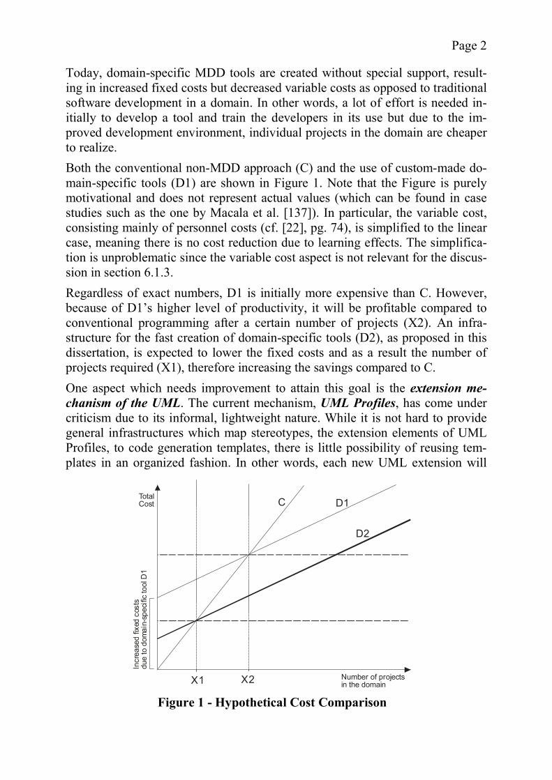
Today, domain-specific MDD tools are created without special support, result-ing in increased fixed costs but decreased variable costs as opposed to traditional software development in a domain. In other words, a lot of effort is needed in-itially to develop a tool and train the developers in its use but due to the im-proved development environment, individual projects in the domain are cheaper to realize. Both the conventional non-MDD approach (C) and the use of custom-made do-main-specific tools (D1) are shown in Figure 1. Note that the Figure is purely motivational and does not represent actual values (which can be found in case studies such as the one by Macala et al. [137]). In particular, the variable cost, consisting mainly of personnel costs (cf. [22], pg. 74), is simplified to the linear case, meaning there is no cost reduction due to learning effects. The simplifica-tion is unproblematic since the variable cost aspect is not relevant for the discus-sion in section 6.1.3. Regardless of exact numbers, D1 is initially more expensive than C. However, because of D1’s higher level of productivity, it will be profitable compared to conventional programming after a certain number of projects (X2). An infra-structure for the fast creation of domain-specific tools (D2), as proposed in this dissertation, is expected to lower the fixed costs and as a result the number of projects required (X1), therefore increasing the savings compared to C. One aspect which needs improvement to attain this goal is the extension me-chanism of the UML. The current mechanism, UML Profiles, has come under criticism due to its informal, lightweight nature. While it is not hard to provide general infrastructures which map stereotypes, the extension elements of UML Profiles, to code generation templates, there is little possibility of reusing tem-plates in an organized fashion. In other words, each new UML extension will
Number of projectsin the domain
TotalCost
Incr
ease
dfix
edco
sts
due
to d
omai
n-sp
ecifi
c to
ol D
1
C D1
D2
X1 X2
Figure 1 - Hypothetical Cost Comparison
Page 3
start over again. At best, code is reused in an unplanned, opportunistic fashion, which negates many of its benefits (cf. [102] or [137]).
1.2 Objectives The main objective of this dissertation is to provide a hierarchical extension mechanism for UML which allows for a more efficient development of code generation modules for a specific domain. The mechanism should enable a de-scription of the domain at different levels of abstraction which can be aug-mented with code generation modules that loosely coupled. In order to address the problems described in the previous section, the extension mechanism must provide concise rules for creating new domains based on previous domains and clear guidelines on how different code generation modules interact. A secondary goal is to evaluate this mechanism by implementing a prototypical code generation environment which can flexibly load hierarchical domain de-scriptions using the extension mechanism. The evaluation should use a problem domain for which MDD is suitable, since the goal of the evaluation is not to find out whether or not the new extension mechanism allows the application of MDD to domains which have proven difficult so far. Rather, it should be shown that the approach integrates smoothly into the existing MDD concepts and that it will reduce the number of steps required for the realization of a new subdomain.
1.3 Chapter Overview This dissertation is organized in the following manner. First, the principles of metamodeling are explained in detail and a clear terminology is established. Metamodeling will be used as a tool to create a hierarchical partitioning of a domain, giving it a central role in the development of the extension mechanism. Next, the model-driven development concepts as found in the current literature are explained and illustrated by examples. The aspired goals of MDD are dis-cussed, leading to a list of shortcomings that will be used to describe which of these goals are realistic. One of the identified shortcomings, the need for an im-proved extension mechanism, is further analyzed, describing existing approach-es and their connection to metamodeling. In chapter 4, the domain of Web applications is analyzed to serve as an example for the implementation. It is shown that the domain is not only suitable for MDD but that it will also profit from the application of model-driven techniques when compared to the current state of Web engineering. The different threads are brought together in the main chapter by introducing a metamodel-based hierarchical extension mechanism for UML and creating an example hierarchy in the Web application domain. Using two models based on the hierarchy, the practical application of the extension mechanism will be ex-plained.
Page 4
The models and the applications generated from them also serve as a basis for an evaluation, which is described in the last chapter. By comparing the developed prototype software with a hypothetical non-hierarchical version of itself, it will be shown that the effort required for the creation of a code generator is reduced by the introduction of a hierarchy. The chapter also addresses some theoretical issues of the chosen approach and discusses related work. It ends with a short conclusion.
1.4 Scientific Contributions This dissertation demonstrates several improvements to the current state of the art in the fields covered. Because of the need for an example domain, not all of the contributions are directly related to the extension mechanism itself. As a contribution to the field of metamodeling, a design space covering the op-tions of metamodeling hierarchy creation is proposed which classifies and eva-luates the choices available when creating a metamodel hierarchy. The options are taken mainly from existing hierarchies but also include new suggestions. The second major contribution is the critical analysis of the goals as well as the state of the art of MDD as currently discussed. It is demonstrated as to which of the suggested approaches can be considered realistic, unrealistic, or outdated. Also, the precursors to MDD are briefly identified and their differences to MDD are explained. This distinction is important yet rarely made in the existing litera-ture on MDD. The core contribution is the definition of the extension mechanism based on metamodeling hierarchies, as well as its critical evaluation. The mechanism is evaluated with a prototypical code generation environment consisting of an Ec-lipse plugin and a Web application framework. The final major contribution is the analysis of the Web application domain to determine the suitability of MDD to its context. Also, by comparing MDD to existing approaches in the Web context, it is shown that MDD offers advantages over the current solutions used for Web Engineering.
Page 5
2 Metamodeling Hierarchies This chapter establishes the basics of metamodeling. Briefly speaking, metamo-dels are models which describe other models, i.e., provide rules for their model instances. According to Albin, every model has a metamodel, although in many cases it is just implicit ([5], Chapter 11). Metamodeling is a wide field; therefore this chapter focuses on those aspects relevant for the domain-specific MDD solution described in chapter 5. It starts with a short description of the motivations for the use of metamodeling followed by some of the relevant standards which exist in this context. The first main sec-tion then describes the rules and concepts of object-oriented metamodeling, es-tablishing a clear and consistent terminology. After that, different variants of metamodeling are presented and evaluated in the context of a newly established design space for metamodel hierarchies. The chapter ends with some conclu-sions. Generally, the definitions and assumptions in this chapter are very pragmatic, especially with regard to language semantics. While formal semantics descrip-tions are very helpful for code generation, the topic of compiler design is consi-dered beyond the scope of this analysis. In section 2.3.2 some arguments are given as to why a less formal approach to semantics is seen as non-problematic in this context. Also, the techniques and models described here are largely inde-pendent of specific software engineering processes which are far too complex to be considered properly in this context.
2.1 Conventional Applications of Metamodeling Metamodeling, especially with multiple layers (see section 2.4.2), is a complex subject. The traditional interpretation of metamodels is that of a language defi-nition, or more precisely, the definition of the syntax of a language (cf. Harel and Rumpe [106], pg. 16). While there are other tools for the definition of mod-eling languages than metamodels such as graph grammars (see [63]), Harel and Rumpe describe metamodels as more intuitive ([106], [107]). A metamodel, combined with a mapping to a semantic domain, is used to represent a system of real-world elements, e.g., a software system. Most model-ing applications leave their users unaware of the details of the metamodel. In fact some users would not even know that they are implicitly using one. In sec-tion 3.5, it will be shown that there are situations where an exposure of the me-tamodel can be useful for the enhancement of software engineering. There are many examples of metamodels used for a variety of modeling purpos-es. Common examples include the Meta Object Facility (MOF) (see section 2.2.2), the Common Warehouse Metamodel (CWM) [163], the Workflow Man-agement Coalition’s (WfMC) metamodel for workflows (see [214] for an over-view), and the Unified Modeling Language (see section 2.2.1).
Page 6
A metamodeling language can be either for a general purpose or it can address a specific domain. A domain-specific modeling language is a modeling language which addresses “domain specific modeling requirements” (cf. Muller et al. [142]). The language usually consists of a metamodel defining a suitable syntax and a mapping to a semantic domain which adequately describes the topic. Do-main specific metamodels are sometimes called reference models. They can be interpreted as a basic decomposition of the problem domain ([5], chapter 11). Domain specific modeling is very popular, e.g., Süß et al. propose a metamodel hierarchy for Web-based teachware with domain-specific models for different fields of teaching such as databases or music [202]. A recent example is the multimedia metamodel proposed by Obrenovic et al. which can be used for con-tent repurposing as well as code generation for multimedia interfaces [156]. Other examples include Nordstrom et al. [154], Völter [208], Albin [5], or Deng et al. [55]. An important aspect of metamodels is that they can be considered models them-selves. In fact, there are some metamodels whose purpose is to allow the defini-tion of other metamodels, in effect languages which allow the description of languages. MOF is the predominant metamodeling language, with MOF 2.0 [169] serving as the metamodel for the UML metamodel. In the context of Mod-el-Driven Development (see chapter 3), the ability to define customized lan-guages has been given new impetus and the ability to provide UML-related va-riant languages is deemed desirable by many (e.g., Duddy [61]). The advantage of custom languages is that they can be designed to specifically address those problems that are most time consuming or difficult. It should be mentioned that metamodeling languages are not the only way of defining custom metamodels. For those unwilling to define a completely new language, UML offers the concept of Profiles, which allows the inclusion of domain-specific model elements into UML diagrams. The profile concept is a lightweight extension mechanism, which has several problems that will be dis-cussed in section 3.5.3.2. The last classical application of metamodels is as an interoperability mechan-ism between different modeling tools. Compatibility problems between different data formats are a common occurrence in the field of information technologies. In the case of applications which operate on the same semantic domain, this in-compatibility is purely a question of syntax and not of content. A standardized metamodel hierarchy allows the interchange of metamodels between applica-tions (cp. section 3.5.4.1). The necessity of metamodel interchange was the main motivation for the birth of the CASE Data Interchange Format (CDIF) standard [40] and the XMI.
Page 7
2.2 Metamodeling Related Standards In the previous section, some of the standards related to metamodeling have al-ready been mentioned as examples. However, those standards later used in chap-ter 5 warrant a closer look. MOF in particular will be used to illustrate the ex-amples throughout this chapter, with further explanation given where required. Other standards, such as CDIF, which are of primarily historical interest, or CWM, which serves purposes largely unrelated to this discussion, will only be mentioned in passing where they offer interesting alternatives to those standards used.
2.2.1 Unified Modeling Language The Unified Modeling Language (UML) [166] is probably the most well-known modeling language in the context of software engineering. As the name implies it is the synthesis of several popular modeling languages which has helped to promote it as a common and widely accepted standard. Also, it is the core modeling language used in the MDA context, especially the mechanism of Profiles which allows users to modify the metamodel to a limited extent. As has already been mentioned, the Profile extension mechanism is too lightweight for most serious applications, as will be discussed in section 3.5.3.2. Other points of criticism against UML are its linear metamodel hierarchy (see section 2.4.1) and its lack of adherence to the principle of strict metamodeling (see 2.4.4) [17]. While most of the following discussion will center on MOF, it is also applicable to UML, since MOF is for practical purposes a subset of UML. Therefore, the details of UML will not be explained here.
2.2.2 Meta Object Facility The OMG’s Meta Object Facility (MOF) standard [160] was originally created for the purpose of providing a foundation for model repositories, as well as for tools which transform MOF models into code. The standard consists of a meta-model, an informal description of its semantics, and rules for a mapping to Common Object Request Broker Architecture (CORBA) Interface Definition Language (IDL) interfaces. The metamodel is practically a subset of UML; a MOF model corresponds roughly to a UML class diagram. Thus it can use the same graphical notations as UML. Many of the MOF/UML concepts, such as the recursive top level definition and the four level metamodel hierarchy, go back to the CDIF standard. MOF is a relatively simple metamodel. According to the standard, the metamo-del at the highest layer is not “a powerful modeling language for expressing a range of information models, it is not intended to be the ultimate modeling lan-guage. Instead, one intended use of the MOF is as a tool for designing and im-plementing more sophisticated modeling systems” ([160], chapter 1 pg. 3). One

Page 8
example for such a language is UML, which can (but need not) be defined in terms of the MOF metamodel. In the case of UML 2.0, MOF is not only one possible metamodel but the primary, official metamodel. CWM is another me-tamodel based on MOF. According to the MOF standard, the MOF metadata architecture has several ad-vantages over earlier metamodeling concepts. First of all, its model is object-oriented, ”aligned with UML’s object modeling constructs“, self-describing, flexible with regard to the number of layers in the metamodel hierarchy, and does not limit its models (in the sense of a collection of metadata) to one meta-level ([160], section 2.2.2). Two statements in this context are of particular interest, i.e., the flexibility with regard to the number of model layers, and the level-spanning nature of models. Both statements imply the suitability of MOF for extended metamodel hierar-chies. However, this is not the case. As will be shown later, the instantiation se-mantics of MOF do not generally allow more than four layers. For the same rea-sons using information of more than one layer is possible but very complex. Later in this chapter (see section 2.3.3), the MOF metamodel will be described in more detail. As has already been mentioned, a MOF model is in principle a UML class diagram. However, MOF is not a perfect submodel of UML due to some minor issues, such as the lack of properly defined semantics for minor de-tails such as visibilities ([160], section 3.6.3). Note that while the latest version of MOF is 2.0 ([165], [169]), only the concepts of MOF 1.4 will be used in the following discussion. While it is true that there are some interesting changes, the MOF has been completely redefined and there is no backwards-compatibility. The other standards based on MOF have yet to catch up with the changes, and discussion on at least one mailing list seems to indicate some dissatisfaction with the alterations. As the related standards are used for the prototypical implementations described later, there is little point in describing an architecture which is incompatible with them. As described above, a MOF repository was intended to be a distributed system accessible via a set of CORBA IDL interfaces. However, since the use of CORBA implies a heavy overhead for any kind of non-distributed repository, the alternative standards described in sections 2.2.3 and 2.2.4 have been devel-oped.
2.2.3 Java Metadata Interface The Java Metadata Interface (JMI) [60] is a Java-based version of the CORBA IDL interfaces defined in the MOF standard. Instead of using remote reposito-ries, the interfaces are intended to allow access to data structures in a Java pro-gram which describe a MOF-based model. The JMI standard is useful because it provides tailor-made Java interfaces for the manipulation of arbitrary metamodel
Page 9
data. This makes it an ideal infrastructure for experiments with newly defined metamodels. There are currently three major implementations, the rather unreliable reference implementation (RI) provided by Unisys, Netbeans’ MetaData Repository (MDR), and the MetaModel Repository (MMR), which is part of SAP’s Net-weaver1. At the early stages of this work, only the first two implementations ex-isted. RI has several technical problems; in fact a simple example model created using the RI-generated interfaces could not be reloaded by RI’s own repository! MDR on the other hand is in a far better state and is actively supported by its programmers via a mailing list. Therefore, MDR was used as JMI implementa-tion for the examples and the prototype.
2.2.4 XML Metadata Interchange The XML Metadata Interchange (XMI) standard [168] is an XML-based data format for the serialization and interchange of MOF-based models. Most com-monly the standard is used with UML models but other applications are also possible. For example, the JMI standard offers a method to serialize arbitrary MOF compliant model data as XMI files. XMI documents for a particular metamodel comply with an XML Schema created based on rules found in the XMI standard. Therefore, the documents of-fer all the advantages inherent to XML, e.g., a universally accepted syntax and human readability. On the down side, XMI documents are overly complex, in some respects redundant, and offer too many variant notation options. Though it appears to be tempting, generating code from XMI files using Extensible Style-sheet Language Transformations (XSLT) [47] scripts becomes a difficult endea-vor for these reasons.
2.3 Core Concepts of Object-Oriented Metamodeling The previous sections have shown how and where metamodeling is currently used. Before metamodeling and its potential beyond the traditional applications can be discussed in detail, it is necessary to establish some core concepts and basic definitions. For this purpose, a terminology is defined in section 2.3.1. The terminology is explicitly limited to object-oriented concepts; while metamode-ling also applies to other paradigms such as Entity-Relationship diagrams, these concepts are irrelevant to the discussion in this dissertation and are therefore omitted. What follows afterwards is a brief description of the semantics of mod-els, which helps understand the intention of models and becomes important for the discussion of the role of metamodels in MDD (see 3.5.4). Finally, in section 2.3.3 a basic metamodeling concept (based on MOF and the model developed by
1 See the JMI home page for details (http://java.sun.com/products/jmi/).
Page 10
Atkinson [21]) is described. These basics can then be used to discuss metamode-ling variants in section 2.4.
2.3.1 Definitions When examining the advanced features of metamodeling, it is easy to become confused due to the similarity of the model layers, the recursive definitions, or one of the other problematic details which will be described in the later sections of this chapter. Therefore, it is helpful to provide simple but meaningful defini-tions in the beginning. Currently, there are a wide variety of terms being used in the research community. In order to establish a basis for the understanding of the further explanations, a list of definitions primarily based on Atkinson’s work (mainly [21]) and MOF is presented. Note that in this context these terms are the only ones used, therefore if cited papers use different ones, these are briefly mentioned but are replaced with the introduced nomenclature for the sake of clarity. Also, even though most of the concepts can easily be applied to other paradigms as well (e.g., Bézivin and Lemesle [31]), object-oriented models are assumed for the sake of simplicity. The definitions are meant to be as pragmatic and technically oriented as possible; more philosophical aspects (cf. the defini-tions provided by Seidewitz [186]) will only be included where appropriate. The definitions are divided into two distinct groups. The first consists of defini-tions which establish the basic concepts found in the metamodeling context. The second are the core terms of metamodeling, which will be defined using the ba-sic concepts. At the end of the section, the definitions used here will be briefly compared to some alternative ones which deviate in more than mere terminolo-gy. 2.3.1.1 Basic Definitions The core concept of metamodeling relies on the terms instance and type or alter-natively instance and template in the terminology of Atkinson [21]. While the origin of these ideas is difficult to determine, they are related to the ontological aspects of Plato’s theory of Forms (cf. [173]).
A type is an abstract concept or category of things. An instance is a concrete occurrence of an element generically described by a type. Thus all instances are structurally and behaviorally identical. An in-stance is said to instantiate its type, the (possibly implicit) connec-tion between the two is called an InstanceOf relationship.
In object-oriented modeling types and instances usually occur in the form of ob-jects, links, classes, associations, and metaclasses. While these concepts are like-ly to be familiar to the reader, a short definition is nevertheless useful to firmly establish them for the following discussion.
An object encapsulates a state, represented by a set of attribute values, and a behavior, represented by a set of methods. Additional-ly, a unique identifier distinguishes it from all other objects. Objects
Page 11
can be considered nodes in a graph. The connecting edge between two objects is called a link. A class is a type which has objects as instances. Its methods and attributes serve as a structural template for the methods and attribute values of its instances. A class can also be an object. Its class is then called a metaclass. An association is a type which has links as instances. Its properties define how many links are allowed and which objects they can con-nect. An association can also be a link. Its association is then called a metaassociation.
2.3.1.2 Metamodeling Definitions Having established the very basic object-oriented metamodeling concepts, it is now time to look at the elements required for a more general view of metamode-ling. This overall concept can be described by the terms model and metamodel.
A model is a collection of objects and links (called model elements) which describe or specify a real world or abstract system. A meta-model is a model which can be used to describe other models. The models described by a metamodel are its instances, the metamodel in return is the type of these models.
The definition hints at two different applications for models. First, a model may be used to describe an existing system, to analyze it in order to postulate on its behavior. Second, it may be used to specify a system (as a sort of blueprint) which has yet to be implemented (cf. Seidewitz [186]). An interesting interpreta-tion offered by Nordstrom et al. is that metamodels describe a modeling para-digm which holds true for the models which are their instances [154]. While it is possible to define additional terms such as metametamodel for meta-models which describe other metamodels (as in done for example in the CDIF standard), it is generally better to simply number metamodel layers and exploit the fact that metamodels can also be models with regard to other metamodels. The following definitions provide the means to uniquely identify all model lay-ers.
A metamodel hierarchy is a tree of models connected by Instan-ceOf relationships. The term model layer or model level describes all (meta-)models with the same distance to the root metamodel in a metamodel hierarchy. Each level is given a unique name, often con-taining a number.
The most common naming practice for model layers is a letter combined with a number index, e.g., M1. The letter M is the typical choice in the MOF and UML context (cp. [160]). However, in more complex metamodel hierarchies it is use-ful to use different letters to identify different types of layers. An example of this practice will be shown in section 2.4.1. Also, it should be noted that most
Page 12
hierarchies examined in this chapter will have only one model per layer, so sometimes a model is identified by the name of its layer. So far, the relationships between a metamodel and a model have been left inten-tionally generic. In fact, these relationships can differ from hierarchy to hie-rarchy. For a concrete application, they have to be specified via instantiation semantics. The semantics of instantiation, which can vary widely, are defined in the following way:
Instantiation Semantics are a set of rules associated with a type. All instances of the type must comply with these rules.
Instantiation semantics are rarely considered in papers on metamodeling. Atkin-son and Kühne [19] were among the first to identify the concept, though without offering a formalized definition. The choices made regarding the instantiation semantics have a strong influence on the nature of the model hierarchy (see sec-tion 2.4.3). As a side note, it is debatable, whether instantiation semantics are part of the semantics or part of the syntax. This subject will be briefly discussed in section 2.3.2, however, in order to comply with already-established terminol-ogy, the term ‘instantiation semantics’ will be used anyway. The connection established by instantiation semantics forms a relationship be-tween model layers. Riehle et al. introduce the term causal connection to de-scribe this relationship between metalayers and layers:
A modeling level is causally connected with the next higher model-ing layer, if the lower layer conforms to the higher level and if the changes in the higher level lead to respective changes in the lower level [176].
Therefore, if instantiation semantics are specified, a strong and formalized caus-al connection is established. The causal connection is required for models to be validated and interpreted. 2.3.1.3 Comparison With Alternative Definitions The diversity of different interpretations of metamodeling has already been men-tioned. While most variations are merely of a terminological nature, there are also some approaches which are conceptually different. Since a clear choice of definitions has already been made, these alternatives are of only minor interest. However, several examples are provided together with arguments on why they were not chosen as a basis for this work. Of particular importance are two pa-pers by Seidewitz ([186], [187]) as they are the result of a lengthy discussion with many members of the OMG involved in the UML 2.0 proposals. The terms model and, to a lesser extent, metamodel are used in many contexts and therefore have been defined in many different ways. Even when limiting oneself to the field of computer science, there are still many different defini-tions. Seidewitz defines a model as a “set of statements about some system un-der study” [186] and a metamodel as a “specification model for a class of [sys-
Page 13
tems under study] where each [system under study] in the class is itself a valid model expressed in a certain modeling language” [186]. While the theoretical foundation provided by Seidewitz is a basis useful for some arguments in favor of certain metamodeling choices and at a superficial glance does not appear to differ from the definitions chosen for this dissertation, it is too complex to assist in understanding the basics of metamodeling theory. Also, the definitions pro-vided in section 2.3.1 are far more pragmatic and oriented towards an implemen-tation of data structures for handling metamodel hierarchies, whereas those of Seidewitz are wider and less tangible. As the theory described in this chapter is meant to serve as a basis for the description of the prototype in chapter 5, the provided definitions are therefore more suitable. Albin describes a metamodel as a “set of instructions for creating an instance of a class of models.” which makes a metamodel a “domain-specific, self-contained design ontology” ([5], chapter 11). This definition was not used be-cause it closely ties metamodeling to domains and ontologies. While this view definitely has its merits, it makes the terminology more confusing, for example with regard to the distinction of ontological and linguistic metamodels in section 2.4.1. In the previous section, the term instantiation semantics has been introduced. It has already been mentioned that this term is rarely used and that the concept be-hind it is often (but not always) implicitly assumed rather than explicitly de-fined, even though instantiation semantics provides a strong causal connection between the model layers. Seidewitz, however, is of the opinion that such a strong connection does not exist, stating that the “concept of ‘instance_of’ has meaning only within the theory of the metamodeling language [and] not between a metamodeling-language element […] and a modeling language-element” ([186], emphasis added). This assumption is reasonable based on the definitions Seidewitz provides and his separation between metamodel and modeling language. Naturally, Seidewitz is not opposed to a connection between the two concepts but rather believes it to be nonexistent in current versions of UML or MOF, leading to problems where its existence is implicitly assumed [186]. With regard to MOF 1.x, this statement is debatable. While it is true that in UML an “instance_of” relationship is de-fined which does not exist in MOF 1.x, and that there is of course no such rela-tionship possible between model layers (cp. 2.4.4), the MOF standard provides enough information to talk about a strong logical interdependency. In fact, the standard dedicates a whole chapter to the definition of the instantiation seman-tics. Seidewitz is somewhat vague in his criticism and it is hard to understand why he views this as a deficiency.
2.3.2 Model Semantics The importance of model semantics cannot be stressed enough. The vagueness found in the context of metamodeling terminology is even worse when it comes
Page 14
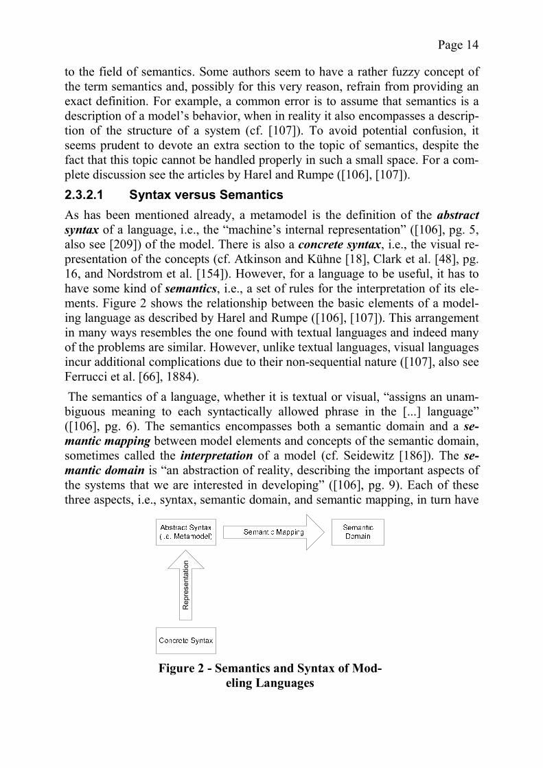
to the field of semantics. Some authors seem to have a rather fuzzy concept of the term semantics and, possibly for this very reason, refrain from providing an exact definition. For example, a common error is to assume that semantics is a description of a model’s behavior, when in reality it also encompasses a descrip-tion of the structure of a system (cf. [107]). To avoid potential confusion, it seems prudent to devote an extra section to the topic of semantics, despite the fact that this topic cannot be handled properly in such a small space. For a com-plete discussion see the articles by Harel and Rumpe ([106], [107]). 2.3.2.1 Syntax versus Semantics As has been mentioned already, a metamodel is the definition of the abstract syntax of a language, i.e., the “machine’s internal representation” ([106], pg. 5, also see [209]) of the model. There is also a concrete syntax, i.e., the visual re-presentation of the concepts (cf. Atkinson and Kühne [18], Clark et al. [48], pg. 16, and Nordstrom et al. [154]). However, for a language to be useful, it has to have some kind of semantics, i.e., a set of rules for the interpretation of its ele-ments. Figure 2 shows the relationship between the basic elements of a model-ing language as described by Harel and Rumpe ([106], [107]). This arrangement in many ways resembles the one found with textual languages and indeed many of the problems are similar. However, unlike textual languages, visual languages incur additional complications due to their non-sequential nature ([107], also see Ferrucci et al. [66], 1884). The semantics of a language, whether it is textual or visual, “assigns an unam-biguous meaning to each syntactically allowed phrase in the [...] language” ([106], pg. 6). The semantics encompasses both a semantic domain and a se-mantic mapping between model elements and concepts of the semantic domain, sometimes called the interpretation of a model (cf. Seidewitz [186]). The se-mantic domain is “an abstraction of reality, describing the important aspects of the systems that we are interested in developing” ([106], pg. 9). Each of these three aspects, i.e., syntax, semantic domain, and semantic mapping, in turn have
Rep
rese
ntat
ion
Figure 2 - Semantics and Syntax of Mod-eling Languages
Page 15
to be described in some sort of language, leading in effect to a cascading set of recursions. Due to their different natures, the three aspects require different types of lan-guages. For example, the semantic domain can use, among other things, natural language or mathematical expressions, the abstract syntax can be defined using a graphical notation, and the semantic mapping by any language which contains the other two languages as a subset (cp. [107]). As the semantic mapping has to provide a logical connection between all possi-ble syntactically correct constructs and the corresponding elements in the se-mantic domain, defining a mapping typically is a very complex task. While it is possible to use some form of compositional semantics, i.e., to use already de-fined mappings as a basis for mappings involving the same syntactic elements, Harel and Rumpe state that such an approach is not always possible. For this and other reasons many modeling languages are based on a semantic mapping, which is only informally described by giving examples and general descriptions instead of a formal definition [107]. However, in practical applications the boundary between syntax and semantics is sometimes perceived as nebulous. Harel and Rumpe complain that context conditions, i.e., constraints on which “sentences” are syntactically correct, are often called “semantic conditions” even though they do not define any semantics ([106]. pg. 14). The instantiation semantics as defined in the previous section also fit into this category, limiting the number of syntactically correct models but not providing any kind of meaning. Therefore, a different name would be more appropriate. It should also be mentioned that the definition provided by Harel and Rumpe is not universally accepted and not all other approaches can be necessarily be con-sidered false. For example, Clark et al. consider the semantics to be part of the metamodel, since a metamodel without semantics is meaningless ([48], pg. 19 and pg. 25). Also, there are other formal specification techniques for visual languages. Tortora for example proposes a formal definition of an iconic pro-gramming language as a triple of icon dictionary, grammar, and domain-specific knowledge base [205]. 2.3.2.2 A Pragmatic Approach to Semantics The explanations of the previous section illustrate the complexity inherent in the definition of a precise semantics and for these reasons no attempt is made to provide a fully-fledged semantic mapping in the context of this dissertation. The more pragmatic solution, which will be used in chapter 5, is to define semantics by mapping to a programming language (cf. Völter [209]), for example, by de-fining templates for each model element. This could be described as piggy-backing the models onto the semantics of the programming language.
Page 16
While such a “short-cut” is not an entirely satisfactory solution, it is possible to argue in favor of a less formal semantic definition in this context. According to Harel and Rumpe, the degree of formalism largely depends on the intended tar-get audience. While tool vendors require a high degree of formalism, especially for code generation, end users will usually prefer less precise but more readily understood descriptions ([106], pp. 21-22). In the context of this dissertation, however, there is no need to provide a formal definition for a tool vendor and such a definition is therefore considered future work.
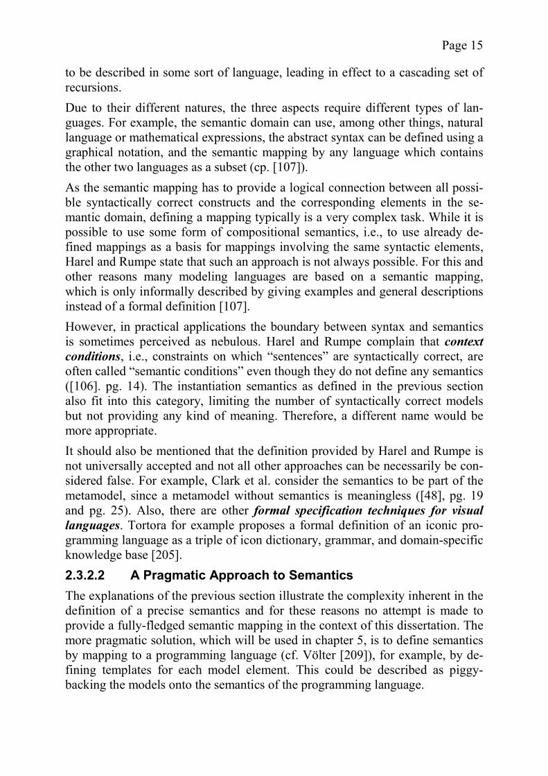
2.3.3 Principles and Examples Using the definitions established in the two previous sections, several examples explaining the principles of object-oriented metamodeling can be constructed. The notation chosen for all examples is the subset of UML used in the MOF standard ([160], section 3.1) with the addition of a non-standard InstanceOf re-lationship to explain the inter-layer connections. The first two examples describe the core concepts of MOF which bring up the problem of the model/metamodel dualism. After explaining the inherent prob-lems of the dualism, the main elements of MOF, class and association, and their instantiation semantics are described. 2.3.3.1 Core Elements of MOF Figure 3 shows an example MOF-based metamodel (M1) and a possible in-stance (M0). The types and their instances are connected by InstanceOf relation-ships. Goya is an instance of the class Painter and is connected by links to his paintings, which are in turn instances of Painting. The instantiation semantics conform to the general object-oriented paradigm.
+DateOfBirth : StringPainter Painting
* *
Creation
InstanceOf
InstanceOf
InstanceOfInstanceOf
InstanceOf
M0
M1
DateOfBirth : String = "March 30, 1746"Goya : Painter
The Naked Maja : Painting
Charles IV and his Family : Painting
Figure 3 - Example MOF Elements
Page 17
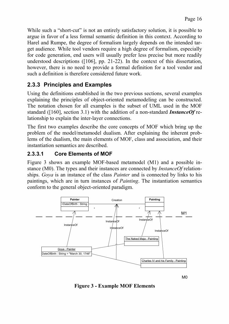
The M1 level shown in the Figure is only one example of a possible MOF-based metamodel. In other words, the metamodel M1 of M0 can also be interpreted as a model of a layer M2 (not shown) which contains the MOF metamodel. Before moving on to the metalevel M2, it is helpful to establish the following notational convention: The names of classes and associations such as Painter or Creation are capitalized and written in italics. This makes it easier to distinguish between a class called Association and an actual association. While the necessity of this convention might be unclear at the moment, it will become obvious when looking at the next examples. Figure 4 removes the M0 layer from the example above and instead shows the M2 layer, which contains the MOF metamodel. Two interesting facts can be dis-cerned when combining the information found in both Figures. First, the instan-tiation semantics of an M1 element is influenced by its M2 type. A Painter uses the instantiation semantics of a class, because it is an instance of Class, Creationuses the instantiation semantics of an association, because it is an instance of Association. Second, there seems to be a mismatch between the M2 types and their M1 instances. For example, an Association instance must contain two As-sociationEnd instances, however, in the M1 layer, these are not explicitly shown. This phenomenon can be attributed to the model/metamodel dualism de-scribed next. 2.3.3.2 The Model/Metamodel Dualism The reason why the M1 level in Figure 4 does not seem to match its metamodel in layer M2 is that there are two possible views on a metamodel at any level of a MOF hierarchy. This dualism is one of the most complicated aspects of MOF, as it is not immediately obvious from the specification. Several researchers have
Figure 4 - Core Elements of MOF
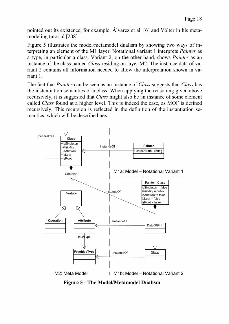
Page 18
pointed out its existence, for example, Álvarez et al. [6] and Völter in his meta-modeling tutorial [208]. Figure 5 illustrates the model/metamodel dualism by showing two ways of in-terpreting an element of the M1 layer. Notational variant 1 interprets Painter as a type, in particular a class. Variant 2, on the other hand, shows Painter as an instance of the class named Class residing on layer M2. The instance data of va-riant 2 contains all information needed to allow the interpretation shown in va-riant 1. The fact that Painter can be seen as an instance of Class suggests that Class has the instantiation semantics of a class. When applying the reasoning given above recursively, it is suggested that Class might also be an instance of some element called Class found at a higher level. This is indeed the case, as MOF is defined recursively. This recursion is reflected in the definition of the instantiation se-mantics, which will be described next.
+isSingleton+Visibility+isAbstract+isLeaf+isRoot
Class
Feature
Operation Attribute
Contains
Generalizes
+DateOfBirth : StringPainterInstanceOf
M1a: Model – Notational Variant 1
M1b: Model – Notational Variant 2M2: Meta Model
InstanceOf
InstanceOf
PrimitiveType
IsOfType
InstanceOf
isSingleton = falseVisibility = publicisAbstract = falseisLeaf = falseisRoot = false
Painter : Class
DateOfBirth
String
Figure 5 - The Model/Metamodel Dualism
Page 19
2.3.3.3 Class Instantiation Semantics Figure 4 and Figure 5 illustrate several examples of instantiation, some of which have already been informally discussed. An interesting aspect of MOF is that the instantiation semantics are always based on an element’s type, i.e., Painter has the instantiation semantics of a class, because it is an instance of Class. In the standard the transitivity of the definition is not mentioned explicitly. The state-ment that an “M1-level Instance is a value whose type is described by an M2-level Class” ([160], section 4.5) is slightly misleading. More accurately, it should be described the following way: An M1-level instance is a value whose type is described by an M2-level instance of M3 Class. The MOF core semantics for class instantiation (i.e., the instantiation of model elements which in turn are instances of Class) can be summarized in the follow-ing way (cf. [160] sections 4.5 and 4.6):
The instance has an object identity which is in no way reliant on its attribute values.
The instance belongs to the computational context known as the class ex-tent.
The attributes of the instance are defined by M2-level attributes. The name and type provide the basic signature for the relationship between the instance and the attribute value (often an instance of a M1 primitive data type).
The instance can be linked to other instances via links. An M1 instance of an M2 Class cannot have instances if its isAbstract
attribute has the value true. Informally, these rules lead to the behavior of class instantiation known from the UML context. The object Goya in the example has an object ID (not shown), belongs to the extent of all Painter instances, and has a single attribute slot which links to a string value. Its participation in links is governed by the asso-ciations defined for Painter. 2.3.3.4 Association Instantiation Semantics Figure 6 shows the instantiation of an Association. Again, there are two ways to interpret the M1 layer shown here as variant 1 and 2. Association is one of the more complex and possibly sub-optimally defined elements in the MOF hie-rarchy. For instance, Association’s position in the inheritance hierarchy of MOF is counter-intuitive. Due to this poor design choice many unneeded properties, such as the participation in the Generalizes association or the ability to contain arbitrary elements, are inherited and have to be forcibly suppressed by con-straints.

Page 20
For these and other reasons, the Figure shows only a simplified form of the MOF definition which nevertheless has the same semantics as the original. For example, many attributes are omitted as is most of the inheritance hierarchy. Since both Class and Association inherit the Contains relationship from Names-pace, this association appears twice in the Figure. The Contains relationship for Association has been explicitly limited to AssociationEnds. In the standard the same effect is obtained by constraints. The notational variant 2 shows us that an Association is defined primarily by its endpoints, i.e., instances of AssociationEnd. These endpoints determine such factors as navigability, aggregation, and multiplicities, which are concepts all very similar or identical to those found in UML. The ‘type’ of the endpoint (as determined by the IsOfType Association instances) identifies the type of the va-lid nodes the link can connect to.
M1a: Model – Notational Variant 1
M1b: Model – Notational Variant 2M2: Meta Model
Association
+isNavigable+Aggregation+Multiplicity+isChangeable
AssociationEnd
Class
FeatureReference
Contains
IsOfType
RefersTo
Contains
Painter
Painting
1..*
1..*
Creation
InstanceOf
Creation : Association
isNavigable = trueAggregation = noneMultiplicity = 1..*isChangeable = true
End1 : AssociationEndisNavigable = trueAggregation = noneMultiplicity = 1..*isChangeable = true
End2 : AssociationEnd
Painter Painting
Reference1 Reference2
Figure 6 - Instantiation Semantics of Association

Page 21
A curious fact found in the Figure is that Association and AssociationEnd are instances of Class. Therefore, the instantiation semantics of class introduced in the previous section are used to determine the look of notational variant 2. In-stances of Creation, on the other hand, use the instantiation semantics of associ-ation, since their type is Association. It might be surprising that AssociationEnduses an association to identify the allowed classes at its end. This arrangement is far from intuitive and it usually takes some time to understand the details of these design choices. The most important aspect of the instantiation semantics which apply to MOF Associations are given below (see [160], section 4.9):
A MOF M2 level instance of Association defines a binary relationship be-tween pairs of the M1-level instances of the M2 level instances of Class,which are allowed by its AssociationEnds. These relations are called linksand are grouped in a link set (effectively an extent for links). The link set is a subset of the Cartesian product of the two sets of instances of the M2 types allowed as endpoints by the two AssociationEnds.
Thus a link, which is a member of the link set, can be any tuple of the form “<c1, c2>” where “c1” and “c2” are members of the two sets of al-lowed endpoints.
The link set must adhere to the rules specified for multiplicities, unique-ness etc. in the Association instance.
To go back to the example, instances of Creation will be part of the link set for Creation which ensures that its links do not violate the rules specified in the As-sociationEnd instances End1 and End2 which are contained in the namespace of Creation. While there are other elements in the MOF metamodel, the understanding of class and association instantiation semantics is sufficient to understand the fol-lowing reasoning about metamodel hierarchies and the descriptions of the proto-type. In the next section, the MOF concepts are compared to other metamode-ling approaches, establishing a design space for metamodel hierarchies.
2.4 A Design Space for Metamodel Hierarchies While MOF and UML are the most commonly used metamodel hierarchies, there are also other approaches (for an overview see Atkinson [21]). Even within the group based on object-oriented modeling, there is enough deviation to pre-vent the definition of a universal structure underlying all metamodel hierarchies. In fact, there are several possible choices which have different advantages and drawbacks and thus are suitable for different purposes. In this section these choices are identified by discussing several variants and extensions to the simple metamodel hierarchy described in the previous subsections, effectively creating a design space of different value combinations (cf. Herbleb and Mockus [112]).
Page 22
Since the design options discussed in this section result in different metamodel hierarchy properties, it is necessary to find a common frame to identify which of the options are suitable for a specific situation. However, it is difficult to come up with a list of quality criteria without the concrete definition of a goal. Thus, an applicable yet sufficiently abstract quality concept has to be identified. Start-ing with the goal of cost reduction, it is possible by successively partitioning to eventually create the desired list of quality criteria. There are two qualities of a metamodel hierarchy which help reduce the cost in-volved in its use. These are a general applicability of a hierarchy and its ease-of-use at all levels of abstraction. While there are other aspects which further the goal of cost reduction, good arguments can be brought forth for using these two subgoals as a basis for an evaluation of the different metamodeling variants. First of all, a metamodel hierarchy infrastructure is complex. A generally appli-cable solution is by far preferable to any custom-made framework because both the creation and the maintenance of complex software are costly. Second, a me-tamodel hierarchy has to be maintained at all of its levels at different points of time which means that it has to be easily usable in all these contexts, otherwise more time (and money) than necessary will be required. The next refinement step leads to the list of quality criteria used for evaluation. While it would be possible to include “obvious” technical criteria such as the existence of machine-readable formats for the models, these details are already part of all major metamodeling frameworks like MOF/JMI. Therefore, they are considered to be forming an existing infrastructure and are not discussed here. Rather, this section will focus on criteria which better reflect the quality of dif-ferent design options. A good criterion for the ease of use of a metamodel hierarchy is its complexity. Generally, if the complexity of a hierarchy is high, it will not be easy to use and therefore will be more error-prone than a less complex variant. A typical sign of high complexity is the replication of concepts which Atkinson and Kühne define in the following way:
If a modeling element from any layer in a metamodel hierarchy is re-produced on a lower layer, the hierarchy contains a replication of concepts [19].
A replication of concepts negatively influences the complexity of a model in two ways. First of all, with additional elements, the model size is increased unneces-sarily, making it harder to understand. Second, inconsistencies might be intro-duced, if the replicated concepts are accidentally implemented differently in each case (cf. Atkinson and Kühne [19]). While such a model is still “technical-ly correct”, it is harder to use, because each layer might potentially have its own “dialect”. Thus, a replication of concepts also has a negative impact on another important criterion for the ease-of-use of a metamodel hierarchy, its consistency. A lack of

Page 23
consistency will make it difficult to use the hierarchy, because of errors or the need to look up definitions in order to find the correct approach to modeling a certain aspect of the domain. Another consistency problem identified by Atkin-son and Kühne is ambiguous classification:
A metamodel hierarchy is called ambiguously classified or as suf-fering from ambiguous classification, if there exists an instance which has more than one type [19].
However, not all researchers agree on the thesis that ambiguous classification poses a problem. For example, Seidewitz states that “a single modeling language might have more than one metamodel, with each expressed in a different model-ing language” ([186], pg. 29). Obviously, each instance in the model must have a type in each of the metamodels and thus it is ambiguously defined according to the definition provided above. On the other hand, the definition of ambiguous classification might be interpreted as referring to several types per metamodel, seeing the types in other metamodels as part of alternative model hierarchies. For the discussion in this section, the latter point of view is adopted and ambi-guous classification is used as an indicator of inconsistency. A third property affecting both applicability and ease-of-use of a metamodel hie-rarchy is its expressional strength. A great expressional strength not only allows the modeling of a wide range of domains, but it also encompasses the ability to present information at different levels of abstraction. While some might argue that this criterion is in conflict with that of model complexity, it can be reasoned, based on the design decisions described in section 2.4.7, that an increase in ex-pressional strength does not automatically increase the model complexity and vice versa. The degree of extensibility of a metamodel hierarchy influences its applicability to a wide range of problems. Only if it is possible to add new elements, a wide range of yet unforeseen problems can be covered by the modeling language. Therefore, the extensibility forms another important evaluation criterion. A criterion closely related to extensibility is robustness to change, which re-flects how much impact a genuine change as opposed to a mere extension has on the instances of the hierarchy. While it could be considered a manifestation of robustness to change, extensibility is generally easier to achieve than a general robustness to change. Therefore, the two criteria are addressed separately. The following sub-sections will look at several options available when designing an object-oriented metamodel hierarchy. While not all quality criteria are appli-cable in all cases, the impact of a design decision on the overall quality of the hierarchy will be briefly discussed in each case.
2.4.1 Linear Versus Nonlinear Metamodel Hierarchies One of the fundamental decisions in metamodeling is whether to use a tradition-al linear metamodel hierarchy or a more advanced nonlinear metamodel hie-
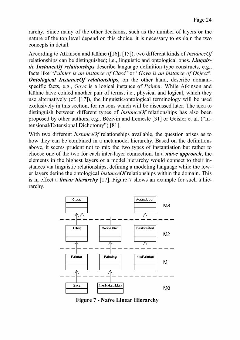
Page 24
rarchy. Since many of the other decisions, such as the number of layers or the nature of the top level depend on this choice, it is necessary to explain the two concepts in detail. According to Atkinson and Kühne ([16], [15]), two different kinds of InstanceOfrelationships can be distinguished; i.e., linguistic and ontological ones. Linguis-tic InstanceOf relationships describe language definition type constructs, e.g., facts like “Painter is an instance of Class” or “Goya is an instance of Object“. Ontological InstanceOf relationships, on the other hand, describe domain-specific facts, e.g., Goya is a logical instance of Painter. While Atkinson and Kühne have coined another pair of terms, i.e., physical and logical, which they use alternatively (cf. [17]), the linguistic/ontological terminology will be used exclusively in this section, for reasons which will be discussed later. The idea to distinguish between different types of InstanceOf relationships has also been proposed by other authors, e.g., Bézivin and Lemesle [31] or Geisler et al. (“In-tensional/Extensional Dichotomy”) [81]. With two different InstanceOf relationships available, the question arises as to how they can be combined in a metamodel hierarchy. Based on the definitions above, it seems prudent not to mix the two types of instantiation but rather to choose one of the two for each inter-layer connection. In a naïve approach, the elements in the highest layers of a model hierarchy would connect to their in-stances via linguistic relationships, defining a modeling language while the low-er layers define the ontological InstanceOf relationships within the domain. This is in effect a linear hierarchy [17]. Figure 7 shows an example for such a hie-rarchy.
Figure 7 - Naïve Linear Hierarchy
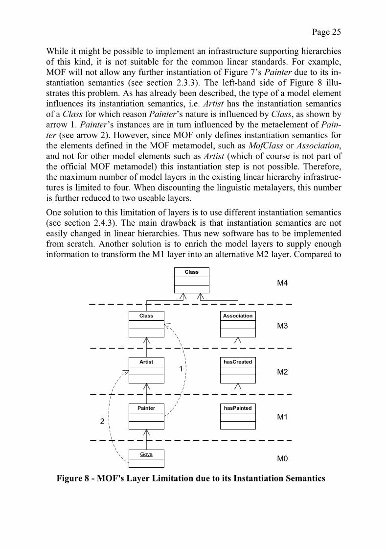
Page 25
While it might be possible to implement an infrastructure supporting hierarchies of this kind, it is not suitable for the common linear standards. For example, MOF will not allow any further instantiation of Figure 7’s Painter due to its in-stantiation semantics (see section 2.3.3). The left-hand side of Figure 8 illu-strates this problem. As has already been described, the type of a model element influences its instantiation semantics, i.e. Artist has the instantiation semantics of a Class for which reason Painter’s nature is influenced by Class, as shown by arrow 1. Painter’s instances are in turn influenced by the metaelement of Pain-ter (see arrow 2). However, since MOF only defines instantiation semantics for the elements defined in the MOF metamodel, such as MofClass or Association, and not for other model elements such as Artist (which of course is not part of the official MOF metamodel) this instantiation step is not possible. Therefore, the maximum number of model layers in the existing linear hierarchy infrastruc-tures is limited to four. When discounting the linguistic metalayers, this number is further reduced to two useable layers. One solution to this limitation of layers is to use different instantiation semantics (see section 2.4.3). The main drawback is that instantiation semantics are not easily changed in linear hierarchies. Thus new software has to be implemented from scratch. Another solution is to enrich the model layers to supply enough information to transform the M1 layer into an alternative M2 layer. Compared to
Class
Artist
Painter
Association
hasCreated
hasPainted
M3
M2
M1
GoyaM0
Class
M4
1
2
Figure 8 - MOF's Layer Limitation due to its Instantiation Semantics
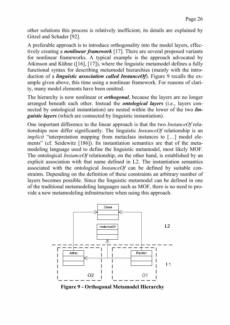
Page 26
other solutions this process is relatively inefficient, its details are explained by Gitzel and Schader [92]. A preferable approach is to introduce orthogonality into the model layers, effec-tively creating a nonlinear framework [17]. There are several proposed variants for nonlinear frameworks. A typical example is the approach advocated by Atkinson and Kühne ([16], [17]), where the linguistic metamodel defines a fully functional syntax for describing metamodel hierarchies (mainly with the intro-duction of a linguistic association called InstanceOf). Figure 9 recalls the ex-ample given above, this time using a nonlinear framework. For reasons of clari-ty, many model elements have been omitted. The hierarchy is now nonlinear or orthogonal, because the layers are no longer arranged beneath each other. Instead the ontological layers (i.e., layers con-nected by ontological instantiation) are nested within the lower of the two lin-guistic layers (which are connected by linguistic instantiation). One important difference to the linear approach is that the two InstanceOf rela-tionships now differ significantly. The linguistic InstanceOf relationship is an implicit “interpretation mapping from metaclass instances to […] model ele-ments” (cf. Seidewitz [186]). Its instantiation semantics are that of the meta-modeling language used to define the linguistic metamodel, most likely MOF. The ontological InstanceOf relationship, on the other hand, is established by an explicit association with that name defined in L2. The instantiation semantics associated with the ontological InstanceOf can be defined by suitable con-straints. Depending on the definition of these constraints an arbitrary number of layers becomes possible. Since the linguistic metamodel can be defined in one of the traditional metamodeling languages such as MOF, there is no need to pro-vide a new metamodeling infrastructure when using this approach.
Figure 9 - Orthogonal Metamodel Hierarchy
Page 27
An interesting aspect in Figure 9 is that some of the model elements seem to have two types; Painter for example is instance of Class and Artist. For this rea-son, in an earlier paper, Atkinson and Kühne identify ambiguous classification as a potential problem of this approach [19]. This problem is, in my opinion, a rather subtle one and depends largely on the interpretation of the model hie-rarchy. If a clean separation of the linguistic and ontological models exists, the linguistic classes can simply be omitted, adopting a purely ontological view of the model. With the linguistic metamodel adopting the role of a description lan-guage for the ontological hierarchy, there is no longer any ambiguity as apparent in the Figure. This view is the one used as a basis for the discussion of the non-linear approaches later in this section. The clear separation between linguistic and ontological concepts provided by a nonlinear hierarchy as presented so far is appealing but is not inherent to non-linear metamodeling. For example, Riehle et al. [176] provide a comparable di-vision between a logical architecture and a physical architecture. However, the physical architecture is very limited and the logical layer also contains elements which are “linguistic” in the sense described above. This deviation is due to the fact the physical layer is not intended to provide the syntax for ontological me-tamodel hierarchies but to provide the infrastructure for a UML virtual ma-chine. Thus, the complete traditional UML metamodel is reproduced on the log-ical level. Álvarez et al. [6] propose to use a metamodel which contains classes called Class and Object. These can then be used to model a 2-layered logical hie-rarchy. As the upper layer of the two effectively is a metamodel, it can replicate the physical metamodel and again model a 2-layered hierarchy, effectively nest-ing the orthogonality seen in Figure 9 several times within itself. The main drawback of this approach is that there is a massive replication of concepts, as each metamodel has to provide its own “linguistic” features. Also, the division between linguistic and ontological modeling is blurred. In the light of these two examples, it seems advisable to refine the definitions used so far. While the concepts of ontological and linguistic instantiation can be associated with the physical and logical architectures identified by Álvarez et al., each division in my opinion emphasizes slightly different aspects. Even though they use the terms physical/logical modeling and linguistic/ontological modeling almost interchangeably (cf. [17] and [16]), Atkinson and Kühne are aware of this discrepancy. In fact they admit the possibility of interpreting the “On level as defining a language to be used in On-1” [15], which “sounds linguis-tic” but is logical instantiation (which is seen as synonymous to ontological modeling). For the remainder of this dissertation, the concepts are separated in the following way:
A physical metamodel is a metamodel which is described in the form of program code and data structures. Physical instances are described by a program state but can be serialized in an appropriate

Page 28
data format or, if interpreted as metamodels themselves, can be used to generate the program code required for the physical meta-models corresponding to the instances.
A good example can be found in the context of MOF or, more specifically, JMI, which uses a physical metamodel. Naturally, a physical metamodel can be used to describe a logical metamodel hierarchy.
A logical metamodel is a subset of the elements of the physical in-stance of a special physical metamodel and is therefore stored as program state. The logical instances are part of the same physical instance as their metamodel. A logical instance can be used as a metamodel without generating any program code by instantiating the appropriate elements of the physical metamodel.
Physical models are easier to use by programmers as they are accessible via stat-ically typed interfaces, thus providing less of an “intellectual burden” [176]. On the other hand, they are less flexible with regard to model layers, the number of which is unconstrained only in the case of logical metamodels (cf. [17]). As an interesting side note, Atkinson and Kühne consider stereotypes (see section 3.5.3.2) “shorthand syntax for logical metamodeling” [17]. The other axis is to distinguish between different purposes for instantiation, ei-ther to define the syntax of a language or to describe ontological relationships. The two purposes are not completely separable. In fact it might be argued that ontological metamodeling is a subset of linguistic metamodeling, defining do-main-specific languages. However, in this context the definition of linguistic metamodeling is limited to those cases which are not ontological in order to provide a clear separation.
Linguistic metamodeling is the technique of using a metamodel to describe a domain-neutral language syntax which serves as a basis for the creation of ontological metamodels. Ontological metamode-ling is the technique of using a metamodel to describe a syntax suit-able for a semantic mapping to a specific domain. An ontological me-tamodel can be either based on a linguistic or another, more abstract ontological metamodel.
While an ontological metamodel seems to imply domain-specific semantics, it is important to point out again that a metamodel is a purely syntactical construct and therefore does not define any kind of semantics (see section 2.3.2). Howev-er, the elements in an ontological metamodel can be designed to make the se-mantic mapping easier and more intuitive for the human reader, due to sugges-tive model element names. With the changed definitions we can better describe the relationship between the different axes of metamodeling. A physical metamodel, for example, is almost always a language definition but can have some ontological aspects (see CWM [163] for example). Logical metamodeling is often ontological but in the case of

Page 29
Riehle et al. [176] and Álvarez et al. [6] as described above, it can also be lin-guistic. The decision whether to use a linear or a nonlinear metamodel hierarchy is not necessarily straightforward. For the criterion of model complexity from the be-ginning of the section to be applied, two cases have to be distinguished. There are small hierarchies with few layers and larger hierarchies in which several lay-ers are actively used on a general basis. Thus, in the context of this discussion, UML would be considered a small hierarchy, since only 2 of its layers (the model layer and the metamodel layer which can be extended through stereo-types) are really relevant for its typical use as few people have the need to change the higher layers. Since a nonlinear hierarchy involves a certain over-head due to its linguistic metamodel, it will cause a greater model complexity than linear hierarchies for small hierarchies. In larger hierarchies, on the other hand, linear hierarchies grow exuberantly as certain infrastructural elements have to be replicated on each layer. Regarding the expressional strength of both approaches, it is hard to make a general statement. In any ontological hierarchy the metatypes of an element can add useful information and provide a more abstract view of a model. For exam-ple, going back to Figure 7, the fact that a Painter is an instance of Artist can be used for a more abstract view which does not distinguish between the different forms of art. On the other hand, linguistic instantiation does not benefit from this shifting of layers; the fact that hasPainted is a Class at the level M4 (not shown in the Figure) provides little useful information. Since nonlinear frameworks are more suitable for ontological hierarchies spanning multiple layers, it might be argued that the expressional strength of nonlinear approaches is higher than that of linear ones when ignoring the impact of other design choices. Generally, the consistency of nonlinear hierarchies will be higher, because each ontological layer will use the same linguistic elements while each layer of a li-near hierarchy involves a completely new language definition. This can lead to some bizarre situations, such as associations being instances of classes (as is the case in the MOF). While the Association as instance of Class is commonly ac-cepted and makes sense in the context of MOF, objectively speaking such an arrangement might very well be considered an inconsistency. Also, as with any replication of concepts, inconsistencies might appear between the layers. Linear approaches offer a good degree of extensibility. For example, UML can be extended using Profiles. The same applies to nonlinear hierarchies which can easily be edited at any level. The robustness to change, however, largely de-pends on other factors. Besides these criteria, it can be said that nonlinear metamodel hierarchies are helpful if more than two non-linguistic metalayers are required or non-standard instantiation semantics are to be implemented. While ontological metamodeling does not explicitly require a nonlinear hierarchy, it can benefit from this in-
Page 30
creased degree of freedom. Conversely, pure language definitions with little need for multiple metalevels can profit from the simplicity of linear hierarchies. While in the context of current metamodeling applications, linear models seem to prevail, nonlinear metamodel hierarchies as a combination of physical and logical modeling are not as exotic as they might seem. However, logical instan-tiation often occurs only in the lowest layer. For example, the UML 2.0 meta-model can describe both classes (as elements of a class diagram) and objects (as elements of an object diagram) in the same layer, yet their instantiation relation-ship is purely logical. A similar logical instantiation relationship is proposed by Geisler et al. [81]. The benefit of such a construction is the possibility to easily describe the relationship between classes and their objects in the context of a single model as opposed to a hierarchy. This advantage also applies to cases where whole hierarchies have to be loaded, manipulated, or executed dynamical-ly (cf. Riehle et al. [176]).
2.4.2 Number of Layers The choice regarding the number of layers in a metamodel hierarchy is, accord-ing to Bézivin and Lemesle, “a classical problem [..] in meta-modeling” [31]. Most approaches use four layers in a fashion similar to MOF and CDIF. The classical four-layered hierarchy is usually sufficient for the conventional appli-cations of metamodeling and for this reason is often accepted without question. Using less than four layers in many cases is possible, if some of the benefits provided by the top-most layers are not needed. For example, if the exchange of M2 metamodels is not required for an application, the M3 layer is unnecessary. On the other hand, it is also possible not to use the lower layers, e.g., in a MOF 1.x hierarchy, an M0 layer is unnecessary if no user data is actually modeled. More layers, on the other hand, are generally only required if ontological hierar-chies are to be modeled. In that case, a nonlinear metamodel hierarchy is needed, as conventional infrastructures such as MOF do not support more than 4 layers, despite claims to the contrary, and use up two layers for linguistic defini-tions. The number of model layers influences the complexity of a model to a certain degree. In fact, each additional layer means additional complexity. For instance, when using a linear hierarchy (see section 2.4.1), a great number of replications of concepts are likely to occur as can be seen in the MOF hierarchy. A replica-tion of concepts might also have a negative impact on the consistency of the hie-rarchy if deviating definitions are provided for the replicated elements in differ-ent layers. In the case of ontological hierarchies, a high number of layers can increase the expressional strength, as each layer adds additional information to the model elements of the instances. If the number of layers is kept flexible, it is even possible to add new layers, which implies an increased extensibility.
Page 31
That being said, the drawbacks and advantages of a specific number of model layers depend largely on the application they are used for. In section 3.5, a de-tailed analysis of different numbers of model layers is provided in the context of model-driven development.
2.4.3 General Instantiation Semantics An aspect easily taken for granted in metamodel hierarchies is the instantiation semantics, which comprises the rules by which a type influences the make-up of its instances. In the MOF standard for example, the definition of this semantics (see [160] chapter 4) is somewhat vague and therefore to some extent open to interpretation. The decision on instantiation semantics is not an easy one and there are more options than can be discussed here. While the decisions on strict-ness (see 2.4.4) and shallow vs. deep instantiation (see 2.4.5) can be considered aspects of it, instantiation semantics comprises far more than that. In this sec-tion, an attempt will be made to at least look at some possible design decisions beyond the examples given in sections 2.3.3.3 and 2.3.3.4 and to briefly com-ment on them. One central question is whether the same, uniform instantiation semanticsshould apply between all layers or whether each instantiation step should have its own instantiation semantics. In most cases, the uniform instantiation ap-proach seems to make more sense. For one, the model hierarchy is easier to un-derstand, because the set of rules is kept to a minimum. Also, a universal defini-tion allows for the arbitrary addition of new model layers without the need to specify new instantiation semantics and thus potentially reduces replication of concepts. Atkinson provides an example for uniform instantiation semantics in [21]. While all arguments seem to be in favor of uniform instantiation semantics, there exist examples of non-uniform instantiation semantics. One is the JMI im-plementation MDR. MDR interprets the references to model layers in MOF’s description of its instantiation semantics as absolute values and thus the instance of a class Association on the M1 layer will be an object which cannot be further instantiated. Only a class Association on layer M2 produces instances which are associations and can be instantiated by links. The choice of general instantiation semantics has substantial impact on the qual-ity of a metamodel hierarchy. Since type-instance relationships form an integral part of any hierarchy, a poor choice can negatively influence the complexity as well as the consistency. In both contexts, a uniform instantiation semantics is preferable since it avoids a replication of similar instantiation rules for replicated or similar elements on different layers. Also, since the instantiation semantics generally stays in the background, non-uniform approaches are likely to lead to confusion and false assumptions, which are both symptoms of high complexity and inconsistency. Therefore, while non-uniform instantiation semantics offer more potential for extensibility, there are rarely cases where an extension of the
Page 32
instantiation semantics is desirable and the cost of the increased complexity is too high to be offset by the meager benefits.
2.4.4 Strictness Definition Strictness is a concept that provides order to the model layers in a metamodel hierarchy. It is often taken for granted (probably without actually knowing the term), particularly when using architectures such as MOF where it is an integral aspect. Atkinson and Kühne define strictness for metamodeling in the following way:
Strictness: In an n-level modeling architecture, M0, M1, ..., Mn-1, every element of an Mm-level model must be an instance of exactly one element of an Mm+1-level model, for all 0 m < n-1, and any re-lationship other than the InstanceOf relationship between two ele-ments X and Y implies that level(X) = level(Y) [17].
This definition states that model elements should generally only have relation-ships within their own layer and not between layers, with the exception of the possibly implicit InstanceOf relationship, which represents the connection be-tween the different layers. Another restriction introduced by this definition is that any elements in a model layer can only instantiate elements of its immediate parent layer. There are strong arguments in favor of strictness. Atkinson, for example, claims that without strictness, the metamodel hierarchy would eventually collapse into a single super layer containing all model information with the layers becoming little more than packages [21], especially when associations other than Instan-ceOf are able to cross layer boundaries [17]. This must not be confused with lin-guistic metamodeling (see section 2.4.1), where with the help of rigid constraints the inaccuracy implied by the package scenario can be avoided. The problem described by Atkinson only occurs if relationships other than InstanceOf are al-lowed to cross model layer boundaries. Another argument in favor of strictness given by Atkinson and Kühne is that without it, it is impossible to understand a model completely within the context of its metamodel without the influence of higher layers [17]. While the limita-tion to a single higher layer is helpful in the context of linguistic metamodels, even there the instantiation semantics often requires a transitive look at higher levels (see sections 2.3.3.3 and 2.3.3.4). This requirement is even stronger in ontological hierarchies, where model information is meant to be spread out over several layers. However, this view is strongly colored by the applications which will be described later, so other opinions might be equally valid. In the context of these two arguments, the limitation on relationships can be in-tuitively accepted. The statements made with regard to instantiation are less in-tuitive and require some thought. Figure 10 shows some examples where the strictness definition is violated with regard to instantiation limitations. It should

Page 33
be mentioned that, while the definition of strictness includes a layer M0, M0 is usually interpreted as the user data or real world layer and therefore the Figure starts at M1. However, this simplification is inconsequential for this discussion. The instantiation labeled Case 1 is part of a situation were a class is an instance of itself. While at first glance the definition seems to forbid such a design, it is important to realize that it actually allows self-instantiation, but only at the topmost level n (M3 in the example), which is useful for recursive definitions of the highest layer as described later (see section 2.4.8). On all other layers and therefore in the example, self-instantiation is not allowed. Case 2 is an instantia-tion in the wrong direction, i.e., an element of M3 instantiates an element of M2. This makes little sense and is therefore also forbidden by the definition. The instantiation called Case 3 on the other hand requires some careful atten-tion, especially if instantiation is interpreted as being transitive. It performs the instantiation of a model element which is in a higher layer but not in the layer directly above the instance level. Again, the definition forbids this, even though at the first glance, there is little reason why this should be so. To analyze the matter further, the following variant definition, a relaxation of the original strictness definition as provided above, is proposed (also see Gitzel and Merz [90]):
Strictness: In an n-level modeling architecture, M0, M1, ..., Mn-1, every element of an Mm-level model must be an instance of exactly one element of an Mz-level model, for all 0 m < n-1, m < z ≤ n-1, and any relationship other than the InstanceOf relationship between two elements X and Y implies that level(X) = level(Y).
A similar relaxation, although with a slightly different motivation, is proposed by Álvarez et al. The need for the relaxation arises from the use of nested layers.
Figure 10 - Violations of Strictness
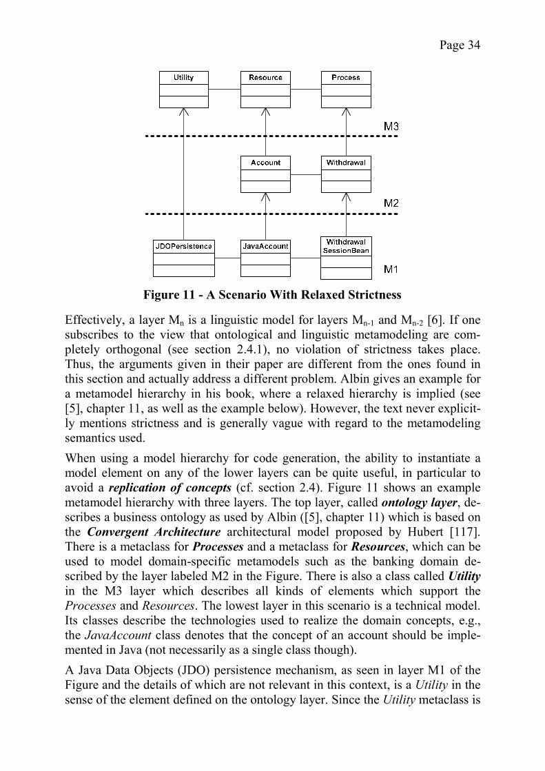
Page 34
Effectively, a layer Mn is a linguistic model for layers Mn-1 and Mn-2 [6]. If one subscribes to the view that ontological and linguistic metamodeling are com-pletely orthogonal (see section 2.4.1), no violation of strictness takes place. Thus, the arguments given in their paper are different from the ones found in this section and actually address a different problem. Albin gives an example for a metamodel hierarchy in his book, where a relaxed hierarchy is implied (see [5], chapter 11, as well as the example below). However, the text never explicit-ly mentions strictness and is generally vague with regard to the metamodeling semantics used. When using a model hierarchy for code generation, the ability to instantiate a model element on any of the lower layers can be quite useful, in particular to avoid a replication of concepts (cf. section 2.4). Figure 11 shows an example metamodel hierarchy with three layers. The top layer, called ontology layer, de-scribes a business ontology as used by Albin ([5], chapter 11) which is based on the Convergent Architecture architectural model proposed by Hubert [117]. There is a metaclass for Processes and a metaclass for Resources, which can be used to model domain-specific metamodels such as the banking domain de-scribed by the layer labeled M2 in the Figure. There is also a class called Utilityin the M3 layer which describes all kinds of elements which support the Processes and Resources. The lowest layer in this scenario is a technical model. Its classes describe the technologies used to realize the domain concepts, e.g., the JavaAccount class denotes that the concept of an account should be imple-mented in Java (not necessarily as a single class though). A Java Data Objects (JDO) persistence mechanism, as seen in layer M1 of the Figure and the details of which are not relevant in this context, is a Utility in the sense of the element defined on the ontology layer. Since the Utility metaclass is
Figure 11 - A Scenario With Relaxed Strictness

Page 35
defined in the M3 layer, it cannot be instantiated on the M1 layer in the case of strict instantiation. One solution is to replicate Utility in the M2 layer (e.g., by having a metaclass called Utility which instantiates M3’s Utility). However, this leads to a replication of concepts which should be avoided for reasons already described. Another alternative is to define a class Persistence in the M2 layer (see Figure 12). At first, this seems to be a good solution (solving the replication issue) but is not really consistent with the interpretation of M2 as a domain-specific layer of the banking domain. The example above leads to two conclusions. First of all, there are scenarios where a relaxed strictness definition can be useful. Second, while there is often a technical way to avoid the need for the relaxation, i.e., by introducing a class in the middle layer(s), this can lead to problems with regard to the semantics of the model layers, especially in the case of domain-specific modeling. Still within the context of the example above, one could argue that the need for a relaxed strictness definition is the result of poor modeling, i.e., that a more suit-able hierarchy would not require such drastic changes to the basic concepts of metamodeling. However, in a metamodel hierarchy, especially one with domain-specific layers, it is sometimes not possible to access all layers for changes, for example, the M3 layer in Figure 11 serves as a basis for all its M2 layers and changes to this metamodel negate many of the advantages described in section 2.1. Having discussed the various advantages and disadvantages of strictness, re-laxed strictness, and the absence of strictness, it is now possible to apply the quality criteria defined in the beginning. Since strictness can lead to a replication of concepts, it can negatively affect both the complexity and consistency of a model hierarchy as explained before. Relaxed strictness on the other hand can
Figure 12 - Introducing a Persistence Metaclass in M2
Page 36
reduce the problem of replication. Nevertheless, some might argue that a relaxed strictness is more complex, as all higher layers have to be considered. Therefore, the degree of perceived complexity may vary. Not using any kind of strictness definition will have a negative impact on the complexity of the model since many of the scenarios presented in Figure 10 are hard to interpret or lead to cir-cular dependencies. A relaxation of strictness has other effects as well, for example it improves the extensibility of a hierarchy. This improvement is caused by the fact that the op-tions for the extension of a specific model layer are not tied to the immediate parent layer but can use any model element in a higher layer as metaelement. As Figure 12 shows, this is not merely a theoretical advantage but one that can be quite useful in the context of ontological hierarchies. The robustness to change of hierarchies with relaxed strictness is difficult to determine. On the one hand, the coupling between the layers is increased and therefore a change in a high layer can possibly affect all lower layers and not just the immediate child. On the other hand, if only the immediate child is changed, it is still possible, and even likely, that the resulting changes in the child will in turn cause changes in its child on so on, effectively causing the same problem. Speaking from personal experience, in most cases a change that affects the direct child will cascade to all of its descendants, regardless of the strictness definition. As a final remark, it should be noted that a relaxed strictness can affect other aspects of a hierarchy. For example, if the concept of potency is used, its defini-tion should probably be relaxed as well to obtain a consistent result (see the next section).
2.4.5 Shallow Versus Deep Instantiation The possibility of choosing different instantiation semantics has already been described in the previous discussion and the decision on depth of instantiation is an important aspect of this choice. This section explains the concepts of shallow and deep instantiation and describes how the other aspects of a metamodel hie-rarchy influence them. A metamodel hierarchy supports deep instantiation if it is possible for a class to make statements about its instances and their instances transitively. If a class can only affect its direct subclass, the system only supports shallow instantiation. The boundaries between the two are not clear-cut. MOF, for example, could be considered to have deep instantiation as the instantiation semantics always de-pends on the metaelement of the element to be instantiated as has been illu-strated in Figure 8 through the arrows. However, it makes more sense to classify MOF as supporting only shallow instantiation because the only factor of influ-ence from the higher layers is the name of the metametaelement which in other words is the type of the direct metaelement. Model elements have no other pos-
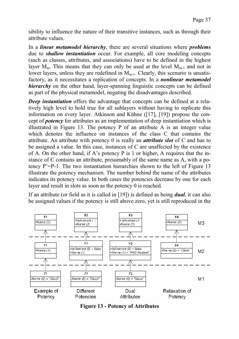
Page 37
sibility to influence the nature of their transitive instances, such as through their attribute values. In a linear metamodel hierarchy, there are several situations where problemsdue to shallow instantiation occur. For example, all core modeling concepts (such as classes, attributes, and associations) have to be defined in the highest layer Mm. This means that they can only be used at the level Mm-1 and not in lower layers, unless they are redefined in Mm-1. Clearly, this scenario is unsatis-factory, as it necessitates a replication of concepts. In a nonlinear metamodel hierarchy on the other hand, layer-spanning linguistic concepts can be defined as part of the physical metamodel, negating the disadvantages described. Deep instantiation offers the advantage that concepts can be defined at a rela-tively high level to hold true for all sublayers without having to replicate this information on every layer. Atkinson and Kühne ([17], [19]) propose the con-cept of potency for attributes as an implementation of deep instantiation which is illustrated in Figure 13. The potency P of an attribute A is an integer value which denotes the influence on instances of the class C that contains the attribute. An attribute with potency 0 is really an attribute slot of C and has to be assigned a value. In this case, instances of C are unaffected by the existence of A. On the other hand, if A’s potency P is 1 or higher, A requires that the in-stance of C contains an attribute, presumably of the same name as A, with a po-tency P’=P-1. The two instantiation hierarchies shown to the left of Figure 13 illustrate the potency mechanism. The number behind the name of the attributes indicates its potency value. In both cases the potencies decrease by one for each layer and result in slots as soon as the potency 0 is reached. If an attribute (or field as it is called in [19]) is defined as being dual, it can also be assigned values if the potency is still above zero, yet is still reproduced in the
Figure 13 - Potency of Attributes

Page 38
lower layers. This can be used to model attributes occurring on several or all model layers such as the name of a model element. The third hierarchy in the Figure shows an example for dual attributes in the form of Name. The simple and elegant potency approach has few disadvantages, the most im-portant of which is the fact that it cannot be easily incorporated into existing me-tamodeling APIs. Also, when using attributes with potency, there is little room for changes to the number of layers. For example in the first hierarchy of Figure 13, it is clear that the Name attribute slot must occur 2 layers below X1. Howev-er, this problem is of only minor importance, as it is always possible to adapt the potencies if a new layer is incorporated. An interesting scenario occurs when combining potency with a relaxation of strictness (see section 2.4.4). The central question in this case is whether poten-cy should be reduced by one for each instantiation or by one for each layer boundary crossed. In any event, a potency value of greater than one imposes a minimum distance on instantiation, e.g., the Z1 instance of X1 could not occur on level M2, because the potency value has to be reduced to 0 first in order to allow the assignment of a value. Using a dual attribute to solve this problem has the disadvantage that some attributes might still have potency even though they are interpreted as slots. For example, in the last hierarchy of Figure 13, a further occurrence of the Name attribute in lower instances might be unwanted but with the normal potency rules would still be possible. A solution to this problem is to introduce a relaxation on potency as well, i.e., allowing the value of the potency to be lowered by 1 or more for each instantiation as is done for X4. Another question to answer when implementing a potency-based hierarchy is whether type, multiplicity, and name of the attribute should be immutably tied to those defined by its topmost definition or not. On the one hand, it might be useful to be able to define types early on, yet on the other hand, some applica-tions might want to leave types open to define them later on. While deep instantiation in the form of potency works reasonably well, it is not necessarily needed for a metamodel hierarchy. It has already been mentioned that nonlinear hierarchies can define many layer-spanning concepts in their physical metamodel. In combination with a relaxed strictness definition, the same modeling power provided by potency is achieved without the need to im-plement a new mechanism. On the other hand, if potency is an existing concept in a modeling language, it is easier to use than this alternative. The final question which arises in the context of deep and shallow instantiation is that of instantiation transitivity. While traditionally instantiation is not consi-dered transitive (e.g., in the MOF standard or in discussions such as [20]), there are also benefits to adopting a pro-transitive view. In particular, ontological me-tamodel hierarchies can profit from transitivity. For example, the hierarchy shown in Figure 7, where instances of Painter are also (transitive) instances of Artist, introduces several levels of abstraction. The transitive form of instantia-
Page 39
tion is preferable to inheritance, another transitive relation, because of the larger amount of control a type has over its instances as opposed to a superclass over its subclasses. Additionally, ontological hierarchies shown in the literature that are not transitive seem to be largely proof-of-concept, thus failing to provide a practical value (e.g., the dog example in [16]). Since transitive instantiation re-fers to layers other than the immediate parent layer, it can be considered an as-pect of deep instantiation. Nevertheless, personal discussion has given me the impression that not every-body considers transitivity a valid option for instantiation, the main argument being that it is the primary factor which distinguishes inheritance from instantia-tion. However, I adopt a different view, considering transitivity an interpretationof a hierarchy and thus part of the realm of semantics that has only peripheral influence on a metamodel, which is a pure syntax definition (see 2.3.2). Since transitive metamodel hierarchies can prove useful for code generation (as illu-strated in chapter 5), it is considered a valid option for metamodel hierarchies. With regard to the quality criteria identified for metamodel hierarchies, the ar-guments in the deep versus shallow instantiation discussion generally seem to be in favor of the former. Deep instantiation is a useful tool to reduce the complexi-ty of a metamodel hierarchy by allowing for the definition of certain fundamen-tal aspects in the higher layers, reducing replication. A single point of definition also helps to improve consistency. Additionally, it also increases the expres-sional strength of the metalayers by giving them the power to influence layers beyond their immediate instance. On the other hand, some people, especially those working mostly with a single layer of the hierarchy, might feel that constructs such as potency increase com-plexity for them. Also, it has been mentioned that unrelaxed potency will limit the maximum number of layers in the hierarchy, thus slightly reducing the ex-tensibility.
2.4.6 Explicit or Implicit Real World Level According to the definition provided in section 2.3.1, models are a representa-tion of systems in the real world. Therefore, a mapping between model elements and elements in the real world exists at least implicitly. In section 2.3.2 the con-cept of semantics was described for this kind of mapping. However, in the light of the confusion surrounding this subject, it is hardly surprising that many dif-ferent views on the problem of real world mapping exist. Opinions on how this mapping should be represented in the context of the model hierarchy vary widely. Atkinson and Kühne claim that in MOF 2.0 and UML 2.0, the real world elements are assumed to reside on the M0 level of the meta-model hierarchy, i.e., they are, in a way, instances of the model elements de-scribing them [16]. However, it is hard to find out on which statements in the standard this claim is based and there is at least one occasion where the standard
Page 40
explicitly contradicts this view (cf. [167], pg. 28). Presumably, an earlier draft version is referenced. Whatever be the case, the benefits of such an explicit real world level are not immediately obvious. A problem of this interpretation is that the metamodel elements have no influence on this mapping if instantiation is shallow (see sec-tion 2.4.5). On the other hand, especially in ontological metamodels, all ele-ments of the same type should be mapped to the same class of real-world ele-ments. Therefore, if a solid definition of the language semantics exists, there is little need for any additional mappings to real world elements. Even more, reducing the concept of semantics to a mapping from elements of the lowest model layer to real-world entities leaves many elements effectively undefined. With regard to the quality criteria, the decision for or against an explicit real world level has little influence. It seems doubtful as to whether the consistency of the hierarchy is improved by an explicit real world layer, whereas the complexity is definitely increased. Since the real world mapping occurs at the single layer, the overall expressional strength of the metalayers remains unchanged. Finally, the exten-sibility and the robustness to change are unaffected as well. Overall, the inclu-sion of a real world level seems to be of little use in most metamodel hierar-chies, even though it is discussed in the literature.
2.4.7 Linguistic Model Element Definitions The linguistic model elements defined for a metamodel hierarchy heavily influ-ence its nature. In a linear hierarchy, these elements are normally defined in the topmost layer and it is prudent to use one of the established standards such as MOF or UML for this layer. A nonlinear framework, on the other hand, gener-ally has to provide more linguistic elements than a linear one. The exact nature of these elements is one of the design choices available during the creation of a metamodel hierarchy infrastructure; a few examples are provided below. Since the linguistic metamodel of MOF has already been described in detail, it is omit-ted from the discussion below. Also, the discussion is limited to class diagrams, even though the design space is suitable for any kind of metamodel hierarchy (see section 5.1.2). A naïve approach for nonlinear cases (as described and criticized by Atkinson and Kühne [17]) is to have one class for each layer. The drawback of this ap-proach is that the number of layers will be fixed by the number of model ele-ments defined. For example, if the model elements metametaclass, metaclass, class, and object were defined, the number of layers would be limited to 4. Clearly, this is a poor solution which would also be quite confusing in more complex cases with many layers. On the other end of the scale is a solution offered by Atkinson and Kühne that has but a single element called modelelement, which contains a level attribute
Page 41
that identifies the level the element is found on, effectively making it a class, object, or metaclass [17]. A problematic aspect of this approach is the mixing of different concepts in a single element, making it more difficult to use. A third variant, again proposed by Atkinson, can be found somewhere in the middle between the two other propositions. It consists of the model elements (meta)class, clabject, and object. A (meta)class is a type for an object or a clab-ject and has no type itself. A clabject on the other hand is both an instance and a type, combining the properties of both object and (meta)class. Thus it has links as well as associations, attributes and attribute slots [21]. A model hierarchy based on these elements would have a clear top level and clear termination at the bottom. It is interesting to note that this structure implies an axiomatic top level (see section 2.4.8). While this solution remedies the problem of the previous ap-proach, the clabject concept feels like an artificial construct, at the very least due to its name. Another solution, proposed in chapter 5, is a form of compromise between the single model and the clabject approach. There are three main elements, class, metaclass, and model layer, ignoring any classes representing associations for the moment. Instead of identifying an element’s layer by an attribute value, the element is associated with a model layer by containment. This approach has the advantage that it allows the relatively easy introduction of new model layers at the bottom or in between, without having to change the value of the layer attribute in many or even all elements. Also, it allows for the inclusion of infor-mation about a layer which affects all its elements and can be used to check compliance to domain-specific constraints. Effectively, a metaclass has all the properties of a clabject and a metaclass as proposed above. This simplification reduces the number of model elements but in my opinion does not reduce the power or quality of the model. Note that the inclusion of an object class is also possible, but adds little to the power of the modeling hierarchy, especially when using the models in an MDD context. A further question is whether to include methods or operations in the model hie-rarchy or not. While UML makes extensive use of methods, they are less useful in higher model layers or when no direct one-to-one mapping to code is in-tended. Atkinson shares this view, claiming that “[i]n practice the operations and methods are unimportant for meta-modeling purposes” ([21], pg. 97). Yet, Geis-ler et al. criticize this view, pointing out the contribution of methods to the “de-scription of system dynamics and evolution” ([81], pg. 18). One possibility is to have methods at the metalevels to support the enforcement of constraints, for example by providing derived information via methods such as allSupertypes()found in GeneralizableElement of MOF. With arguments existing for both opi-nions, the decision whether to include methods or not is largely situation-dependent.
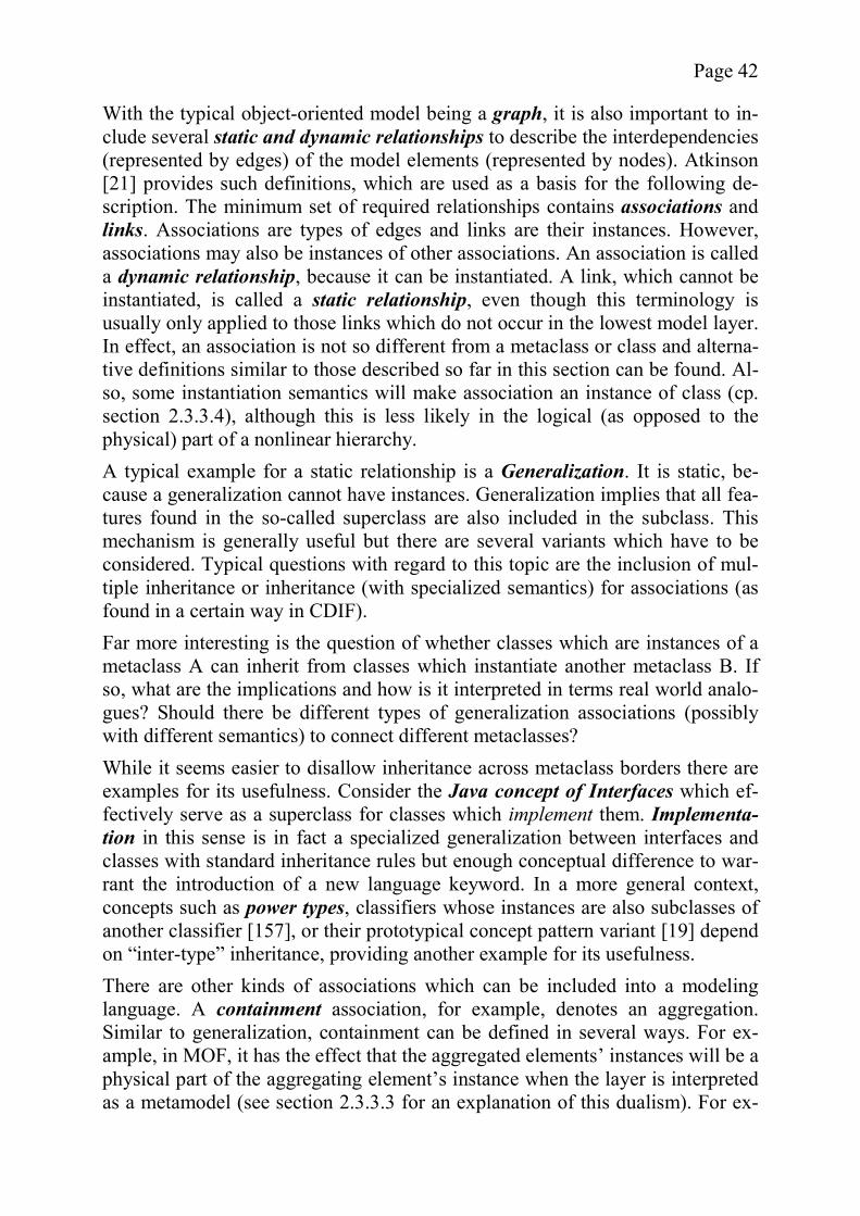
Page 42
With the typical object-oriented model being a graph, it is also important to in-clude several static and dynamic relationships to describe the interdependencies (represented by edges) of the model elements (represented by nodes). Atkinson [21] provides such definitions, which are used as a basis for the following de-scription. The minimum set of required relationships contains associations andlinks. Associations are types of edges and links are their instances. However, associations may also be instances of other associations. An association is called a dynamic relationship, because it can be instantiated. A link, which cannot be instantiated, is called a static relationship, even though this terminology is usually only applied to those links which do not occur in the lowest model layer. In effect, an association is not so different from a metaclass or class and alterna-tive definitions similar to those described so far in this section can be found. Al-so, some instantiation semantics will make association an instance of class (cp. section 2.3.3.4), although this is less likely in the logical (as opposed to the physical) part of a nonlinear hierarchy. A typical example for a static relationship is a Generalization. It is static, be-cause a generalization cannot have instances. Generalization implies that all fea-tures found in the so-called superclass are also included in the subclass. This mechanism is generally useful but there are several variants which have to be considered. Typical questions with regard to this topic are the inclusion of mul-tiple inheritance or inheritance (with specialized semantics) for associations (as found in a certain way in CDIF). Far more interesting is the question of whether classes which are instances of a metaclass A can inherit from classes which instantiate another metaclass B. If so, what are the implications and how is it interpreted in terms real world analo-gues? Should there be different types of generalization associations (possibly with different semantics) to connect different metaclasses? While it seems easier to disallow inheritance across metaclass borders there are examples for its usefulness. Consider the Java concept of Interfaces which ef-fectively serve as a superclass for classes which implement them. Implementa-tion in this sense is in fact a specialized generalization between interfaces and classes with standard inheritance rules but enough conceptual difference to war-rant the introduction of a new language keyword. In a more general context, concepts such as power types, classifiers whose instances are also subclasses of another classifier [157], or their prototypical concept pattern variant [19] depend on “inter-type” inheritance, providing another example for its usefulness. There are other kinds of associations which can be included into a modeling language. A containment association, for example, denotes an aggregation. Similar to generalization, containment can be defined in several ways. For ex-ample, in MOF, it has the effect that the aggregated elements’ instances will be a physical part of the aggregating element’s instance when the layer is interpreted as a metamodel (see section 2.3.3.3 for an explanation of this dualism). For ex-

Page 43
ample, Attribute model elements contained by a Class are not seen as individual elements but rather as attributes of the class. Having described just a few of the endless options available in this context, it is difficult to make a general statement about the impact of the choice of model elements on the quality criteria. The complexity is influenced by the number of linguistic elements as well as by their design. For example, adding methods will increase the complexity of a hierarchy. However, in general, the addition of carefully chosen new model elements will reduce the complexity. This is the case with the addition of a generalization link, which helps avoid the need to define attributes redundantly. Also, a limited number of elements might reduce the expressional strength of the metalayers since many instances will have the same metaclass. Therefore, the choice of metaclass does not convey a lot of information about the instance. For example, when trying to provide a simplified look at the hierarchy by using the metaelements, a lot of information will be lost. The consistency of a hierarchy is also strongly influenced by the choice of its linguistic model elements. For example, overlapping responsibilities should be avoided since they easily lead to inconsistencies. Generally speaking, the most expensive changes to a metamodel hierarchy are those made to its linguistic elements, since they mostly reside in the higher lay-ers of the hierarchy or, in the case of some nonlinear hierarchies, they directly affect all ontological layers. If linguistic metaelements are identified which can cover a wide range of ontological instances, changes to the ontological model layers are unlikely to require a change at the linguistic level which implies a cer-tain robustness to change. Similarly, an intelligent choice of elements positively influences the extensibility. Due to the fact that the choice of linguistic model elements has a great impact on the quality criteria, it is of vital importance and requires careful planning. On the other hand, no general rule of thumb can be provided and applied to all cases.
2.4.8 Axiomatic Versus Recursive Top Level In a strict metamodel hierarchy all elements in a layer Mn are defined by the me-taelements in Mn+1, the obvious exception being the top-most layer. The top-most layer can take two forms. It can be a recursively defined layer or an axi-omatic layer. MOF is an example for a recursive top level, as is CDIF. Riehle et al. [176] give an example for a logical metamodel which is recursive at the top. On the other hand, some researchers, such as Seidewitz [186] or Geisler et al. [81], are opposed to the recursive top level concept. In the case of a recursive top level metamodel, the metamodel is self-describing. Figure 14 shows an example taken from the MOF metamodel, reduced to the Class, Association, and AssociationEnd elements. For reasons of clarity, the
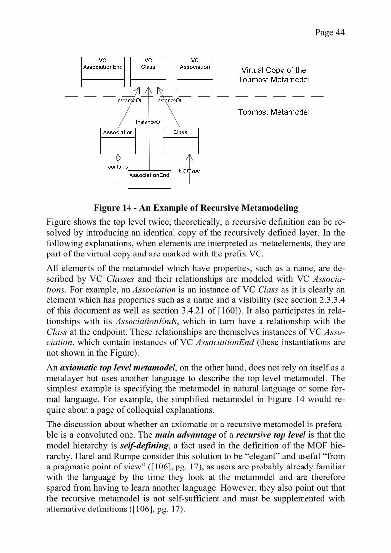
Page 44
Figure shows the top level twice; theoretically, a recursive definition can be re-solved by introducing an identical copy of the recursively defined layer. In the following explanations, when elements are interpreted as metaelements, they are part of the virtual copy and are marked with the prefix VC. All elements of the metamodel which have properties, such as a name, are de-scribed by VC Classes and their relationships are modeled with VC Associa-tions. For example, an Association is an instance of VC Class as it is clearly an element which has properties such as a name and a visibility (see section 2.3.3.4 of this document as well as section 3.4.21 of [160]). It also participates in rela-tionships with its AssociationEnds, which in turn have a relationship with the Class at the endpoint. These relationships are themselves instances of VC Asso-ciation, which contain instances of VC AssociationEnd (these instantiations are not shown in the Figure). An axiomatic top level metamodel, on the other hand, does not rely on itself as a metalayer but uses another language to describe the top level metamodel. The simplest example is specifying the metamodel in natural language or some for-mal language. For example, the simplified metamodel in Figure 14 would re-quire about a page of colloquial explanations. The discussion about whether an axiomatic or a recursive metamodel is prefera-ble is a convoluted one. The main advantage of a recursive top level is that the model hierarchy is self-defining, a fact used in the definition of the MOF hie-rarchy. Harel and Rumpe consider this solution to be “elegant” and useful “from a pragmatic point of view” ([106], pg. 17), as users are probably already familiar with the language by the time they look at the metamodel and are therefore spared from having to learn another language. However, they also point out that the recursive metamodel is not self-sufficient and must be supplemented with alternative definitions ([106], pg. 17).
Figure 14 - An Example of Recursive Metamodeling
Page 45
The potential problems of a recursive top level described in the literature are somewhat hard to grasp. For instance, according to Atkinson, it is difficult to understand a definition with information “coming from thin air” [21]. While re-cursive definitions also exist in areas such as mathematics and are not consi-dered problematic in that context, the situation is different with metamodels. While a mathematical definition has a recursion base which breaks the infinite loop, there is no such thing in the context of recursive language definitions. Thus a recursive definition is not self-sufficient (cf. [106], pg. 17) but needs to be supported by some other form of definition at least for a subset of its ele-ments. As mentioned above, Seidewitz also criticizes recursive (or in his terms “reflex-ive”) metamodels. As has been shown in Figure 14, the recursion can be re-solved by duplicating the metamodel. These duplicate metamodels actually need less different types of model elements (i.e., only a subset is required for the self-specification), but still become increasingly complex with regard to the number of instances. For example, an Association in MOF, when seen as an instance of the MOF metamodel, consists of three objects and several relationships. All these instances have to correspond to the metamodel. Repeating this step for the metamodel again in order to check its validity in turn leads to increasingly com-plex models if done repetitively (cf. [186], [187]). However, the purpose of re-solving the recursion in such a way is left unclear. Therefore, this argument is only considered to be of minor importance in this context. The concept of an axiomatic top level definition, on the other hand, is far easier to grasp than a recursive one. Geisler et al. for example propose the use of a formal metalanguage to avoid “self-referencing problems” ([81], pg. 5). Note that in the context of nonlinear metamodel hierarchies (see section 2.4.1) the highest ontological layer can easily be seen as axiomatic with the linguistic me-tamodel taking the part of the metalanguage. However, axiomatic top level defi-nitions are criticized as well and suffer from a few drawbacks that are not shared by the recursive version. Atkinson [21] finds an axiomatic top level problematic because its top level elements cannot be treated as objects, however gives no example when such an interpretation would be useful. Albin even indirectly ne-gates the possible existence of axiomatic metamodels by saying that “every model has a metamodel that describes it, although the metamodel may be impli-cit” ([5], chapter 11). Since many metalanguages, such as natural language, are also recursively defined, it might seem questionable to some, why they should be preferable to a recursive top level model. On the other hand, for the purposes of most applications the natural language part can be safely ignored and be seen as a purely philosophical issue. The decision between an axiomatic and recursive definition has some influence on the quality of a hierarchy but based on the various statements made in this context, it will be hard to come up with an evaluation which gives equal recog-nition to all the opinions described above. For example while some see a recur-
Page 46
sive definition as a tool for reducing complexity, others feel exactly the opposite way. If a recursive definition can really be considered self-sufficient, the former opinion is probably correct. On the other hand, when designing a new recursive top level, there is a great danger of introducing mistakes, i.e., the task of creating the hierarchy is very complex. The same arguments can be applied to the consistency of a model. If self-sufficient, a recursive definition avoids the need of a replicated metamodel defi-nition in another language and thus reduces the risk of inconsistencies. The criteria of extensibility and expressional strength of the metalayers are largely unaffected by the decision with regard to the topmost layer. However, some might argue that by resolving the recursion, additional layers can be added to the hierarchy, which can then be extended with additional metaelements. Whether this reasoning is correct or not, the most prominent real world exam-ples tend to have a recursive top level. In my opinion, in a linear hierarchy, a recursive metamodel, augmented with natural language clarifications, is prefera-ble to a purely axiomatic approach. However, it is even better to have a recur-sive metamodel and its explanations offered as an alternative to an existing for-mal definition, as is proposed by Harel and Rumpe [106]. In a nonlinear hie-rarchy, the highest ontological layer can be considered axiomatic as it is defined in terms of the linguistic metamodel which are beyond the scope of the ontolog-ical aspects. In this case, the addition of a recursion in the logical part only adds additional complexity as the linguistic metamodel already exists.
2.4.9 Evaluation of a Metamodel Hierarchy Given the countless number of choices described above, it is hard to form a solid opinion on what constitutes a good metamodel hierarchy with regard to the goals of general applicability and ease of use at all levels of abstraction. Even with the criteria of complexity, consistency, expressional strength, extensibility, and ro-bustness to change, this decision is difficult, especially since the emphasis be-tween these criteria can vary for individual projects. Still, tendencies can be identified, especially when looking at those design op-tions which are limited to a finite number of choices or whose possible values can at least be grouped into categories. Table 1 shows the tangible design op-tions for metamodel hierarchies in an overview, assigning each of the possible choices a rating where applicable. With the help of the Table, several conclusions can be drawn. First of all, the real world level discussion seems to be largely pointless, at least in the light of the defined criteria and thus, an explicit real-world level is not worth the effort. The discussion regarding whether an axiomatic or recursive top level model is the better choice, on the other hand, cannot be solved, because the interpretation of its impact depends largely on one’s standpoint. Thus, no recommendation can be given.
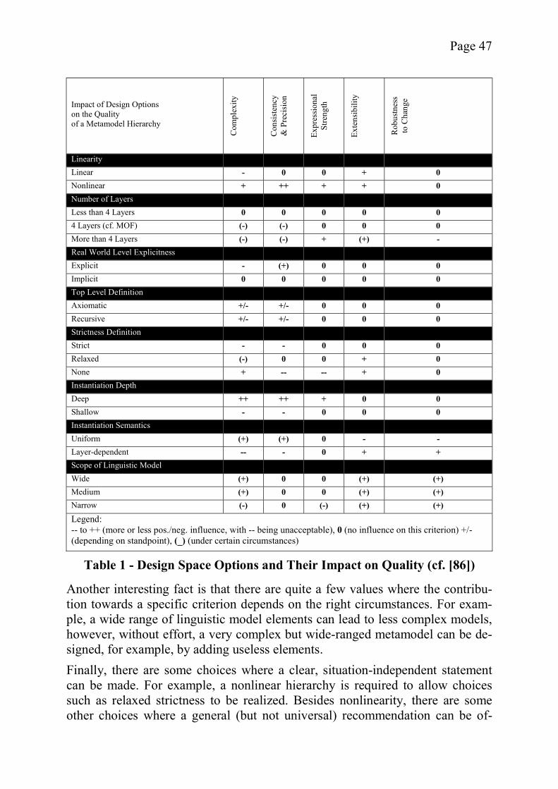
Page 47
Another interesting fact is that there are quite a few values where the contribu-tion towards a specific criterion depends on the right circumstances. For exam-ple, a wide range of linguistic model elements can lead to less complex models, however, without effort, a very complex but wide-ranged metamodel can be de-signed, for example, by adding useless elements. Finally, there are some choices where a clear, situation-independent statement can be made. For example, a nonlinear hierarchy is required to allow choices such as relaxed strictness to be realized. Besides nonlinearity, there are some other choices where a general (but not universal) recommendation can be of-
Impact of Design Options on the Quality of a Metamodel Hierarchy
Com
plex
ity
Con
sist
ency
&
Pre
cisi
on
Expr
essi
onal
St
reng
th
Exte
nsib
ility
Rob
ustn
ess
to C
hang
e
Linearity Linear - 0 0 + 0 Nonlinear + ++ + + 0 Number of Layers Less than 4 Layers 0 0 0 0 0 4 Layers (cf. MOF) (-) (-) 0 0 0 More than 4 Layers (-) (-) + (+) - Real World Level Explicitness Explicit - (+) 0 0 0 Implicit 0 0 0 0 0 Top Level Definition Axiomatic +/- +/- 0 0 0 Recursive +/- +/- 0 0 0 Strictness Definition Strict - - 0 0 0 Relaxed (-) 0 0 + 0 None + -- -- + 0 Instantiation Depth Deep ++ ++ + 0 0 Shallow - - 0 0 0 Instantiation Semantics Uniform (+) (+) 0 - - Layer-dependent -- - 0 + + Scope of Linguistic Model Wide (+) 0 0 (+) (+) Medium (+) 0 0 (+) (+) Narrow (-) 0 (-) (+) (+) Legend: -- to ++ (more or less pos./neg. influence, with -- being unacceptable), 0 (no influence on this criterion) +/- (depending on standpoint), (_) (under certain circumstances)
Table 1 - Design Space Options and Their Impact on Quality (cf. [86])
Page 48
fered. For instance, relaxed strictness is a preferable choice when possible, avoiding many of the problems caused by traditional strictness. Also, the lin-guistic model, if carefully designed, can provide a number of improvements in nearly all categories. On the other hand, a layer-dependent instantiation seman-tics should be avoided at all costs, increasing the complexity to an unacceptable degree, unless there are only a few layers.
2.5 Conclusion In this section, a robust set of definitions has been created from a selection of conflicting opinions on the subject matter. Using these definitions, the principles of metamodeling have been explained with examples based on the MOF stan-dard. Also, options available to the designer of a metamodel hierarchy have been analyzed and evaluated by applying several quality criteria derived from the goal of creating a highly reusable and easy-to-use hierarchy. Based on the defi-nitions and the design options for metamodels, the benefits of metamodeling for Model-Driven Development can be explained in detail in the next chapter.
Page 49
3 Model-Driven Development According to Denning, the misconception that “Computer Science equals pro-gramming” is a major problem which led to the software crisis in the sixties. It causes problems even today as it leads to a neglect of other important aspects such as the engineering of systems and modeling [56]. Bézivin even goes so far as to talk of a second software crisis due to increasing complexity caused among other things by massive technological heterogeneity ([30], pg. 7). Model-driven development (MDD) approaches aim at putting the model at the center of atten-tion, making it the most important artifact for the whole software lifecycle. With the help of code generators applied to these models, software engineering takes a step away from programming. The focus on models is meant to increase the level of abstraction involved in the creation and alteration of software and to re-duce a product’s vulnerability to change during its whole lifecycle. Its suppor-ters see it as a next step in the evolution of software development akin to the in-troduction of compilers (e.g., [141], chapter 1, pg. 3), and its opponents as big hype with little substance, that will basically amount to a recycling of ideas that have already failed in the past. A derisive term often quoted in this context is “cocktail party myth” (e.g., [100]). In order to provide a foundation for reasoning, both for and against the concepts of MDD, its goals and fundamentals will be briefly described, at first without differentiating between realistic visions and marketing hype. This abstract over-view will be illustrated by describing the state of the art and further examining the OMG’s MDA concept and the Executable UML approach. After that, the advantages and disadvantages as described by various authors will be discussed. It will be shown that domain-specific approaches are a solution to MDD’s short-comings and the role metamodeling can play in realizing such approaches will be described.
3.1 Goals and Aspired Benefits of MDD While there are many different interpretations of what the benefits of MDD are or will be, it is possible to identify two central goals which are often cited. One of these goals, in the words of Atkinson and Kühne, is to “reduce [the primary software artifacts’] sensitivity to the inevitable changes that affect a software system” [18]. This quotation forms a roof for a catalogue of sub-goals and bene-fits resulting from the aspired robustness. The second goal, identified by authors such as Mellor and Balcer [139], Bézivin [30], Selic [190], or Booch et al. [34], is an increase of abstraction, allowing to better deal with the problem of com-plexity. While it would be going too far to see change and complexity as the on-ly difficulties in software engineering, they can be considered two of its core problems (cf. [102], [38]). Thus, any approach addressing these two problems will ultimately result in a reduction of cost, which is the main selling argument
Page 50
given by MDD proponents [141]. However, the cost reduction depends on whether the model-driven concept lives up to its stated goals.
3.1.1 Resistance to Change According to Greenfield et al., software development is the process of imple-menting a mapping between a problem and a solution domain, with the final software product being an element of the latter ([102], pp. 90). Based on this abstract point of view, it becomes obvious that there are two areas of change which must both be considered. Besides the expected changes to the solution domain (e.g. the addition of new solutions due to new technological platforms), changes can also occur in the problem domain (e.g., the addition of new busi-ness processes) ([102], pp. 99). In order to achieve resistance to change, both types must be considered. Greenfield et al. identify several software aging problems which are caused by multiple modifications in a software system. These problems can manifest re-gardless of whether the change occurred in the problem or the solution domain. The first one, called stagnation, increases with the amount of required changes which have been deferred to the future. A high level of stagnation can eventually render the required changes impossible. Fatigue covers all problems caused by suboptimal changes to the software, e.g. due to the addition of new features which the original architecture did not foresee and is unable to appropriately support. Brittleness is a measure of how well software can take additional changes and is likely to increase over time unless countermeasures are taken. Finally, redundancy describes the level of data and code duplication in a system or the whole organization ([102], pp. 88). While other views on the subject are possible as well, the above analysis of the problem of change is a good basis for describing how MDD can potentially ad-dress its challenges. According to its proponents, the MDD approach introduces resistance to change in several ways, as described below. Many discussions of MDD focus on changes in the solution domain, seeing the technological platform as a prime source of change. By focusing on a model which is in synch with the software artifacts at all times, MDD supporters hope to achieve a separation of business requirements and technology ([109], [141]) and therefore a platform independence of sorts ([189], [141]). Platform in-dependence implies the ability to quickly react to changing technological back-grounds ([189], [207]), provides improved portability ([53], [141], [139], pg. 11), and supports interoperability ([141], pg. 1-2). However, the ability to react to changes in the problem domain is also im-proved by keeping the model as the central artifact during all stages of a soft-ware project’s lifecycle. Such a model not only greatly aids the understanding of the system but can also be used to quickly implement business level updates, thus providing the potential for improved maintainability [53] [136]. Mainten-
Page 51
ance, which is not limited to error correction but rather focuses on the addition of new business level features, is an important factor in software engineering that is neglected by many approaches (cf. Glass [94]). Support for alterations to the software at any time of the lifecycle is a major advantage of using model-centric approaches. Also, the in-synch model could be useful for other neglected tasks such as project retrospectives to avoid what Glass calls “making the same mistakes on project after project” [98]. For Haywood the proper emphasis on modeling and design seems to be the most important benefit of model-centricity, in fact he doubts that the resistance to change will be as great as gen-erally assumed by most MDD advocates [109]. The expected advantages of MDD increase the resistance to change, because they better address most of the software aging problems described above as op-posed to the general state of the practice (cf. [102], pp. 101). First of all, the eas-ier maintenance becomes, the less danger exists that stagnation will occur. Brit-tleness is currently reduced by the use of encapsulation and adaptive design (i.e., anticipating changes and providing a modular structure which allows easy re-placement of components). Reduced to its smallest common denominator, MDD offers no special potential here. On the other hand, fatigue can be avoided, as it is now easier to refactor systems based on the model which reflects the system’s architecture rather than its implementation details. Finally, data redundancy at an organizational level can be reduced due to MDD’s contribution to interopera-bility. In summary, MDD as a concept addresses many but not all of the problems as-sociated with change (as shown in Table 2). Thus, if MDD lives up to its poten-tial and if software really is prone to the types of change described here, MDD represents an improvement over the current state of software engineering. The arguments found in this context will be discussed in section 3.3.
3.1.2 Increased Level of Abstraction As has already been mentioned, many researchers, such as Mellor and Balcer, see a higher level of abstraction as the main goal of MDD, which addresses the problem of complexity. Again, it seems prudent to come up with a definition of the problem first and then describe how MDD intends to address its aspects.
Page 52
Complexity can be defined as a “measure of the difficulty of solving a given problem” ([102], pg. 35). According to Brooks, it can be divided into essential and accidental complexity. Accidental complexity describes complications which are not part of the actual problem, e.g., difficulties which can be ignored when raising the level of abstraction without significantly changing the behavior of the system. Essential complexity, on the other hand, covers those aspects which cannot be ignored safely as part of an abstraction, the essential parts of the problem, as the name implies [38] . Thus, only the accidental complexity can be reduced by increasing the level of abstraction. While Greenfield et al. see a lot of accidental complexity in modern systems such as the Java 2 Enterprise Edition (J2EE) [191] (cf. [102], pg. 36), Brooks sees it as a minor aspect and fears that too much abstraction will lead to “a tool-mastery burden that increases, not reduces, the intellectual task of the user who rarely uses the esoteric constructs” [38]. Greenfield et al. identify feature delocalization as a typical accidental complexi-ty factor. Feature delocalization occurs if an object in the problem domain is addressed by several objects in the solution domain, often due to technical re-quirements regarding persistence etc. The delocalization makes it difficult to find out which solution elements correspond to which problem elements, leading to a traceability problem (cf. [102], pp. 36). Feature delocalization is the focus of attention of aspect-oriented programming (cf. [102], pp. 71). In order to overcome the problem of accidental complexity as described, Mellor and Balcer hope to achieve a higher level of abstraction by using an executable variant of UML (see section 3.2.2.3). The increase in abstraction is an advantage of MDD also cited by Booch et al. [34], Kühne [136], Selic [190], and Muller et al. [142]. Cook and Booch et al. see the introduction of domain-specific lan-
Problem Theoretical MDD Contribution (from None to ++)
Problem Domain Change +
Solution Domain Change ++
Stagnation ++
Fatigue ++
Brittleness None
Redundancy +
Table 2 - Potential Benefits of MDD for the Resistance to Change

Page 53
guages, as opposed to technology-oriented conglomerates of different pro-gramming languages, as the main reason for this new level of abstraction ([51], [34]). Since the abstraction from programming-level issues makes the integra-tion of domain experts easier (see Völter [209]), possibly by providing several different views on the same system (cf. Kent [131]), MDD might be considered related to or maybe even a subcategory of the field of End-User Development (see Stutcliffe and Mehandjiev [203]), another well-known approach to reducing complexity. The technical foundation, allowing the increased level of abstraction, consists of code generators of various types which convert business models into platform-specific code ([109], [139], and [141]). The reduction in complexity caused by the use of code generation is expected to lead to improved software quality([53], [109], [136], [34], [209]). It can also result in high reusability ([136], [189]) and therefore increased productivity ([53], [109], and [209]) as well as rapid development ([109], [34]), by deferring many of the less intellectually challenging aspects of programming to the code generator [34]. Some MDD-proponents see great potential in aspect oriented programming, believing that the introduction of aspects is possible and will help to reach the goals of MDD ([30], [109], [136], [139], pg. 39, [209]). While it is never men-tioned in these terms, the problem of feature dislocation can thus be solved with-in the context of MDD. Complexity is a somewhat intangible term, making it hard to assess solutions to this problem. The general opinion among its supporters seems to be that MDD has a lot to offer in this context, providing a wide range of advantages related to this subject. However, as we will see below, this view depends a lot on how much of software’s complexity is accidental and how much is essential.
3.2 MDD Origins and State of the Art Whether proposed under the name Model-Driven Development, Model-Driven Software Development (MDSD) [209], Model-Driven Engineering (MDE) [30], or mistakenly under the trademarked label Model Driven Architecture[141] (cf. Cook [51]), the model-driven approach is considered to herald a new era of software development. Just as the advent of compilers introduced a new abstraction layer on top of the machine code layer in use at that time, the goal of MDD approaches is to achieve further simplification by using design models and code generators ([189], [207]). Jacobson, one of the architects of UML, is convinced that Executable UML models will be possible, first for “a small ste-reotypical class of systems” and in the long run for “the majority of software development” ([139], pg. xxiv).
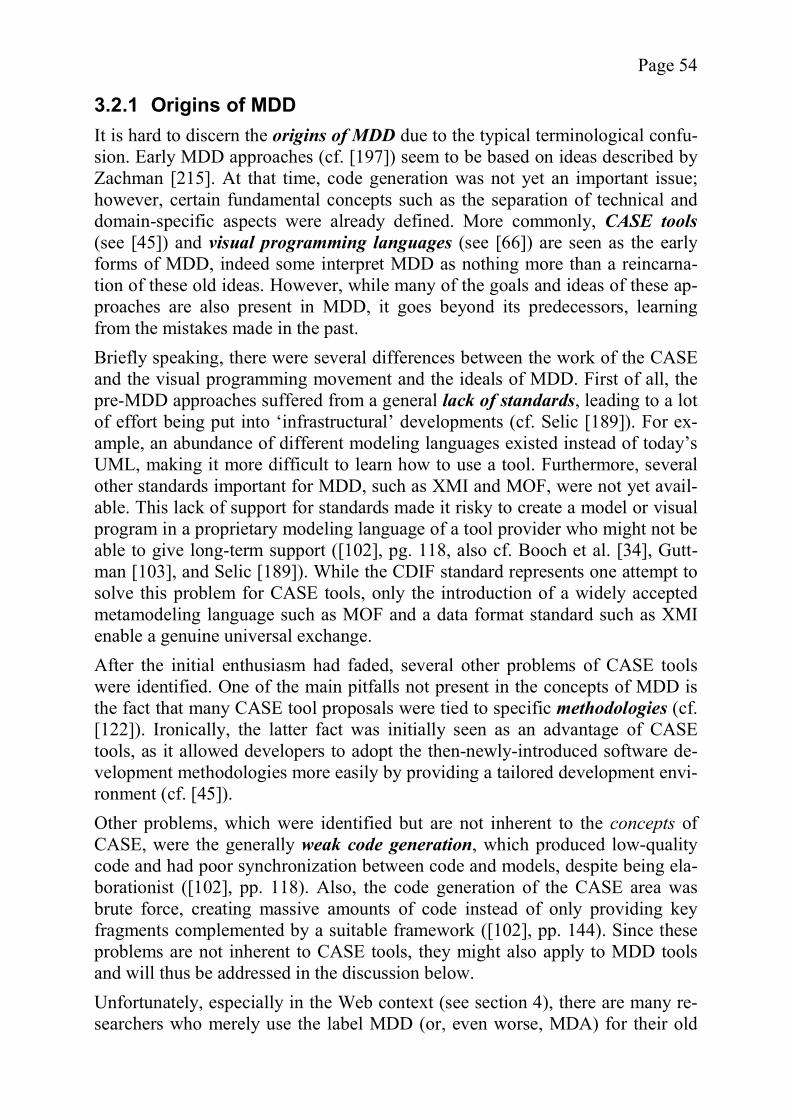
Page 54
3.2.1 Origins of MDD It is hard to discern the origins of MDD due to the typical terminological confu-sion. Early MDD approaches (cf. [197]) seem to be based on ideas described by Zachman [215]. At that time, code generation was not yet an important issue; however, certain fundamental concepts such as the separation of technical and domain-specific aspects were already defined. More commonly, CASE tools(see [45]) and visual programming languages (see [66]) are seen as the early forms of MDD, indeed some interpret MDD as nothing more than a reincarna-tion of these old ideas. However, while many of the goals and ideas of these ap-proaches are also present in MDD, it goes beyond its predecessors, learning from the mistakes made in the past. Briefly speaking, there were several differences between the work of the CASE and the visual programming movement and the ideals of MDD. First of all, the pre-MDD approaches suffered from a general lack of standards, leading to a lot of effort being put into ‘infrastructural’ developments (cf. Selic [189]). For ex-ample, an abundance of different modeling languages existed instead of today’s UML, making it more difficult to learn how to use a tool. Furthermore, several other standards important for MDD, such as XMI and MOF, were not yet avail-able. This lack of support for standards made it risky to create a model or visual program in a proprietary modeling language of a tool provider who might not be able to give long-term support ([102], pg. 118, also cf. Booch et al. [34], Gutt-man [103], and Selic [189]). While the CDIF standard represents one attempt to solve this problem for CASE tools, only the introduction of a widely accepted metamodeling language such as MOF and a data format standard such as XMI enable a genuine universal exchange. After the initial enthusiasm had faded, several other problems of CASE tools were identified. One of the main pitfalls not present in the concepts of MDD is the fact that many CASE tool proposals were tied to specific methodologies (cf. [122]). Ironically, the latter fact was initially seen as an advantage of CASE tools, as it allowed developers to adopt the then-newly-introduced software de-velopment methodologies more easily by providing a tailored development envi-ronment (cf. [45]). Other problems, which were identified but are not inherent to the concepts of CASE, were the generally weak code generation, which produced low-quality code and had poor synchronization between code and models, despite being ela-borationist ([102], pp. 118). Also, the code generation of the CASE area was brute force, creating massive amounts of code instead of only providing key fragments complemented by a suitable framework ([102], pp. 144). Since these problems are not inherent to CASE tools, they might also apply to MDD tools and will thus be addressed in the discussion below. Unfortunately, especially in the Web context (see section 4), there are many re-searchers who merely use the label MDD (or, even worse, MDA) for their old
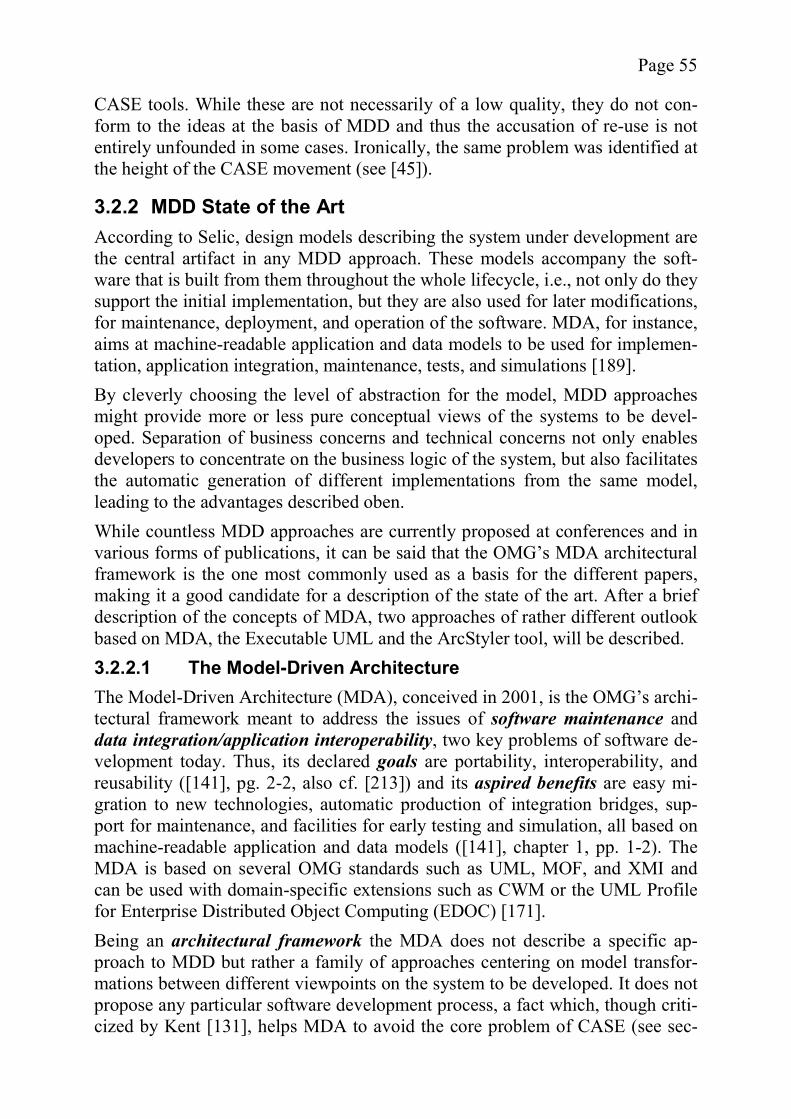
Page 55
CASE tools. While these are not necessarily of a low quality, they do not con-form to the ideas at the basis of MDD and thus the accusation of re-use is not entirely unfounded in some cases. Ironically, the same problem was identified at the height of the CASE movement (see [45]).
3.2.2 MDD State of the Art According to Selic, design models describing the system under development are the central artifact in any MDD approach. These models accompany the soft-ware that is built from them throughout the whole lifecycle, i.e., not only do they support the initial implementation, but they are also used for later modifications, for maintenance, deployment, and operation of the software. MDA, for instance, aims at machine-readable application and data models to be used for implemen-tation, application integration, maintenance, tests, and simulations [189]. By cleverly choosing the level of abstraction for the model, MDD approaches might provide more or less pure conceptual views of the systems to be devel-oped. Separation of business concerns and technical concerns not only enables developers to concentrate on the business logic of the system, but also facilitates the automatic generation of different implementations from the same model, leading to the advantages described oben. While countless MDD approaches are currently proposed at conferences and in various forms of publications, it can be said that the OMG’s MDA architectural framework is the one most commonly used as a basis for the different papers, making it a good candidate for a description of the state of the art. After a brief description of the concepts of MDA, two approaches of rather different outlook based on MDA, the Executable UML and the ArcStyler tool, will be described. 3.2.2.1 The Model-Driven Architecture The Model-Driven Architecture (MDA), conceived in 2001, is the OMG’s archi-tectural framework meant to address the issues of software maintenance and data integration/application interoperability, two key problems of software de-velopment today. Thus, its declared goals are portability, interoperability, and reusability ([141], pg. 2-2, also cf. [213]) and its aspired benefits are easy mi-gration to new technologies, automatic production of integration bridges, sup-port for maintenance, and facilities for early testing and simulation, all based on machine-readable application and data models ([141], chapter 1, pp. 1-2). The MDA is based on several OMG standards such as UML, MOF, and XMI and can be used with domain-specific extensions such as CWM or the UML Profile for Enterprise Distributed Object Computing (EDOC) [171]. Being an architectural framework the MDA does not describe a specific ap-proach to MDD but rather a family of approaches centering on model transfor-mations between different viewpoints on the system to be developed. It does not propose any particular software development process, a fact which, though criti-cized by Kent [131], helps MDA to avoid the core problem of CASE (see sec-
Page 56
tion 3.2.1). Kleppe et al. provide a short list of possible processes and their sui-tability for MDA ([133], pp. 40-42). Typically the designers start with the creation of a Computation-Independent Model (CIM), a domain model which describes the problem independently from the implementation in the vocabulary of the domain’s practitioners. This model serves as an informal basis for the design of the Platform-Independent Model (PIM). The PIM is a technology-neutral description of the system, ideally de-scribed as a program for a generic virtual machine. This neutral model, when combined with a Platform Model, i.e., a description of the technical concepts and services of a specific platform, can be transformed into the corresponding Platform-Specific Model (PSM). The PSM in turn may be used as the starting point for subsequent transformations which eventually lead to the generation of source code. The output of a transformation can also include a record of trans-formation which can be used to synchronize the PIM and PSM in the case of changes in either model ([141], chapter 2). The MDA is somewhat open in its definitions and in fact offers several alterna-tives for the nature of the models and the transformations. In the most advanced scenario, the PIM is semantically rich enough to not require additional annota-tions and can be transformed to code directly. The PSM can still be generated, of course, but mostly serves debugging purposes. On the other end of the scale are transformation approaches where the model elements in the input model are marked with annotations, for example UML stereotypes, which allow mapping rules for the automatic (or manual!) generation of the output model ([141], chap-ters 3 and 4). A single input model may also be submitted to several different transformations, e.g., generating the application in variants for different platforms. In a more in-volved scenario, different components of the system are generated for different platforms and bridges are automatically provided as part of the transformation ([141], chapter 5). While the MDA has raised the interest in MDD approaches and offers several intriguing ideas, it is generally too theoretical and abstract to assess its feasibili-ty. These problems along with the intentionally high degree of freedom for its instances have led to a wide range of different implementations. According to Haywood, MDA-based approaches can be separated into two distinct, even competing, branches he calls the elaborationists and the translationists. In an elaborationist approach, the static aspects of an application are described by PIMs. Additional information is then added by annotating the PIMs to create PSMs. However, the behavior of the modeled system is mainly described by code added to the generated files, limiting code generation to about 50-60%. ArcStyler, a tool by IO-Software falls into this category [119]. Translationists, on the other hand, aim at 100% code generation, specifying behavior by using statecharts and an action language compliant to the Precise Action Semantics of

Page 57
UML [162], generally eschewing the use of PSMs. As an example for the trans-lationist approach Haywood cites the Executable UML [109]. In the following two subsections, both schools of thought are illustrated by their corresponding example. 3.2.2.2 ArcStyler As has already been mentioned, an example for the elaborationist approach is the ArcStyler tool by IO-Software [119]. While there are similar tools such as AndroMDA [2], ArcStyler was chosen as an example, because it is one of the most well-known commercial products in the MDA context. It is advertised as addressing “real world needs of system developers” ([120], pg. 3) and as the “only fully cross-platform and cross-vendor MDA solution on the market” ([120], pg. 3). ArcStyler is oriented very much towards programmers, helping with the genera-tion of code for the technical infrastructure but leaving protected sections in it for developers to add their code. The level of abstraction is relatively low, as can be seen in the “Hello World” example provided by IO-Software (see [118]). In-deed, the modeler is able to configure every single aspect of the target platform in the code generation modules. On the other hand, the tool does support several key features of the MDA such as platform independence or support for standards such as UML and XMI. The development process is tightened thanks to the in-tegration of tools for all steps. Another feature seen a major selling point by IO-Software is the automatic generation of documentation ([120], pg. 9). Overall, ArcStyler appears to be more of a support tool for traditional software development than a new level of raised abstraction. Given the purpose of the tool, i.e., generating useable code of high performance, and the fact that a tool based on a completely different paradigm is probably hard to sell, this conserva-tive stance is understandable and a good choice. However, other approaches such as Executable UML are of greater interest in the context of this dissertation and therefore ArcStyler is not discussed in further detail. 3.2.2.3 Executable UML Executable UML, a descendant of the Shlaer-Mellor approach [193], can form the core of an MDA-based software engineering methodology and is a good ex-ample for a translationist approach. It is described by Mellor and Balcer ([139], for a summary see Mellor [140]). Executable UML uses a subset of UML with slight changes to the semantics in order to ensure that the models are executable. According to Mellor it is “a pro-file of UML that allows you … to define the behavior of a single subject matter in sufficient detail that it can be executed”; still, the models provide a higher level of abstraction than code, because “there is no point in writing ‘code’ in UML just to rewrite it in Java or C++” ([139], pg. xxvii). The higher level of abstraction is achieved by not modeling such aspects as distribution, transac-
Page 58
tions, or specific concurrency algorithms. Therefore, Executable UML is not just a visual programming language ([139], pg. 9, however, cf. the description of di-agrammatic visual programming languages in [66], pg. 1868). As a conse-quence, a specific model compiler is needed for each platform, a “one-size-fits-all” solution being too complex to realize ([139], pg. 10). The choice of compi-ler depends on the user’s specific requirements with regard to performance, dis-tribution etc. ([139], pp. 299). Existing model compilers cover platforms such as embedded systems (e.g., with the Bridgepoint tool [1]). A Java/Enterprise Java-Beans (EJB) [57] model compiler or similar solutions are not yet fully realized ([139], pg. 10). The generated code will not be optimal ([139], pg. 11) but with modern systems that is an acceptable trade-off. The core models for Executable UML are class diagrams and statechart dia-grams with procedures made up of actions. Other models can be included but are not part of the executable model ([139], pp. 6-7). As an initial step, the applica-tion to be modeled is modularized and for each model a class diagram is de-vised. Afterwards, statechart diagrams are defined for all relevant classes. These diagrams include procedures made up of actions defined in an action lan-guage compliant with the Precise Action Semantics for UML. The actions in the procedures can access the data in an object of the class they are defined for, in order to read or alter it and can be used to send signals to other objects, causing instance creation, destruction, or state changes with associated procedure execu-tions. As a final step the different models are integrated using bridges, i.e., amongst other things, external actors in one module are mapped to elements in another module. It should be mentioned that the approach does not distinguish between a PIM and PSM, using the models described here directly as a basis for code generation. Executable UML is a realistic down-to-earth approach to MDA which does not promise magical results, but rather raises the level of abstraction in a reasonable way by sacrificing degrees of freedom in order to hide technology-specific de-tails. It also requires choosing the right model compiler based on a requirements analysis ([139], chapter 18.3). The case study in [139] illustrates the power of this approach. According to Mellor, the Executable UML is also a good founda-tion for agile methods [140].
3.3 A Critical Evaluation of MDD Approaches The previous two sections have described the goals of MDD as well as existing implementations which aim at reaching these goals. However, not everyone agrees with the visions of the various proponents of MDD. Neither are the claims and marketing slogans made by the vendors of existing solutions regard-ing the state of the art as well as the future potentials universally accepted. In fact, there are some rather exaggerated claims which Frankel feels are responsi-ble for much of the criticism brought forward against MDD [72]. Before looking
Page 59
at the shortcomings of MDD though, the open questions found in its context will be discussed.
3.3.1 Open Questions As can be seen in the division into translationist and elaborationist camps as well as the large number of MDD variants currently existing, there are still sev-eral questions which have yet to be answered satisfactorily, in order to avoid the fragmentation which led to the downfall of earlier approaches. In particular, Sel-ic feels that a lot of research is still needed to find out what MDD can and can-not do. Until then any amount of “hype” and associated over-expectations will only do harm to the idea of MDD [190]. It should be noted that the view on open questions adopted in this section is purely technical and deliberately ignores such problems as the concrete division of responsibility between various organi-zations as mentioned by Bézivin ([30], pg. 46). One central problem of MDD is choosing the most suitable abstraction level. While some metamodels such as the workflow models by Breton and Bézivin [36] reside on a high level of abstraction, UML’s Action Semantics constructs are very concrete and fine-grained. It appears that works with a main focus on code generation prefer the increase in the abstraction level to be as low as possi-ble (cf. [139], [110], [33]), whereas works with a main focus on users and usa-bility favor strong abstraction in order to allow business experts and other non software developers to build models (cf. [36], [190]). It is possible to reconcile both approaches using refinement processes, but the question for adequate ab-straction levels still remains (even though it has been identified some time ago, for example by Harel and Gery [105]). OMG’s MDA defines three levels, cha-racterized as being “computation independent”, “platform independent”, and “platform-specific”, respectively [141]. Which level or levels are reasonable, expedient, and at the same time feasible represents an interesting research topic. However, multiple levels of abstraction lead to another problem, the need for model transformations. Currently, there is no standard for these transformations yet, however, eight different propositions have been made for the OMG’s Query/Views/Transformations RFP [161], which are summarized by Gardner et al. [76]. While the OMG seems determined to incorporate model transformations into its MDA approach, many researchers question whether it makes sense to perform a model transformation between a platform-independent and a platform-specific model before code generation, especially translationists such as Mellor and Balcer [139]. If the transformation rules are transitive, the value of intermediate steps can at least be questioned, unless modifications are made to the transfor-mation output. These modifications, however, lead to the same problems inhe-rent to all elaborationist approaches. Some proposals ([136], [74]) suggest even more modeling levels, involving manual refinement activities between those le-vels. Kent goes even further, feeling that a division between PIMs and PSMs
Page 60
describes only one dimension of model categories, suggesting adding others such as different subject areas (e.g. an order processing subsystem) which would lead to several models requiring additional transformations [131]. An alternative described later is the use of metamodel hierarchies. If a system is specified by several models presenting different views, it becomes inevitable to integrate them in some way in order to show interdependencies between modeling elements. One proposal to this end is an integration model as described in [36]. The Executable UML addresses this problem with a so-called domain chart (cf. [139]). However, both of these solutions are tailored towards specific needs and are therefore not universal. An open problem for the translationists is the creation of a universally applica-ble model compiler in order to realize the compiler metaphor frequently men-tioned ([139], [189], [207], [209]). Not only must the code generator produce complete, self-contained source code that does not need to be extended or mod-ified, but it must also be possible to recover compile-time and runtime errors directly in the models, not only in the generated code. Similar to source code, the models have to be verified when they are built, transformed, and used for code generation (cf. [189]). Currently, such a “model compiler” does not yet ex-ist, at least not for a general case and the complex issues around it are yet to be resolved. Elaborationists on the other hand have different issues to address, for example, the question of whether and how to incorporate round-trip engineer-ing, which is difficult due to the different levels of abstraction (cp. Völter [209]). Other problems of equal importance are the maintenance (as opposed to integra-tion) of legacy systems and whether or not to consider them in the context of MDD, versioning and administration tools for models [209] and templates [109], and the realization of a unified standard for transformation and code generation languages [209].
3.3.2 Problems in the Context of MDD and Potential Solutions Critics of MDD and others who are skeptical about the claims made regarding the state of the art, identify several problems of model-driven approaches. In the following sections the most common and convincing arguments are presented along with an analysis of the problem and potential solutions. 3.3.2.1 Platform Independence One of the marketing arguments for MDA, the achievement of platform inde-pendence and thus improved portability, is contested by several authors. Fowler, for example, believes that if a platform is defined as a specific programming language such as Java as opposed to a specific hardware/OS combination, it is wrong to claim that the introduction of a new language, even a modeling lan-guage, offers platform independence [70]. In a similar vein, Haywood criticizes
Page 61
that many MDD solutions are vendor specific, introducing a new platform de-pendency of a different kind [109], clearly a step back to the age of CASE tools. Haywood also questions the usefulness of platform independence, claiming that platforms, especially enterprise systems and Web Services [211], are far more stable than the business aspects of systems. Therefore, there is no real advantage to being platform independent. Also, Haywood doubts that MDA tools would help to keep up to date all the time, citing the fact that the transformation rules (and therefore code generation templates) for each platform are a cost factor that is not to be neglected. Finally, he criticizes that many of the current commercial MDA tools cannot be used for arbitrary MOF metamodels so far and are unlike-ly to have this feature in the future, factors which also limit platform indepen-dence [109]. Cook mentions reduced performance and compromises in plat-form integration as additional problems which he feels were the “primary downfall of many [platform independent] products in the past” [51]. The arguments against platform independence are in my opinion a quite realistic assessment, however other authors disagree. For example, Ambler, an opponent of MDD (cf. [207]), identifies the constantly changing technologies and more specifically the focus of education on technologies as opposed to the common concepts behind them as a major problem of today’s software development prac-tice, because it keeps the level of skill in software development low ([7], chapter 1). With platform independence, this problem could be solved, providing a counter-argument against claims that platform independence is not required. Regarding the cost factor, an interesting proposal how general platform inde-pendence can be realized is offered by Bézivin. He envisions that in the future the market will punish those platform providers who do not include standard templates with their products ([30], pg. 10). Thus, it will not be necessary to put a lot of effort into the in-house development of templates, effectively reducing the cost factor. Yet, whether such a scenario is applicable or not remains to be seen. It only seems realistic if MDD becomes wide-spread and its templates standardized, e.g., with the introduction of a common transformation language. Nevertheless, it is true that the platform independence concept is the primary weak point of model-driven development because it will be expensive to come up with new templates for new platforms, regardless of whether they are bought or custom-made. In addition, if it is true that the problem domain is more likely to change than the solution domain or if a more conservative investment policy reduces the number of platform changes, the usefulness of platform indepen-dence is greatly diminished. Regardless of its value in general, I do believe that on a smaller scale, platform independence can be achieved, for example for the user interface, generating code for different clients such as Web browsers or mobile phones. Within a strictly limited and easily tested field, changes would not be as costly, thus al-lowing the software designers to keep up with the current developments in key

Page 62
areas. Similarly, it might be useful to support several platforms which are suita-ble for different system complexities (cf. the discussion in [84]) and to support minimal platform independence for the creation of bridges to ensure interopera-bility. 3.3.2.2 Code Generation Another heavily contested aspect of MDD is code generation. Glass, for exam-ple, assumes that those who argue in favor of code generation, typically “ven-dors selling automation tools” and “gurus promoting ‘breakthrough’ concepts”, believe that “software work … is easy, is automatable, and can be done by any-one” while it actually is “the most complex undertaking humanity has ever tried”, requiring a level of creativity which can not be provided by a machine ([99], also cf. Steinmann and Kühne [199]). Indeed many people doubt that the problems involved in code generation will eventually be overcome, at least in the near future, due to the fact that most of software development’s complexity is essential rather than accidental (see section 3.1.2). One of the fundamental arguments is that code generation approaches have al-ready failed in the past with CASE tools (cf. Cook [51], Steinmann and Kühne [199], and Uhl and Ambler [207]). Particularly, existing tools are therefore judged to be insufficient with regard to the holistic view of “generative MDD” [207] by critics such as Ambler. Often arguments against code generation target the intended input format, i.e., graphical modeling languages, as insufficient for code generation. Many re-searchers complain about the expressional weaknesses of UML and other exist-ing modeling languages and therefore consider them to be an inadequate starting basis for automatic code generation ([102], pp. 116, [207]). However, adding additional expressiveness harbors the problem that models will become too complex [199]. Glass and, to some extent, Cook share these sentiments, consi-dering it a major mistake to see models as a formal analysis, preferring an in-terpretation of models as sketches used to facilitate the communication between domain experts and developers (cf. [96], [51]). As a related problem, some re-searchers feel that a graphical environment will not be beneficial to software de-velopment with too much effort required for the graphical modeling aspects (cf. [70], [198], [199]). Some authors identify the fact that behavior is difficult to model as a reason for the shortcomings of models as code generation input (cf. Haywood [109], Steinmann and Kühne [199]). Giving UML as an example, Haywood points out that interaction diagrams describe only example cases as opposed to a general behavior and that approaches based on the UML’s Object Constraint Language (OCL) are too complex for the average modeler, resulting in complex and diffi-cult-to-understand code. The alternative solution, action semantic languages as advocated by the translationists, also has some problems. While the translation-ists undeniably enjoyed some success, their approaches are largely confined to
Page 63
real time or embedded systems and with vendor-specific metamodels, introduc-ing a new compatibility problem [109]. Code insertion sections in the generated code as promoted by elaborationists, on the other hand, avoid these problems but remove the responsibility from the model and negate the term model-centric [109]. Also, when using code inser-tion, pitfalls such as the overwriting of hand-written code during new generation runs or debugging problems due to cryptic generated code have to be avoided (cp. Kent [132]). Even though these arguments are plausible, there are several counterarguments that can be brought forth in favor of code generation. The argument that pro-gramming is creative work and that there is too little accidental complexity must be seriously doubted in light of the abstractions proposed by the Executable UML or the programming overhead inherent to J2EE. While only an empirical study could provide concrete numbers, these examples strongly suggest a great amount of accidental complexity in currently used systems, which can be avoided through code generation. Indeed, Selic feels that a rejection only stems from the fact that many of the arguments against using models as a basis for code generation are based on a misunderstanding regarding what a model de-scribed in a modern modeling language really means [190]. The argument that past approaches to code generation have failed has an inter-esting connotation to it as it seems to suggest that one should try to solve only problems where the solution is already known. However, it seems natural to fo-cus one’s research efforts on problems that have not been solved yet, trying to learn from the factors which led to the earlier failure. It is true that there are those who repeat past mistakes but most serious MDD approaches try to avoid the problems of CASE and indeed, as has been described in section 3.2.1, both the goals and the premises of MDD differ in some core aspects from those of CASE. Thus, MDD cannot be equated with CASE or other early approaches, exhibiting enough differences to justify continued research in this field. The argument that models as input format are unsuitable cannot be denied out-right when considering the currently existing modeling languages. However, these problems should not be insurmountable. For example, the Precise UML Group is currently working to reduce the ambiguity of the UML [174], allowing a clear mapping from models to code. It remains to be seen whether this endea-vor will be successful or not. The argument that it is difficult or impossible to model behavior is one that I feel is based on a misunderstanding. Obviously, a sketch-like model is a high-level abstraction that removes a lot of the essential complexity and is thus use-less for code generation purposes. A more realistic increase in abstraction has to use some sort of action language (see for example the recently added UML Ac-tion Semantics). The examples found in the context of Executable UML show that the resulting complexity is still lower than in source code.
Page 64
Overall, it seems that the arguments brought forth against code generation ad-dress existing problems but are often too pessimistic or counter some outrageous marketing claim. With a translationist solution within reach, elaborationist at-tempts to me seem impractical and of limited use when compared to tools such as XDoclet, even though their pitfalls can be overcome by treating the models as part of the code, i.e., making them subject to versioning (cf. [132]). There are, however, two problems in code generation not identified elsewhere, which should be addressed by the MDD community. First, the claim that gener-ated code will constitute software of better quality is in my opinion questiona-ble. While it is often supported by reasonable arguments why such a quality im-provement would be the case, and there are studies in related fields (e.g. soft-ware reuse for product lines [137]) which circumstantiate these statements, there is still room for doubts. In particular, if code generation facilities are assembled from different vendors’ products or if the platform and therefore the template are changed frequently, it can at least be doubted that the resulting code would be better than hand-written one. More importantly, while it has been shown that code can be generated from models, the question remains whether the new level of abstraction is improvement enough to justify the paradigm change involved in moving away from code and using models instead. 3.3.2.3 Other Aspects While not arguing against model-centric approaches in general, Spinellis feels that using graphical models a great deal of the time (which the typical MDD ap-proach implies) will actually decrease productivity. Spinellis states that while a graphical representation is far easier to understand than a textual one, the “te-dious and time consuming” ([198], pg. 96) task of properly arranging the classes detracts attention from the important design decisions. Also, Spinellis fears the inherent danger that major refactoring will be avoided in order to not to have to rearrange the classes to accommodate the alterations. In his opinion, it is far bet-ter to model declaratively in the form of text and to generate graphical views automatically for visual representation [198]. This sentiment is shared to some extent by Fowler [70], Kent [132], and Steinmann and Kühne [199] who fear that UML will become a visual programming language of low abstraction and are not convinced that this will offer any improvements over current program-ming techniques. While the arguments given against graphical modeling are reasonable, it is my opinion that models will appeal to different people than programming languages do. While detailed research in this respect is beyond the scope of this work, I am convinced that some people are better at working with text and others are more adept at thinking in pictures. Different people will excel at different tasks and graphically oriented people would be able realize the potential of MDD without suffering from the problems described above.
Page 65
Haywood criticizes that MDD is not as model-centric as often claimed, but that in fact there are still several different places where changes are required. For elaborationist approaches there are up to four points, i.e., PIM, PSM, code, and transformations where a system might have to be changed for maintenance. While the translationist approaches have only two points, i.e., PIM and trans-formation templates, the promise of having only the model to change is not kept. Changes to the transformations are of particular interest, requiring intelligent versioning to avoid problems [109]. Thus, the promise of improved maintaina-bility might not be fulfilled by an MDD approach, especially if MDA-based. These arguments are interesting because they are hard to deny. Indeed, finding a solution which helps to avoid problems due to the changes in the code transfor-mation templates is a major challenge. However, as stated before, frequent changes of platform and thus alterations to the code templates are not worth-while. Therefore, if platform independence is discarded, it is possible to estab-lish the model as the single point for changes. For example, maintenance-heavy projects or software products which need to be heavily customized for each in-stance (i.e., software product lines to use the term in a general sense) belong to this category. In these cases, the same code generation templates can be used many times because change will be confined to the business logic. MDD as a help for software maintenance is a very attractive proposition, in fact the short-age of tools for maintenance is seen as a major problem by members of the software engineering community (e.g., Glass [94]). Another problem with MDD is the hidden initial cost. Haywood states that the development and debugging of transformations will clearly be an intensive process and therefore be costly. The cost will be particularly high if changes to the transformations have to be made, something very likely for a solution that requires new software rather than a “Commercial of the Shelf” (CotS) solution [109]. Völter identifies the same difficulty but believes that MDD will pay off in the long run if used for the right kinds of problems such as the implementation of software system families (SFF), i.e., applications which share enough com-mon properties to warrant the creation and maintenance of code templates [209]. The extension mechanism proposed in this dissertation also aims at reducing the initial cost by providing a formalized framework for the reuse of templates (see section 6.1.3). As a last point of criticism, some researchers fear that there will be problems on an organizational and personal level ([109], [209]). Haywood believes that or-ganizations, which did not show any interest into models such as logical and physical data models so far, are unlikely to develop the discipline to work with PIMs. He also feels that the deep structural changes required by switching to MDA, i.e., the shift from programming skill requirements to modeling, will be difficult to perform [109]. However, Völter believes that a gradual change can alleviate these problems [209].
Page 66
3.4 A New Vision of MDD In the previous sections, the goals and promises of MDD were critically ana-lyzed showing that there are certain potential shortcomings with regard to plat-form independence and code generation. However, by reducing the stakes, it is possible to overcome these problems and possibly lay the foundations for further progress in the field of MDD. In particular, the following issues with regard to MDD should be critically evaluated:
Platform independence is an alluring but costly property which is most likely not needed to the extent promised by the OMG
The increase in abstraction when using today’s inexpressive modeling languages as opposed to programming languages is not as spectacular as often claimed.
The first issue is one that probably cannot be resolved on a grand scale but this is not really necessary as, according to Fowler, the lack found in the “platform independent argument” does not mean that “MDA is a waste of time” [70]. On the one hand, platform independence can still be used in critical but limited areas such as user interfaces and possibly to implement bridges between sys-tems. On the other hand, there are many additional benefits of MDD such as faster development, which are still desirable and attainable. In essence, the com-puter takes over the routine work [209], the existence of which even those who see software development as a highly creative process have to admit (cf. Glass [99]). The second issue, however, must be resolved in order to make the use of MDD appealing. While there is no general solution to this problem yet, there are many approaches which work in small and well-understood domains such as embed-ded systems, telecommunication protocols, or real-time programming (see Booch et al. [34], Mellor and Balcer [139], and as a concrete example National Instruments’ LabVIEW [144]). While there are also some examples from Enter-prise Computing, these seem to be elaborationist approaches and are therefore not considered here ([119], [209]). It is interesting to note that apparently those domains which have clearly defined interaction points for input and output are most suited for MDD approaches. Many of the translationist examples predate the MDA initiative of the OMG and are sometimes considered to be visual programming languages (cf. Ferucci et al. [66]). However, even if applied to specific domains, MDD aims at going beyond such niche solutions, offering an infrastructure for domain-specific solutions in-stead of a single isolated domain-specific code generation tool, which means re-inventing the wheel over and over again. Based on the experiences gained with the precursors of MDD, it should be possible to come up with highly reusable solutions. In the next section, the problems associated with domain-specific MDD will be discussed.
Page 67
3.5 Domain-Specific MDD Domain-specific MDD focuses on maximizing the increase in abstraction by using the semantics of a domain. Many MDD supporters see domain-specific approaches as the “low hanging fruits” [72] of model-centric development being the easiest option for complete code generation (see [34], [51], [72], [209], and to some extent [139]). While there are some success stories for domain-specific MDD cited in the pre-vious section, these are difficult and time-consuming to verify for somebody who does not have at least basic knowledge of their corresponding domains. For this reason, a more general rationale in favor of domain-specific MDD might be helpful at this point. Domains such as compiler-compilers, databases, or En-terprise Resource Planning (ERP) systems are all homogenous enough to allow a solution to their associated problems with standard software (see Glass [100]). While there are still domains which are not covered by a CotS solution, it can be argued that many of these domains are homogenous enough to at least allow the introduction of domain-specific modeling languages which can generate soft-ware for the various instances in the domain. Additionally, domain-specific ap-proaches will be able to better address the intrinsic differences in various soft-ware domains. Glass, an avid critic of MDD in general, speaks out in favor of tailored domain-specific solutions (cf. [95], [97]): “Let’s acknowledge the diversity of application domains and realize that differ-ent domains require different techniques. … [A]dvocates of every new concept to come along … have claimed that it’s universally applicable. Those claims are, almost without exception, wrong” ([97], pg. 103). Domain-specific metamodels allow for better modeling of behavior for two rea-sons. First of all, the problem domain is far smaller and thus there are far less problem variants than in a general case. More importantly, however, as Booch et al. point out, the model-to-code mapping will “make assumptions about the do-main to greatly reduce the size of the specification by exploiting regularities” ([34], also see [102], pg. 59), thus also reducing the number of allowed map-pings from problem to solution domain. For example, a domain-specific lan-guage for Web applications will not allow the modeling of database details. In-stead, the model compiler will make these choices based on heuristics. Similar-ly, the definition of the physical presentation will probably be part of the model and is therefore likely to be limited in some way. This degree of freedom vs. level of abstraction tradeoff is in parallel to the one made with the introduction of compilers as opposed to machine code. Presumably, it is for this very reason that so far code generation has been most successfully used in areas where there is only a limited degree of freedom to begin with, for example embedded sys-tems or window-based GUIs which are heavily dominated by the operating sys-tem’s style guide.
Page 68
Another view on domain-specific MDD is that it is a hybrid between a generic CotS application and a custom implementation, trying to combine the advan-tages of both, i.e., the fast availability with the ability to customize. Obviously, this is not entirely possible and the result might not suit the needs of a particular customer. On the other hand, there is a vast potential for cost reduction. To make a bold statement, it seems possible that a customer, when faced with the fact that a seemingly minor but really specific change to a Web site’s appear-ance, e.g., the inclusion of a three-dimensional pie chart to replace an existing 2D solution, causes a significant increase in price, it might lose a lot of its ur-gency. The decision regarding whether customization or cost reduction takes precedence for a particular project depends on the circumstances. A similar opi-nion is expressed by Steinmann and Kühne who see a shift from programming to “configuration” as an important aspect of MDD [199]. But domain-specific modeling is more than a workaround for MDD problems. It actively contributes to the goal of increased abstraction. For example, Booch et al. identify a semantic gap between domain and technology concepts and see a reduction “of the semantic distance between problem domain and representa-tion” as an enabler for “more accurate designs and increased productivity” [34]. In other words, by removing technical aspects from the modeling language, the domain specialists will be able to focus on the actual problem instead of tedious technological details. Without these technological distractions, there is a poten-tial to build better software, but not because of the high quality of the templates as suggested by some (see section 3.3.2.2) but because of the reduction of acci-dental complexity due to the removal of technological aspects. It has already been hinted at that MDD can be seen as a descendent of visual programming languages in some respects. These existing domain-specific me-tamodels/visual programming languages differ widely in their level of abstrac-tion and basic structure, therefore most require unique software tools to support them. The added benefit of MDD, besides the claim of platform independence, is that all domain-specific languages are ‘dialects’ of the same language, adhere to the same principles, and are supported by the same infrastructure. Not only does this mean that learning languages for new domains is fast and simple, the-reby addressing one of the problems of domain-specific languages (cf. [84]), it also implies that new domain-specific metamodels can be introduced relatively quickly and that exiting dialects are easy to modify and, more importantly, easy to extend (cf. Steinmann and Kühne [199]). There are several different ways to realize this vision of domain-specific MDD, among them well-known lightweight solutions such as class libraries or stereo-types. In the following sections, the requirements for a domain-specific MDD environment are identified and the different possible solutions will be analyzed in the lights of these requirements.
Page 69
3.5.1 Requirements for Domain-Specific MDD As has been mentioned before, the core concept of MDD is to raise the level of abstraction by focusing on the model as central artifact. A detailed analysis has shown that not all of MDD’s goals are realistic but that a domain-specific ap-proach might help to achieve the remaining goals. The following requirements are identified in the literature as crucial for the realization of a domain-specific MDD environment:
The environment must provide a language/metamodel definition for each relevant domain with both syntax and semantics (i.e., a precise mapping to real world elements). This encompasses an abstract syntax which de-scribes the concepts available, a concrete syntax which provides the ele-ments for the graphical notation (and which can be interchangeable), and mappings from model elements to real-world artifacts including code [18]. This mapping can be considered a set of model interpretation rules ([155], pg. 18). The level of abstraction of the language must be raised significantly as opposed to the programming languages used in code gen-eration but must still be meaningful, to avoid the problems identified by Ambler [207] and Haywood [109].
The environment should have a high degree of modularity ([81], pg. 26), i.e., a dynamic extension in the form of new languages and code genera-tion modules must be possible without major effort ([18], [155], pg. 7, [81], pg. 26). The implementation of new domain-specific “dialects” should allow the reuse of already existing concepts to a high degree and changes to existing languages should affect as few elements as possible. Ideally, different domain-specific languages can be integrated with each other [209].
Mappings for the interchange of models between different tools ([18], [155], pg. 7) should be feasible to avoid a new kind of platform depen-dence.
The facilities to perform formal analyses and simulations of models ([155], pg. 7) must be incorporated.
Compiler-like behavior ([139], [189], [207]) with error messages that identify problems in the models and not within the generated source code is helpful. This includes validation support ([81], pg. 26).
While these requirements are particular to domain-specific MDD, they are also related to the general goals and benefits defined for MDD in general. Table 3 shows the relationship between the criteria described above and the goals dis-cussed in sections 3.1 and 3.3. The next sections give a presentation of concepts for domain-specific MDD with and without metamodels (cf. Gitzel and Korthaus [87] for an earlier version of this analysis). The approaches are evaluated based on the list of requirements
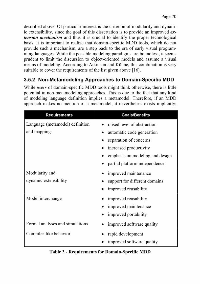
Page 70
described above. Of particular interest is the criterion of modularity and dynam-ic extensibility, since the goal of this dissertation is to provide an improved ex-tension mechanism and thus it is crucial to identify the proper technological basis. It is important to realize that domain-specific MDD tools, which do not provide such a mechanism, are a step back to the era of early visual program-ming languages. While the possible modeling paradigms are boundless, it seems prudent to limit the discussion to object-oriented models and assume a visual means of modeling. According to Atkinson and Kühne, this combination is very suitable to cover the requirements of the list given above [16].
3.5.2 Non-Metamodeling Approaches to Domain-Specific MDD While users of domain-specific MDD tools might think otherwise, there is little potential in non-metamodeling approaches. This is due to the fact that any kind of modeling language definition implies a metamodel. Therefore, if an MDD approach makes no mention of a metamodel, it nevertheless exists implicitly;
Requirements Goals/Benefits
Language (metamodel) definition and mappings
raised level of abstraction automatic code generation
separation of concerns increased productivity
emphasis on modeling and design partial platform independence
Modularity and dynamic extensibility
improved maintenance
support for different domains improved reusability
Model interchange improved reusability improved maintenance
improved portability
Formal analyses and simulations improved software quality
Compiler-like behavior rapid development improved software quality
Table 3 - Requirements for Domain-Specific MDD
Page 71
otherwise there would be neither an abstract nor a concrete syntax. However, it is possible that tools limit the role of the metamodel to a pure lan-guage definition inaccessible to the user, which exists only implicitly and is “hard-coded” into the MDD software. Such a metamodel does not have to be formally defined and will be largely ignored. In light of the requirements list for domain-specific approaches provided above, this has to be considered highly problematic. While the compiler-like behavior and simulations can be realized, the other requirements are not so easily met. First of all, model interchange is difficult without an explicit metamodel. While it is possible to come up with bridges which transform models from one format into another one, problems arise as soon as the metamodels are not equivalent, and in the context of domain-specific models such a situation is not unlikely. A better strategy is not to transform the models but to import a suitable metamodel along with the model into other tools. Nordstrom for example argues that a me-tamodel is in this case not only helpful but in fact required ([155], pg. 14). This exchange is not possible if the metamodel is only implicit. Additionally, the non-metamodeling approach lacks major extensibility poten-tial. While a mapping to code is possible without a known metamodel, user de-fined mappings are going to be difficult, as elements of the model are usually mapped to code based on their type, i.e., which element of the metamodel they instantiate. As a simple example, consider a code generation rule which maps UML classes to Java classes. Without access to a metamodel such a rule cannot be defined, because which elements in a model are to be considered “UML classes” is defined in the metamodel. Similarly, user extensions to the syntaxare quite difficult without access to the metamodel which represents the lan-guage definition unless one uses class libraries as described below. 3.5.2.1 Class Libraries and Inheritance The easiest domain-specific extension of a model, and the only one that can be used without explicit access to the metamodel, is to introduce domain-specific classes and use them as a basis for modeling by using generalization. While the classes do not form a language, class libraries can, to a certain extent, provide the same information as domain-specific language elements and can be used to describe user-defined domains. Indeed, since both inheritance and instantiation relationships are sometimes colloquially called “is-a” relationships, there is clearly some kind of conceptual overlap between the two concepts. The technique is illustrated by an example from the domain of art which will be used throughout this section. The domain contains the concepts Artist and Wor-kOfArt. Artists can be representatives of one or several Styles and be associated with one or more Regions. Each WorkOfArt also belongs to a Style. The con-cepts are assumed to carry a strongly defined meaning which can help in code generation.

Page 72
Figure 15 shows an example where the domain extension is realized with inhe-ritance. Artists of all kinds can be associated with styles and regions. WorksO-fArt (both Pictures and Statues) can also be associated with a Style. The model is kept simple and a genius like Michelangelo, who was both Painter and Sculptor, would not fit into this schema unless multiple inheritance is used. One advantage of using inheritance is the relatively low complexity (compared to ontological metamodel hierarchies as described in section 3.5.4.2). Also, the classes defined in the class library are not only available as superclasses for us-er-defined classes but can also be used directly in the user’s model. The latter is possible due to a relatively weak separation between the superclasses and the subclasses as opposed to that between types and their instances (see the strict-ness discussion in section 2.4.4 for further details). Whether this lack of separa-tion is an advantage or a disadvantage depends on individual interpretation. However, there are also other disadvantages. For example, the model in Figure 15 in no way forbids objects of Painter to have a link to a Statue object, even though this restriction was probably intended, thus introducing the opportunity for domain violations in the model. Extensive use of constraints can address this problem but reduces or negates the simplicity advantage of inheritance and does not scale well with larger models as the constraints are required for every class. Removing the association between Artist and WorkOfArt and replacing it with individual sub-associations solves the problem of false links but removes an im-portant aspect of the model, which is the information that artists are somehow related to works of art. Another disadvantage is the lack of control over the subclasses. Modelers who receive the classes above the parting line in Figure 15 as a class library have lit-tle if any guidance how to define their own classes. Due to the syntax of inherit-ance, the new classes can have arbitrary attributes, even ones that do not make any sense in the domain. Some people might not think of this liberty as a draw-back but it can be argued that it is an advantage to prohibit invalid cases instead of having undefined behavior.
Figure 15 - Inheritance as a Substitute for Instantiation
Page 73
A more serious drawback of this liberty is that the new attributes and new asso-ciations that are introduced do not depend on the class library in any way. This means that no information whatsoever exists about their domain-specific se-mantics. However, for code generation and model validation such information is very helpful if not mandatory. To recapitulate, inheritance and class libraries can be used to provide user de-fined metamodel extensions but are generally too unrestrictive to convey the full meaning of the newly introduced concepts. Thus, class libraries are only partial-ly suitable for dynamic extensions as well as domain-specific MDD environ-ments in general.
3.5.3 Single Metalayer Approaches Even when looking at conventional approaches, metamodeling takes a very cen-tral role in domain-specific MDD. According to Atkinson and Kühne it is even “an essential foundation” of MDD in general [16]. While this claim is debatable, primarily from the point of view of the users of MDD tools, many researchers try to improve existing MDD concepts by enhancing their metamodeling aspects (e.g., Atkinson and Kühne [16], Nordstrom [154], or the various works of the Precise UML Group [174]). However, metamodeling is complex, so restricting oneself to a single metalayer seems appealing. In one of his earlier works, Atkinson provides an argument against multi-level metamodeling, citing the fact that many of the concepts at the M2 level are often replicated at the M3 level and that it is possible to limit oneself to a single metalayer and still have the same modeling power [21]. While it is true that an end user is not interested in any higher modeling layers, for example, many UML users are probably una-ware of the existence and nature of its metamodels, the advantages of meta-modeling are generally seen in other directions as will be shown later on (see section 3.5.4). Single metalayer approaches cannot meet all of the requirements as described above. While the single metalayer approach is well-suited for the traditional “role of defining languages” [18] and can provide model simulation and compiler-like behavior, it is not sufficient for the other requirements. The first problem occurs with model tool interoperability which profits from a metalevel above the con-crete metamodels (cf. [18], [155] pg. 14). Just as M1 models can be loaded by tools based on the same M2 metamodel, serialized M2 metamodels can be used by tools which use the same M3 metamodel in which the M2 metamodels are defined. After dynamically loading a metamodel, models based on this metamo-del can be created or manipulated. The CDIF metamodel hierarchy was created for specifically this application. Without these additional metalayers, metamo-dels cannot be loaded; there simply exists no common format for the metamo-dels! The question of whether user-defined metamodel extensions can be realized with a single metalayer is not easily answered, even though some researchers are
Page 74
convinced of it (cf. [73]). There are several ways to allow the extension of me-tamodels, without allowing the user explicitly to metamodel, such as patterns or stereotypes as well as the class library approach described in the previous sec-tion. The following sub-sections provide a look at patterns and stereotypes and their suitability as domain-specific extension mechanisms. 3.5.3.1 Patterns According to Albin, design patterns are similar to metamodels, as both describe working principles which influence the structure of the code implementing the concepts of the model ([5], chapter 11). It is not unreasonable to imagine pat-terns which describe elements of a metamodel in such a way as to make them obsolete. For example instead of defining a metamodel with elements such as model, view, and controller, the Model View Controller (MVC) pattern (see [75]) could be applied to generic classes. Thus, a pattern can easily take the role of metamodel elements and a catalogue of patterns could serve as a domain-specific model extension. Overall, metamodels have far more structure and provide more consistency to their instances than patterns do. Albin states that metamodels are more generic than patterns, as there need not be a one-to-one correspondence between its con-cepts and elements within the source code of corresponding software. He also cites the fact that patterns can also be used in the context of metamodel hierar-chies ([5], chapter 11). Thus, the advantages of patterns and metamodel hierar-chies can easily be combined. Since the pattern approach is in effect little more than a variant on the stereotype concept, it will not be discussed in detail. 3.5.3.2 Stereotypes Stereotypes are a lightweight metamodel extension mechanism. Instead of in-troducing new metamodel layers, the existing metamodel is extended. By chang-ing only the immediate metamodel layer, there is no need for users to understand or be aware of the metamodel hierarchy. In the following discussion the UML 2.0 Profile concept of stereotypes is used (see [167], pp. 164-178). UML 2.0 ste-reotypes are considered lightweight, because they only allow adding new ele-ments to the metamodel but not to remove or alter already existing elements. In UML a stereotype is defined on the M2 layer of the linear UML metamodel hierarchy. While it can be argued that this makes stereotypes a multiple layer approach, the higher layers are transparent to the user of the tool and therefore stereotypes are included in this section. To define which model elements a par-ticular stereotype can be applied to, an instance of Extension is used to connect the stereotype to an M2 layer element such as Class or Association. For exam-ple, if a stereotype called <<Entity>> is connected to Class by an instance of Extension, instances of <<Entity>> can only be applied to classes (i.e., in-stances of Class).
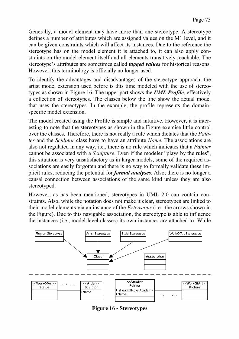
Page 75
Generally, a model element may have more than one stereotype. A stereotype defines a number of attributes which are assigned values on the M1 level, and it can be given constraints which will affect its instances. Due to the reference the stereotype has on the model element it is attached to, it can also apply con-straints on the model element itself and all elements transitively reachable. The stereotype’s attributes are sometimes called tagged values for historical reasons. However, this terminology is officially no longer used. To identify the advantages and disadvantages of the stereotype approach, the artist model extension used before is this time modeled with the use of stereo-types as shown in Figure 16. The upper part shows the UML Profile, effectively a collection of stereotypes. The classes below the line show the actual model that uses the stereotypes. In the example, the profile represents the domain-specific model extension. The model created using the Profile is simple and intuitive. However, it is inter-esting to note that the stereotypes as shown in the Figure exercise little control over the classes. Therefore, there is not really a rule which dictates that the Pain-ter and the Sculptor class have to have an attribute Name. The associations are also not regulated in any way, i.e., there is no rule which indicates that a Paintercannot be associated with a Sculpture. Even if the modeler “plays by the rules”, this situation is very unsatisfactory as in larger models, some of the required as-sociations are easily forgotten and there is no way to formally validate these im-plicit rules, reducing the potential for formal analyses. Also, there is no longer a causal connection between associations of the same kind unless they are also stereotyped. However, as has been mentioned, stereotypes in UML 2.0 can contain con-straints. Also, while the notation does not make it clear, stereotypes are linked to their model elements via an instance of the Extensions (i.e., the arrows shown in the Figure). Due to this navigable association, the stereotype is able to influence the instances (i.e., model-level classes) its own instances are attached to. While
Figure 16 - Stereotypes
Page 76
the shortcomings described above can all be avoided this way, the addition of many very similar, but still slightly distinct, constraints counteracts the simplici-ty of the stereotype concept. The advantages of stereotypes are twofold. First, they are relatively easy to use. Second, they are easy to implement in MDD tools, even if those tools do not use a fully-fledged metamodel internally (see [17]). One of their drawbacks (as iden-tified by Atkinson and Kühne) is that they are easily abused to make statements about an object instead of a class, leading to many unnecessary singleton classes in a model which are only distinguished by the attributes of the stereotype [17]. Another problem is that they exercise little control over the classes they are at-tached to unless constraints are provided by the user. Cook holds a similar view, feeling that UML profiles offer only a “very limited level of extensibility” [51], which might be explained by the fact that, while the stereotype mechanism al-lows almost arbitrary extensions, it does not provide any mechanisms to define their meaning, i.e., language support for a semantic description (cf. Harel and Rumpe [106], [107]). However, the same argument might be applied to the other extension approaches described in this section, so it is not relevant for the com-parison at hand. Nevertheless, it should be noted that people with metamodeling experience seem to dislike stereotypes, Völter for example sees the use of Pro-files as less “conceptually clean” [208] than the use of fully fledged metamo-dels. Overall, the quality of the stereotype approach depends a lot on personal prefe-rence. Profiles are very lightweight but can be fleshed out by adding constraints. This means that if the metamodel is very generic or a lot of information is pro-vided in the form of natural language, stereotypes are advantageous. If, on the other hand, the metamodel should carry a lot of semantic information, stereo-types will produce hard-to-maintain results due to the addition of many con-straints. As domain-specific MDD environments need semantic information for code generation, stereotypes are not a good solution. Pragmatics might point out in this context that Profiles, and therefore stereo-types, are widely accepted and apparently sufficient for practical use. Kent in particular points out their great flexibility [131]. However, this view is only par-tially correct. Duddy, for example, claims that many of the UML Profiles de-signed so far actually go beyond this simple extension mechanism. He claims that the Enterprise Application Integration (EAI) UML Profile [170] really uses its own metamodel which does not reuse UML and cites the EDOC Profile as another example where an originally fully-fledged metamodel was “shoehorned” into the Profile context ([61], also see Kent’s view on EAI and EDOC in [131]). If these claims are true, they provide a strong argument for the insufficiency of stereotypes as well as showing that stereotypes can be used as a “front end” for more complex extension mechanisms.
Page 77
3.5.4 Metamodeling Hierarchy Approaches As discussed in the previous section, the common single metalayer approaches are not very suitable for model exchange and their domain-specific extensibility has problems with providing sufficient levels of semantics. Metamodel hierar-chies not only offer all the advantages provided by single metalayer approaches but also address these open problems. The fact that metamodel hierarchies offer a solution for model interchange be-tween tools has already been mentioned, the most common examples being CDIF and MOF. They also provide a good platform for dynamic extension me-chanisms. Völter states that metamodeling supports several key aspects of MDD, namely architecture-centric modeling, tool adaptation, model validation, model transformation, and code generation. A metamodel also facilitates do-main-specific modeling by providing an infrastructure to define new modeling languages [208]. Given a generic “metametamodel”, it is possible to use the same infrastructure to design models for domains which have vastly different or even contradictory semantics (cf. Cook [50]). A custom metamodel can be used with all the benefits a specialized modeling language offers within a known tool framework. Duddy proposes a vision for MDA where models based on custom metamodels can be designed, then transformed to a PSM common to all meta-models to use for code generation [61]. This vision of UML as a “family of lan-guages” [61] is also advocated in other forms by Atkinson and Kühne [17], Völter [208], Nordstrom ([154], [155]), Frankel [72], Kent [131], Clark et al. [48] and many others. A metamodel hierarchy not only allows the creation of new domain models but also the maintenance of existing ones to incorporate possible changes (cf. Nordstrom [155], pg. 3). A very interesting interpretation of metamodel hierarchies is given by Albin who sees a possible parallel to knowledge management ([5], chapter 11). A sim-ilar opinion is expressed by Chandrasekaran et al. who see a gradual conver-gence between ontologies and what they call “object systems”, i.e., OO-models [44] and also by Obrenovic et al. [156] and Bézivin ([30], pp. 41, 54, and 64). Another indicator is the OMG’s request for proposal regarding a metamodel for ontologies called Ontology Definition Metamodel (ODM) [164]. While this si-milarity cannot be discussed in detail here, it should be noted that this parallel could possibly be exploited to use artificial intelligence to enhance code genera-tion from models. There are at least two types of metamodeling hierarchies which are of interest for domain-specific MDD. The first is the classical metamodel hierarchy with four layers, as introduced by CDIF and adopted by MOF. While it has certain shortcomings, it is well-established and has found its way into OMG’s MDA approach. The other type of metamodel hierarchy relevant in this context is a nonlinear hierarchy with a focus on ontological metamodeling.
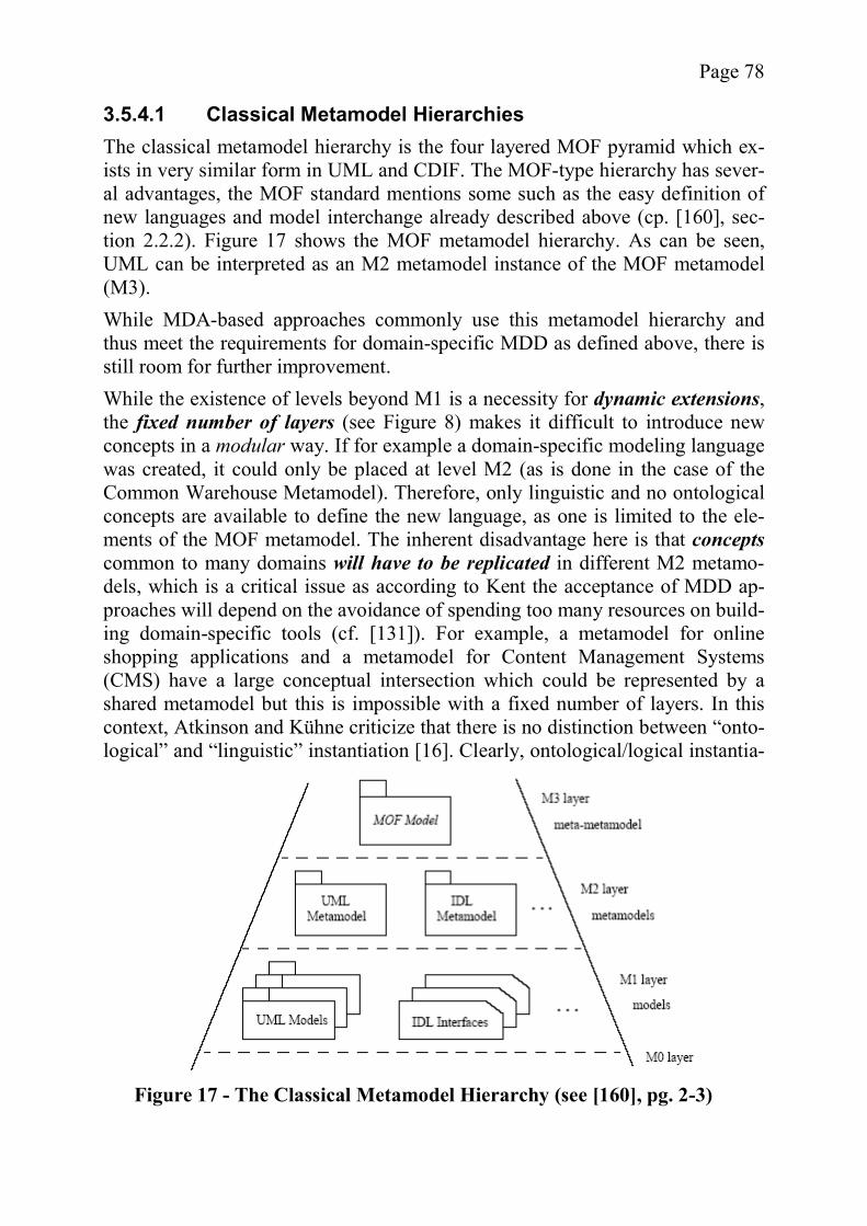
Page 78
3.5.4.1 Classical Metamodel Hierarchies The classical metamodel hierarchy is the four layered MOF pyramid which ex-ists in very similar form in UML and CDIF. The MOF-type hierarchy has sever-al advantages, the MOF standard mentions some such as the easy definition of new languages and model interchange already described above (cp. [160], sec-tion 2.2.2). Figure 17 shows the MOF metamodel hierarchy. As can be seen, UML can be interpreted as an M2 metamodel instance of the MOF metamodel (M3). While MDA-based approaches commonly use this metamodel hierarchy and thus meet the requirements for domain-specific MDD as defined above, there is still room for further improvement. While the existence of levels beyond M1 is a necessity for dynamic extensions, the fixed number of layers (see Figure 8) makes it difficult to introduce new concepts in a modular way. If for example a domain-specific modeling language was created, it could only be placed at level M2 (as is done in the case of the Common Warehouse Metamodel). Therefore, only linguistic and no ontological concepts are available to define the new language, as one is limited to the ele-ments of the MOF metamodel. The inherent disadvantage here is that conceptscommon to many domains will have to be replicated in different M2 metamo-dels, which is a critical issue as according to Kent the acceptance of MDD ap-proaches will depend on the avoidance of spending too many resources on build-ing domain-specific tools (cf. [131]). For example, a metamodel for online shopping applications and a metamodel for Content Management Systems (CMS) have a large conceptual intersection which could be represented by a shared metamodel but this is impossible with a fixed number of layers. In this context, Atkinson and Kühne criticize that there is no distinction between “onto-logical” and “linguistic” instantiation [16]. Clearly, ontological/logical instantia-
Figure 17 - The Classical Metamodel Hierarchy (see [160], pg. 2-3)
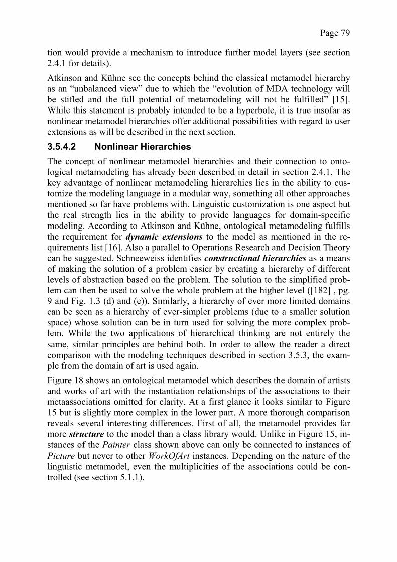
Page 79
tion would provide a mechanism to introduce further model layers (see section 2.4.1 for details). Atkinson and Kühne see the concepts behind the classical metamodel hierarchy as an “unbalanced view” due to which the “evolution of MDA technology will be stifled and the full potential of metamodeling will not be fulfilled” [15]. While this statement is probably intended to be a hyperbole, it is true insofar as nonlinear metamodel hierarchies offer additional possibilities with regard to user extensions as will be described in the next section. 3.5.4.2 Nonlinear Hierarchies The concept of nonlinear metamodel hierarchies and their connection to onto-logical metamodeling has already been described in detail in section 2.4.1. The key advantage of nonlinear metamodeling hierarchies lies in the ability to cus-tomize the modeling language in a modular way, something all other approaches mentioned so far have problems with. Linguistic customization is one aspect but the real strength lies in the ability to provide languages for domain-specific modeling. According to Atkinson and Kühne, ontological metamodeling fulfills the requirement for dynamic extensions to the model as mentioned in the re-quirements list [16]. Also a parallel to Operations Research and Decision Theory can be suggested. Schneeweiss identifies constructional hierarchies as a means of making the solution of a problem easier by creating a hierarchy of different levels of abstraction based on the problem. The solution to the simplified prob-lem can then be used to solve the whole problem at the higher level ([182] , pg. 9 and Fig. 1.3 (d) and (e)). Similarly, a hierarchy of ever more limited domains can be seen as a hierarchy of ever-simpler problems (due to a smaller solution space) whose solution can be in turn used for solving the more complex prob-lem. While the two applications of hierarchical thinking are not entirely the same, similar principles are behind both. In order to allow the reader a direct comparison with the modeling techniques described in section 3.5.3, the exam-ple from the domain of art is used again. Figure 18 shows an ontological metamodel which describes the domain of artists and works of art with the instantiation relationships of the associations to their metaassociations omitted for clarity. At a first glance it looks similar to Figure 15 but is slightly more complex in the lower part. A more thorough comparison reveals several interesting differences. First of all, the metamodel provides far more structure to the model than a class library would. Unlike in Figure 15, in-stances of the Painter class shown above can only be connected to instances of Picture but never to other WorkOfArt instances. Depending on the nature of the linguistic metamodel, even the multiplicities of the associations could be con-trolled (see section 5.1.1).
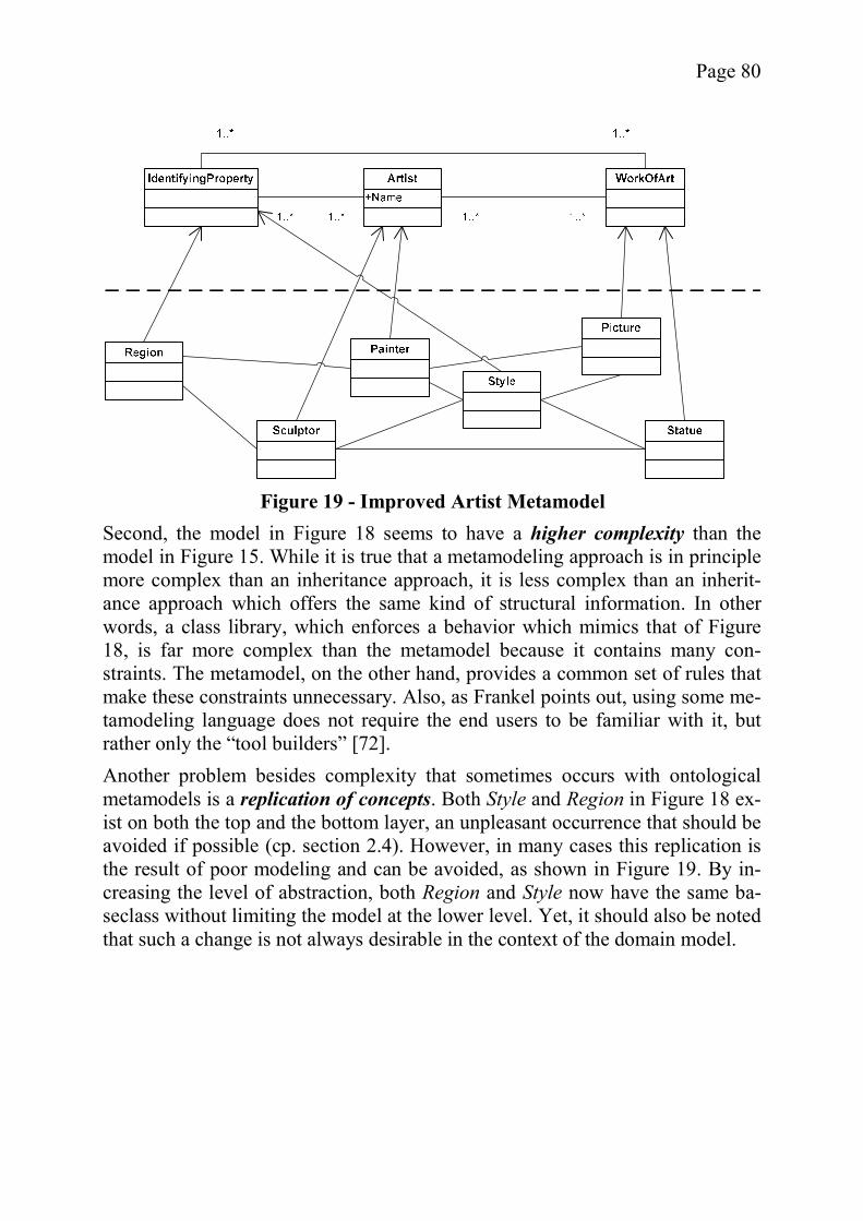
Page 80
Second, the model in Figure 18 seems to have a higher complexity than the model in Figure 15. While it is true that a metamodeling approach is in principle more complex than an inheritance approach, it is less complex than an inherit-ance approach which offers the same kind of structural information. In other words, a class library, which enforces a behavior which mimics that of Figure 18, is far more complex than the metamodel because it contains many con-straints. The metamodel, on the other hand, provides a common set of rules that make these constraints unnecessary. Also, as Frankel points out, using some me-tamodeling language does not require the end users to be familiar with it, but rather only the “tool builders” [72]. Another problem besides complexity that sometimes occurs with ontological metamodels is a replication of concepts. Both Style and Region in Figure 18 ex-ist on both the top and the bottom layer, an unpleasant occurrence that should be avoided if possible (cp. section 2.4). However, in many cases this replication is the result of poor modeling and can be avoided, as shown in Figure 19. By in-creasing the level of abstraction, both Region and Style now have the same ba-seclass without limiting the model at the lower level. Yet, it should also be noted that such a change is not always desirable in the context of the domain model.
Figure 18 - A Metamodel for the Domain of Art Figure 19 - Improved Artist Metamodel
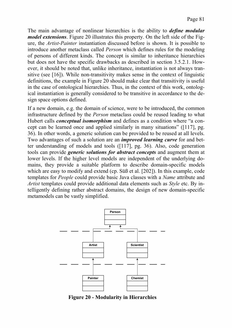
Page 81
The main advantage of nonlinear hierarchies is the ability to define modular model extensions. Figure 20 illustrates this property. On the left side of the Fig-ure, the Artist-Painter instantiation discussed before is shown. It is possible to introduce another metaclass called Person which defines rules for the modeling of persons of different kinds. The concept is similar to inheritance hierarchies but does not have the specific drawbacks as described in section 3.5.2.1. How-ever, it should be noted that, unlike inheritance, instantiation is not always tran-sitive (see [16]). While non-transitivity makes sense in the context of linguistic definitions, the example in Figure 20 should make clear that transitivity is useful in the case of ontological hierarchies. Thus, in the context of this work, ontolog-ical instantiation is generally considered to be transitive in accordance to the de-sign space options defined. If a new domain, e.g. the domain of science, were to be introduced, the common infrastructure defined by the Person metaclass could be reused leading to what Hubert calls conceptual isomorphism and defines as a condition where “a con-cept can be learned once and applied similarly in many situations” ([117], pg. 36). In other words, a generic solution can be provided to be reused at all levels. Two advantages of such a solution are an improved learning curve for and bet-ter understanding of models and tools ([117], pg. 36). Also, code generation tools can provide generic solutions for abstract concepts and augment them at lower levels. If the higher level models are independent of the underlying do-mains, they provide a suitable platform to describe domain-specific models which are easy to modify and extend (cp. Süß et al. [202]). In this example, code templates for People could provide basic Java classes with a Name attribute and Artist templates could provide additional data elements such as Style etc. By in-telligently defining rather abstract domains, the design of new domain-specific metamodels can be vastly simplified.
Person
Artist
Painter
Scientist
Chemist
Figure 20 - Modularity in Hierarchies
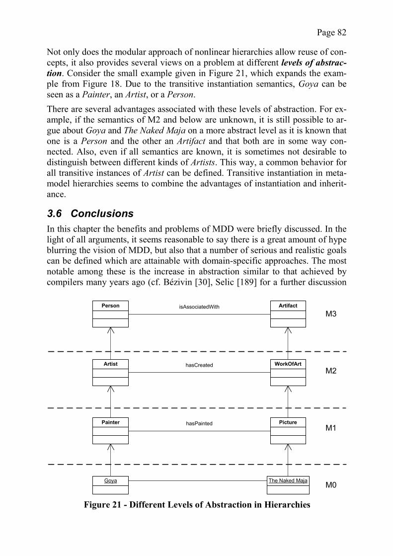
Page 82
Not only does the modular approach of nonlinear hierarchies allow reuse of con-cepts, it also provides several views on a problem at different levels of abstrac-tion. Consider the small example given in Figure 21, which expands the exam-ple from Figure 18. Due to the transitive instantiation semantics, Goya can be seen as a Painter, an Artist, or a Person. There are several advantages associated with these levels of abstraction. For ex-ample, if the semantics of M2 and below are unknown, it is still possible to ar-gue about Goya and The Naked Maja on a more abstract level as it is known that one is a Person and the other an Artifact and that both are in some way con-nected. Also, even if all semantics are known, it is sometimes not desirable to distinguish between different kinds of Artists. This way, a common behavior for all transitive instances of Artist can be defined. Transitive instantiation in meta-model hierarchies seems to combine the advantages of instantiation and inherit-ance.
3.6 Conclusions In this chapter the benefits and problems of MDD were briefly discussed. In the light of all arguments, it seems reasonable to say there is a great amount of hype blurring the vision of MDD, but also that a number of serious and realistic goals can be defined which are attainable with domain-specific approaches. The most notable among these is the increase in abstraction similar to that achieved by compilers many years ago (cf. Bézivin [30], Selic [189] for a further discussion
Painter
Artist
Picture
WorkOfArt
hasPainted
hasCreated
Person Artifact
Goya The Naked Maja
isAssociatedWith
M0
M1
M2
M3
Figure 21 - Different Levels of Abstraction in Hierarchies

Page 83
of the hype and reality of MDD). The following statement by Bézivin nicely de-scribes the potential of MDD/MDA: “MDA is not going to solve all the problems in IT. But it is going to allow somesolutions with better efficiency than other technologies” ([30], pg. 52, emphasis added). It has been shown that domain-specific MDD shows the most promise regarding this goal, but that a domain-specific tool has to be able to handle different do-mains by providing a suitable extension mechanism for which several alterna-tives exist. In the next section, the domain of Web applications will be intro-duced as an example for a rather active field of MDD research, along with sev-eral examples of existing approaches. After that, there is a sufficient base to showcase the proposed model extension mechanism using a domain suitable for MDD.
Page 84
4 An Analysis of the Web Application Domain In the previous chapter, the general concept of MDD was introduced and after a thorough analysis it became obvious that domain-specific approaches in well-specified domains are one of the best starting points for MDD. Web application design and implementation is an area which seems to be a popular target for cur-rent MDD research, possibly due to the great maturity of Web design methodol-ogies, which can, with some effort, be adapted to include dynamic behavior. MDD approaches also profit from the use of frameworks (cf. Völter [209]), another field where Web engineering has a lot to offer. This chapter (which further elaborates on the arguments provided by Gitzel et al. [89]) starts with a brief discussion of Web applications and their unique proper-ties as opposed to general software, leading to a list of specific problems that must be addressed. In turn, several conventional approaches for the realization of Web applications will be examined, as well as how each of them helps with solving the domain’s inherent problems. In section 4.3, an analysis is conducted as to how MDD can both incorporate the existing approaches and address the open issues of the field. The chapter ends with a summary and conclusion.
4.1 Properties and Problems of Web Applications The World Wide Web (WWW) has revolutionized the life of modern society. From its roots as a largely text-based collection of information to its current in-carnation as a worldwide multimedia-capable client-server application, the tech-nology behind the WWW has undergone vast changes without abandoning its basic paradigm. It is for this reason that “Web projects” tend to differ from other software projects, giving rise to some doubt about the suitability of standard software engineering processes for this field (cf. Glass [97], Deshpande and Hansen [58]). Regardless of whether this objection is true or not, the unique as-pects of Web applications should be analyzed and taken into consideration by any domain-specific approach in this field. The advantages of Web applications are the introduction of a standard client, which reduces both the required training for users and the cost to create an ap-plication’s interface ([58], [135], chapter 3), the ability to perform all updates in one place (i.e., at the server) ([135], chapter 3), and increased application porta-bility ([135], chapter 3). On the other hand, there are also new kinds of prob-lems, some of which are technical and some of which are social or human-computer interaction issues.
4.1.1 Technical Properties and Problems The unique paradigm of Web application development leads to a couple of tech-nical problems that need to be addressed in order to avoid complications during the development of the software and its maintenance. Some of the key features of Web applications are the reliance on the Hypertext Transfer Protocol
Page 85
(HTTP) and Hypertext Markup Language (HTML) for communication and the inhomogeneous client-side environment whose exact range of properties, both technical and human-related, is most likely unknown due to a great number of different browsers, plugins, and platforms as well as the global nature of the Web (cf. [58], [135], chapter 3). Offut identifies a similar heterogeneity on the server side due to the distributed use of various technologies [159]. Another in-teresting difference to traditional software is the fact that it is technically trivial to switch to another server providing the same service without significant loss of time or money ([97], [151], pg. 10, [159]). These unique properties lead to several problems that have to be addressed in order to produce successful Web applications. The lack of state incurred by the use of HTTP is the reason for some of the most fundamental problems of Web engineering. Originally, the Web was intended for the display and intelligent linking of text. When one considers that the Web is a hypertext system, the concept of which goes back to Vannevar Bush’s hypo-thetical MEMEX machine for storing and rearranging information from printed books in the 1930ties (see [130]), it is not surprising to experience a vast con-ceptual gap to modern Web applications (cf. [80]). While the basics of the lack of state issue have been addressed by using cookies or Uniform Resource Loca-tor (URL) extensions (cf. [135], chapter 3) there are still some problems to ad-dress in individual implementations. For example, flow control is complicated because back buttons, caching, and stored URLs allow virtually any state transi-tion ([135], chapter 3, [151], pg. 25). Many researchers describe compatibility issues due to the varying capability of the clients in dealing with the information transmitted from the server side. Be-sides the different browser versions with varying script and HTML interpreta-tions, screen resolutions and color settings may vary. Of even greater impact are variations in the capability of the hardware, for example with regard to band-width and the quality of the output devices, which can range from small mobile phones supporting the Wireless Application Protocol (WAP) to non-visual out-put media, such as screen readers for the blind (cf. [58], [80], [135], chapter 3, [194], pg. 42-44). As a consequence, software tests are a lot harder to perform than in the case of traditional software ([58], [97]). Even though testing is more difficult, it still makes sense, even from a business standpoint, to go through this additional effort. Reliability is a major factor in Web site quality, the reason being that users can easily switch to other Web sites ([27], [80], [159]). Given the unstable technological foundation of Web applica-tions, reliability is more difficult to achieve than in some other fields of software engineering, where fewer changes occur [159]. A related problem is performance, as people are unwilling to wait long for pag-es to load. While Offut points out that this is not so much a problem on the serv-er side, as the bottleneck is the bandwidth [159], the latter is hard to anticipate.

Page 86
Therefore, Web pages should be designed to load in reasonable time, regardless of the network capabilities and the performance of the client ([58], [149], [151], pp. 27-35, also cf. [27]). On the other hand, more complex applications might very well have server-side performance problems when serving a large number of clients, at which point the issue of scalability has to be considered, even if only as a basis for future expansions ([80], [135], chapter 3, [159]). Due to the importance of uninterrupted reliability, performance, and scalability, Web applications undergo constant maintenance instead of fixes being grouped in release packages ([80], [97], [146], [159]). Besides added workload, compati-bility issues have to be considered [159] and the user interface should be de-signed in a way to accommodate frequent changes [146]. Also, maintenance should not reduce the availability of the page. Any down time will lead to reve-nue losses, since people cannot use the site during that time and are likely to look elsewhere [159]. Security issues are of particular importance when developing Web applications ([27], [58], [80], [159]), because the loss of customer information can lead to loss of credibility, legal problems, repair cost, and revenue losses (cf. Offut [159]). Lack of security is not only a danger to the site itself but also to the in-ternet as a whole, making the internet one of most important problem areas con-nected to information technology today (cf. Neumann [145]).
4.1.2 Usability Issues and Properties While usability problems definitely exist on the Web (and there are many papers and Web sites identifying them), there is a high level of disagreement on the level of abstraction and the required scientific foundation to use for their diag-nosis. For example, some sources see the problems in the details (e.g., Nielsen [149], [150], [151], [152], and [153]) while others believe in guidelines situated at a higher level (e.g., Shneiderman [194], pg. 65). In addition, some sources are opposed to generic guidelines at all, demanding rigorous empirical study (cf. Ivory et al. [124]) while others indicate that guidelines can be given if backed up by empirical testing (cf. Catarci and Little [39], Neuwirth and Regli [146], Niel-sen [151], pp. 10-11, and the metrics given in [125]). An extreme position is held by Paolini who questions the value of empirical studies for Web usability on the ground that, due to the global nature of the Web, it is impossible to find representative users of the application [172]. However, such discussions are beyond the scope of this work and the usability issues considered are those most commonly identified in the literature. It should be noted that the focus of the following information is on issues partic-ular to a Web environment and that it is likely that some of these goals are con-flicting with external conditions. For example, Becker and Mottay point out that the strategic goals of an organization might place less value on some proposi-tion or the other, in particular, if time-to-market is deemed an important success factor ([27], [28]).

Page 87
4.1.2.1 Consistency An important, and maybe even the central factor for a Web site’s usability, is its consistency in visual design and behavior, both by itself and with regard to the Web as a whole ([27], [78], [194], pg. 65). Without consistency, one of the main advantages of the Web, the uniform client interface, is partially or completely negated. While the desire to stand out of the crowd and to attract customers is a legitimate one, it should not be achieved by reducing the usability of the site. A consistent Web site supports a high degree of predictability, enhancing the us-er’s ability to foretell what results the interaction with the Web page will yield ([194], pg. 65, [78]). Internal homogeneity is achieved by giving the pages of a Web site the same theme and by establishing conventions such as creating a common layout or us-ing the same icon for the same purpose every time [35]. As a rule of thumb, Garzotto et al. advise treating “conceptually similar elements in a similar fashion and conceptually different elements differently” [78]. Since many organizations have established precise guidelines for a “corporate identity”, at least a consis-tent look can currently be considered standard in professional Web pages. Consistency with the other sites on the Web is also important, because few users are willing to learn how to use a Web application which differs from what they are used to. For this reason it is a bad idea to deviate from “Web conventions” by using different link colors [149] and introducing unexpected link behavior such as pop-up windows [152]. Also, there is currently a wide range of estab-lished “design standards” such as a common layout [27] including a logo and a navigation sidebar [150] or naming conventions [27] such as calling the main page of a site the “homepage”. 4.1.2.2 Navigability and Site Structure The ability to reach the intended target page is a major factor for usability and many researchers identify navigation and site structure as two of the main usa-bility concerns in Web applications (cf. Becker and Berkemeyer [27], Nielsen [151], and Paolini [172]). Nevertheless, many Web sites still suffer from prob-lems in this context, although the establishment of the “Web conventions” men-tioned oben has helped to make this problem less pronounced. The purpose of navigation tools such as a sidebar with links is to give the user the required sense of orientation, not only identifying pages he can reach but also the current position within the Web site ([151], pg. 188). Without a solid concept of the structure of a Web site, users will quickly become lost due to the additional dimensions of movement as opposed to the forward and back in tradi-tional text ([204], [206]). Nielsen identifies several types of Web site structures such as trees and tables, both of which are commonly encountered on the Web. While a tree-based navi-gation will lead users deeper into increasingly concrete categories, table-like
Page 88
structures define categories based on the values of the table’s attributes. A linear structure, which is similar to that of traditional media, is considered to be useful only in exceptional cases ([151], pp. 15, 200-207). Regardless of the structure, a good homepage, as the starting point for most users, is important and should give a good overview of the site ([151], pg. 166). In fact, the purpose of a Web application should be immediately obvious to an incoming user ([153], [204]). The categories needed for the establishment of a navigational structure are not always easy to define. Nielsen proposes the use of aggregations, summaries, fil-tering, or an example-based presentation ([151], pp. 221). However, it might al-so be useful to allow the users to dynamically define their own categories for navigation [153]. The opinion on the proper number of categories differs. Shneiderman believes that it is better to create shallow trees rather than deep ones to allow users to reach their intended goal with minimal effort ([194], pg. 67). Similarly, Garzotto et al. identify the richness of an application, i.e. the ab-undance of information items and multiple ways to reach them as a good feature [78]. On the other hand, Borges et al. state that there should not be too many links on a single page to avoid cluttering [35], which necessarily leads to deeper trees. Once a Web site has been designed, it is important to consider how to make its structure visible to the user by establishing a navigational structure that mirrors the internal one. This goal cannot be reached by including arbitrary links. Ra-ther, the links should be organized in a way which emphasizes the structure, us-ing navigational patterns such as site maps [149], indices [104], or guided tours [104]. However, not all links are used for structural navigation within the site. Other link types identified by Nielsen are associative links, which lead to pages containing additional information on a certain topic, and reference links ([151], pg. 51). These external links add to the quality of the page but they must be cho-sen carefully (cf. [151], pg. 67 and pg. 70). In addition, the design and realization of individual links can also incur prob-lems if not done properly. Generally, the name of the link should be concise and hint at where it leads to [35], giving the application what Garzotto et al. call self-evidence [78]. On the other hand, there should be no explanatory comments near the links [35]. Typical problems are pages that link to themselves [153], orphan pages (i.e. pages whose parent Web site cannot be identified by those who arrive there from a search engine) [153], and broken links. Based on these insights, it is possible to come up with a recommendation similar to that of Theng, who suggests designing pages with meaningful headers and footers with origin, date, copyright info etc. (also cf. [35]), text-labeled naviga-tion aids, making heavy use of indices, and other landmarks [204]. Nielsen, on the other hand, considers navigation more of a necessary evil, thus feeling that the links should not take up too much room on a page ([151], pg. 18). Also,
Page 89
about half the users prefer to use the search function rather than navigate so the search interface should be easily reachable from any page ([151], pp. 224). 4.1.2.3 Visual Presentation The visual presentation is a very important aspect of usability ([27], [49], [151]), covering not so much aesthetic quality but rather how supportive the visual de-sign is for solving the problems the interface was designed for. In fact, Constan-tine and Lockwood claim that if the aesthetic design is considered more impor-tant than usability, the site quality will suffer for it [49]. The same can be said about a focus on technological innovation, which often implies the addition of new multimedia features as opposed to quality content and service, particularly if this focus leads to errors or problems for the user ([149], [150]). When look-ing at problems of visual presentation, psychological aspects play an important role and a lot of literature exists on how to properly design the visual presenta-tion for all kinds of media. However, these complex issues are beyond the scope of this work and only a few general examples will be given. It has already been mentioned in section 4.1.1 and the introduction of 4.1, that the performance of a Web application is directly influenced by the graphical opulence of a Web page. Another aspect, which should be taken into account when designing the visual presentation, is the heterogeneous nature of the clients. It is prudent to choose a design for Web pages suitable for a wide variety of heterogeneous client technologies. This design strategy can be pursued by using generically applicable Web pages, which have properties such as scalable fonts [152], or by dynamically creating different versions, including printable versions for different paper formats ([151], pp. 93), using some form of style sheets ([151], pp. 27-36 and pg. 77). Besides these more technical issues, the visual design should support the in-tended task of the user of a page. For example, the use of high contrast and the avoidance of distractions such as animations can help improve readability ([115], [149], [151], pp. 126, 143). Ivory et al. even claim “good pages have rel-atively fewer graphics” [124]. On the other hand, Horton points out that by us-ing interactive animations, the advantages of computer applications over tradi-tional paper media can be fully realized [115]. These positions are not necessari-ly mutually exclusive. It seems prudent to use graphics sparingly and activate animations only when the user is interacting with a graphic. Besides graphical presentation, pages are also often inconvenient with regard to “what-if support”. Nielsen feels that many users would benefit from being able to compare products listed in a table but mentions that many sites will only dis-play a single product at a time. For example, many airline sites only allow choosing a specific date for a flight instead of a range [153]. Generally, a Web page’s text should be written in such a way that it allows the reader to skim over it and easily identify the parts relevant for him. This can be done by keeping the text short and dividing it into easily graspable chunks. The
Page 90
highlighting of keywords, clear categories and terms, as well as the limitation to one idea per paragraph, are additional measures to improve readability ([151], pp. 101-111, also cf. [35]). Usability is also improved by avoiding scrolling ([149], [152]) and eliminating headers that take up too much room [35]. 4.1.2.4 Internationalization Given the global nature of the Web, internationalization is a major concern for those Web sites intended for a multi-cultural and heterogeneous audience. How-ever, internationalization is not limited to language translations but also includes a consideration of the cultural background of potential users [204]. A lot of work has been done in the field of internationalization already. For example, Becker and Mottay cite global marketing strategies such as those of McDonald’s and Coca Cola as good examples for successful localization. The principles of these strategies in turn offer a good basis for Web localization [28]. Marcus and Gould propose using cultural dimensions such as those identified by Hofstede [113] as a basis for guidelines [138]. Rosson and Carroll identify two approaches to internationalization, i.e., standar-dization and localization. Standardization helps facilitate the design process by offering standard solutions and best practices and makes it easier for users to adapt to new systems. However, the variations of design are constrained and in-novations possibly blocked ([178], chapter 10.2.1). Localization on the other hand strengthens cultural diversity but is more expensive than a global interface. While avoiding culturally offensive symbols and terminology is also possible for standardized user interfaces, other issues such as language, as well as formats for things such as date and currency are not so easily addressed ([178], chapter 10.2.2). A similar distinction into two internationalization approaches is also proposed by Nielsen ([151], pp. 315). Becker and Mottay offer three solutions for locali-zation. The first, a common design for all sites, is very similar to standardization as described above, except for the adaptation of the site language. Becker and Mottay also suggest a custom design for each site and a hybrid solution where only parts of the Web application are customized [28]. An effort to provide internationalization incurs several problems. The most ob-vious ones are the added workload, redundancy, and as a result additional costs [28]. Concrete design problems include the cultural influence on page layout, colors, and terminology (cf. [28], [138]). For example, Arabian or Hebrew ap-plications will have a layout which reflects the different direction of reading2
(cf. [28], [54], pg. 235). The choice of color reflects the cultural background as well, e.g. the color red acts as a warning signal in Western cultures but not in Asian ones (cf. [28], [114], [115]). Similarly, certain symbols such as hand ges-
2 For an example see Al Jazeera (http://www.aljazeera.net/)

Page 91
tures used in icons can be highly offensive in some cultures ([54], pg. 235, [115]). A special consideration of terminology is required because literal trans-lations sometimes sound archaic or are inappropriate in the context where they are used [28]. The locally applicable measurement units and formats for time and date should be used as well as the time zones considered if events are an-nounced ([43], [151], pg. 318, [178], chapter 10.2.2). Finally, certain processesmight vary from country to country, such as the point of time when taxes are added to a price and how they are presented in a bill [43]. While most cultural influences on Web page design stem from cultural symbol-ism or local customs, it is also possible to classify cultures according to certain criteria, or cultural dimensions, and use this information to further localize the interface. Marcus and Gould propose to use information on factors such as the role of the individual as opposed to the collective, or a culture’s tendency to-wards strong hierarchies as a basis for Web design. For example, a culture with strong hierarchies would be more likely to dedicate part of a site to information on the leaders of a Web site’s organization (cf. [138]). Other cultural issues include different ethical values such as privacy concerns or local laws which should be addressed appropriately, for example by displaying the proper disclaimer messages [43]. Also, there are regional differences in available technology that should be taken into account. Becker and Mottay sug-gest enhancing user profiles with regional and cultural information, including information on the typical bandwidth available in the user’s region [28]. 4.1.2.5 Accessibility Increasingly, accessibility has become an important issue. In fact, many re-searchers worldwide identify barriers to accessibility as key usability problems (e.g. Becker and Berkemeyer [27], Deshpande and Hansen [58], Ginige and Mu-rugesan [80], Rosson and Carroll [178], and Shneiderman [194], pg. 42). Acces-sibility helps limit the problem of the digital divide [178], which is particularly important in contexts such as e-government ([194], pg. 38). However, accessi-bility also makes sense from an economic point of view, as it draws customers who are likely to stay with a site that caters to their specific needs ([151], pp. 298, [194], pg. 42). Many aspects of accessibility are technical, e.g., there might be a need for spe-cial hardware for disabled persons (see section 4.1.1). However, accessibility is also a usability problem, because the Web page design has to specifically sup-port special output devices, e.g. by providing useful and short ALT text for pic-tures in order to allow the efficient use of so-called screen readers for the blind [153]. Other helpful properties in Web pages are dynamic enlargement, larger fonts, greater contrast, and larger mouse targets [178]. Additionally, Nielsen feels that a focus on content rather than presentation can also help accessibility ([151], pp. 298).
Page 92
Shneiderman points out two interesting aspects, which suggest addressing acces-sibility issues from the early design stages forward. As many of the accessibility guidelines intersect with those for general usability, an accessible Web site can also benefit non-disabled users. Also, accessibility touches some core aspects of a Web application’s code. Thus, adding accessibility at later stages is going to be far more expensive than incorporating it from the beginning ([194], pg. 42). 4.1.2.6 User- and Domain-Related Issues According to several researchers, it is beneficial if information can be presented in different ways to accommodate the different skill levels and personalities of readers, possibly as part of a personalization feature ([67], [194], pg. 44, also see [27]), with the goal focused on making applications easy to use [78]. Becker and Mottay claim that a user’s perception of usability depends on his or her pro-file, which includes not only the skill level but also traits such as gender or age [28]. Personalization means that an adaptation of the Web pages sent to the client is based on the personal parameters of the user. The simplest example is addressing the user by his personal name. More sophisticated examples include added shortcuts for professional users. Of equal importance is the influence of the domain (cf. [124], [179]). According to Roth et al. “considerations of the users and the tasks they will be performing […] should be central drivers for system design specification” ([179], pg. 164). The goals and constraints in the application domain play a central role [179]. In a similar vein, Rosson and Carroll state that “user interface design issues depend on the context of use” ([178], chapter 10.2.1). By incorporating domain-specific constraints, a Web application can achieve a high degree of goal-orientation[67], focusing on the user’s tasks instead of the structure of the Web site’s par-ent organization ([151], pp. 15 and 380).
4.1.3 Additional Problems While technical and usability problems form the core challenges of Web appli-cation design, additional problems are also identified. Many researchers see eth-ical and legal problems as an important issue (e.g. [145], [204], [58]). Problems of this kind, which have to be considered during the design phase, include intel-lectual property ([204], [145], [58]), measures towards the protection of privacy ([145], [58]), accountability [145], responsibility for the content [204], and re-gard for liabilities for damages caused [204]. Some of these questions can be-come quite difficult, for example, Nielsen wonders whether there might be po-tential copyright problems when using frames to display content from other Web sites ([151], pg. 91). Problems are also incurred by the content of Web sites. Becker and Berkemeyer identify information content and customer service as major quality factors [27]. Outdated information [149] should be avoided because it reduces trust, however, it must not be confused with archives, which are an important feature [150].
Page 93
Another problem is the lack of immediate access to important information. There are many Web pages where important information, such as the prices for different flights, is difficult to obtain, requiring many steps even though the in-formation could easily be displayed on a single page in a table [152]. The unknown nature of the users is also a problem during the design process, as Web applications have a strong focus on the “user experience” [49]. According to Deshpande and Hansen conventional software engineering processes are based on an analysis of user requirements which is hard to conduct without knowing the desires of the potentially global users [58]. On the other hand, CotS software products for a mass market such as word processing applications are also created for an unknown user yet they reasonably match most people’s re-quirements. Finally, Nielsen considers the credibility of a Web site to be very important and achievable by appropriate Web page design. He suggests using a professional appearance and a user-friendly information policy on the pages ([151], pp. 91). At first glance it seems that these questions are beyond the scope of this analy-sis, the goal of which is to identify how suitable MDD is for the Web domain. However, these issues should be kept in mind because the solution for many of them can at least be supported by technical or design features. The best example for this is accessibility, which is in essence an ethical problem (cf. Theng [204], Shneiderman [194], pg. 42) but has many general design solutions.
4.1.4 Summary As has been shown, Web applications can suffer from a wide range of problems due to their unique nature. The main categories (summarized in Figure 22) are technical and usability issues, as well as some other problems such as legal problems. The arrows in the Figure indicate relationships between the problems and it is interesting to note that these connections can cross the borders between categories. Based on the analysis above, it is now possible to evaluate the quali-ty of existing approaches and to identify goals for the design of a Web applica-tion metamodel.
4.2 Conventional Approaches to Web Engineering In order to identify the potential of MDD for Web applications, it is important to look at conventional approaches to Web engineering in order to grasp their strengths and weaknesses. Ginige and Murugesan see Web engineering not as a subset of software engineering, but rather as a holistic and multidisciplinary ap-proach which includes contributions from areas such as graphic design and process engineering [80]. However, the focus of the following discussion is li-mited to technical aspects, also specifically ignoring any kind of process models.
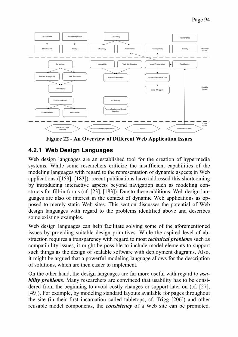
Page 94
4.2.1 Web Design Languages Web design languages are an established tool for the creation of hypermedia systems. While some researchers criticize the insufficient capabilities of the modeling languages with regard to the representation of dynamic aspects in Web applications ([159], [183]), recent publications have addressed this shortcoming by introducing interactive aspects beyond navigation such as modeling con-structs for fill-in forms (cf. [23], [183]). Due to these additions, Web design lan-guages are also of interest in the context of dynamic Web applications as op-posed to merely static Web sites. This section discusses the potential of Web design languages with regard to the problems identified above and describes some existing examples. Web design languages can help facilitate solving some of the aforementioned issues by providing suitable design primitives. While the aspired level of ab-straction requires a transparency with regard to most technical problems such as compatibility issues, it might be possible to include model elements to support such things as the design of scalable software with deployment diagrams. Also, it might be argued that a powerful modeling language allows for the description of solutions, which are then easier to implement. On the other hand, the design languages are far more useful with regard to usa-bility problems. Many researchers are convinced that usability has to be consi-dered from the beginning to avoid costly changes or support later on (cf. [27], [49]). For example, by modeling standard layouts available for pages throughout the site (in their first incarnation called tabletops, cf. Trigg [206]) and other reusable model components, the consistency of a Web site can be promoted.
Lack of State
Flow Control
Compatibility Issues
Testing Reliability Performance
ScalabilityMaintenance
Security TechnicalIssues
Consistency
Internal Homogenity
Predictability
Web Standards
Navigability Web Site Structure
Sense of Orientation
Heterogeneity
Visual Presentation
Support of Intended Task
What-If-Support
Text Design
Internationalization
Standardization Localization
Accessibility
Personalization and Domain Adaption
Ethical and LegalProblems Information ContentAnalysis of User Requirements Credibility
UsabilityIssues
OtherIssues
Figure 22 - An Overview of Different Web Application Issues
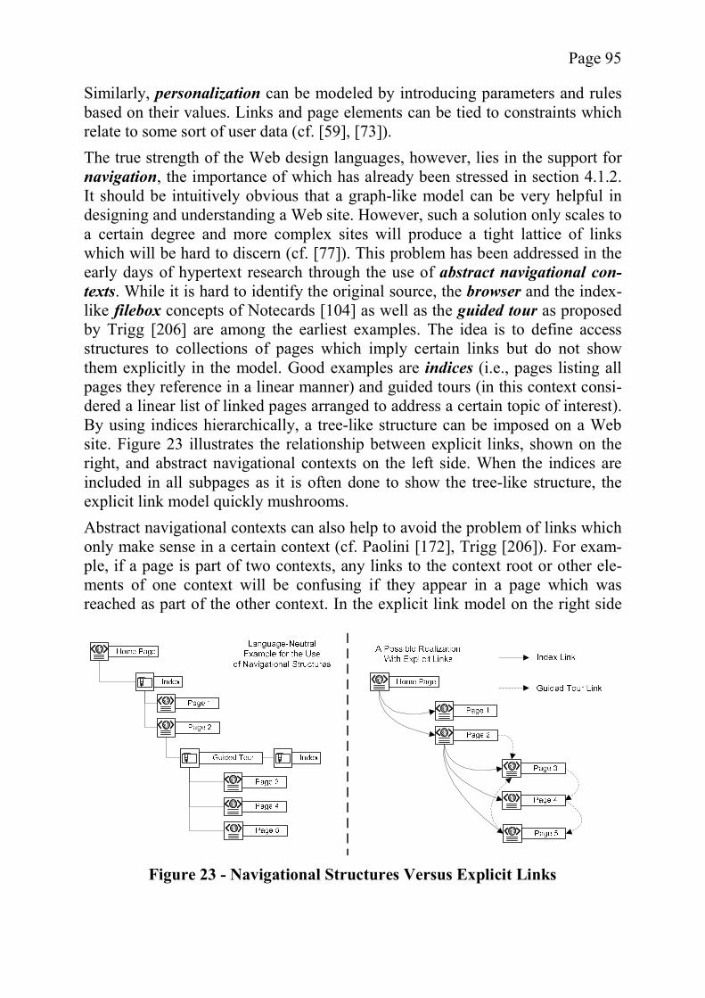
Page 95
Similarly, personalization can be modeled by introducing parameters and rules based on their values. Links and page elements can be tied to constraints which relate to some sort of user data (cf. [59], [73]). The true strength of the Web design languages, however, lies in the support for navigation, the importance of which has already been stressed in section 4.1.2. It should be intuitively obvious that a graph-like model can be very helpful in designing and understanding a Web site. However, such a solution only scales to a certain degree and more complex sites will produce a tight lattice of links which will be hard to discern (cf. [77]). This problem has been addressed in the early days of hypertext research through the use of abstract navigational con-texts. While it is hard to identify the original source, the browser and the index-like filebox concepts of Notecards [104] as well as the guided tour as proposed by Trigg [206] are among the earliest examples. The idea is to define access structures to collections of pages which imply certain links but do not show them explicitly in the model. Good examples are indices (i.e., pages listing all pages they reference in a linear manner) and guided tours (in this context consi-dered a linear list of linked pages arranged to address a certain topic of interest). By using indices hierarchically, a tree-like structure can be imposed on a Web site. Figure 23 illustrates the relationship between explicit links, shown on the right, and abstract navigational contexts on the left side. When the indices are included in all subpages as it is often done to show the tree-like structure, the explicit link model quickly mushrooms. Abstract navigational contexts can also help to avoid the problem of links which only make sense in a certain context (cf. Paolini [172], Trigg [206]). For exam-ple, if a page is part of two contexts, any links to the context root or other ele-ments of one context will be confusing if they appear in a page which was reached as part of the other context. In the explicit link model on the right side
Figure 23 - Navigational Structures Versus Explicit Links
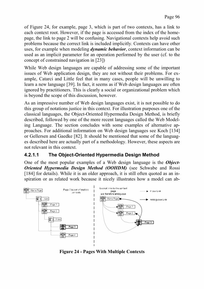
Page 96
of Figure 24, for example, page 3, which is part of two contexts, has a link to each context root. However, if the page is accessed from the index of the home-page, the link to page 2 will be confusing. Navigational contexts help avoid such problems because the correct link is included implicitly. Contexts can have other uses, for example when modeling dynamic behavior, context information can be used as an implicit parameter for an operation performed by the user (cf. to the concept of constrained navigation in [23]) While Web design languages are capable of addressing some of the important issues of Web application design, they are not without their problems. For ex-ample, Catarci and Little feel that in many cases, people will be unwilling to learn a new language [39]. In fact, it seems as if Web design languages are often ignored by practitioners. This is clearly a social or organizational problem which is beyond the scope of this discussion, however. As an impressive number of Web design languages exist, it is not possible to do this group of notations justice in this context. For illustration purposes one of the classical languages, the Object-Oriented Hypermedia Design Method, is briefly described, followed by one of the more recent languages called the Web Model-ing Language. The section concludes with some examples of alternative ap-proaches. For additional information on Web design languages see Koch [134] or Gellersen and Gaedke [82]. It should be mentioned that some of the languag-es described here are actually part of a methodology. However, these aspects are not relevant in this context. 4.2.1.1 The Object-Oriented Hypermedia Design Method One of the most popular examples of a Web design language is the Object-Oriented Hypermedia Design Method (OOHDM) (see Schwabe and Rossi [184] for details). While it is an older approach, it is still often quoted as an in-spiration or as related work because it nicely illustrates how a model can ab-
Figure 24 - Pages With Multiple Contexts
Page 97
stract from the implementation details without requiring additional creative in-put for an implementation. The basis for a hypertext system in OOHDM is the conceptual model, i.e., a UML class diagram describing the data and program logic on which the applica-tion will be based. The associations between the different classes suggest possi-ble but not actual navigational connections. The navigational model plays a central role in OOHDM and can be seen as one of many possible views on the conceptual model. The design primitives are nodes, links, and access structures. A node is a view on or an observer of one or more conceptual classes and has several attributes and link anchors. Links can originate from anchors and are otherwise self-explanatory navigation primitives. Access structures provide a more sophisticated form of navigation, allowing access to sets of links called navigational contexts. The access structures help in avoiding a tight web of individual links in the model. A navigational context is a set of nodes and nested contexts. The nodes con-tained within a context may be defined via an enumeration of its members or via certain properties. For example, a context may be defined to contain all objects of a class, all targets of an n-ary link, or a dynamic set such as the history of pages accessed so far. More complex models are the “class based group”, a con-text that contains (probably disjunctive) subsets of objects of a class, separated according to some criterion, and “link based groups” which follow the same principle for links. The content of a context is considered ordered and is accessi-ble via an access structure, i.e. a collection of implicit links that can take several forms. Typical examples are indices, guided tours, and index guided tours as described above. By defining a separate interface model, the navigational design is kept clean of interface-related concerns. Interface objects effectively mask the navigational constructs, at least from the end users point of view. These objects are based on the concept of Abstract Data Views (ADV) (Cowan [52]). Each ADV can be customized via parameters and can handle certain events (such as a user clicking on a link). It effectively defines the behavior and organization (i.e., layout) of the interface. An ADV may be composed of other ADVs based on the composite pattern (see [75]). The ADV displays the data provided by a navigational node and can follow the links provided by it. The events handled by an ADV can have two main effects. First they can lead to a transition to another node, the typical behavior expected for clicking a link. However, more complex behavior may also be modeled with OOHDM, e.g., changes to the display of the current node. A recent extension to OOHDM, proposed by Schmid and Rossi, enables the modeling of processes in a Web application. The approach is based on entities which store information and business processes with activities. A business process is a special context, which can be considered a statechart diagram and
Page 98
can be left at any point, leading either to a suspension or a restart of the process [183]. 4.2.1.2 The Web Modeling Language Ceri et al. propose a “notation for specifying complex Web sites at a conceptual level” [41] called the Web Modeling Language (WebML), which builds upon the Hypertext Design Model, the Relationship Management Methodology (see 4.2.1.3 for both), OOHDM, and other previous languages. WebML consists of four orthogonal perspectives. The first is the structural model, which describes the data foundation of the site, e.g., as a UML class diagram. Since it basically corresponds to the conceptual model of OOHMD, it need not be addressed further. The most important aspect is the hypertext model which consists of two submo-dels. The composition model defines views on the data called data units, which consist of subsets of the attributes found in classes of the structural model. Other units, such as the index unit or the scroller unit define access structures on spe-cific data units. The units can be grouped in pages. The navigational modellinks the units to provide a logically connected entirety. These links do not only represent the application’s hyperlinks but can also occur between related ele-ments which are within a single page. Contextual links allow one unit to give a context for the other, e.g., the correct index of students can be identified due to a contextual link to a certain class. Non-contextual links ignore the context of the originating unit. There are also shortcuts for certain Web patterns, such as a multi-step index, which is an index pointing to several indices. The presentation model is based on style sheets which can be defined for the pages found in the navigational model. Of greater interest, however, is the per-sonalization model, which is based on a user and group principle. The group information can serve as a basis for business rules and other mechanisms to alter the presentation of the application to the user. Also, due to the separation of structural and navigational model, different views on a site can easily be estab-lished. WebML can be used as a basis for model-driven development of Web applications, as the models can be represented in an XML-based format [41]. 4.2.1.3 Other Web Design Languages Besides the two examples described above, many other Web design languages exist. Due to a large conceptual overlap, these languages are not discussed in detail, for example, the Relationship Management Methodology (RMM) [121] is similar to OOHDM regarding its structure and model elements. For a more detailed discussion of these similarities see Gitzel et al. [88]. One of the earlier examples of a Web modeling language is the Hypertext De-sign Model (HDM). Focusing heavily on a hierarchical definition of the data forming the hypertext application’s foundation, HDM does not offer the differ-ent layers typical for other languages (see sections 4.2.1.1 and 4.2.1.2). Rather it
Page 99
makes many assumptions about the navigational structure of the application by providing implicit links which allow one to navigate the tree of data and switch between the different perspectives of tree leaves called units. An application can consist of several “data trees” called entities, which can be connected by so-called application links and are, in turn, organized by a tree-like structure called an outline, which allows an initial access to the application [77]. An interesting group of Web languages is that of the object-oriented languages. Besides the prominent example of OOHDM described above, there are other examples such as WebComposition [83]. Fröhlich et al. propose a metamodel for hypermedia design which is fairly similar to the other Web design languages of that time and can use a class diagram as a basis for its conceptual model [73]. In contrast to the other languages, the definition of a formal metamodel offers the advantages described in section 3.5.4.1. While an object-oriented approach might initially seem counterintuitive due to the special paradigm of the Web, it becomes more interesting in the light of object-based frameworks (see section 4.2.2). Some languages focus on a particular aspect of usability. For example, the Web Site Design Method (WSDM) is, in the words of its authors, a “’user centered’ rather than ‘data driven’” approach [59] which focuses on personalization using different perspectives on the data, each with a focus on the needs of a particular user. The metamodel proposed by Fröhlich (see above or [73]) also allows for personalization by using a model of user data to design constraints. The dynamic behavior of Web applications as opposed to Web sites is a recent issue which is addressed by some extensions to existing languages (cf. [183]) or new language variants. W2000, for example, proposes to add new kinds of navi-gation, i.e., free and constrained, that identify the data to be used by the opera-tions attached to a link [23].
4.2.2 Web Application Frameworks The Web design languages discussed so far are quite useful for the handling of certain usability issues, especially with regard to navigation, but are unsuitable to address most of the technical problems described in section 4.1.1. This sec-tion examines the potential of Web application frameworks in this regard and describes several existing examples, analyzing to what extent they live up to this potential. Generally speaking, a framework improves the quality of the resulting software by raising the level of abstraction of the solution domain ([102], pp. 60-66). In other words, when solving the problems involved in the creation of new soft-ware based on the framework, the need to address complex details is reduced. Judging by the most popular open-source products, the increase in abstraction provided by Web application frameworks mainly addresses technical issues. For example, by building upon middleware to transparently realize an N-tier archi-
Page 100
tecture, improved security, scalability, and maintainability can be ensured (cf. Offut [159]). In addition, advantages described by practitioners such as Wang encompass automatic validation and transfer of client-side data into objects, the support for cross-browser rendering and internationalization, and the provision of a controller component as the key advantages of Web application frameworks [212]. While the internationalization support mentioned by Wang seems to ad-dress a usability issue, it is typically limited to a mere technical infrastructure for providing several versions of a Web site, for example with resource bundles. Going beyond the actual existing implementations, a mental analysis shows the great potential offered by frameworks with regard to the technical problems identified in section 4.1.1. The introduction of state into the normally stateless HTTP protocol was a major challenge for Web application implementation but can be solved with cookies and the (possibly persistent) server-side storage of user and state information. This approach can be improved by adding a time-out scheme for sessions as well as a clear recovery path (see Kolawa et al. [135], chapter 3). Web application frameworks can encapsulate the technical details and provide complex flow control on a higher level of abstraction. Similarly, the level of abstraction for security can be raised by providing features at a higher level of granularity. Increased abstraction leads to code which is easier to under-stand, in turn making maintenance and to some degree testing easier as well. Web application frameworks can also provide several output modes, possibly transforming the content to provide a format suitable for the various client plat-forms. This way, the compatibility issues can be automatically handled to a large degree. Solutions to scalability, reliability, and performance can also be provided on a general basis. One way is to automatically adapt the output to different band-widths, to provide automatic server-side caching, and to keep down the number of requests to the server. However, the latter is difficult as it is not possible to update parts of HTML pages without resending the entire page, unless Java-Script or a similar technology is used, which introduces other problems ([135], chapter 3). Similarly, support for usability might be imagined but has not yet been a major goal of Web application framework designers. So far, there is only support for some aspects. For example, the consistency of Web sites can be ensured by pro-viding uniform templates or by using composites of subpages to allow the reuse of elements (compare to the concept of tabletops as defined by Trigg [206]). Si-milarly, internationalization is often supported by auxiliaries such as resource bundles. Other features are not necessarily realized yet, despite the suitability of frameworks for these tasks. For example, the navigability of a Web site can be improved by providing a sensible, abstracted navigation scheme, possibly based on the context concept introduced by the Web design languages (cf. [88] or chapter 5) or by providing different views on the same piece of information (cf.
Page 101
Garzotto et al. [79]). The “What-if” support demanded by Nielsen [153], perso-nalization, and accessibility might be implemented as standard modules, en-couraging developers to incorporate these aspects. It is important to note, that even if there is support for these features, this does not mean that the usability of a Web site will necessarily improve. Unlike tech-nical problems which are quite easily measurable, usability issues are less tangi-ble. Even if provided with the right tools, developers will still be able to produce unusable software, especially when the design which serves as a starting point is poor. Additionally, due to the large investment of time into the development of such a framework, it should be designed to be useable for a wide variety of problems; therefore the solutions offered by it must not be too narrow. This view is reflected in the existing examples for Web application frameworks. Despite the fact that Web application frameworks help address quite a few of the quality criteria identified before, it should be noted that the use of frameworks incurs a few general problems. Greenfield et al. feel that it is a non-trivial task to map a specific intended solution to a given framework, which is in effect an unfinished application ([102], pg. 162). Speaking from personal experience, the best explanation for this mismatch is that the developer does not know the exact control flow of the application. Unlike class libraries, which are used as building blocks for a new application, frameworks take the opposite approach, making it difficult to determine the order in which methods are called and whether they are called more than once or not. This, in turn, makes it difficult to decide in which of the methods a variable should be initialized and what state to expect. While a careful documentation can help avoid such problems, it is unrealistic to expect such a support given the nature of open-source framework development. Indeed, Gamma et al. seem to favor a “learning by example” approach for their Eclipse framework, as can be seen in their book (cf. [26]). The great popularity of the Web as a medium of communication has spawned many different frameworks and APIs, which are intended to support the imple-mentation of Web applications. There are many different types of approaches and again only a small subset can be presented in this context. For further in-formation see Wang [212] or the overview presented by the Barracuda project [24]. Many Web application frameworks focus heavily on interactivity, to some ex-tent neglecting the hypermedia paradigm. The well-known framework Apache Struts (cf. [11]), for example, focuses strongly on Web forms and the processes behind them, offering no navigational support for the non-interactive pages of the Web application. Struts’s core concept is the Model 2 architecture, which is a variant of the MVC pattern, and provides a controller that can use various technologies for its model and view. The technological requirements for the model are quite lax, allowing for a wide variety of concepts, including Java Da-tabase Connectivity (JDBC) [200], and EJBs. While originally the choice for
Page 102
view technologies was limited to the somewhat problematic JavaServer Pages (JSP) [180], leading to the proposal of Struts variants such as Struts CX [123] or the Model 2X [143], the recent addition of XSLT [47] and Java ServerFaces (see below) capability has helped to increase the decoupling of data and presentation, the lack of which was criticized by Gitzel et al. [88]. Also, the new Tiles concept for reusable page elements helps to provide more consistency and maintainabili-ty to a Web page. Yet, even though Struts’s focus is on interactivity, Kamm and Klein criticize the concept for storing state in Struts as insufficient for true user dialog. They propose an extension to solve this problem [129]. The Apache Foundation is very active in the field of Web application frame-works, offering several different ones, each with a slightly different focus. Tur-bine [13], for example, provides many services to support the creation of a Web application. These include a simple security service and services for the presen-tation of data using JSPs or Velocity templates (cf. [14]). It also includes a li-mited navigational support which allows using simpler abstract links instead of concrete URLs. Apache Cocoon is a publishing / Web application framework which uses XML and XSLT to prepare data for output. As is it based on a pipe-line principle, several transformations can be performed along with aggregations of different XML sources, all of which can be defined in the so-called sitemap [10]. Other frameworks are intended to provide a simulation of a windows-based graphical user interface. The most well-known example is probably SUN’s Ja-vaServer Faces (JSF) [201]. Other examples include the framework proposed by Puder [175], Echo [147], Jakarta Tapestry [12], and Swinglets [126]. While it is to some extent a question of personal taste, trying to emulate the event-based paradigm of a windows-based GUI with the stateless Web technology can be considered problematic. Despite the arguments in favor, such as improved por-tability and a richer user interface, it is doubtful as to whether or not the poten-tial compatibility problems are worth the benefits. Also, custom GUI compo-nents, which make use of low level events (such as mouse movement), will ei-ther be not supported or result in massive traffic, a problem that Puder admits in his paper [175]. In addition, Nielsen sees pull-down menus in Web applications as a usability problem because they violate the established paradigms (cf. [151], pg. 195). It is reasonable to assume that the same argument can be applied to other non-Web GUI features as well. Besides the general frameworks of the Apache Foundation and the GUI-based approaches, there are many other solutions on the market. Of some interest are the Expresso Framework, which is based on a finite state machine (called Con-troller object) [127], the OONavigator which is based on OOHDM but which is unfortunately not available to the public (cf. [184]), and the academic project called JESSICA [25] by Bartha and Schranz which focuses on content manage-ment.
Page 103
4.3 MDD Approaches to Web Engineering In section 3.5 it was suggested that MDD works best for domain-specific ap-proaches. Given the fact that there are already popular solutions in the field of Web engineering in the form of Web design languages and Web application frameworks, it is important to show how the weaknesses of these existing solu-tions can be remedied with MDD without losing the advantages provided by them. The discussion in this section begins with a short analysis how frameworks and Web design languages can be incorporated into an MDD approach. After that the potential for negating the drawbacks of the conventional techniques is in-spected, leading to a discussion under which circumstances it makes sense to use MDD for Web applications. The section ends with a brief discussion of existing Web-MDD approaches which can be examined in the light of the previous anal-ysis.
4.3.1 Frameworks, Web Design Languages and MDD Since any domain-specific language, and therefore particularly a Web design language, can be considered having a metamodel (see section 3.5), the benefits of using such a design language are also available in the context of MDD. In-deed, many of the Web design languages such as HDM were incorporated into CASE tools back when CASE was the state of the art for automated code gener-ation. In particular, HDM as a basis for code generation is a good example how a degree of freedom is sacrificed to obtain simplicity. The hierarchical data structures of HDM with their implicit links allow to quickly set up things like technical documents but are less suitable when it comes to what Garzotto and Paolini call “’creative’ applications” [77]. Besides these older code generation tools, there is at least one current MDD approach which uses Web design lan-guages as a basis; Fraternali and Paolini use a dialect of HDM in their model-driven Autoweb system [71]. Similarly, frameworks are a natural match for MDD (cf. Völter [209]) as they can help keep the code generation templates simple, moving away from the brute-force code generation approaches of CASE to the more elegant “frame-work completion” suggested by Greenfield et al. ([102], pg. 143). The integra-tion of a framework into an MDD approach does not only add the benefits of frameworks to MDD, it also reduces the typical problems of frameworks, as will be explained in the next section.
4.3.2 The Contribution of MDD to Web Engineering The idea of using code generation for Web applications is not new. Theng for example feels that “[i]f some design ideas could be automated so designers need not worry about their implementation, chances are that better applications could be produced, because designers would be freed to concentrate on their critical
Page 104
issues that cannot be automated” ([204], emphasis added). To make the point further, it is not only “glue code” which should be generated, but code based on rational decisions made by the template designers. Further elaborating this line of thought, it seems possible that model-driven approaches are useful in the con-text of the Web domain. It has already been mentioned that both Web application frameworks and Web design languages can be incorporated into a model-driven approach to Web en-gineering. While the integrated approach combines the advantages of the two conventional approaches, the question remains what kind of additional contribu-tion is made by MDD. This contribution can take the form of an added or ampli-fies benefit or the potential to offset a disadvantage of one of the conventional approaches. One disadvantage which might be reduced by MDD is the lack of detailed in-structions for using the framework. Roberts and Johnson suggest that the “com-positions that represent applications of the framework”, i.e., the application code fragments written for the framework, are “convoluted and difficult to understand and generate”. They instead suggest using code generation based on a model in “standard notations present in the problem domain” to remedy this fault [177]. Since MDD can be based on domain-specific models, it therefore facilitates the use of the framework. There are also several benefits which are not provided by the conventional ap-proaches. In fact, many of the usability problems can be addressed implicitly using MDD. For example the navigation scheme of a Web application can be automatically provided based on general guidelines of a modeler. Of course, a solution at this level of abstraction can only be applied to a small subset of exist-ing problems. Therefore, it should be easy to quickly come up with alternatives or extensions for the code generation templates. A hierarchical approach to MDD as mentioned in chapter 5 might be helpful in this context, due to its unique properties. The constant need for maintenance has been identified as one of the key tech-nical problems of Web applications. While frameworks were identified as help-ful for these tasks, MDD offers an even further improvement. As has been dis-cussed in section 3.1, easier maintenance due to the focus on the model as a cen-tral artifact of the software development process is one of the major strengths of MDD. Clearly, in the Web environment, this potential can be realized to its ful-lest. The heterogeneity of the client side platforms is a major challenge for the de-velopment of universally applicable Web sites. While general platform indepen-dence has been deemed challenging if not impossible in section 3.3.2.1, it is still possible to provide various code generation templates for a small and focused area such as the user interface.
Page 105
The pronounced need for testing resulting from the heterogeneity is supported by the fact that the code generation templates can be tested separately and can benefit from the feedback of all projects using them. Additionally, test cases or simulation runs can be generated automatically. A question of particular interest in the context of this dissertation is, whether Web applications are suitable for a hierarchical segmentation of the problem domain, in order to profit from a hierarchical, domain-specific approach. Sever-al researchers have proposed taxonomies of Web applications (cf. [42], [80]). Ceri et al. identify the categories of commerce, content, service (e.g., Web mail-ing), community, and context (e.g., directories and search engines), believing that these categories are orthogonal and a Web site may combine several of these business models [42]. Ginige and Murugesan identify other types of Web applications, i.e., informational (e.g. online newspapers), interactive (e.g. regis-tration forms), transactional (online shopping), workflow (online planning), col-laborative work environments, online communities and marketplaces, and Web portals [80]. These categories are a good starting point for a hierarchical analysis of the Web application domain, as proposed in chapter 5.
4.3.3 Existing Approaches It seems that in the last few years, the Web was (re-)discovered as a domain which easily lends itself to code generation. For this reason, only a subset of the existing examples can be presented in this context. One category of approaches has been put forward by researchers with an MDD background who would like to illustrate the applicability of their respective approaches to the Web domain. Others come from the field of hypertext design and use the newly aroused inter-est in Web application generation to introduce their code generation approaches to a different audience. The Autoweb System proposed by Fraternali and Paolini belongs to the latter group. It is a model-driven approach for the automatic generation of data inten-sive Web sites. Based on a variant of the Web design language HDM (called HDM-lite), database entries defining the navigational and presentational meta-data are generated along specialized tables for the data described by the concep-tual model. This information is used by a runtime environment to dynamically generate Web pages. The appearance of the Web site is defined via style sheets which are based on presentation elements. These elements can be either built-in ones, configured via parameters, or be black boxes (i.e. code fragments provided by the designer). Legacy systems can easily be integrated using data replication tools [71]. While the approach of Fraternali and Paolini seems to be limited to CMS, it is interesting because its modeling aspects are based on one of the established Web design languages. Overall, AutoWeb’s strength seems to lie in its strong Web background. However, it can only be called model-driven in the sense that it ge-nerates code from models. Many of the requirements defined in section 3.5.1 are
Page 106
not present. For example, there is no mechanism for modular extensions or the interchange of models with other tools. VisualWADE, proposed by Gómez, is another model-driven tool for Web appli-cation development. It is based on a Web design method called OO-H. The tool offers three different design dimensions, structure, navigation, and presentation, each of which consists of a UML diagram, possibly with stereotypes and state-ments in the OCL-derived action language provided by VisualWADE. Pages are abstractly stored as XML files [101]. Again, the tool does not live up to the cri-teria identified for MDD in this dissertation. Heckel and Lohmann propose a model-driven approach for Web applications based on what they call graphical reaction rules. They criticize the lack of dy-namic modeling in most MDD approaches and propose the use of statecharts and collaboration diagrams to describe the dynamic aspects in a fashion similar to that used by Executable UML (cf. [139]). The changes incurred by the state transitions are described by model transformations. One of main problems ad-dressed by the approach is the consistency between the PIM and the platform specific code. By generating a platform independent statechart handler class which encapsulates the business logic, mappings to other technologies are sim-ple and require changes in only a few classes [111]. While the approach has a certain appeal, the use of model transformations as opposed to code in an action language seems to imply too much overhead. Also, the approach does not expli-citly address Web-specific problems and, in fact, could be used for any kind of software domain with little adaptation. Another tool using an executable PSM is Netsilon by Muller et al. Netsilon is designed to avoid changes to the working habits of the graphic designers and HTML integrators, as well as to provide a raised level of abstraction and in-creased productivity. Therefore, care is taken to allow the inclusion of static HTML fragments. The models around which this approach centers belong to three different views (called aspects in the paper), i.e., the business aspect which uses an action language to describe the logic, a hypertext aspect for composition and navigation, and a presentation aspect [142]. Considering the background of some of the authors, Netsilon can be considered an example for Web MDD as a specialization of general MDD. Therefore, the model-driven aspects such as the metamodel and the transformations are stressed, and less attention is given to the Web aspects. For example, the options for navigation seem more primitive than those provided by OOHDM. El Kaim et al. use the Netsilon tool for an agile model-driven approach. In their opinion “Web Engineering should cross-beneficiate from the new OMG MDA initiative and the Agile Modeling concepts and should be supported by suitable tools” ([64], pg. 299). Agile Modeling (AM) is defined by Ambler as “a collec-tion of values, principles, and practices for modeling software that can be ap-plied on a software development project in an effective and lightweight manner”
Page 107
[8]. Because of their informal nature, Ambler considers agile models to be more effective than other models [8]. The core idea of the approach by El Kaim et al. is that model transformations are used to allow the use of agile models as input, thus incorporating the advantage of lightweight models into the model-centricity of MDD approaches. They identify three different aspects in modeling, i.e., a business aspect describing the business model in UML and Xion (an action lan-guage), a presentation aspect, and a navigational aspect. The PSM level is source code, the claim being that the tool generates a 100% of the code [64]. Hera is a model-driven approach to Web information systems (WIS). The paper by Houben et al. emphasizes the information system nature of many modern Web applications, either because of their connection to legacy systems or their data-intensive nature. Hera introduces several views which focus on different aspects of a WIS’s architecture. The semantic layer consists of a conceptual model as well as an integration process that incorporates data from different sources into the model. The application layer describes the application in terms of navigation and user adaptation. The presentation layer specifies the details needed to produce a presentation suitable for a specific platform. The models undergo several transformation steps leading to a platform dependent model (similar to the MDA’s PSM), which is executable within a special Web-based interpreter. Functionality, i.e., business logic, is incorporated via callbacks [116]. The Hera approach is of interest in this context, because it makes heavy use of ontologies and the Resource Description Framework (RDF) [210]. Also, it focuses on data retrieval and manipulation as well as the integration of differ-ent data sources into a unified WIS. Constantine and Lockwood contribute an exotic example in the form of an agile,usage-centered, model-driven approach for Web applications. It is based on a model of the various user roles, abstract, simplified, and technology-free use cases, and abstract prototypes called content models, combined with secondary models of the domain, the business rules, and the working environment. An ab-stract prototype describes the user interface’s contents without actually model-ing the appearance and behavior as well as organizing the content into interac-tion contexts. The focus is on usability and interface design. Of similar impor-tance are the navigational design and the visual and interaction scheme. The lat-ter describes recurring visual elements, common layouts, and templates to apply to the interaction contexts [49]. Their approach is unusual in the field of model-driven development because it does not use any code generation. Still, it is inter-esting to see what kinds of models are considered appropriate. Other examples include WebSA, proposed by Beigbeder and Castro, which uses a UML profile for modeling and which involves an additional PIM-to-PIM transformation [29] or the PIM for Web-based systems proposed by Smith and Shrimpton as a basis for an analysis of model transformations [196]. It is impor-tant to note that none of the examples given here supports a hierarchical ap-
Page 108
proach as described in chapter 5 and that many are either weak with regard to MDD or Web aspects.
4.4 Conclusions In this chapter, the problems unique to the domain of Web applications have been analyzed to assess the potential of MDD in this context. It has been shown that conventional approaches, such as Web design languages and Web applica-tion frameworks, already contribute to the solution of some aspects. MDD can integrate these classical solutions and also contributes additional advantages. The primary contribution is easier maintenance, which is a critical issue in Web applications. Also, the advantages offered by Web design languages are ampli-fied in a model-driven context. Thus, the domain of Web applications is suitable as a basis for an example of a hierarchical MDD approach. While the example will serve mainly as an illustra-tion for the proposed extension mechanism, it should be noted that it neverthe-less contributes to the field of model-driven Web development. In particular, it addresses some aspects missed by existing approaches such as a focus on the typical problems of a dynamic Web application without neglecting the progresses in the field of MDD compared to traditional CASE tools.
Page 109
5 The OMEGA Approach As chapter 3 has shown, a high quality extension mechanism for UML is a key success factor for MDD-based software engineering (see 3.5.1) and it has been argued that concepts like UML Profiles are not sufficient. After a careful analy-sis, it was concluded that hierarchical structures are a promising foundation for a language extension mechanism that supports reuse and therefore reduces the cost of creating new domain-specific code generation modules. As stated in section 1.4, the main scientific contribution of this dissertation is the implementation and evaluation of such a hierarchical extension mechanism. The mechanism, which will be described in the first part of this chapter, is im-plemented using the technological concepts introduced in chapter 2. In particu-lar, it employs a linguistic metamodel based on the design space defined in sec-tion 2.4 and implemented in MOF (see 2.2.2 and 2.3.3). The linguistic metamo-del allows the definition of domain-specific ontological metamodel hierarchies which are stored in XMI format (see 2.2.4) and are manipulated using the JMI-implementation MDR (see 2.2.3). To evaluate the extension mechanism properly, it has to be used for a real-life domain, which is suitable for conventional MDD as described in chapter 3, in order to avoid accidental background factors to interfere with the evaluation. In chapter 4, the domain of Web engineering was identified as well-suited for model-driven development. The Web application domain will be used as the highest layer in an example hierarchy described in the second section. The CMS domain will be used as an example instance. Section 5.3 gives a brief description of the prototypical implementation. The core part of the prototype consists of a domain-independent GUI and the exten-sion mechanism infrastructure. For the purpose of illustration, a Web domain-specific code generator is provided which will be extended for the CMS domain using the extension mechanism and the metamodel layers defined in section 5.2. Employing the prototype, two example application fragments are designed in section 5.4. While the fragments cover the same aspect of a digital library, each of them is based on different requirements, in order to show the flexibility of the domain-specific metamodels. The examples will be used for a critical evalua-tion in the final chapter.
5.1 A Metamodel-Based Extension Mechanism for UML In this section a metamodel-based extension mechanism for UML is described. This mechanism is domain-independent in nature but can be used to define do-main-specific metamodel hierarchies, which can be applied to UML class and statechart diagrams. Figure 25 shows a schematic overview of the elements comprising the extension mechanism (shown in the box on the left) and poten-tially associated elements. The extension mechanism consists of three elements,
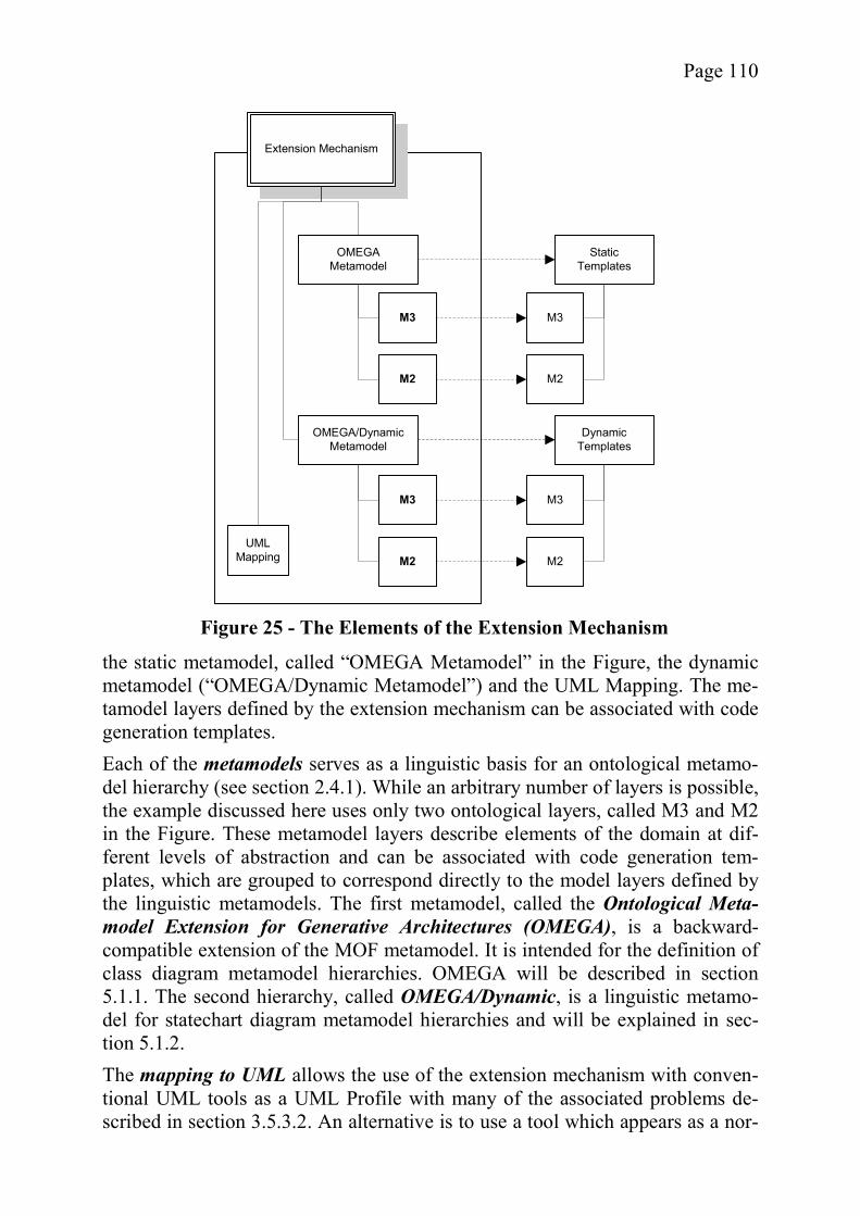
Page 110
the static metamodel, called “OMEGA Metamodel” in the Figure, the dynamic metamodel (“OMEGA/Dynamic Metamodel”) and the UML Mapping. The me-tamodel layers defined by the extension mechanism can be associated with code generation templates. Each of the metamodels serves as a linguistic basis for an ontological metamo-del hierarchy (see section 2.4.1). While an arbitrary number of layers is possible, the example discussed here uses only two ontological layers, called M3 and M2 in the Figure. These metamodel layers describe elements of the domain at dif-ferent levels of abstraction and can be associated with code generation tem-plates, which are grouped to correspond directly to the model layers defined by the linguistic metamodels. The first metamodel, called the Ontological Meta-model Extension for Generative Architectures (OMEGA), is a backward-compatible extension of the MOF metamodel. It is intended for the definition of class diagram metamodel hierarchies. OMEGA will be described in section 5.1.1. The second hierarchy, called OMEGA/Dynamic, is a linguistic metamo-del for statechart diagram metamodel hierarchies and will be explained in sec-tion 5.1.2. The mapping to UML allows the use of the extension mechanism with conven-tional UML tools as a UML Profile with many of the associated problems de-scribed in section 3.5.3.2. An alternative is to use a tool which appears as a nor-
Extension Mechanism
OMEGAMetamodel
OMEGA/Dynamic Metamodel
StaticTemplates
Dynamic Templates
M3
M2
M3
M2
M3
M2
M3
M2UML
Mapping
Figure 25 - The Elements of the Extension Mechanism

Page 111
mal UML tool to the user but is aware of the semantics associated with the mod-el elements. The extension mechanism is designed to address some of the key requirementsfor domain-specific MDD as examined in section 3.5.1. It promotes the use of a single tool for all domains, allows the interchange with other tools, and encou-rages the reuse of existing language elements and mappings. It also addresses one of the major problems identified by critics of the model-driven approach, which is the high initial cost due to the creation of templates (see section 3.3.2.3). The extension mechanism is intended to allow the reuse of templates found at a higher level of abstraction. A detailed examination is not possible be-fore the details of the mechanism have been explained and is thus deferred to section 6.1.3. As has been mentioned, the next two sections describe OMEGA and OMEGA/Dynamic. For readability, the two metamodel hierarchies are described in a non-formal manner and the technical details, which have been already de-scribed elsewhere, are omitted (see [91] or appendix A). To illustrate the diffi-culties associated with the design of an ontological hierarchy, OMEGA is ex-plained in detail. The OMEGA/Dynamic statechart hierarchy is described less extensively, to avoid redundancy. After the description of the two linguistic me-tamodels, the mapping to UML Profiles is explained in section 5.1.3.
5.1.1 The Metamodel for OMEGA Hierarchies This section gives a complete but informal description of OMEGA. Technical details are avoided in order to better convey the ideas behind the design. Figure 26 shows the general structure of the OMEGA linguistic metamodel. OMEGA takes a minimalist approach, extending the MOF hierarchy to allow ontological metamodeling instead of coming up with completely new concepts. The classes in the Figure shown in white are MOF classes which have been changed or are superclasses for the classes newly introduced by OMEGA, which are shown in gray. All other MOF classes have been omitted for brevity but are part of the metamodel. One of the main goals of OMEGA is to keep intrusion minimal and stay as close to the original MOF metamodel as possible. Generally, elements and con-straints are only added as opposed to changed or moved to different places in the metamodel. However, for this reason, some of the new model elements seem less elegant than they could have been. For example, the inheritance hierarchy was not streamlined, as this would imply further changes to the MOF model. Also, for the moment, the possible metamodeling of Operations, which is simi-lar to that of Attributes, is ignored, as it is not needed for the extension mechan-ism.
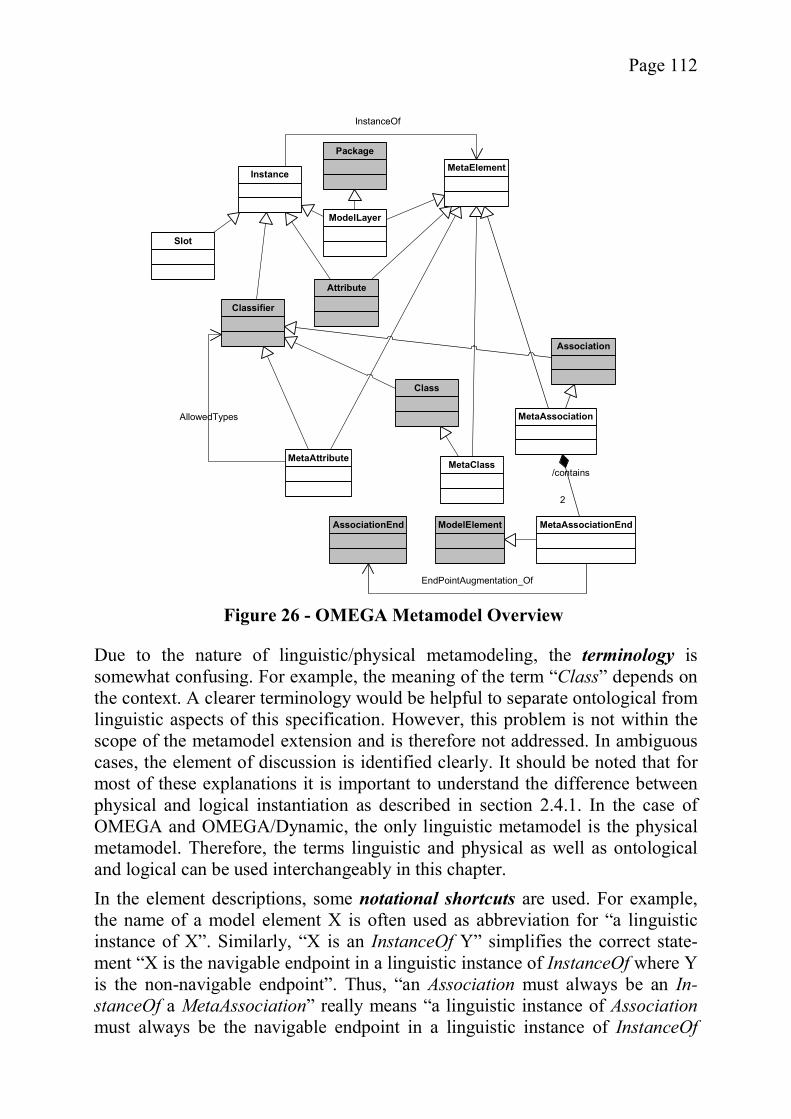
Page 112
Due to the nature of linguistic/physical metamodeling, the terminology is somewhat confusing. For example, the meaning of the term “Class” depends on the context. A clearer terminology would be helpful to separate ontological from linguistic aspects of this specification. However, this problem is not within the scope of the metamodel extension and is therefore not addressed. In ambiguous cases, the element of discussion is identified clearly. It should be noted that for most of these explanations it is important to understand the difference between physical and logical instantiation as described in section 2.4.1. In the case of OMEGA and OMEGA/Dynamic, the only linguistic metamodel is the physical metamodel. Therefore, the terms linguistic and physical as well as ontological and logical can be used interchangeably in this chapter. In the element descriptions, some notational shortcuts are used. For example, the name of a model element X is often used as abbreviation for “a linguistic instance of X”. Similarly, “X is an InstanceOf Y” simplifies the correct state-ment “X is the navigable endpoint in a linguistic instance of InstanceOf where Y is the non-navigable endpoint”. Thus, “an Association must always be an In-stanceOf a MetaAssociation” really means “a linguistic instance of Associationmust always be the navigable endpoint in a linguistic instance of InstanceOf
Classifier
Class
Association
MetaAssociation
MetaClass
MetaElement
MetaAssociationEndAssociationEnd
Package
ModelLayer
InstanceOf
2
/contains
EndPointAugmentation_Of
MetaAttribute
Instance
Attribute
ModelElement
AllowedTypes
Slot
Figure 26 - OMEGA Metamodel Overview
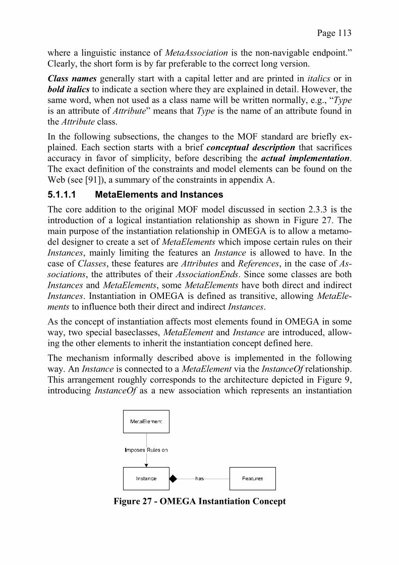
Page 113
where a linguistic instance of MetaAssociation is the non-navigable endpoint.” Clearly, the short form is by far preferable to the correct long version. Class names generally start with a capital letter and are printed in italics or in bold italics to indicate a section where they are explained in detail. However, the same word, when not used as a class name will be written normally, e.g., “Typeis an attribute of Attribute” means that Type is the name of an attribute found in the Attribute class. In the following subsections, the changes to the MOF standard are briefly ex-plained. Each section starts with a brief conceptual description that sacrifices accuracy in favor of simplicity, before describing the actual implementation. The exact definition of the constraints and model elements can be found on the Web (see [91]), a summary of the constraints in appendix A. 5.1.1.1 MetaElements and Instances The core addition to the original MOF model discussed in section 2.3.3 is the introduction of a logical instantiation relationship as shown in Figure 27. The main purpose of the instantiation relationship in OMEGA is to allow a metamo-del designer to create a set of MetaElements which impose certain rules on their Instances, mainly limiting the features an Instance is allowed to have. In the case of Classes, these features are Attributes and References, in the case of As-sociations, the attributes of their AssociationEnds. Since some classes are both Instances and MetaElements, some MetaElements have both direct and indirect Instances. Instantiation in OMEGA is defined as transitive, allowing MetaEle-ments to influence both their direct and indirect Instances. As the concept of instantiation affects most elements found in OMEGA in some way, two special baseclasses, MetaElement and Instance are introduced, allow-ing the other elements to inherit the instantiation concept defined here. The mechanism informally described above is implemented in the following way. An Instance is connected to a MetaElement via the InstanceOf relationship. This arrangement roughly corresponds to the architecture depicted in Figure 9, introducing InstanceOf as a new association which represents an instantiation
Figure 27 - OMEGA Instantiation Concept
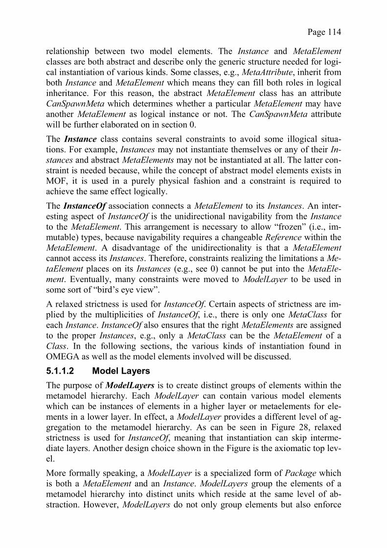
Page 114
relationship between two model elements. The Instance and MetaElementclasses are both abstract and describe only the generic structure needed for logi-cal instantiation of various kinds. Some classes, e.g., MetaAttribute, inherit from both Instance and MetaElement which means they can fill both roles in logical inheritance. For this reason, the abstract MetaElement class has an attribute CanSpawnMeta which determines whether a particular MetaElement may have another MetaElement as logical instance or not. The CanSpawnMeta attribute will be further elaborated on in section 0. The Instance class contains several constraints to avoid some illogical situa-tions. For example, Instances may not instantiate themselves or any of their In-stances and abstract MetaElements may not be instantiated at all. The latter con-straint is needed because, while the concept of abstract model elements exists in MOF, it is used in a purely physical fashion and a constraint is required to achieve the same effect logically. The InstanceOf association connects a MetaElement to its Instances. An inter-esting aspect of InstanceOf is the unidirectional navigability from the Instanceto the MetaElement. This arrangement is necessary to allow “frozen” (i.e., im-mutable) types, because navigability requires a changeable Reference within the MetaElement. A disadvantage of the unidirectionality is that a MetaElementcannot access its Instances. Therefore, constraints realizing the limitations a Me-taElement places on its Instances (e.g., see 0) cannot be put into the MetaEle-ment. Eventually, many constraints were moved to ModelLayer to be used in some sort of “bird’s eye view”. A relaxed strictness is used for InstanceOf. Certain aspects of strictness are im-plied by the multiplicities of InstanceOf, i.e., there is only one MetaClass for each Instance. InstanceOf also ensures that the right MetaElements are assigned to the proper Instances, e.g., only a MetaClass can be the MetaElement of a Class. In the following sections, the various kinds of instantiation found in OMEGA as well as the model elements involved will be discussed. 5.1.1.2 Model Layers The purpose of ModelLayers is to create distinct groups of elements within the metamodel hierarchy. Each ModelLayer can contain various model elements which can be instances of elements in a higher layer or metaelements for ele-ments in a lower layer. In effect, a ModelLayer provides a different level of ag-gregation to the metamodel hierarchy. As can be seen in Figure 28, relaxed strictness is used for InstanceOf, meaning that instantiation can skip interme-diate layers. Another design choice shown in the Figure is the axiomatic top lev-el. More formally speaking, a ModelLayer is a specialized form of Package which is both a MetaElement and an Instance. ModelLayers group the elements of a metamodel hierarchy into distinct units which reside at the same level of ab-straction. However, ModelLayers do not only group elements but also enforce
Page 115
many of the rules implied by the design choices made for the metamodel hie-rarchy. For example, elements are only allowed to instantiate elements from a ModelLayer which is a transitive MetaElement of their own ModelLayer. Also, only top level elements are not required to have a MetaElement. This constraint reflects the design choice to have an axiomatic top level as opposed to a reflex-ive one. A reflexive top level would be far more complex to realize via con-straints and would require more modeling effort on behalf of the OMEGA user with no immediate benefit. It is questionable if the use of recursive top levels makes sense in a logical hierarchy at all except for simulation purposes (e.g., Riehle et al. [176]). Another constraint ensures that ModelLayers only form a single hierarchy, i.e. that there is only one top level layer which is the transitive MetaElement for all other ModelLayers in the instantiation tree. While it is possible to perform MOF’s Package-operations (Import etc.) on ModelLayers, this should be done with caution, especially if the imported Mod-elLayer is used elsewhere in the instantiation hierarchy. In most cases, one con-straint or the other will be violated due to the strict requirements for the instan-tiation hierarchy. These operations have not been ruled out, but they will most likely be useful only to include elements into the top-most layer. The potential of these operations has to be analyzed further. The core motivation for the introduction of ModelLayers is to allow for parts of the model hierarchy to be loaded in a frozen state, providing domain-specific MetaElements for the lower layers. A further motivation is that layers as explicit model elements are preferable to indicating levels by a counter in the model elements as proposed by Atkinson and Kühne [17], mainly because the Model-Layers allow a more natural aggregation of model elements. Figure 29 provides an example for frozen layers (shown in white). An OMEGA user planning to model an online cookbook is bound to load two model layers
Figure 28 - OMEGA Model Layer Concept
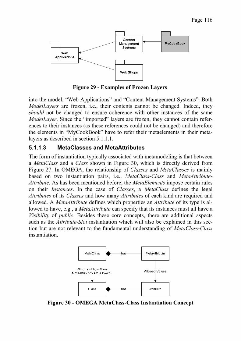
Page 116
into the model; “Web Applications” and “Content Management Systems”. Both ModelLayers are frozen, i.e., their contents cannot be changed. Indeed, they should not be changed to ensure coherence with other instances of the same ModelLayer. Since the “imported” layers are frozen, they cannot contain refer-ences to their instances (as these references could not be changed) and therefore the elements in “MyCookBook” have to refer their metaelements in their meta-layers as described in section 5.1.1.1. 5.1.1.3 MetaClasses and MetaAttributes The form of instantiation typically associated with metamodeling is that between a MetaClass and a Class shown in Figure 30, which is directly derived from Figure 27. In OMEGA, the relationship of Classes and MetaClasses is mainly based on two instantiation pairs, i.e., MetaClass-Class and MetaAttribute-Attribute. As has been mentioned before, the MetaElements impose certain rules on their Instances. In the case of Classes, a MetaClass defines the legal Attributes of its Classes and how many Attributes of each kind are required and allowed. A MetaAttribute defines which properties an Attribute of its type is al-lowed to have, e.g., a MetaAttribute can specify that its instances must all have a Visibility of public. Besides these core concepts, there are additional aspects such as the Attribute-Slot instantiation which will also be explained in this sec-tion but are not relevant to the fundamental understanding of MetaClass-Classinstantiation.
Figure 29 - Examples of Frozen Layers
Figure 30 - OMEGA MetaClass-Class Instantiation Concept
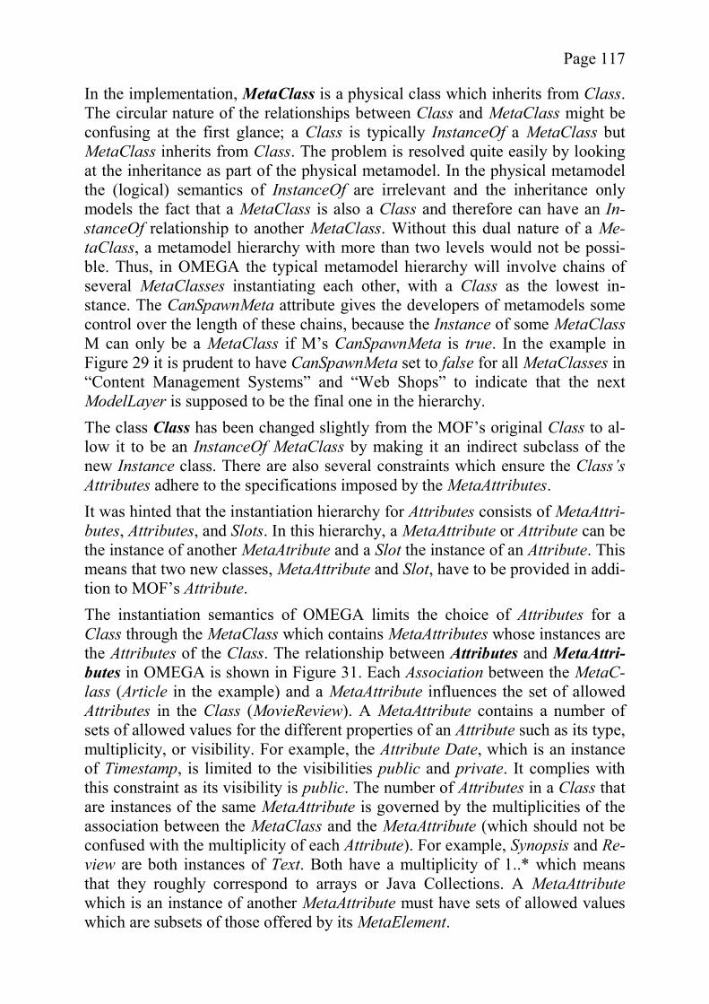
Page 117
In the implementation, MetaClass is a physical class which inherits from Class. The circular nature of the relationships between Class and MetaClass might be confusing at the first glance; a Class is typically InstanceOf a MetaClass but MetaClass inherits from Class. The problem is resolved quite easily by looking at the inheritance as part of the physical metamodel. In the physical metamodel the (logical) semantics of InstanceOf are irrelevant and the inheritance only models the fact that a MetaClass is also a Class and therefore can have an In-stanceOf relationship to another MetaClass. Without this dual nature of a Me-taClass, a metamodel hierarchy with more than two levels would not be possi-ble. Thus, in OMEGA the typical metamodel hierarchy will involve chains of several MetaClasses instantiating each other, with a Class as the lowest in-stance. The CanSpawnMeta attribute gives the developers of metamodels some control over the length of these chains, because the Instance of some MetaClassM can only be a MetaClass if M’s CanSpawnMeta is true. In the example in Figure 29 it is prudent to have CanSpawnMeta set to false for all MetaClasses in “Content Management Systems” and “Web Shops” to indicate that the next ModelLayer is supposed to be the final one in the hierarchy. The class Class has been changed slightly from the MOF’s original Class to al-low it to be an InstanceOf MetaClass by making it an indirect subclass of the new Instance class. There are also several constraints which ensure the Class’s Attributes adhere to the specifications imposed by the MetaAttributes. It was hinted that the instantiation hierarchy for Attributes consists of MetaAttri-butes, Attributes, and Slots. In this hierarchy, a MetaAttribute or Attribute can be the instance of another MetaAtribute and a Slot the instance of an Attribute. This means that two new classes, MetaAttribute and Slot, have to be provided in addi-tion to MOF’s Attribute. The instantiation semantics of OMEGA limits the choice of Attributes for a Class through the MetaClass which contains MetaAttributes whose instances are the Attributes of the Class. The relationship between Attributes and MetaAttri-butes in OMEGA is shown in Figure 31. Each Association between the MetaC-lass (Article in the example) and a MetaAttribute influences the set of allowed Attributes in the Class (MovieReview). A MetaAttribute contains a number of sets of allowed values for the different properties of an Attribute such as its type, multiplicity, or visibility. For example, the Attribute Date, which is an instance of Timestamp, is limited to the visibilities public and private. It complies with this constraint as its visibility is public. The number of Attributes in a Class that are instances of the same MetaAttribute is governed by the multiplicities of the association between the MetaClass and the MetaAttribute (which should not be confused with the multiplicity of each Attribute). For example, Synopsis and Re-view are both instances of Text. Both have a multiplicity of 1..* which means that they roughly correspond to arrays or Java Collections. A MetaAttributewhich is an instance of another MetaAttribute must have sets of allowed values which are subsets of those offered by its MetaElement.

Page 118
The MetaAttribute set for an Attribute’s Type differs slightly from the other sets insofar as the type in MOF is not determined by an attribute but rather by a ref-erence. As strictness forbids associations other than InstanceOf to cross Model-Layer boundaries, it is impossible for an Attribute to reference one of the ele-ments in the list as type, because all these elements are in a higher model layer, i.e. the one where the MetaAttribute is defined. Therefore, the rule in this case is that the type of the Attribute must be an InstanceOf any of the elements in the set of allowed types as specified by the MetaAttributes. The avid reader might immediately identify that this is a problem in the case of PrimitiveTypes which are currently treated as a special case. The inclusion of Slots came relatively late in the development of OMEGA. It addresses a problem which arises when Attributes exist on a ModelLayer other than the lowest one. An example is shown in Figure 32, where Artist has an Attribute called Tools and Painter is an instance of Artist. Intuitively, one might expect the class Painter to have an attribute slot called Tools in a similar fashion to the attribute slot Name. However, in order to include such an attribute slot, the physical metaclass Class would be required to have a corresponding attribute which it of course does not have, being the standard MOF Class. Thus, the new
Figure 31 - MetaAttributes
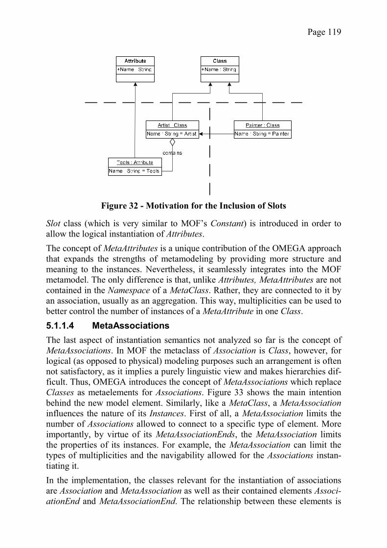
Page 119
Slot class (which is very similar to MOF’s Constant) is introduced in order to allow the logical instantiation of Attributes. The concept of MetaAttributes is a unique contribution of the OMEGA approach that expands the strengths of metamodeling by providing more structure and meaning to the instances. Nevertheless, it seamlessly integrates into the MOF metamodel. The only difference is that, unlike Attributes, MetaAttributes are not contained in the Namespace of a MetaClass. Rather, they are connected to it by an association, usually as an aggregation. This way, multiplicities can be used to better control the number of instances of a MetaAttribute in one Class. 5.1.1.4 MetaAssociations The last aspect of instantiation semantics not analyzed so far is the concept of MetaAssociations. In MOF the metaclass of Association is Class, however, for logical (as opposed to physical) modeling purposes such an arrangement is often not satisfactory, as it implies a purely linguistic view and makes hierarchies dif-ficult. Thus, OMEGA introduces the concept of MetaAssociations which replace Classes as metaelements for Associations. Figure 33 shows the main intention behind the new model element. Similarly, like a MetaClass, a MetaAssociationinfluences the nature of its Instances. First of all, a MetaAssociation limits the number of Associations allowed to connect to a specific type of element. More importantly, by virtue of its MetaAssociationEnds, the MetaAssociation limits the properties of its instances. For example, the MetaAssociation can limit the types of multiplicities and the navigability allowed for the Associations instan-tiating it. In the implementation, the classes relevant for the instantiation of associations are Association and MetaAssociation as well as their contained elements Associ-ationEnd and MetaAssociationEnd. The relationship between these elements is
Figure 32 - Motivation for the Inclusion of Slots
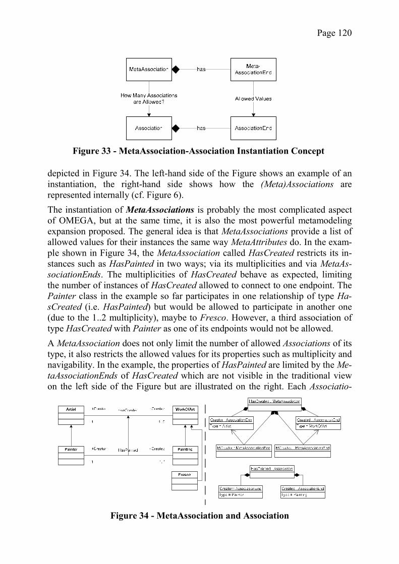
Page 120
depicted in Figure 34. The left-hand side of the Figure shows an example of an instantiation, the right-hand side shows how the (Meta)Associations are represented internally (cf. Figure 6). The instantiation of MetaAssociations is probably the most complicated aspect of OMEGA, but at the same time, it is also the most powerful metamodeling expansion proposed. The general idea is that MetaAssociations provide a list of allowed values for their instances the same way MetaAttributes do. In the exam-ple shown in Figure 34, the MetaAssociation called HasCreated restricts its in-stances such as HasPainted in two ways; via its multiplicities and via MetaAs-sociationEnds. The multiplicities of HasCreated behave as expected, limiting the number of instances of HasCreated allowed to connect to one endpoint. The Painter class in the example so far participates in one relationship of type Ha-sCreated (i.e. HasPainted) but would be allowed to participate in another one (due to the 1..2 multiplicity), maybe to Fresco. However, a third association of type HasCreated with Painter as one of its endpoints would not be allowed. A MetaAssociation does not only limit the number of allowed Associations of its type, it also restricts the allowed values for its properties such as multiplicity and navigability. In the example, the properties of HasPainted are limited by the Me-taAssociationEnds of HasCreated which are not visible in the traditional view on the left side of the Figure but are illustrated on the right. Each Associatio-
Figure 33 - MetaAssociation-Association Instantiation Concept
Figure 34 - MetaAssociation and Association
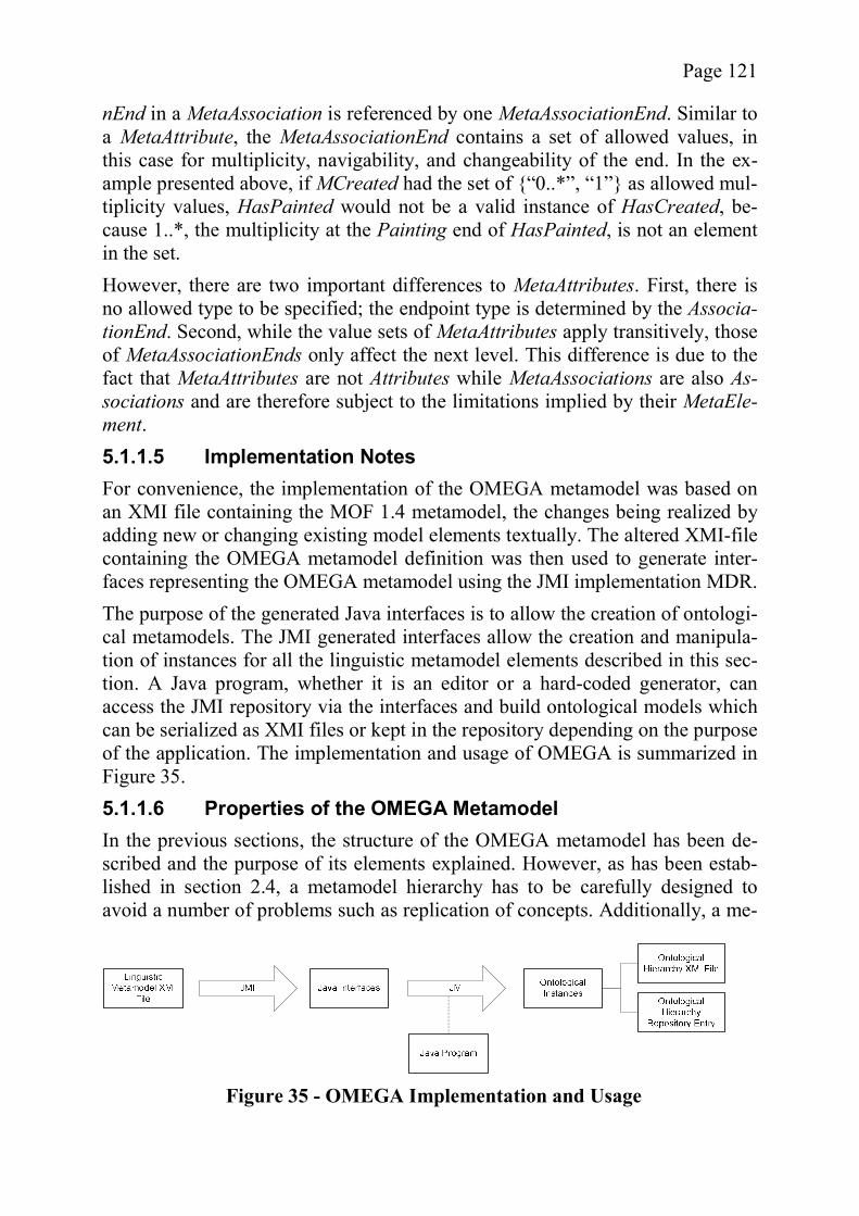
Page 121
nEnd in a MetaAssociation is referenced by one MetaAssociationEnd. Similar to a MetaAttribute, the MetaAssociationEnd contains a set of allowed values, in this case for multiplicity, navigability, and changeability of the end. In the ex-ample presented above, if MCreated had the set of {“0..*”, “1”} as allowed mul-tiplicity values, HasPainted would not be a valid instance of HasCreated, be-cause 1..*, the multiplicity at the Painting end of HasPainted, is not an element in the set. However, there are two important differences to MetaAttributes. First, there is no allowed type to be specified; the endpoint type is determined by the Associa-tionEnd. Second, while the value sets of MetaAttributes apply transitively, those of MetaAssociationEnds only affect the next level. This difference is due to the fact that MetaAttributes are not Attributes while MetaAssociations are also As-sociations and are therefore subject to the limitations implied by their MetaEle-ment. 5.1.1.5 Implementation Notes For convenience, the implementation of the OMEGA metamodel was based on an XMI file containing the MOF 1.4 metamodel, the changes being realized by adding new or changing existing model elements textually. The altered XMI-file containing the OMEGA metamodel definition was then used to generate inter-faces representing the OMEGA metamodel using the JMI implementation MDR. The purpose of the generated Java interfaces is to allow the creation of ontologi-cal metamodels. The JMI generated interfaces allow the creation and manipula-tion of instances for all the linguistic metamodel elements described in this sec-tion. A Java program, whether it is an editor or a hard-coded generator, can access the JMI repository via the interfaces and build ontological models which can be serialized as XMI files or kept in the repository depending on the purpose of the application. The implementation and usage of OMEGA is summarized in Figure 35. 5.1.1.6 Properties of the OMEGA Metamodel In the previous sections, the structure of the OMEGA metamodel has been de-scribed and the purpose of its elements explained. However, as has been estab-lished in section 2.4, a metamodel hierarchy has to be carefully designed to avoid a number of problems such as replication of concepts. Additionally, a me-
Figure 35 - OMEGA Implementation and Usage
Page 122
tamodel can cause other difficulties and it should be mentioned that OMEGA quite literally inherits some problems from MOF. Thus, to establish the proper-ties of OMEGA, the linguistic metamodel is compared to the design space for metamodel hierarchies before discussing its problems and open questions. In the light of the design space defined for metamodel hierarchies, the static OMEGA metamodel can be classified as a nonlinear hierarchy with an arbitrary number of ontological layers, an implicit real-world layer, and an axiomatic top level. It uses a relaxed strictness and a transitive InstanceOf relationship, which was considered one aspect of deep instantiation. The instantiation semantics are uniform and the linguistic model is fairly detailed. One advantage of these design decisions is that the complexity of the resulting model is kept relatively low. The relaxed strictness might increase the perceived complexity, but solely for those who are unfamiliar with the concept. The con-sistency and precision is improved by the use of nonlinearity and deep instantia-tion. As Table 1 shows, there are few choices which have a great positive effect on robustness to change and expressional strength, and consequently the choices merely minimize potential problems in this respect. The most important of all criteria, however, is the extensibility; after all, the hierarchy is intended to serve as an extension mechanism. Thus all choices were made in favor of exten-sibility, unless they would lead to unacceptable results with regard to the other criteria. For example, not using any strictness would have improved extensibility further but at the price of an unacceptable reduction of precision and expression-al strength. However, while the OMEGA metamodel scores high in the criteria defined for good metamodel hierarchies, it has several limitations which are either open work or were accepted in order to keep the changes to MOF minimal. Since it is important to be aware of these limitations and to understand why they exist, each of them will be addressed briefly. One case where the original definition of MOF prevents an elegant solution is abstract classes. For some reasons, the designers of the MOF metamodel chose to make the attribute IsAbstract a feature of GeneralizableElement. While there is a connection between the two concepts, after all abstract classes only make sense if some other class inherits from them, this choice is unfortunate. The rea-son is, that the compliance to abstraction is a constraint, which is best enforced in the model element Instance. The most straightforward approach would have been to include the attribute IsAbstract in MetaElement and deny Instances the right to connect to MetaElements where the attribute value is true. While a simi-lar constraint has been implemented, it is less elegant as it has to perform a type check to see whether the MetaElement is also a GeneralizableElement. Another limitation of OMEGA is the lack of navigability from MetaElements to their instances via the InstanceOf association. The reason for this limitation is that the ontological metamodel layers are typically immutable as described
Page 123
above. Since navigability requires a reference in the Class instance and such a reference cannot be changed in a frozen model element, there is no such naviga-bility. A drawback of this arrangement is that the linguistic types of metaclasses cannot define any constraints which affect the classes’ ontological instances. In the case of the prototype’s hierarchy, this was not a problem, but it remains to be seen how well the system fares in the general case, possibly mandating an “un-freezing” of the metalayers. The lack of support for metaoperations (i.e., behavioral features) of any kind might strike some as problematic. However, as has been mentioned before, there are some arguments in favor of leaving out metaoperations because they are not needed. Still, for the sake of completeness, it might be useful to include metao-perations in a future version of OMEGA. Finally, the encoding of values in Slots as character strings as opposed to the adequate primitive type is unsatisfactory. The encoding is also incomplete, be-cause custom defined and complex types cannot be handled easily as character strings. However, the choice for value representation mirrors exactly the one used for Constants in the MOF standard and was adopted for consistency. There are several open questions which will have to be addressed in future work. While OMEGA aims at being a complete metamodel for ontological me-tamodeling, several questions are left for future revisions of this metamodel ex-tension. One important question is whether inheritance should be restricted with regard to metaclasses, i.e., is it acceptable if a class inherits from another class which does not have the same metaclass? Concepts such as powertypes [157] can be brought forth as arguments to allow cross-type inheritance. On the other hand, with the instantiation semantics chosen for OMEGA, it is questionable whether cross-class inheritance is possible at all, because the attributes a class may have depend on its metaclass. Thus, if a class inherits an attribute from a class of a different type, it is possible that a constraint violation occurs. Also, cross-type inheritance might in some respects be considered a violation of strictness as it enabled a class (indirectly) to have more than one metaclass. If one is to accept this violation, the question remains how to consolidate the constraints imposed on the multiple metaclasses. Most likely, the valid attributes would be the union of all attributes. Still, there are some problems in the details similar to those found with multiple inheritance. Another question, which concerns instantiation semantics as much as strictness, is whether metaelements should be allowed to dominate multiple layers instead of only the next one. For example, it might be useful if a MetaAssociation be-tween an entity and a (single) key has the power to ensure that all layers will al-ways have the proper multiplicity. Rudimentary aspects of such a multi-layer dominance can be found in the instantiation semantics of MetaAttributes, as each consecutive MetaAttribute can only allow a subset of the values allowed by
Page 124
the MetaAttribute it instantiates. On the one hand, more control by the MetaLay-ers makes it easier to generate code but, on the other hand, there is the danger of the metamodel becoming too complex or inflexible. Since OMEGA’s primary application is code generation, it is important to con-sider the modeling of legacy systems. Clearly, it should be possible to include some existing software or classes into the models created with OMEGA. How-ever, the question as of how to implement this extension is not so easily ans-wered. Is it preferable to have a special model element which acts as a tag to mark classes which already exist? Or should such decisions be made at a tem-plate level, possibly as input parameters? Each of the two approaches has its own merits and there are probably many more one could come up with. The last open question is that of the modeling of primitive types. It has already been mentioned that the typing of attributes is not so straightforward with regard to primitive types, as they are neither MetaElement nor Instance. A possible so-lution might be to have an “invariant” ModelLayer containing self-instantiating elements such as primitive types or to disallow primitive types altogether, only employing domain-specific types as is encouraged in the Executable UML ap-proach by Mellor and Balcer. Despite these shortcomings and open questions, the OMEGA metamodel is fully functional and can be used as a basis for a hierarchical description of a domain-specific application as will be illustrated in section 5.2. The elements of the stat-ic model are complemented by the dynamic metamodel hierarchy OMEGA/Dynamic which will be described next.
5.1.2 The Metamodel for OMEGA/Dynamic Hierarchies It has already been mentioned that a hierarchy for statecharts is needed to com-plement the static hierarchy just described. The OMEGA/Dynamic linguistic metamodel described in this section fills this role. It is interesting to note that there is no example of a dynamic ontological hierarchy in the literature, al-though other extension mechanisms such as inheritance have been proposed for statecharts (e.g., [181]). Initial experiments quickly led to the conclusion that the traditional notion of instantiation makes little sense for dynamic metamodels. Nevertheless, the dynamic part of a software artifact can profit even more from a hierarchical extension mechanism than the static one as will be shown in the ex-ample (see section 5.2). The linguistic metamodel is particularly interesting be-cause it stretches the boundaries of the concept of a metamodel hierarchy estab-lished in this dissertation. Nevertheless, it is still within the design space defined above (see section 5.1.2.5).

Page 125
Functionally, OMEGA/Dynamic can be seen as subservient to the OMEGA hie-rarchy (as shown in Figure 36). The purpose of the OMEGA/Dynamic hierarchy is to provide the infrastructure for defining the behavior associated with the OMEGA M1 level elements. Using its metaelements, the OMEGA/Dynamic hierarchy allows the definition of statechart diagrams at the M1 level. The con-nection between the classes of OMEGA M1 and the statecharts of OMEGA/Dynamic M1 is established via a mapping that is not part of the model definition. The description of OMEGA/Dynamic follows the same general pattern as that of OMEGA. After the initial descriptive overview, the vital model elements are described. Afterwards, the quality of the linguistic metamodel is evaluated and design choices and open questions are addressed. The elements of the OMEGA/Dynamic metamodel are shown in Figure 37 us-ing the MOF notation. Since it is not an extension of the MOF metamodel, there are no existing classes to be considered; in fact, all elements of the OMEGA/Dynamic metamodel are shown in the Figure. As can be seen, some of the elements found in the OMEGA metamodel are also present here, i.e., the In-stance and MetaElement pair and the ModelLayer. These elements represent the basic concepts of ontological metamodeling which are needed in a similar way in both hierarchies. The most important elements in the metamodel are the Me-taStateCharts and StateCharts as well as the different kinds of MetaStates and States. There are also some elements which the reader might miss at this point, in particular MetaTransitions and Signals.
M1A
M1B
M3
M2
M1M1
OMEGA OMEGA/Dynamic
M3
M2
Figure 36 - OMEGA/Dynamic and OMEGA
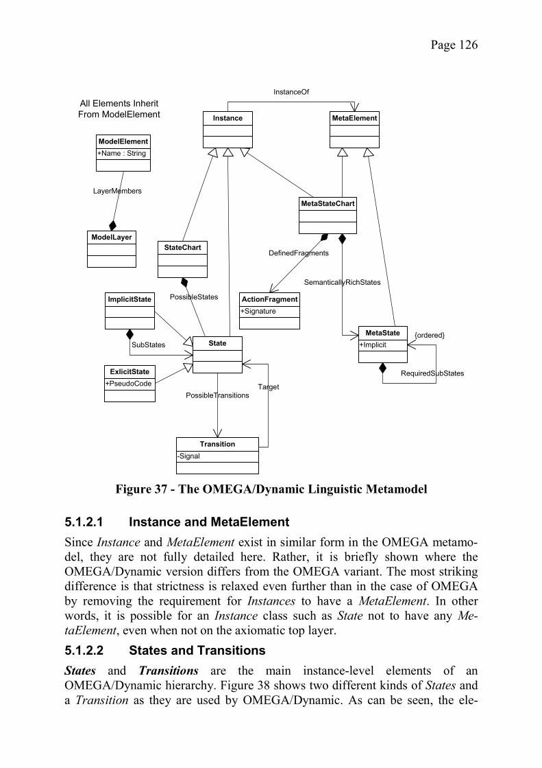
Page 126
5.1.2.1 Instance and MetaElement Since Instance and MetaElement exist in similar form in the OMEGA metamo-del, they are not fully detailed here. Rather, it is briefly shown where the OMEGA/Dynamic version differs from the OMEGA variant. The most striking difference is that strictness is relaxed even further than in the case of OMEGA by removing the requirement for Instances to have a MetaElement. In other words, it is possible for an Instance class such as State not to have any Me-taElement, even when not on the axiomatic top layer. 5.1.2.2 States and Transitions States and Transitions are the main instance-level elements of an OMEGA/Dynamic hierarchy. Figure 38 shows two different kinds of States and a Transition as they are used by OMEGA/Dynamic. As can be seen, the ele-
MetaElementInstance
InstanceOf
MetaStateChart
+SignatureActionFragment
DefinedFragmentsStateChart
State
PossibleStates
SemanticallyRichStates
+ImplicitMetaState
+PseudoCodeExlicitState
ImplicitState
RequiredSubStates
SubStates
-SignalTransition
PossibleTransitionsTarget
+Name : StringModelElement
All Elements InheritFrom ModelElement
{ordered}
ModelLayer
LayerMembers
Figure 37 - The OMEGA/Dynamic Linguistic Metamodel
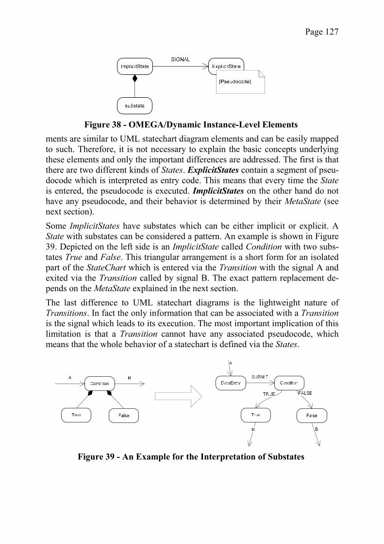
Page 127
ments are similar to UML statechart diagram elements and can be easily mapped to such. Therefore, it is not necessary to explain the basic concepts underlying these elements and only the important differences are addressed. The first is that there are two different kinds of States. ExplicitStates contain a segment of pseu-docode which is interpreted as entry code. This means that every time the Stateis entered, the pseudocode is executed. ImplicitStates on the other hand do not have any pseudocode, and their behavior is determined by their MetaState (see next section). Some ImplicitStates have substates which can be either implicit or explicit. A State with substates can be considered a pattern. An example is shown in Figure 39. Depicted on the left side is an ImplicitState called Condition with two subs-tates True and False. This triangular arrangement is a short form for an isolated part of the StateChart which is entered via the Transition with the signal A and exited via the Transition called by signal B. The exact pattern replacement de-pends on the MetaState explained in the next section. The last difference to UML statechart diagrams is the lightweight nature of Transitions. In fact the only information that can be associated with a Transitionis the signal which leads to its execution. The most important implication of this limitation is that a Transition cannot have any associated pseudocode, which means that the whole behavior of a statechart is defined via the States.
Figure 38 - OMEGA/Dynamic Instance-Level Elements
Figure 39 - An Example for the Interpretation of Substates
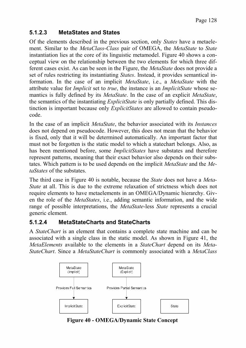
Page 128
5.1.2.3 MetaStates and States Of the elements described in the previous section, only States have a metaele-ment. Similar to the MetaClass-Class pair of OMEGA, the MetaState to Stateinstantiation lies at the core of its linguistic metamodel. Figure 40 shows a con-ceptual view on the relationship between the two elements for which three dif-ferent cases exist. As can be seen in the Figure, the MetaState does not provide a set of rules restricting its instantiating States. Instead, it provides semantical in-formation. In the case of an implicit MetaState, i.e., a MetaState with the attribute value for Implicit set to true, the instance is an ImplicitState whose se-mantics is fully defined by its MetaState. In the case of an explicit MetaState, the semantics of the instantiating ExplicitState is only partially defined. This dis-tinction is important because only ExplicitStates are allowed to contain pseudo-code. In the case of an implicit MetaState, the behavior associated with its Instancesdoes not depend on pseudocode. However, this does not mean that the behavior is fixed, only that it will be determined automatically. An important factor that must not be forgotten is the static model to which a statechart belongs. Also, as has been mentioned before, some ImplicitStates have substates and therefore represent patterns, meaning that their exact behavior also depends on their subs-tates. Which pattern is to be used depends on the implicit MetaState and the Me-taStates of the substates. The third case in Figure 40 is notable, because the State does not have a Meta-State at all. This is due to the extreme relaxation of strictness which does not require elements to have metaelements in an OMEGA/Dynamic hierarchy. Giv-en the role of the MetaStates, i.e., adding semantic information, and the wide range of possible interpretations, the MetaState-less State represents a crucial generic element. 5.1.2.4 MetaStateCharts and StateCharts A StateChart is an element that contains a complete state machine and can be associated with a single class in the static model. As shown in Figure 41, the MetaElements available to the elements in a StateChart depend on its Meta-StateChart. Since a MetaStateChart is commonly associated with a MetaClass
Figure 40 - OMEGA/Dynamic State Concept

Page 129
in the static model, it can be used to provide a “toolbox” which contains ele-ments that are suitable to model the behavior typically expected by the corres-ponding static model element. Besides MetaStates, a MetaStateChart can also contain ActionFragments. The ActionFragments represent a kind of “helper methods” which can be used in the pseudocode of ExplicitStates. In this prototypical version of OMEGA/Dynamic, the signature of a fragment is defined as text only. It is interesting to note that the ActionFragments have no MetaElement and do not form a hierarchy. Rather each MetaStateChart adds additional ActionFragments, which provide the end user with a set of elements covering all levels of abstraction. 5.1.2.5 Properties of the OMEGA/Dynamic Metamodel In parallel to the discussion of the OMEGA metamodel, the description of OMEGA/Dynamic ends with a short analysis of its properties, again first using the metamodel hierarchy design space and then addressing other issues and open work. At the first glance, the OMEGA/Dynamic hierarchy appears to be rather differ-ent from other metamodel hierarchies and does not seem to correspond to the design space defined in section 2.4. The reason is that it exhibits a very special form of relaxed strictness. Besides the relaxation suggested for class diagram hierarchies (see section 2.4.4), the requirement that a class needs to have a me-taclass unless it is at the topmost level is also removed. It is interesting to see how such a minor change affects the appearance of the hierarchy. Using the variables defined for the design space, the OMEGA/Dynamic hie-rarchy can be described as a nonlinear hierarchy with deep instantiation, relaxed strictness, axiomatic top level, implicit real world level, and uniform instantia-tion semantics. Its number of layers is arbitrary and the linguistic metamodel has a wide scope. Thus, from the standpoint of the design space, it is the same kind of metamodel hierarchy as the static one and the reasoning given in section 5.1.1.6 also applies to it.
Figure 41 - OMEGA/Dynamic StateChart Concept
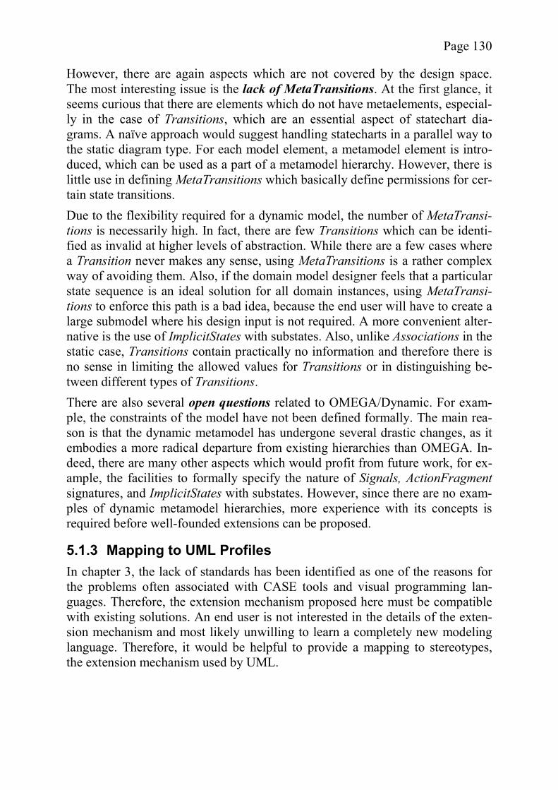
Page 130
However, there are again aspects which are not covered by the design space. The most interesting issue is the lack of MetaTransitions. At the first glance, it seems curious that there are elements which do not have metaelements, especial-ly in the case of Transitions, which are an essential aspect of statechart dia-grams. A naïve approach would suggest handling statecharts in a parallel way to the static diagram type. For each model element, a metamodel element is intro-duced, which can be used as a part of a metamodel hierarchy. However, there is little use in defining MetaTransitions which basically define permissions for cer-tain state transitions. Due to the flexibility required for a dynamic model, the number of MetaTransi-tions is necessarily high. In fact, there are few Transitions which can be identi-fied as invalid at higher levels of abstraction. While there are a few cases where a Transition never makes any sense, using MetaTransitions is a rather complex way of avoiding them. Also, if the domain model designer feels that a particular state sequence is an ideal solution for all domain instances, using MetaTransi-tions to enforce this path is a bad idea, because the end user will have to create a large submodel where his design input is not required. A more convenient alter-native is the use of ImplicitStates with substates. Also, unlike Associations in the static case, Transitions contain practically no information and therefore there is no sense in limiting the allowed values for Transitions or in distinguishing be-tween different types of Transitions. There are also several open questions related to OMEGA/Dynamic. For exam-ple, the constraints of the model have not been defined formally. The main rea-son is that the dynamic metamodel has undergone several drastic changes, as it embodies a more radical departure from existing hierarchies than OMEGA. In-deed, there are many other aspects which would profit from future work, for ex-ample, the facilities to formally specify the nature of Signals, ActionFragmentsignatures, and ImplicitStates with substates. However, since there are no exam-ples of dynamic metamodel hierarchies, more experience with its concepts is required before well-founded extensions can be proposed.
5.1.3 Mapping to UML Profiles In chapter 3, the lack of standards has been identified as one of the reasons for the problems often associated with CASE tools and visual programming lan-guages. Therefore, the extension mechanism proposed here must be compatible with existing solutions. An end user is not interested in the details of the exten-sion mechanism and most likely unwilling to learn a completely new modeling language. Therefore, it would be helpful to provide a mapping to stereotypes, the extension mechanism used by UML.
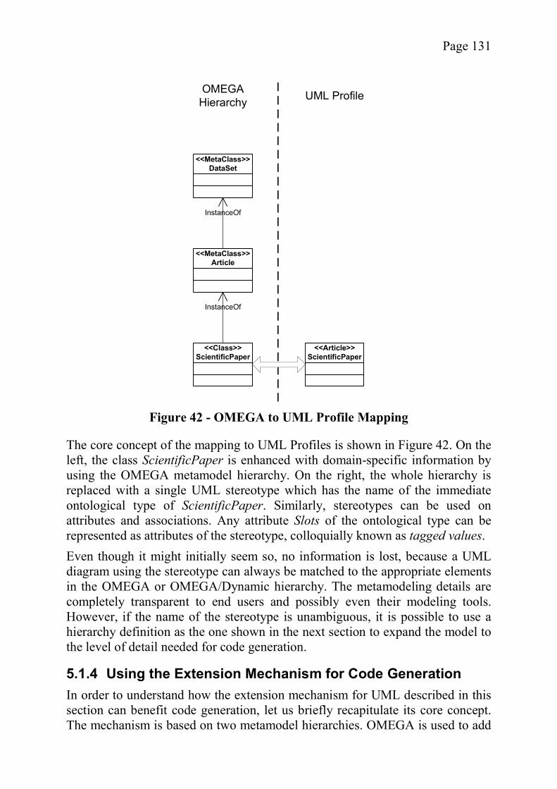
Page 131
The core concept of the mapping to UML Profiles is shown in Figure 42. On the left, the class ScientificPaper is enhanced with domain-specific information by using the OMEGA metamodel hierarchy. On the right, the whole hierarchy is replaced with a single UML stereotype which has the name of the immediate ontological type of ScientificPaper. Similarly, stereotypes can be used on attributes and associations. Any attribute Slots of the ontological type can be represented as attributes of the stereotype, colloquially known as tagged values. Even though it might initially seem so, no information is lost, because a UML diagram using the stereotype can always be matched to the appropriate elements in the OMEGA or OMEGA/Dynamic hierarchy. The metamodeling details are completely transparent to end users and possibly even their modeling tools. However, if the name of the stereotype is unambiguous, it is possible to use a hierarchy definition as the one shown in the next section to expand the model to the level of detail needed for code generation.
5.1.4 Using the Extension Mechanism for Code Generation In order to understand how the extension mechanism for UML described in this section can benefit code generation, let us briefly recapitulate its core concept. The mechanism is based on two metamodel hierarchies. OMEGA is used to add
<<MetaClass>>DataSet
<<MetaClass>>Article
<<Class>>ScientificPaper
InstanceOf
InstanceOf
OMEGAHierarchy UML Profile
<<Article>>ScientificPaper
Figure 42 - OMEGA to UML Profile Mapping

Page 132
domain-specific, hierarchically arranged information to class diagrams, while OMEGA/Dynamic does the same for statecharts. Similarly to Executable UML, the statechart diagrams are associated with those classes of the model that dis-play complex behavior. A code generation tool can use the additional information provided by the me-taelements to pick the right kinds of code templates, add or remove classes from the design model, and generate documentation among other things. In order to be able to better describe how these improvements become possible, an example hierarchy is presented in the next section and is used in the context of a proto-type described in section 5.3.
5.2 A Metamodel Hierarchy for MDD In this section, an ontological metamodel hierarchy is described which uses the linguistic metamodels of the extension mechanism introduced in section 5.1. The metamodel hierarchy will not only help to understand the practical applica-bility of the extension mechanism but will also serve as a basis for the evalua-tion of the prototype detailed in section 5.3. Figure 43 shows the example hierarchy used for the remainder of this chapter. At the M3 level is a metamodel for Web applications. This technology-oriented but platform independent metamodel is used as a basis for the creation of meta-models specific to a particular business domain. There are many possibilities for M2 metamodels and the ones shown are only examples. As a proof of concept the domain of Content Management has been prototypically implemented. The models, representing individual software projects in the M2 domain, can be found at the lowest level of the hierarchy. M1 is the only level that an end-user of a domain-specific extension needs to manipulate.
Figure 43 - An Example Metamodel Hierarchy for OMEGA
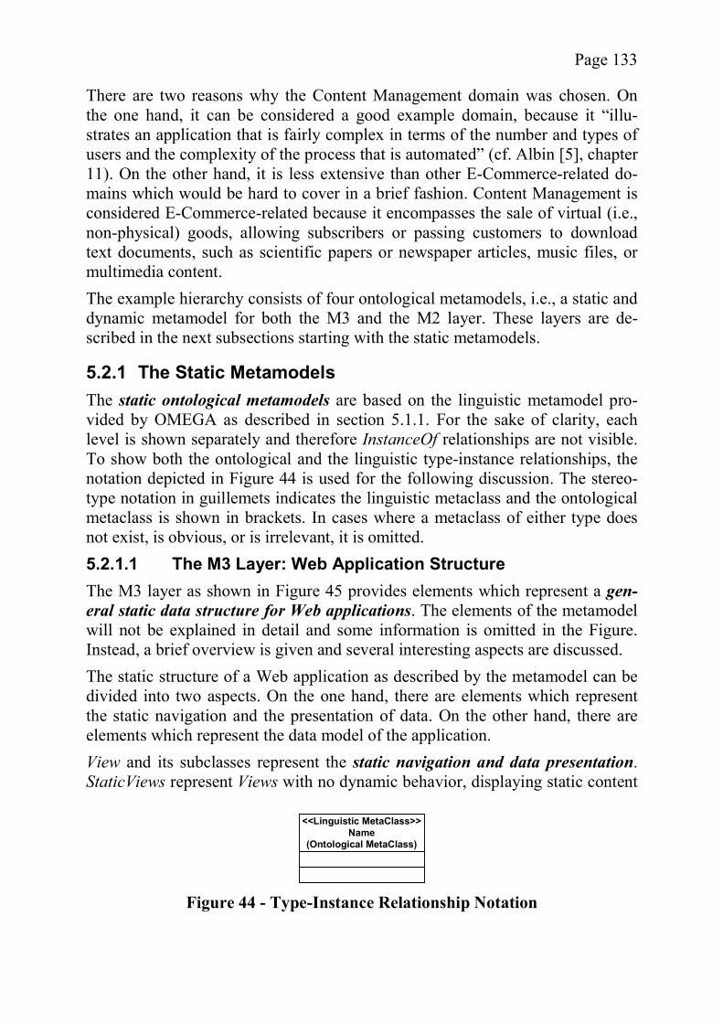
Page 133
There are two reasons why the Content Management domain was chosen. On the one hand, it can be considered a good example domain, because it “illu-strates an application that is fairly complex in terms of the number and types of users and the complexity of the process that is automated” (cf. Albin [5], chapter 11). On the other hand, it is less extensive than other E-Commerce-related do-mains which would be hard to cover in a brief fashion. Content Management is considered E-Commerce-related because it encompasses the sale of virtual (i.e., non-physical) goods, allowing subscribers or passing customers to download text documents, such as scientific papers or newspaper articles, music files, or multimedia content. The example hierarchy consists of four ontological metamodels, i.e., a static and dynamic metamodel for both the M3 and the M2 layer. These layers are de-scribed in the next subsections starting with the static metamodels.
5.2.1 The Static Metamodels The static ontological metamodels are based on the linguistic metamodel pro-vided by OMEGA as described in section 5.1.1. For the sake of clarity, each level is shown separately and therefore InstanceOf relationships are not visible. To show both the ontological and the linguistic type-instance relationships, the notation depicted in Figure 44 is used for the following discussion. The stereo-type notation in guillemets indicates the linguistic metaclass and the ontological metaclass is shown in brackets. In cases where a metaclass of either type does not exist, is obvious, or is irrelevant, it is omitted. 5.2.1.1 The M3 Layer: Web Application Structure The M3 layer as shown in Figure 45 provides elements which represent a gen-eral static data structure for Web applications. The elements of the metamodel will not be explained in detail and some information is omitted in the Figure. Instead, a brief overview is given and several interesting aspects are discussed. The static structure of a Web application as described by the metamodel can be divided into two aspects. On the one hand, there are elements which represent the static navigation and the presentation of data. On the other hand, there are elements which represent the data model of the application. View and its subclasses represent the static navigation and data presentation. StaticViews represent Views with no dynamic behavior, displaying static content
<<Linguistic MetaClass>>Name
(Ontological MetaClass)
Figure 44 - Type-Instance Relationship Notation
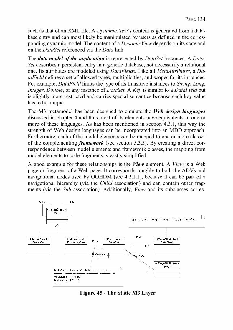
Page 134
such as that of an XML file. A DynamicView’s content is generated from a data-base entry and can most likely be manipulated by users as defined in the corres-ponding dynamic model. The content of a DynamicView depends on its state and on the DataSet referenced via the Data link. The data model of the application is represented by DataSet instances. A Data-Set describes a persistent entry in a generic database, not necessarily a relational one. Its attributes are modeled using DataFields. Like all MetaAttributes, a Da-taField defines a set of allowed types, multiplicities, and scopes for its instances. For example, DataField limits the type of its transitive instances to String, Long, Integer, Double, or any instance of DataSet. A Key is similar to a DataField but is slightly more restricted and carries special semantics because each key value has to be unique. The M3 metamodel has been designed to emulate the Web design languagesdiscussed in chapter 4 and thus most of its elements have equivalents in one or more of these languages. As has been mentioned in section 4.3.1, this way the strength of Web design languages can be incorporated into an MDD approach. Furthermore, each of the model elements can be mapped to one or more classes of the complementing framework (see section 5.3.5). By creating a direct cor-respondence between model elements and framework classes, the mapping from model elements to code fragments is vastly simplified. A good example for these relationships is the View element. A View is a Web page or fragment of a Web page. It corresponds roughly to both the ADVs and navigational nodes used by OOHDM (see 4.2.1.1), because it can be part of a navigational hierarchy (via the Child association) and can contain other frag-ments (via the Sub association). Additionally, View and its subclasses corres-
Figure 45 - The Static M3 Layer
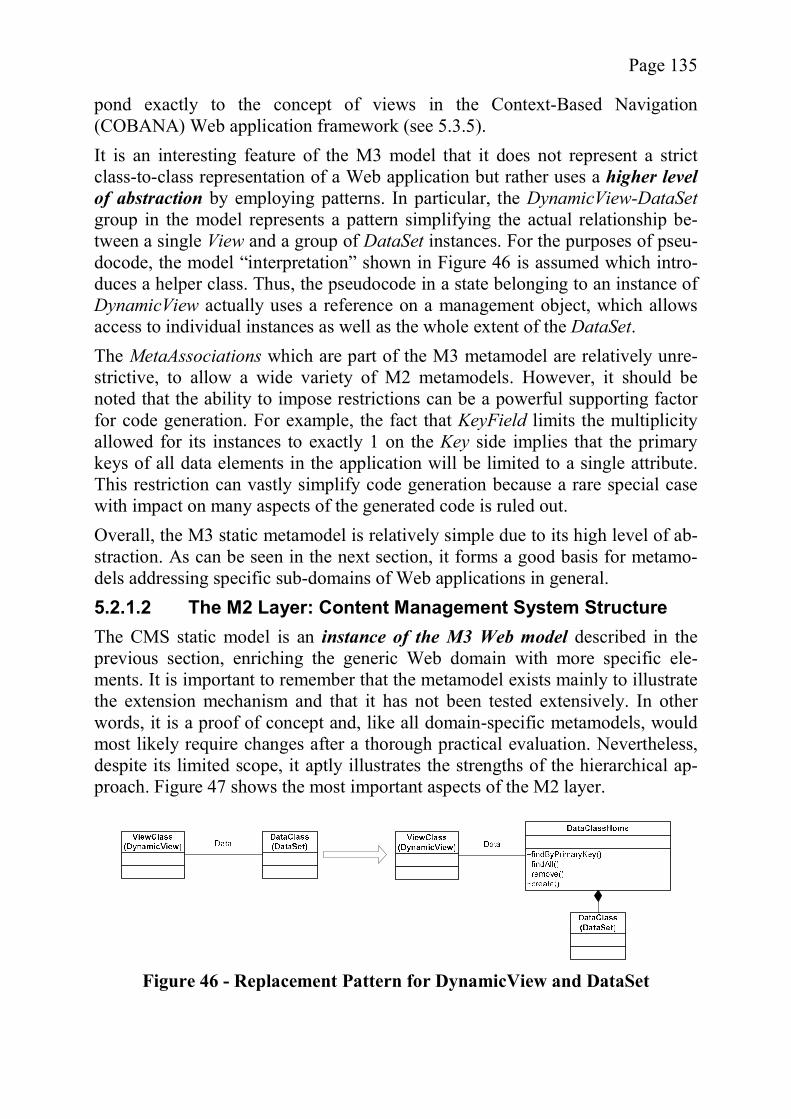
Page 135
pond exactly to the concept of views in the Context-Based Navigation (COBANA) Web application framework (see 5.3.5). It is an interesting feature of the M3 model that it does not represent a strict class-to-class representation of a Web application but rather uses a higher level of abstraction by employing patterns. In particular, the DynamicView-DataSetgroup in the model represents a pattern simplifying the actual relationship be-tween a single View and a group of DataSet instances. For the purposes of pseu-docode, the model “interpretation” shown in Figure 46 is assumed which intro-duces a helper class. Thus, the pseudocode in a state belonging to an instance of DynamicView actually uses a reference on a management object, which allows access to individual instances as well as the whole extent of the DataSet. The MetaAssociations which are part of the M3 metamodel are relatively unre-strictive, to allow a wide variety of M2 metamodels. However, it should be noted that the ability to impose restrictions can be a powerful supporting factor for code generation. For example, the fact that KeyField limits the multiplicity allowed for its instances to exactly 1 on the Key side implies that the primary keys of all data elements in the application will be limited to a single attribute. This restriction can vastly simplify code generation because a rare special case with impact on many aspects of the generated code is ruled out. Overall, the M3 static metamodel is relatively simple due to its high level of ab-straction. As can be seen in the next section, it forms a good basis for metamo-dels addressing specific sub-domains of Web applications in general. 5.2.1.2 The M2 Layer: Content Management System Structure The CMS static model is an instance of the M3 Web model described in the previous section, enriching the generic Web domain with more specific ele-ments. It is important to remember that the metamodel exists mainly to illustrate the extension mechanism and that it has not been tested extensively. In other words, it is a proof of concept and, like all domain-specific metamodels, would most likely require changes after a thorough practical evaluation. Nevertheless, despite its limited scope, it aptly illustrates the strengths of the hierarchical ap-proach. Figure 47 shows the most important aspects of the M2 layer.
Figure 46 - Replacement Pattern for DynamicView and DataSet
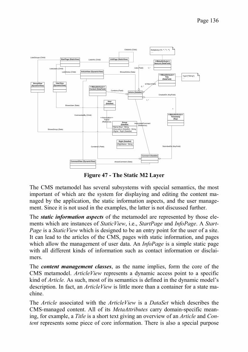
Page 136
The CMS metamodel has several subsystems with special semantics, the most important of which are the system for displaying and editing the content ma-naged by the application, the static information aspects, and the user manage-ment. Since it is not used in the examples, the latter is not discussed further. The static information aspects of the metamodel are represented by those ele-ments which are instances of StaticView, i.e., StartPage and InfoPage. A Start-Page is a StaticView which is designed to be an entry point for the user of a site. It can lead to the articles of the CMS, pages with static information, and pages which allow the management of user data. An InfoPage is a simple static page with all different kinds of information such as contact information or disclai-mers. The content management classes, as the name implies, form the core of the CMS metamodel. ArticleView represents a dynamic access point to a specific kind of Article. As such, most of its semantics is defined in the dynamic model’s description. In fact, an ArticleView is little more than a container for a state ma-chine. The Article associated with the ArticleView is a DataSet which describes the CMS-managed content. All of its MetaAttributes carry domain-specific mean-ing, for example, a Title is a short text giving an overview of an Article and Con-tent represents some piece of core information. There is also a special purpose
StartPage (StaticView) InfoPage (StaticView)
ArticleView (DynamicView)
CommentView (DynamicView)
Article (DataSet)
Comment (DataSet)
<<MetaAttribute>>Timestamp
(Key)
<<MetaAttribute>>Content (DataField)
<<MetaAttribute>>Title
(DataField)
<<MetaAttribute>>ItemList (DataField)
1..*
1
CreatedOn (KeyField)
SubmitedOn (KeyField)
0..*
1..*Lists (Field)
IsTitled (Field)
Contains (Field)
Contains2 (Field)
showsComment (Data)
ShowsArticle (Data)
CommentedBy (Child)
ListArticles (Child)
ListsInfo (Child)
GroupView(DynamicView)
+Name (Key) : String+Description (DataSet) : String+Rights : Right (DataSet)
Group(DataSet)
ShowsGroup (Data)
ListsGroups (Child)
AssociatedComment(Reference)
Type={"String"}....
Multiplicity={"0..*", "1..*"}.....
ChildInfo (Child)
User(DataSet)
UserView(DynamicView)
<<Association>>PartOf
(Reference)
ShowsUser (Data)
+RightName : StringRight (DataSet)
ListsUsers (Child)
Figure 47 - The Static M2 Layer

Page 137
MetaAttribute called ItemList used for the creation of lists of items, e.g., steps in a user manual, ingredients of a recipe, or bibliographical references. The CMS metamodel is a good example how a generic metamodel, in this case the M3 Web application metamodel, can be enriched using instantiation. Due to the fact that the elements of the CMS metamodel have more specific semantics, they are more suitable for any kind of automated task which requires a program to make assumptions about its data such as code generation or providing seman-tic data about a Web application. The support of semantic Web applications is a direction which can only be skirted here because it is beyond the scope of this work. Briefly, a model of a Web application based on a metamodel as specific as the CMS metamodel, can serve as a good basis for the creation of RDF documents to support semantic Web browsers. Even the simple distinction between a StartPage, an ArticleView, and an InfoPage can allow intelligent browsers to assemble a site summary. More sophisticated versions of the M2 metamodel might distinguish between page fragments displaying legal information, advertisements, and other catego-ries of static information. The benefit for code generation on the other hand is a major focus of the discus-sion later in this chapter. Looking at the example of the Article class, it is possi-ble to point out several beneficial aspects of the added semantics, in particular due to the concept of MetaAttributes unique to OMEGA. The existence of M2 MetaAttributes implies that each attribute found in the persistent objects of a de-signed application will have an interpretation the code generator can use to au-tomatically produce business logic. For example, an Article might be represented by its Title in a list. Also, the primary key of an object can be gener-ated automatically since it is a Timestamp. Input fields for Content attributes will be given larger text areas than other String-based attributes such as Title. There are even more benefits for the dynamic metamodels that will be discussed in section 5.2.2.2.
5.2.2 The Dynamic Metamodels The dynamic metamodel hierarchy defines the behavior associated with the ele-ments of the static models described in the previous two sections. The ontologi-cal metamodels are all instances of the linguistic OMEGA/Dynamic metamodel. The M3 layer metamodel is described first, followed by the Content Manage-ment elements of M2. 5.2.2.1 The M3 Layer: Web Application Behavior There is only one MetaClass at the M3 layer with an inherent dynamic behavior and therefore only a single MetaStateChart has to be defined. Figure 48 shows the metamodel for DynamicViewBehavior which serves as a metaelement for the StateCharts used by instances of DynamicView.

Page 138
For the Web context, special semantics is associated with the linguistic meta-model elements provided by OMEGA/Dynamic. The generic parameters and return types of OMEGA/Dynamic are replaced by tables with key-value pairs. Since not all States need the same parameters, the exact nature of both the para-meters and return types have to be described for all implicit MetaStates. Only States whose expected input and provided output match can succeed each other meaningfully. While the implicit MetaStates provided by the M3 metamodel generally fulfill this criterion where needed, care has to be taken by a modeler when creating instances which define their own pseudocode. The return value of these explicit MetaStates is created automatically based on the ActionFragmentscalled and must provide all values required by the successor. The semantics of Signals is divided into two special cases, user input and in-ternal signals. View and its instances are the only elements that directly receive signals from the user. The code generator is responsible for providing links, sending the proper signal to allow all the defined transitions. The rest of the Sig-nals are considered internal, a case which does not occur in the examples and is therefore not explained in detail. The DynamicViewBehavior MetaStateChart provides many ActionFragments to facilitate the writing of pseudocode, for example allowing the creation of Web page form elements. For example, the createTextInput ActionFragment creates a text field on the output Web page of the State, passing the text field’s content to the next State in the key-value table parameter. However, there is no Action-
Figure 48 - The Dynamic M3 Layer
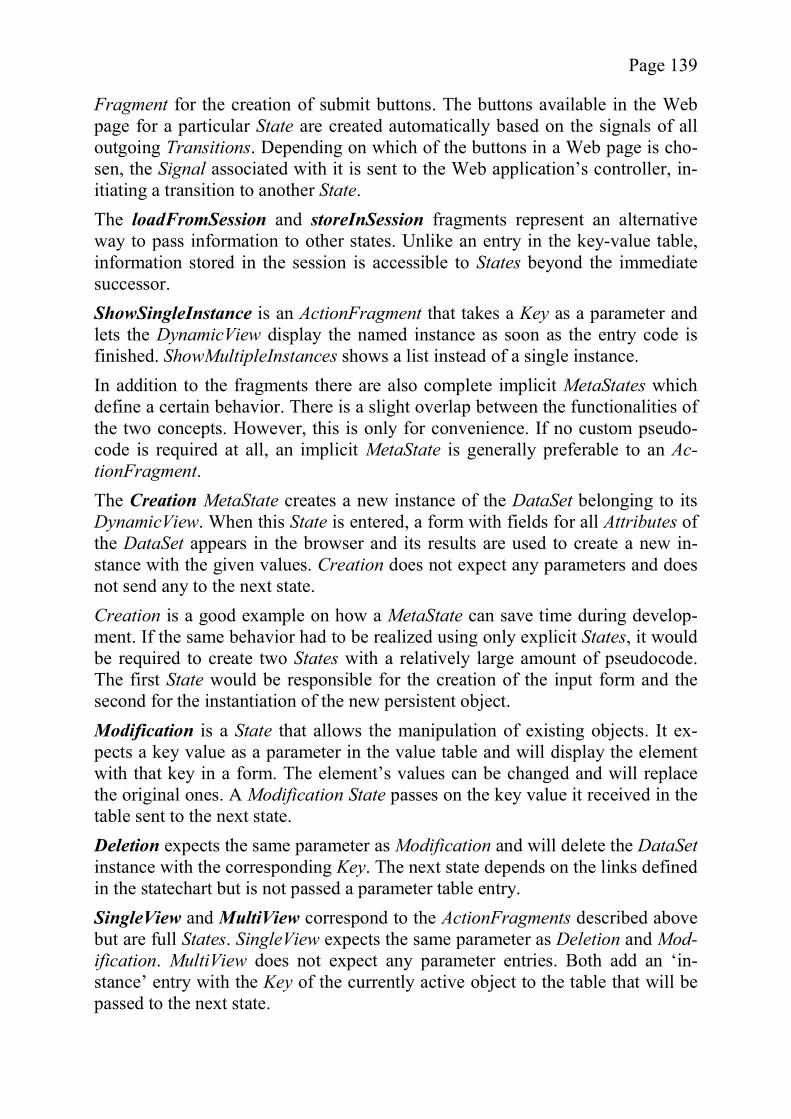
Page 139
Fragment for the creation of submit buttons. The buttons available in the Web page for a particular State are created automatically based on the signals of all outgoing Transitions. Depending on which of the buttons in a Web page is cho-sen, the Signal associated with it is sent to the Web application’s controller, in-itiating a transition to another State. The loadFromSession and storeInSession fragments represent an alternative way to pass information to other states. Unlike an entry in the key-value table, information stored in the session is accessible to States beyond the immediate successor. ShowSingleInstance is an ActionFragment that takes a Key as a parameter and lets the DynamicView display the named instance as soon as the entry code is finished. ShowMultipleInstances shows a list instead of a single instance. In addition to the fragments there are also complete implicit MetaStates which define a certain behavior. There is a slight overlap between the functionalities of the two concepts. However, this is only for convenience. If no custom pseudo-code is required at all, an implicit MetaState is generally preferable to an Ac-tionFragment. The Creation MetaState creates a new instance of the DataSet belonging to its DynamicView. When this State is entered, a form with fields for all Attributes of the DataSet appears in the browser and its results are used to create a new in-stance with the given values. Creation does not expect any parameters and does not send any to the next state. Creation is a good example on how a MetaState can save time during develop-ment. If the same behavior had to be realized using only explicit States, it would be required to create two States with a relatively large amount of pseudocode. The first State would be responsible for the creation of the input form and the second for the instantiation of the new persistent object. Modification is a State that allows the manipulation of existing objects. It ex-pects a key value as a parameter in the value table and will display the element with that key in a form. The element’s values can be changed and will replace the original ones. A Modification State passes on the key value it received in the table sent to the next state. Deletion expects the same parameter as Modification and will delete the DataSetinstance with the corresponding Key. The next state depends on the links defined in the statechart but is not passed a parameter table entry. SingleView and MultiView correspond to the ActionFragments described above but are full States. SingleView expects the same parameter as Deletion and Mod-ification. MultiView does not expect any parameter entries. Both add an ‘in-stance’ entry with the Key of the currently active object to the table that will be passed to the next state.
Page 140
5.2.2.2 The M2 Layer: Content Management System Behavior The CMS layer adds some additional functionality to the basic Web behavior defined in the M3 layer. Figure 49 shows the three MetaStateCharts introduced by the M2 layer. Of particular interest, as a proof-of-concept, is the ArticleBeha-vior, the first non-Web element to display dynamic behavior. The elements of the metamodel necessary for the further discussion are explained below. Several ActionFragments are defined for the M2 layer. The ActionFragmentsgetApproved and setApproved can be used to set and read the implicit Booleanvariable Approved, which is automatically added to all Articles. Both fragments are intended to be called by other classes to allow distinguishing between these two different ‘modes’ of Article. Of course, the approval mechanism can also be modeled using states, setting the Approved value internally, if more complex review processes have to be modeled. The approval flag is used by some of the MetaStates defined for M2. In addition to the ActionFragments, there are also several MetaStates. ShowAp-provedArticles is a MetaState which only shows those Articles where Approvedis true, otherwise it behaves like an M3 MultiView. ShowUnapprovedArticles is
Figure 49 - The Dynamic M2 Layer
Page 141
another MetaState that only shows those Articles which are not approved. Both MetaStates do not expect any parameters but upon exit will pass a string consist-ing of the Timestamp and the Title of the selected Article to their follow-up Statein the key-value table. ReviewArticle is a State that represents a Web page very similar to that used by Modification but offers two exits, one for approval and one for rejection. There are two different requiredSubstates, one that will be reached when the Article is approved and one that is reached when it is not. The Timestamp of the Article is passed as a parameter to the next State. ReviewArticle can be interpreted as a pattern flexibly applicable to many similar situations as can be seen in the ex-amples shown in section 5.4.
5.3 Prototypical Implementations While the example in the previous section shows that the extension mechanism described in this chapter can be used to model domain-specific hierarchies, the question is whether these hierarchies can be used to facilitate the generation of application code. In order to be able to evaluate to what extent the intended im-provements of the OMEGA extension mechanism are realized, it is necessary to provide a prototypical tool implementation. The prototype, which will be described in this section, consists of three plugins for the Eclipse tool integration platform [62], some stand-alone support tools, code generation templates, and a Web application framework. However, due to the purpose of the prototype as a test bed for the evaluation in section 6.1, not all of these elements are given the same amount of attention. Instead the following approach is taken. First, the general plugin architecture is briefly described to explain the overall structure of the prototype. For this purpose the defined plugin interfaces are ex-plained and it is described which plugins implement which interfaces. The first plugin to be discussed is a generic modeling tool. Not being tied to the OMEGA metamodels in particular, it provides an interface which allows the registration of generic metamodels. Described next, is a metamodel data structure implementing this interface. The plugin can load models which use an ontological metamodel based on the OMEGA and OMEGA/Dynamic linguistic metamodels. Extending both the modeling tool and the data structure plugin is a code genera-tion module. Since the goal of this dissertation is to improve the input provided to code generators and not the code generators themselves, the module is of a purely proof-of-concept nature and should not be considered complete or stable beyond the test cases. Nevertheless, it is described in some detail to be able to evaluate the ability of the extension mechanism to support code generation.

Page 142
Finally, to show the advantages of a close relationship between models and cod-ing infrastructure, a Web application framework had to be implemented. The COBANA framework has been tested and extended in the context of several non-model-driven student projects. Since COBANA is merely used as an exam-ple framework, it is only examined in so far as is relevant for the evaluation of the prototype.
5.3.1 General Plugin Architecture Figure 50 shows the conceptual structure of the plugins developed for the proto-type. OMEGAPlugin is the main plugin which provides three extension points that allow other plugins to use its infrastructure. As shown in the Figure, it is also possible that a single plugin implements more than one point. Not shown is the fact, that an extension point can be implemented multiple times. The Defaul-tExtension implements both IMetaModel and IOMEGAEditPartFactory twice, once for OMEGA and once for OMEGA/Dynamic. OMEGAPlugin is a generic editor for drawing models. The concrete syntax or look of these models is variable and depends on an external object factory which implements the IOMEGAEditPartFactory interface. By providing a different factory, the look of the graphical elements can be changed. In the prototype, the IOMEGAEditPartFactory interface is implemented twice, providing graphical elements for both the static and the dynamic models. The abstract syntax of the model is determined by the plugins implementing the IMetaModel which define the types of nodes and edges allowed in the model. This interface is also implemented twice, once for each model type.
DefaultModelGenerator
ICodeGenerator
DefaultExtension
IMetaModel
OMEGAPlugin IOMEGAEditPartFactory
Figure 50 - Prototype Plugin Structure
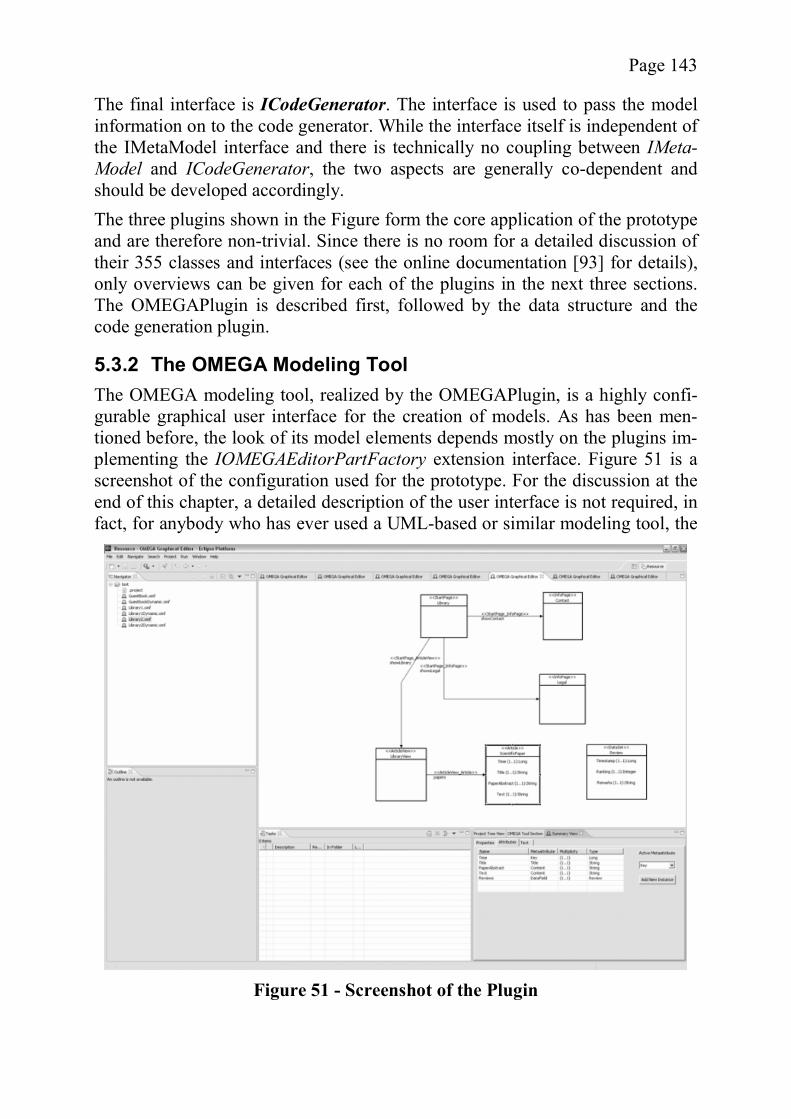
Page 143
The final interface is ICodeGenerator. The interface is used to pass the model information on to the code generator. While the interface itself is independent of the IMetaModel interface and there is technically no coupling between IMeta-Model and ICodeGenerator, the two aspects are generally co-dependent and should be developed accordingly. The three plugins shown in the Figure form the core application of the prototype and are therefore non-trivial. Since there is no room for a detailed discussion of their 355 classes and interfaces (see the online documentation [93] for details), only overviews can be given for each of the plugins in the next three sections. The OMEGAPlugin is described first, followed by the data structure and the code generation plugin.
5.3.2 The OMEGA Modeling Tool The OMEGA modeling tool, realized by the OMEGAPlugin, is a highly confi-gurable graphical user interface for the creation of models. As has been men-tioned before, the look of its model elements depends mostly on the plugins im-plementing the IOMEGAEditorPartFactory extension interface. Figure 51 is a screenshot of the configuration used for the prototype. For the discussion at the end of this chapter, a detailed description of the user interface is not required, in fact, for anybody who has ever used a UML-based or similar modeling tool, the
Figure 51 - Screenshot of the Plugin

Page 144
use of the plugin should be intuitive. Since the plugin is intended for an end user of a metamodel hierarchy, it does not support a graphical editing of the metamo-dels. The creation, saving, and loading of custom metamodels is realized through rudimentary helper tools, existing outside of the plugin. As discussed in the previous section, the OMEGAPlugin provides three exten-sion points which require the implementation of specific interfaces. Since the interfaces and their actual implementations are best explained together, they are not discussed in the context of the main plugin and are instead delegated to the sections presenting their corresponding implementations.
5.3.3 The OMEGA Data Structure Plugin The plugin containing the data structure needed for OMEGA is called Defaul-tExtension. It implements both the IOMEGAEditPartFactory and the IMetaMo-del interface twice, providing the concrete and abstract syntax for both the static and the dynamic metamodel. Since its functionality comprises two aspects, both are discussed separately. The concrete syntax of the metamodel depends on so-called EditParts, a con-cept defined for the Draw2D Eclipse plugin. An EditPart contains the rules for creating a graphical representation of a model element. The principle of these wrappers is simple. Every time the editor is asked to display a model element, a lookup is performed to determine what kind of graphical element (and therefore EditPart) corresponds to the model element. The new EditPart wraps the object representing the model element and, based on the model element data, creates a graphical representation. The first extension of IOMEGAEditPartFactory, realized by the StaticDataclass, provides graphical elements which look almost like UML classes and as-sociations. While there are slight deviations, these are purely cosmetic and due to the prototypical nature of the plugin. These do not in any way compromise the intended compatibility with UML. Similarly, the extension DynamicDatarepresents a simplified UML statechart diagram. Of greater interest for the discussion of the extension mechanism is the abstract syntax of the model. The linguistic vs. ontological dualism found in the OMEGA models is also reflected in the data structures of the plugin. For each kind of metamodel, a data structure exists, and the individual ontological in-stances are represented through object states. Since the scope of the editor is limited to the manipulations made by the end-user, its model does not support a full metamodel hierarchy, focusing instead on the lowest layer. Only the relevant information from the higher layers is added as metainformation, similar to UML tags. Such a simplification is only possible because the metalevels are “read-only” at the end user level. Thus, most of the information described in the metamodel hierarchy can be ignored in this special
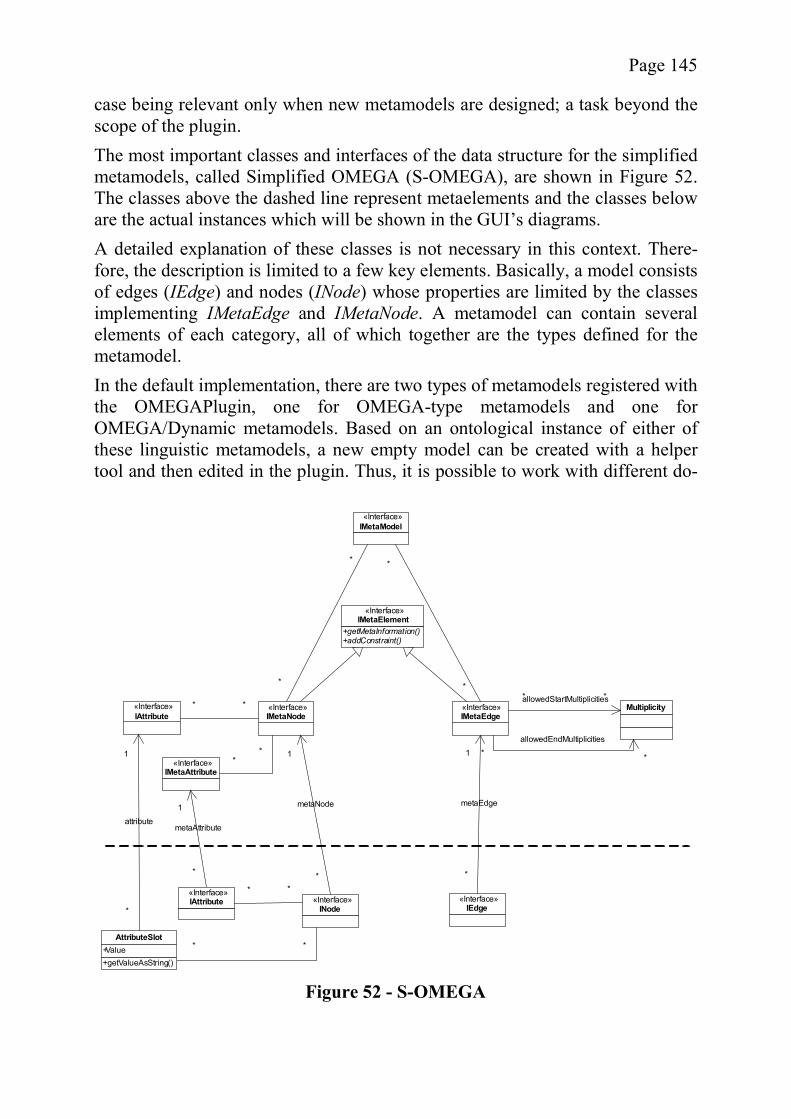
Page 145
case being relevant only when new metamodels are designed; a task beyond the scope of the plugin. The most important classes and interfaces of the data structure for the simplified metamodels, called Simplified OMEGA (S-OMEGA), are shown in Figure 52. The classes above the dashed line represent metaelements and the classes below are the actual instances which will be shown in the GUI’s diagrams. A detailed explanation of these classes is not necessary in this context. There-fore, the description is limited to a few key elements. Basically, a model consists of edges (IEdge) and nodes (INode) whose properties are limited by the classes implementing IMetaEdge and IMetaNode. A metamodel can contain several elements of each category, all of which together are the types defined for the metamodel. In the default implementation, there are two types of metamodels registered with the OMEGAPlugin, one for OMEGA-type metamodels and one for OMEGA/Dynamic metamodels. Based on an ontological instance of either of these linguistic metamodels, a new empty model can be created with a helper tool and then edited in the plugin. Thus, it is possible to work with different do-
«Interface»IMetaNode
«Interface»IMetaEdge
+getMetaInformation()+addConstraint()
«Interface»IMetaElement
«Interface»IMetaModel
*
*
*
*
«Interface»IMetaAttribute
**
«Interface»IAttribute
** Multiplicity
* *
allowedEndMultiplicities
**allowedStartMultiplicities
«Interface»INode
**
+getValueAsString()
AttributeSlot+Value
1
*
metaNode1
*
metaAttribute
«Interface»IAttribute
**
1
*
attribute
«Interface»IEdge
1
*
metaEdge
Figure 52 - S-OMEGA
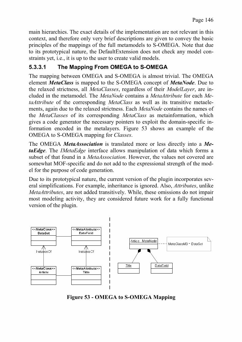
Page 146
main hierarchies. The exact details of the implementation are not relevant in this context, and therefore only very brief descriptions are given to convey the basic principles of the mappings of the full metamodels to S-OMEGA. Note that due to its prototypical nature, the DefaultExtension does not check any model con-straints yet, i.e., it is up to the user to create valid models. 5.3.3.1 The Mapping From OMEGA to S-OMEGA The mapping between OMEGA and S-OMEGA is almost trivial. The OMEGA element MetaClass is mapped to the S-OMEGA concept of MetaNode. Due to the relaxed strictness, all MetaClasses, regardless of their ModelLayer, are in-cluded in the metamodel. The MetaNode contains a MetaAttribute for each Me-taAttribute of the corresponding MetaClass as well as its transitive metaele-ments, again due to the relaxed strictness. Each MetaNode contains the names of the MetaClasses of its corresponding MetaClass as metainformation, which gives a code generator the necessary pointers to exploit the domain-specific in-formation encoded in the metalayers. Figure 53 shows an example of the OMEGA to S-OMEGA mapping for Classes. The OMEGA MetaAssociation is translated more or less directly into a Me-taEdge. The IMetaEdge interface allows manipulation of data which forms a subset of that found in a MetaAssociation. However, the values not covered are somewhat MOF-specific and do not add to the expressional strength of the mod-el for the purpose of code generation. Due to its prototypical nature, the current version of the plugin incorporates sev-eral simplifications. For example, inheritance is ignored. Also, Attributes, unlike MetaAttributes, are not added transitively. While, these omissions do not impair most modeling activity, they are considered future work for a fully functional version of the plugin.
Figure 53 - OMEGA to S-OMEGA Mapping
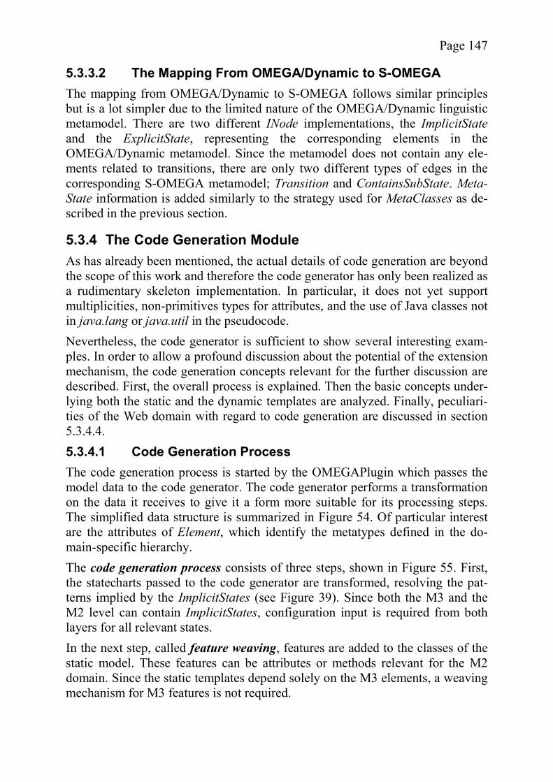
Page 147
5.3.3.2 The Mapping From OMEGA/Dynamic to S-OMEGA The mapping from OMEGA/Dynamic to S-OMEGA follows similar principles but is a lot simpler due to the limited nature of the OMEGA/Dynamic linguistic metamodel. There are two different INode implementations, the ImplicitStateand the ExplicitState, representing the corresponding elements in the OMEGA/Dynamic metamodel. Since the metamodel does not contain any ele-ments related to transitions, there are only two different types of edges in the corresponding S-OMEGA metamodel; Transition and ContainsSubState. Meta-State information is added similarly to the strategy used for MetaClasses as de-scribed in the previous section.
5.3.4 The Code Generation Module As has already been mentioned, the actual details of code generation are beyond the scope of this work and therefore the code generator has only been realized as a rudimentary skeleton implementation. In particular, it does not yet support multiplicities, non-primitives types for attributes, and the use of Java classes not in java.lang or java.util in the pseudocode. Nevertheless, the code generator is sufficient to show several interesting exam-ples. In order to allow a profound discussion about the potential of the extension mechanism, the code generation concepts relevant for the further discussion are described. First, the overall process is explained. Then the basic concepts under-lying both the static and the dynamic templates are analyzed. Finally, peculiari-ties of the Web domain with regard to code generation are discussed in section 5.3.4.4. 5.3.4.1 Code Generation Process The code generation process is started by the OMEGAPlugin which passes the model data to the code generator. The code generator performs a transformation on the data it receives to give it a form more suitable for its processing steps. The simplified data structure is summarized in Figure 54. Of particular interest are the attributes of Element, which identify the metatypes defined in the do-main-specific hierarchy. The code generation process consists of three steps, shown in Figure 55. First, the statecharts passed to the code generator are transformed, resolving the pat-terns implied by the ImplicitStates (see Figure 39). Since both the M3 and the M2 level can contain ImplicitStates, configuration input is required from both layers for all relevant states. In the next step, called feature weaving, features are added to the classes of the static model. These features can be attributes or methods relevant for the M2 domain. Since the static templates depend solely on the M3 elements, a weaving mechanism for M3 features is not required.
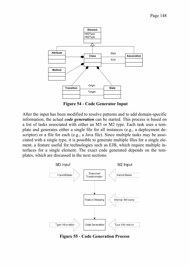
Page 148
After the input has been modified to resolve patterns and to add domain-specific information, the actual code generation can be started. This process is based on a list of tasks associated with either an M3 or M2 type. Each task uses a tem-plate and generates either a single file for all instances (e.g., a deployment de-scriptor) or a file for each (e.g., a Java file). Since multiple tasks may be asso-ciated with a single type, it is possible to generate multiple files for a single ele-ment, a feature useful for technologies such as EJB, which require multiple in-terfaces for a single element. The exact code generated depends on the tem-plates, which are discussed in the next sections.
Class AssociationStart
End
+M3Type+M2Type
Element
Transition StateOrigin
Target
Attribute
Method
Figure 54 - Code Generator Input
Figure 55 - Code Generation Process
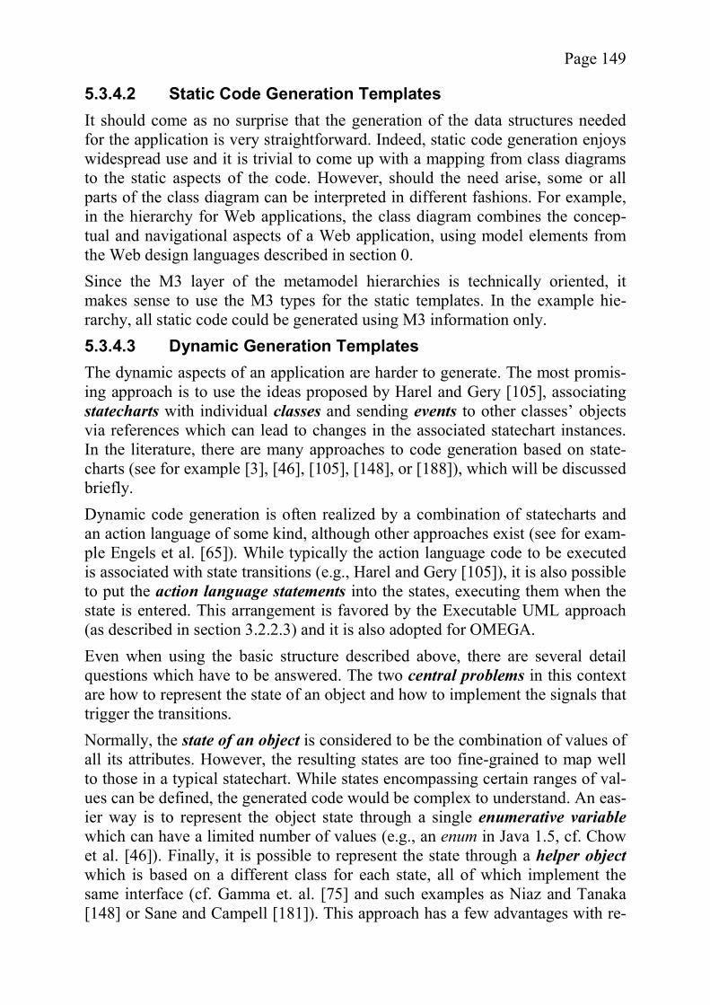
Page 149
5.3.4.2 Static Code Generation Templates It should come as no surprise that the generation of the data structures needed for the application is very straightforward. Indeed, static code generation enjoys widespread use and it is trivial to come up with a mapping from class diagrams to the static aspects of the code. However, should the need arise, some or all parts of the class diagram can be interpreted in different fashions. For example, in the hierarchy for Web applications, the class diagram combines the concep-tual and navigational aspects of a Web application, using model elements from the Web design languages described in section 0. Since the M3 layer of the metamodel hierarchies is technically oriented, it makes sense to use the M3 types for the static templates. In the example hie-rarchy, all static code could be generated using M3 information only. 5.3.4.3 Dynamic Generation Templates The dynamic aspects of an application are harder to generate. The most promis-ing approach is to use the ideas proposed by Harel and Gery [105], associating statecharts with individual classes and sending events to other classes’ objects via references which can lead to changes in the associated statechart instances. In the literature, there are many approaches to code generation based on state-charts (see for example [3], [46], [105], [148], or [188]), which will be discussed briefly. Dynamic code generation is often realized by a combination of statecharts and an action language of some kind, although other approaches exist (see for exam-ple Engels et al. [65]). While typically the action language code to be executed is associated with state transitions (e.g., Harel and Gery [105]), it is also possible to put the action language statements into the states, executing them when the state is entered. This arrangement is favored by the Executable UML approach (as described in section 3.2.2.3) and it is also adopted for OMEGA. Even when using the basic structure described above, there are several detail questions which have to be answered. The two central problems in this context are how to represent the state of an object and how to implement the signals that trigger the transitions. Normally, the state of an object is considered to be the combination of values of all its attributes. However, the resulting states are too fine-grained to map well to those in a typical statechart. While states encompassing certain ranges of val-ues can be defined, the generated code would be complex to understand. An eas-ier way is to represent the object state through a single enumerative variablewhich can have a limited number of values (e.g., an enum in Java 1.5, cf. Chow et al. [46]). Finally, it is possible to represent the state through a helper objectwhich is based on a different class for each state, all of which implement the same interface (cf. Gamma et. al. [75] and such examples as Niaz and Tanaka [148] or Sane and Campell [181]). This approach has a few advantages with re-

Page 150
gard to the handling of signals and is therefore used for the DefaultCodeGenera-tor. It is generally agreed upon that there are two basic ways to realize signals in an environment which is mainly single-threaded or makes thread-related questions transparent to the developer. The first is to use an event-based approach, and the second is to use method calls (e.g., Harel and Gery [105] or Ali and Tanaka [3]). In the case of method calls, sending a signal means calling a method of that name in the target object. Events on the other hand rely on a central dispatcher which is fed new events and distributes them to their target objects. The main difference between the two concepts is that in one case the execution of the ob-ject’s action statements is frozen until the method call is finished, while an event will only pass control to the target as soon as its own statechart is stable, i.e., not executing any statements. Using a helper object for the representation of states also facilitates signal han-dling. The reason is that each helper class can implement the methods or event listeners required for the state it represents and implement the behavior required in that particular state. Thereby, a clean separation of state code is achieved in the implementation. In the code generator plugin, both types of signals are used, depending on their role in the model. Figure 56 shows the code generation approach chosen for OMEGA. The pseu-do-UML model on the right shows a static class from the OMEGA model and its associated statechart, represented by a package. On the right, a simplified repre-sentation of the generated code is shown. As mentioned above, each state is rea-lized by a helper class. In the example, signals are passed as events to the chan-geState() method, a realization of signals as method calls would include a me-thod mySignal() in the generated class called MyClass. An interesting aspect of the generated code is the MyStateBaseClass. A common baseclass for all states is useful, because it is the ideal location for all kinds of
Figure 56 - Code Generation Concept

Page 151
helper methods. In particular, ActionFragments are realized as method calls in the baseclass. The code generated for a State depends on both of its MetaStates. Should a Statehave both an M2 and M3 type, the M2 type is used, but in most cases there is only one type. Typically a different template is provided for each MetaState. If the state is based on a non-implicit MetaState, the pseudocode associated with the state is added. Otherwise the behavior is determined by the template. The action language used for the pseudocode sections in the plugin is a subset of Java since it makes little sense to define a new language for the purposes of a prototype. Similar arguments are brought forth by Harel and Gery who use C++ in their O-MATE tool [105]. It should be obvious that there are some limitations to the chosen approach. In particular, the statecharts used as input for the code generator are somewhat simplistic. However, it can be argued that the concepts tested here will be usable with more complex statecharts as well. In particular, by using helper objects to represent the states, the code generation techniques devised by Ali and Tanaka can easily be added. Thus it becomes possible to cover more advanced features such as concurrency or substates (cf. [3]). 5.3.4.4 Code Generation for the Web Domain While the code templates designed for the Web domain use the same basic prin-ciples as the general case described above, a few slight alterations are needed to accommodate some particularities. The Web M3 model used in the examples implies the following assumptions. Any (transitive) instance of View is considered to be part of the navigational model of the application. The concepts of “childviews” and “subviews” corres-pond to the equivalent constructs already explained in the context of Web design languages. Thus, the whole static navigation is encoded in the static diagram. The various ActionFragments of the DynamicViewBehavior are used to assem-ble a page consisting of text information, links, and edit fields. After a code block has been finished, the page is assumed to be visible to the user who can use the various links provided. Each of the links represents a single possible sig-nal to change the State of the currently active DynamicView. All “static” naviga-tion is defined in the static diagram. A DynamicView starts in the State which is identified as the initial state due to its name whenever the user navigates to this DynamicView. This implies that leaving the DynamicView via static navigation will reset the state.
5.3.5 A Brief Introduction to the COBANA Framework One of the core ideas of the code generation strategy used in this context is the use of a suitable framework, which allows fast and easy template implementa-tion, to avoid the problems encountered by past approaches (see section 3.2.1).
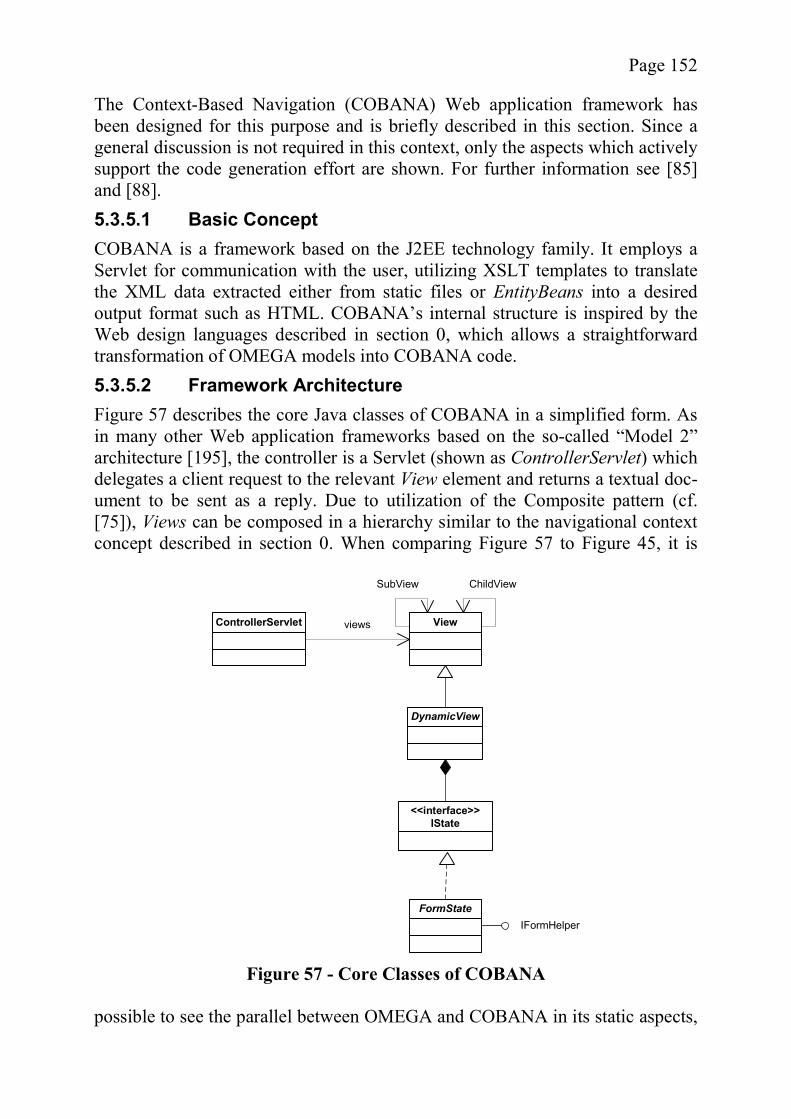
Page 152
The Context-Based Navigation (COBANA) Web application framework has been designed for this purpose and is briefly described in this section. Since a general discussion is not required in this context, only the aspects which actively support the code generation effort are shown. For further information see [85] and [88]. 5.3.5.1 Basic Concept COBANA is a framework based on the J2EE technology family. It employs a Servlet for communication with the user, utilizing XSLT templates to translate the XML data extracted either from static files or EntityBeans into a desired output format such as HTML. COBANA’s internal structure is inspired by the Web design languages described in section 0, which allows a straightforward transformation of OMEGA models into COBANA code. 5.3.5.2 Framework Architecture Figure 57 describes the core Java classes of COBANA in a simplified form. As in many other Web application frameworks based on the so-called “Model 2” architecture [195], the controller is a Servlet (shown as ControllerServlet) which delegates a client request to the relevant View element and returns a textual doc-ument to be sent as a reply. Due to utilization of the Composite pattern (cf. [75]), Views can be composed in a hierarchy similar to the navigational context concept described in section 0. When comparing Figure 57 to Figure 45, it is
possible to see the parallel between OMEGA and COBANA in its static aspects,
ControllerServlet View
DynamicView
views
ChildViewSubView
FormStateIFormHelper
<<interface>>IState
Figure 57 - Core Classes of COBANA
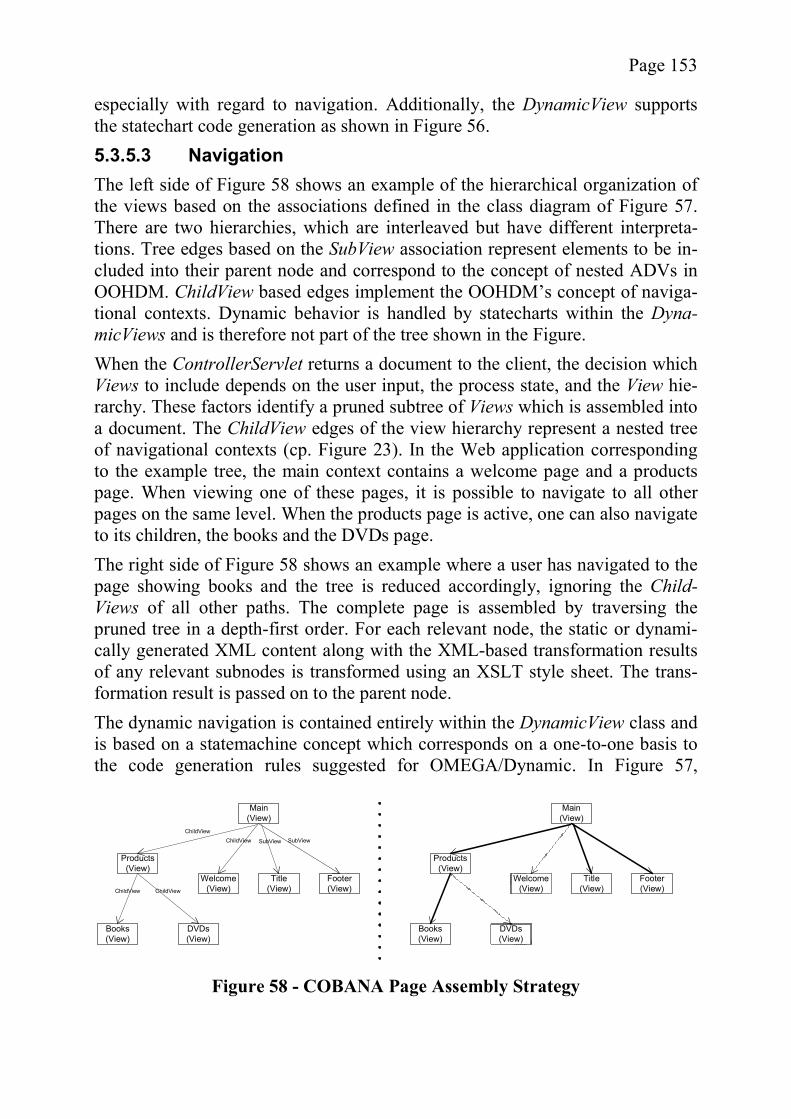
Page 153
especially with regard to navigation. Additionally, the DynamicView supports the statechart code generation as shown in Figure 56. 5.3.5.3 Navigation The left side of Figure 58 shows an example of the hierarchical organization of the views based on the associations defined in the class diagram of Figure 57. There are two hierarchies, which are interleaved but have different interpreta-tions. Tree edges based on the SubView association represent elements to be in-cluded into their parent node and correspond to the concept of nested ADVs in OOHDM. ChildView based edges implement the OOHDM’s concept of naviga-tional contexts. Dynamic behavior is handled by statecharts within the Dyna-micViews and is therefore not part of the tree shown in the Figure. When the ControllerServlet returns a document to the client, the decision which Views to include depends on the user input, the process state, and the View hie-rarchy. These factors identify a pruned subtree of Views which is assembled into a document. The ChildView edges of the view hierarchy represent a nested tree of navigational contexts (cp. Figure 23). In the Web application corresponding to the example tree, the main context contains a welcome page and a products page. When viewing one of these pages, it is possible to navigate to all other pages on the same level. When the products page is active, one can also navigate to its children, the books and the DVDs page. The right side of Figure 58 shows an example where a user has navigated to the page showing books and the tree is reduced accordingly, ignoring the Child-Views of all other paths. The complete page is assembled by traversing the pruned tree in a depth-first order. For each relevant node, the static or dynami-cally generated XML content along with the XML-based transformation results of any relevant subnodes is transformed using an XSLT style sheet. The trans-formation result is passed on to the parent node. The dynamic navigation is contained entirely within the DynamicView class and is based on a statemachine concept which corresponds on a one-to-one basis to the code generation rules suggested for OMEGA/Dynamic. In Figure 57,
Main (View)
Title (View)
Footer (View)
SubView SubView
Welcome (View)
Products (View)
Books (View)
DVDs (View)
ChildViewChildView
ChildView ChildView
Main (View)
Title (View)
Footer (View)
Welcome (View)
Products (View)
Books (View)
DVDs (View)
Figure 58 - COBANA Page Assembly Strategy
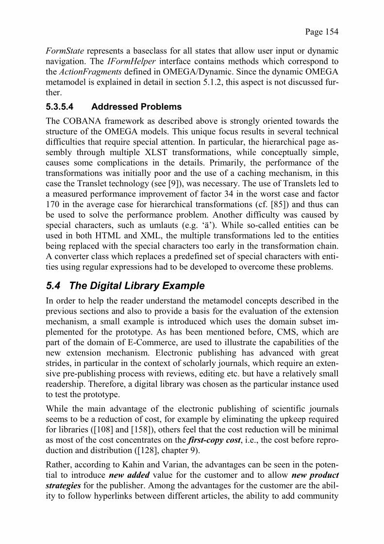
Page 154
FormState represents a baseclass for all states that allow user input or dynamic navigation. The IFormHelper interface contains methods which correspond to the ActionFragments defined in OMEGA/Dynamic. Since the dynamic OMEGA metamodel is explained in detail in section 5.1.2, this aspect is not discussed fur-ther. 5.3.5.4 Addressed Problems The COBANA framework as described above is strongly oriented towards the structure of the OMEGA models. This unique focus results in several technical difficulties that require special attention. In particular, the hierarchical page as-sembly through multiple XLST transformations, while conceptually simple, causes some complications in the details. Primarily, the performance of the transformations was initially poor and the use of a caching mechanism, in this case the Translet technology (see [9]), was necessary. The use of Translets led to a measured performance improvement of factor 34 in the worst case and factor 170 in the average case for hierarchical transformations (cf. [85]) and thus can be used to solve the performance problem. Another difficulty was caused by special characters, such as umlauts (e.g. ‘ä’). While so-called entities can be used in both HTML and XML, the multiple transformations led to the entities being replaced with the special characters too early in the transformation chain. A converter class which replaces a predefined set of special characters with enti-ties using regular expressions had to be developed to overcome these problems.
5.4 The Digital Library Example In order to help the reader understand the metamodel concepts described in the previous sections and also to provide a basis for the evaluation of the extension mechanism, a small example is introduced which uses the domain subset im-plemented for the prototype. As has been mentioned before, CMS, which are part of the domain of E-Commerce, are used to illustrate the capabilities of the new extension mechanism. Electronic publishing has advanced with great strides, in particular in the context of scholarly journals, which require an exten-sive pre-publishing process with reviews, editing etc. but have a relatively small readership. Therefore, a digital library was chosen as the particular instance used to test the prototype. While the main advantage of the electronic publishing of scientific journals seems to be a reduction of cost, for example by eliminating the upkeep required for libraries ([108] and [158]), others feel that the cost reduction will be minimal as most of the cost concentrates on the first-copy cost, i.e., the cost before repro-duction and distribution ([128], chapter 9). Rather, according to Kahin and Varian, the advantages can be seen in the poten-tial to introduce new added value for the customer and to allow new product strategies for the publisher. Among the advantages for the customer are the abil-ity to follow hyperlinks between different articles, the ability to add community
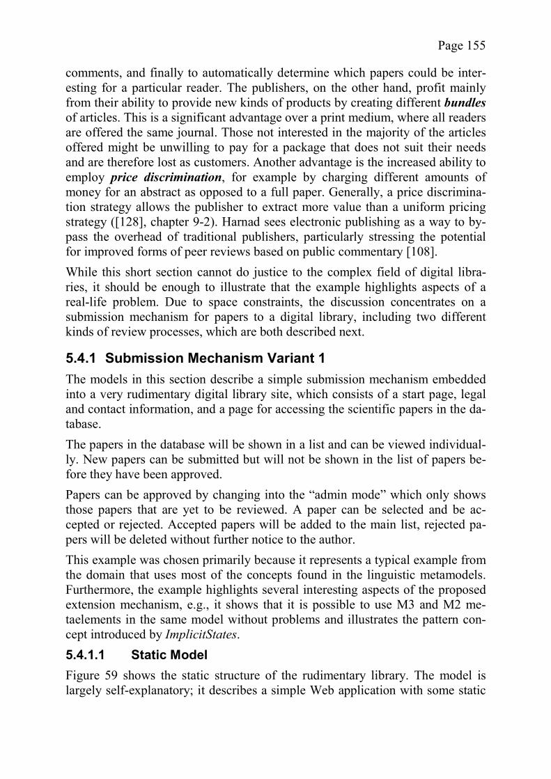
Page 155
comments, and finally to automatically determine which papers could be inter-esting for a particular reader. The publishers, on the other hand, profit mainly from their ability to provide new kinds of products by creating different bundlesof articles. This is a significant advantage over a print medium, where all readers are offered the same journal. Those not interested in the majority of the articles offered might be unwilling to pay for a package that does not suit their needs and are therefore lost as customers. Another advantage is the increased ability to employ price discrimination, for example by charging different amounts of money for an abstract as opposed to a full paper. Generally, a price discrimina-tion strategy allows the publisher to extract more value than a uniform pricing strategy ([128], chapter 9-2). Harnad sees electronic publishing as a way to by-pass the overhead of traditional publishers, particularly stressing the potential for improved forms of peer reviews based on public commentary [108]. While this short section cannot do justice to the complex field of digital libra-ries, it should be enough to illustrate that the example highlights aspects of a real-life problem. Due to space constraints, the discussion concentrates on a submission mechanism for papers to a digital library, including two different kinds of review processes, which are both described next.
5.4.1 Submission Mechanism Variant 1 The models in this section describe a simple submission mechanism embedded into a very rudimentary digital library site, which consists of a start page, legal and contact information, and a page for accessing the scientific papers in the da-tabase. The papers in the database will be shown in a list and can be viewed individual-ly. New papers can be submitted but will not be shown in the list of papers be-fore they have been approved. Papers can be approved by changing into the “admin mode” which only shows those papers that are yet to be reviewed. A paper can be selected and be ac-cepted or rejected. Accepted papers will be added to the main list, rejected pa-pers will be deleted without further notice to the author. This example was chosen primarily because it represents a typical example from the domain that uses most of the concepts found in the linguistic metamodels. Furthermore, the example highlights several interesting aspects of the proposed extension mechanism, e.g., it shows that it is possible to use M3 and M2 me-taelements in the same model without problems and illustrates the pattern con-cept introduced by ImplicitStates. 5.4.1.1 Static Model Figure 59 shows the static structure of the rudimentary library. The model is largely self-explanatory; it describes a simple Web application with some static
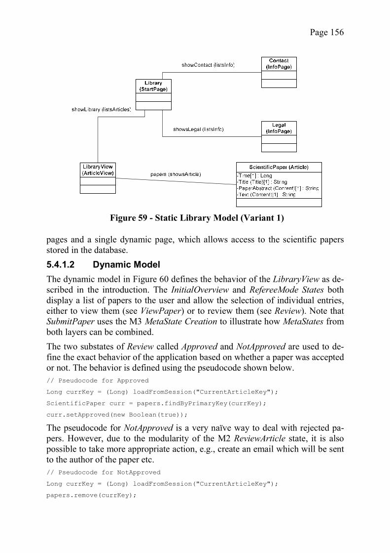
Page 156
pages and a single dynamic page, which allows access to the scientific papers stored in the database. 5.4.1.2 Dynamic Model The dynamic model in Figure 60 defines the behavior of the LibraryView as de-scribed in the introduction. The InitialOverview and RefereeMode States both display a list of papers to the user and allow the selection of individual entries, either to view them (see ViewPaper) or to review them (see Review). Note that SubmitPaper uses the M3 MetaState Creation to illustrate how MetaStates from both layers can be combined. The two substates of Review called Approved and NotApproved are used to de-fine the exact behavior of the application based on whether a paper was accepted or not. The behavior is defined using the pseudocode shown below. // Pseudocode for Approved
Long currKey = (Long) loadFromSession("CurrentArticleKey");
ScientificPaper curr = papers.findByPrimaryKey(currKey);
curr.setApproved(new Boolean(true));
The pseudocode for NotApproved is a very naïve way to deal with rejected pa-pers. However, due to the modularity of the M2 ReviewArticle state, it is also possible to take more appropriate action, e.g., create an email which will be sent to the author of the paper etc. // Pseudocode for NotApproved
Long currKey = (Long) loadFromSession("CurrentArticleKey");
papers.remove(currKey);
Figure 59 - Static Library Model (Variant 1)
Page 157
5.4.2 Submission Mechanism Variant 2 The second example in this section also models a submission mechanism. Its main purpose is to show that the domain-specific metamodels are not too restric-
Figure 60 - Dynamic Library Model (Variant 1)
Figure 61 - Static Library Model (Variant 2)
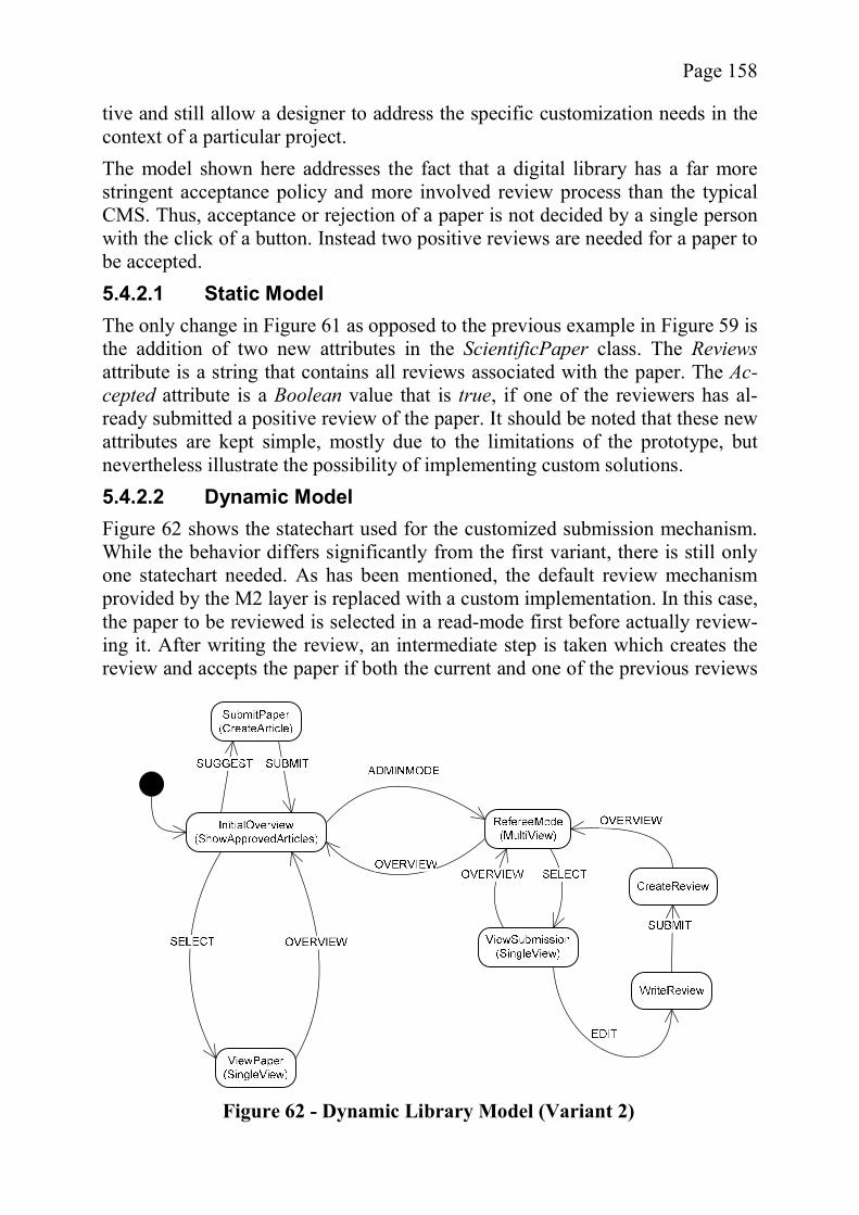
Page 158
tive and still allow a designer to address the specific customization needs in the context of a particular project. The model shown here addresses the fact that a digital library has a far more stringent acceptance policy and more involved review process than the typical CMS. Thus, acceptance or rejection of a paper is not decided by a single person with the click of a button. Instead two positive reviews are needed for a paper to be accepted. 5.4.2.1 Static Model The only change in Figure 61 as opposed to the previous example in Figure 59 is the addition of two new attributes in the ScientificPaper class. The Reviewsattribute is a string that contains all reviews associated with the paper. The Ac-cepted attribute is a Boolean value that is true, if one of the reviewers has al-ready submitted a positive review of the paper. It should be noted that these new attributes are kept simple, mostly due to the limitations of the prototype, but nevertheless illustrate the possibility of implementing custom solutions. 5.4.2.2 Dynamic Model Figure 62 shows the statechart used for the customized submission mechanism. While the behavior differs significantly from the first variant, there is still only one statechart needed. As has been mentioned, the default review mechanism provided by the M2 layer is replaced with a custom implementation. In this case, the paper to be reviewed is selected in a read-mode first before actually review-ing it. After writing the review, an intermediate step is taken which creates the review and accepts the paper if both the current and one of the previous reviews
Figure 62 - Dynamic Library Model (Variant 2)
Page 159
were positive. The pseudocode for WriteReview represents a customized Web form that allows a reviewer to accept or reject a paper and to write a short review about it. // Pseudocode for WriteReview
Map data = (Map) param;
Long key = new Long((String) data.get("instance"));
String[] answers = {"yes", "no"};
createSelectInput(
"Do you think this paper should be accepted for the online Library?",
answers, 0);
createTextAreaInput("Please briefly state the reasons for your decision:",
"");
createHiddenField("instance", key.toString());
The pseudocode for CreateReview is slightly more complex. It describes the be-havior explained above with most of the code representing the extraction of in-formation from the Web form. // Pseudocode for CreateReview
Map data = (Map) param;
Long key = new Long((String) data.get("instance"));
ScientificPaper paper = papers.findByPrimaryKey(key);
Boolean accept = null;
String acc = (String) data.get("Do you think this paper should be accepted for the online Library?");
if (acc.equals("yes")) accept = new Boolean(true);
else accept = new Boolean(false);
String remarks = (String) data.get("Please briefly state the reasons for your decision:");
if (paper.getAcceptance().booleanValue() && accept.booleanValue())
{
// this is the second acceptance
paper.setApproved(new Boolean(true));
}
else
{
paper.setAcceptance(accept);
}
String allReviews = paper.getReviews();
allReviews = allReviews.concat("\n\n"+remarks);
paper.setReviews(allReviews);
While the pseudocode of this example is slightly more complex than the one in the first submission mechanism, it is still quite simple compared to the code re-
Page 160
quired to program the same application from scratch, even when using the same framework. In fact the code generated for the example above is more than 25 pages long, excluding the deployment descriptors3.
5.5 Summary In this chapter, the extension mechanism based on the OMEGA and OMEGA/Dynamic metamodel hierarchies has been introduced. While technical details are omitted, its core features were shown, in particular, the ability to add hierarchical metainformation to all elements in a model. To illustrate the functionality of the extension mechanism, both dynamic and static metamodels from the Web application domain were designed and ex-tended for the CMS subdomain. For the prototype, also examined in this chap-ter, a Web domain code generator module was implemented and extension tem-plates for the CMS subdomain were developed. The prototype was used to create two model fragments describing variants of a paper submission mechan-ism for a scientific online journal. The two fragments will be used as core ex-amples for the evaluation process in the next chapter.
3 See http://www.wifo.uni-mannheim.de/~gitzel/research/OMEGA/SecondExample.pdf

Page 161
6 Conclusions and Future Work Having presented the concepts of the hierarchical extension mechanism for UML and the prototypical code generation environment used for its evaluation, there are only a few issues left to address. First, the example fragments de-scribed in the previous chapter will be used for a critical evaluation of the ex-tension mechanism. Using a list of criteria, it will be shown that the extension mechanism enables a reduction of the overall software development cost in a domain by pointing out particular aspects of the example implementation. It will be examined whether the prototype contains all the crucial elements of a full implementation, in order to show the general applicability of the cost reduction potentials identified. In section 6.2, the OMEGA approach as a whole is critically assessed, discuss-ing aspects which have provoked differing views during discussion at confe-rences or seminars. After that, related and future work will be discussed before providing a brief conclusion.
6.1 Theoretical and Practical Evaluation In order to judge the quality of the proposed extension mechanism, its prototype has to be tested to determine whether the goal defined for the extension mechan-ism is reached. As has been mentioned in the introduction, this goal is the reduc-tion of the total cost of all projects conducted in a specific domain as opposed to the same software implemented based on a custom-developed domain tool. Going back to Figure 1, it can be seen that the total cost consists of two factors; the fixed cost involved in the creation of and training with the tool environment and the cost per project. While the Figure is a simplification, in particular with regard to the linear cost development per project, the model is a suitable basis for an evaluation of the prototype, since the variable costs are not relevant for the comparison (see section 6.1.3). The remainder of this section is structured as follows. First, the approach used for the evaluation of the prototype is described and care is taken to explain why its results are considered representative of the general case. Next, it is shown why the example described in sections 5.2 through 5.4 can be used as a basis for the chosen approach. In section 6.1.3, the concrete realization of the chosen evaluation technique is described. Based on these foundations, the results are presented and explained afterwards.
6.1.1 Evaluation Approach There are several types of software engineering research validation, ranging from “blatant assertion” to formal analysis (cf. Shaw [192], in particular Table 5). However, since no statistically significant body of data provided by experi-ments using the prototype exists yet or can be produced in the context of this
Page 162
work, most of these methods are not applicable. For these reasons, the “’slice of life’ example based on a real system” approach is adopted here ([192], pg. 732). Shaw states that an example can be used to validate research if it represents a realistic instance of the problem which contains all relevant aspects [192]. It can be argued that this reasoning implies that the scalability of the example to real-life problems has to be considered as well even though it is not mentioned expli-citly. For the concrete reasoning about the example, several ideas proposed by Schweiggert are adopted. Schweiggert suggests the identification of a list of cri-teria, starting with the defined goal and iteratively partitioning the criteria fur-ther until they can be used to establish a collection of precise questions whose answer does not depend primarily on personal opinion. The answers to the ques-tions provide a good basis for the validation of the example [185]. In order to be able to apply the advice given by Shaw and Schweiggert, the evaluation approach will be divided into two steps. First, it is shown that the ex-ample is both scalable and representative of the general case. In the second step, a list of criteria is developed and applied to the example.
6.1.2 Scalability and General Applicability of the Example If the example is to be considered adequate for the purposes of the evaluation, it has to be scalable and generally applicable. In this context, both the prototype and the example models have to meet these requirements because it is the com-bination of the two that influences the results of the evaluation. The prototype, while being limited to a subset of the required functionality, only leaves out features which have been shown to work by other researchers. For example, automatic constraint checking is trivial but time-consuming to imple-ment. Similarly, the missing code generation features such as multi-valued attributes are part of other code generators, e.g., those based on Executable UML or the work of Harel and Gery [105]. Therefore, the prototype can be con-sidered scalable and generally applicable based on other, real-world examples. Same arguments apply to the submission mechanism example. The example can be considered a good representation of the general case, because it contains both dynamic and static aspects, which will be encountered in real life and uses all of the aspects newly introduced due to the extension mechanism. For these reasons, other examples will be, in principle, variations using the same elements as the paper submission example. In the light of these arguments the example can be considered generally applicable for the purpose of the evaluation. The scalability of the example can be assumed, if it can be interpreted as a sub-system of a more complex project. Since a subsystem consisting of a class dia-gram and statecharts can be linked with other subsystems using the techniques presented in the Executable UML context, larger applications can be generated
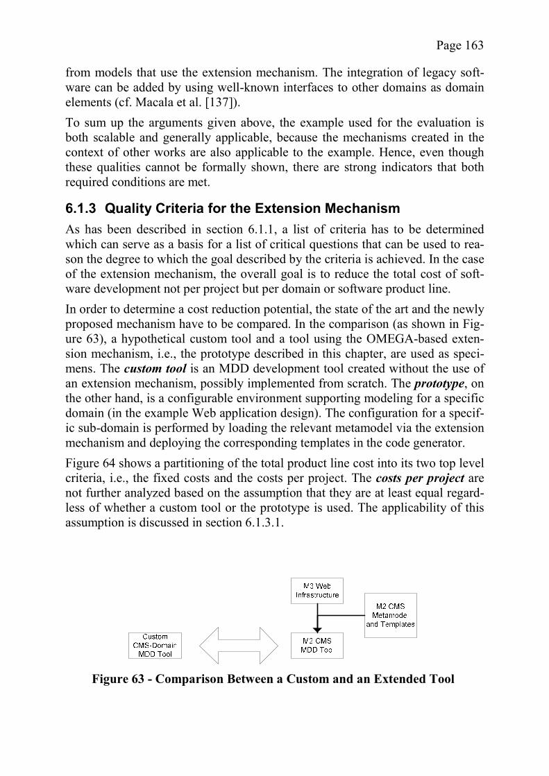
Page 163
from models that use the extension mechanism. The integration of legacy soft-ware can be added by using well-known interfaces to other domains as domain elements (cf. Macala et al. [137]). To sum up the arguments given above, the example used for the evaluation is both scalable and generally applicable, because the mechanisms created in the context of other works are also applicable to the example. Hence, even though these qualities cannot be formally shown, there are strong indicators that both required conditions are met.
6.1.3 Quality Criteria for the Extension Mechanism As has been described in section 6.1.1, a list of criteria has to be determined which can serve as a basis for a list of critical questions that can be used to rea-son the degree to which the goal described by the criteria is achieved. In the case of the extension mechanism, the overall goal is to reduce the total cost of soft-ware development not per project but per domain or software product line. In order to determine a cost reduction potential, the state of the art and the newly proposed mechanism have to be compared. In the comparison (as shown in Fig-ure 63), a hypothetical custom tool and a tool using the OMEGA-based exten-sion mechanism, i.e., the prototype described in this chapter, are used as speci-mens. The custom tool is an MDD development tool created without the use of an extension mechanism, possibly implemented from scratch. The prototype, on the other hand, is a configurable environment supporting modeling for a specific domain (in the example Web application design). The configuration for a specif-ic sub-domain is performed by loading the relevant metamodel via the extension mechanism and deploying the corresponding templates in the code generator. Figure 64 shows a partitioning of the total product line cost into its two top level criteria, i.e., the fixed costs and the costs per project. The costs per project are not further analyzed based on the assumption that they are at least equal regard-less of whether a custom tool or the prototype is used. The applicability of this assumption is discussed in section 6.1.3.1.
Figure 63 - Comparison Between a Custom and an Extended Tool

Page 164
Assuming that the extension mechanism will be used primarily for software de-velopment projects where human resources are the driving cost factor (cf. [22], pg. 74), the fixed costs depend on two major aspects. The first is the time needed for the creation of either the custom tool or the M2 metamodel and templates for the prototype. The second is the time needed to train the development teams how to use the newly created or customized domain-specific tool. 6.1.3.1 Assessing the Variable Costs In order to be able to ignore them, the variable costs have to be identified as in-variant with regard to the environment used. In the simplest model, the costs per project are influenced by the lines of code and the productivity of the developers (cf. [22], pp. 74-75). As the final product is in both cases the same, the lines of code are identical. If it can be argued that the productivity also remains un-changed, the variable costs can be ignored. In effect this means that a tool using the extension mechanism such as the proto-type has to be functionally similar to a tool that has been custom-designed for the same M2 domain. The question to ask in this context is, whether the two tools will appear different to the user or not and if there are any differences, whether they will significantly affect the users ability to create models. It is very likely that a hypothetical custom tool is not fundamentally different to use than the prototype for two reasons. With regard to the graphical user inter-face, the OMEGAPlugin does not look fundamentally different from other mod-eling tools (see Figure 51). Also, as has been shown, it is possible to map the metaelements of the extension mechanism to a UML Profile (see section 5.1.3) and to use the Profile in a standard UML modeling tool. Therefore, there is no fundamental difference between the two cases and no change in variable costs. 6.1.3.2 Assessing the Fixed Costs Due to Time Overhead The general strategy for assessing the fixed costs has already been described. The main intention of the extension mechanism is to greatly reduce the time overhead for the creation of a new domain-specific tool. The questions in this
Figure 64 - Cost Factors
Page 165
context, shown below, examine the degree of reuse made possible due to the ex-tension mechanism.
Is the creation of the M2 metamodel simplified due to the existence of the M3 model?
Is the creation of the M2 templates simplified due to the existence of the M3 templates?
Is the structured reuse made possible by the extension mechanism prefer-able to the ad hoc reuse of templates?
The first two questions were chosen, because they address the two core aspects of the creation of a new MDD tool, assuming that a suitable editor already ex-ists. If it is possible to reuse either model elements or templates of the M3 level, the time overhead for tool creation will be reduced. Yet, if the creation of either is complicated by the requirements of the M3 infrastructure, the overhead will be increased. The last question addresses the fact that there are other forms of reuse as well, i.e., a custom tool can be based on existing templates belonging to related domains which are manually adapted for the new purpose. Regarding the first question, it can be argued that the creation of the M2 meta-model is simplified by the existence of the M3 metamodel. First of all, the exist-ing elements provide guidance for the developer. Since the M3 metamodel can be interpreted as a more abstract view on its M2 metamodels, the basic structure of M2 is already mapped out and it is less likely that elements are forgotten or will be defined poorly. For example, the OMEGA M3 Web application model already contains and enforces for its instances the basic concepts found in both the Web design languages and the COBANA framework with the concepts of dynamic and static views, and navigational contexts realized via Child associa-tions. Besides the guidance provided by the M3 metamodel, in many cases model ele-ments can be reused directly, especially in the case of the dynamic metamodel. The M3 ActionFragments represent common technology-oriented activity of the M3 domain and are therefore essential elements of any domain using the M3 technology. In the example hierarchy, most of the ActionFragments are defined at the M3 level. Their essential contribution to the M2 domain can be seen when looking at the pseudocode of the example models, which makes heavy use of the ActionFragments provided. Model element reuse is less common in the static metamodel. While all elements of the M3 layer are available as metaclasses in the model due to relaxed strict-ness, it is generally advisable to provide specialized M2 metaelements. For ex-ample, the Article metaclass, while not inherently different to the pure DataSet, carries a lot of semantics which can be used in the business logic found in the dynamic M2 models. For instance, the CreateArticle MetaState relies on the ability to interpret the attributes of the persistent data. In particular, the Time-
Page 166
stamp attribute differs from the other attributes, because it is not initialized through user input but automatically assigned the current system time. The Cre-ation MetaState of M3 on the other hand is unable to interpret attributes. Thus, an M2 static metamodel cannot generally reuse many M3 model elements. However, a special situation occurs when a modeled system deviates in some aspects from the intended M2 domain. In that case, the M3 model elements are useful because of their higher level of abstraction. Similarly, the creation of M2 templates is simplified by existence of the M3 me-tamodel and templates. First of all, a high degree of template reuse is possible. In the case of static models, there is a very high potential for reuse. In the exam-ple, no static M2 templates were needed at all, the M3 templates and the ability to weave new attributes into the model being sufficient to generate all static code. While there might be specific cases which do require specialized M2 level templates, it can be assumed that static reuse is generally going to be high. In the case of dynamic models, the saving was more restricted. While some ge-neric M3 MetaStates exist, most behavior is “business logic” and therefore has to be defined at the M2 level. Also, the definition of M2-level implicit Meta-States is not simplified by the existence of the M3 MetaStates. For example, CreateArticle requires a template that does not profit from the existence of simi-lar M3 MetaStates such as Creation, even though conceptually, they seem re-lated. However, the new MetaStates benefit somewhat from the ActionFrag-ments defined at M3 level, because they are realized as methods and can be called by the templates implementing the M2 States. It is hard to give a good estimate of the savings implied by this kind of reuse. However, since the Ac-tionFragments in the example represent basic Web page related activity such as the creation of HTML forms, it is likely that most new MetaStates can reuse code created for the M3 level. The M2 ActionFragments, on the other hand, profit little from the M3 templates in the example. Still, the M2 ActionsFragments were relatively small and more evolved domains are likely to include larger fragments which might use M3-level template code. It is difficult to exactly assess this potential at this stage but since ActionFragments are conceptually similar to MetaStates (e.g., consider showSingleInstance and SingleView) it is likely that a comparable leverage ef-fect will occur. However, artifacts available for reuse as described above only lead to a simplifi-cation, if they are easily incorporated. For example, if reusable code can only be located after a long search, its potential is greatly diminished. In the case of the example hierarchy’s templates, most reuse involves the use of complete tem-plates which are well-defined due to the M3 metamodel. In the more complex cases, the interaction between the layers is largely limited to method calls cor-responding to ActionFragments. The only information that the M2 template pro-
Page 167
grammer needs that is not described in the M3 metamodel is the name of the ba-seclass which implements the M3 ActionFragments. One problem involved in the creation of the M2 templates is that the designers have to know how to implement code for the M3 domain and the details of the technology used for the M3 templates. In the original concept of the code gene-rator, it was intended to transform more or less technology-independent M2 template code to accommodate the technology used at the M3 level using as-pect-oriented programming techniques and weave the resulting fragments into the M3 templates. Since the plan had to be abandoned due to problems with the existing code weaving tools, the deficit as described arises and any attempts to reduce feature delocalization (see section 3.1.2) have to be considered future work. The third question related to the time overhead is essentially whether it is really necessary to use a formalized reuse mechanism instead of simply adapting arti-facts produced in the context of other software product lines. Since this is essen-tially the same question as whether code reuse in general should be formalized or is possible ad hoc, and strong arguments against the latter can be found in the literature (e.g., see Greenfield et al. [102]), the question will be addressed only briefly. In the example, the structured way of reuse provided by the extension mechan-ism is preferable to manually adjusting generic templates, which correspond to the generic M3 Web application templates, to fit the M2 CMS domain. The pri-mary advantage in this context is the maintenance of the templates. Since the M2 templates are largely independent of the M3 templates, interacting only through well-known “interfaces”, the M3 template logic need only be main-tained at a single point instead of for each project. Also, due to the fact that the code generation logic for all transitive instances of an M3 element is concen-trated in a single template, inconsistencies can be avoided. Overall, the extension mechanism seems to hold a great potential for the reduc-tion of the overhead involved in the creation of a new domain-specific modeling tool. It allows a substantial reuse of both templates and model elements, and while at the current stage the technology of the M3 templates has to be unders-tood by the designers working at the M2 level, it is at least theoretically possible to eliminate this problem. 6.1.3.3 Assessing the Fixed Costs due to Initial Training After the creation of a new domain-specific tool, it is necessary to train the de-velopment team in the use of the metamodel and the semantics provided by the templates. The initial training is required for both the custom tool and the proto-type, which can be compared using the following questions.
Is a generic tool more difficult to use than a custom tool?
Page 168
Is the training time reduced by the existence of a generic M3 infrastruc-ture?
Both questions seem to overlap slightly but cover different aspects newly intro-duced by the prototype. Since a generic tool has to cover more than a particular domain, it is possible that this additional requirement makes the tool more diffi-cult to understand. The second question refers to the fact that the generic tool provides a largely uniform interface to the user regardless of domain which might influence the training time. The first questions can be answered briefly. As has been explained in section 6.1.3.1, the prototype’s user interface is not fundamentally different from that of a custom tool. Therefore, the learning effort for both should be the same. For similar reasons, the training time reduction due to the generic infrastructure is minimal or non-existent. Both the custom tools for different domains and the prototype configured for the same domains change by the same degree. The only potential advantage is that all sub-domains of the Web domain will be based on consistent Web principles due to the M3 metamodel, whereas different custom tools might behave inconsistently. As has already been mentioned, the static M3 metaclasses correspond to the concepts found in Web design languages and therefore, all M2 metamodels will be consistent with these concepts. Overall, it can be said that the training cost is not adversely affected by the in-troduction of the extension mechanism. On the other hand, it is questionable whether the training time can be improved significantly.
6.1.4 Explanations and Conclusions In this section, the linguistic metamodels required for the proposed extension mechanism have been validated using an example consisting of a prototypical plugin and an example hierarchy. By analyzing three different criteria, variable cost, creation overhead cost, and training cost, it was shown that the extension mechanism offers a substantial improvement regarding the creation overhead while maintaining the status quo in the other two cases. The findings were sup-ported by examples taken from the prototype and the sample hierarchy. While the benefit due to the reduced overhead cost is substantial, I feel that this is still a very conservative assumption, adopted because of the lack of empirical data. It is my opinion, that there are other areas where the extension mechanism incurs large savings. For example, if it were possible to write domain-independent M2 templates and pseudocode, both the creation of the M2 tem-plates and the training time would be reduced. Also, according to case studies conducted in the past, the quality of the domain-specific tool improves over the time, i.e., with each iteration (cf. Macala et al. [137]). Since all domains reuse M3 templates, the quality of all M2 domains will

Page 169
be improved, reducing the need for maintenance and therefore costs at later stages of the software’s lifecycle.
6.2 General Assessment of the OMEGA Approach While the evaluation in the previous section has shown that the proposed exten-sion mechanism facilitates the creation of new domain-specific MDD modules, there are other aspects, which should at least be briefly addressed. Since in the previous chapters, the different concepts and technologies used for the scientific contributions of this dissertation have already been discussed and the diverse opinions on each subject have been presented, they are not revisited here. In-stead, this section concentrates on those arguments brought forth especially against the OMEGA approach.
6.2.1 Complexity of the Approach At this point, it should be clear that metamodeling is far from trivial. At a super-ficial glance, the concern might arise that the OMEGA approach could be too complex to offer an alternative to manual software development. This feeling is similar to that professed by many critics of MDD approaches, as the following quotation illustrates: “Any technology that deals in meta-meta-models is going to be hard to sell, no matter how many analyst’s reports have been written.” [109] I feel this statement is somewhat misguiding, because it is not important how complex a system is “under the hood”. Indeed, to stay within the analogy, the AFS (Active Front Steering) technology makes driving a car easier and safer, without the user being required to understand the technical details, which are far from simple (cf. [68]). What counts in the end is how complex and reliable the system is to the user. The hierarchical approach described here does not result in complex modeling tasks. In fact, as can be seen in the prototype, the part visible to the user is identical to the stereotype concept of UML. While there are some extra rules, other profiles, such as EDOC, imply similar constraints and thus are as complex as the approach described here (see section 3.5.3.2 for details). Also, section 6.1 suggests that the improved organization and more extensive reuse of code-generation infrastructure made possible by a hierarchical approach will improve reliability in the long run rather then make matters more complex.
6.2.2 The General Layout of the Model Hierarchy The layout of the model hierarchy presented in section 5.2, when seen as the equivalent of the OMG’s refinement process from CIMs to PSMs, features a notable deviation by placing the technology layer at the top. It might be argued that this arrangement is problematic because of the life expectancy of technolo-gy as opposed to that of business logic. In other words, if the technology of the
Page 170
uppermost layer becomes obsolete, so will all of its instances. Therefore, the layer arrangement will reduce the potential of reuse. However, the comparison to the MDA model transformation stages is proble-matic. In particular, the PSMs of the OMG are not instances of the PIMs. Ra-ther, a model transformation is needed to get from the PIM to the PSM. Also, the PIM is the main point of input from the designer, whereas the M3 layer is not edited by an end user. Thus, a PIM and a M3 metamodel are unrelated con-cepts. The argument that the M3 layer relies on a specific technology is only partially true and not as critical as it might seem. Indeed, the technological concepts found on the M3 layer of the OMEGA and OMEGA/Dynamic hierarchies are very abstract. They are not tied to a certain technology but rather to a paradigmsuch as that of the Web, putting them somewhere between MDA’s PIMs and PSMs with regard to level of abstraction (cf. the detailed example given in [133]). On this level of abstraction, there is still a choice whether to generate code for Servlet-based applications or PHP scripts, as well as a choice whether to use HTML, WAP, or some future format yet to be defined. Should the basic paradigm become obsolete, it is still possible to switch to another metamodel by using transformation rules which shift instances from the current metamodel to the new one. Granted, this task is not trivial but with the advent of transforma-tion languages, it will be feasible with reasonable effort. Indeed, the OMG’s MDA reference document explicitly mentions PIM to PIM and PSM to PSM transformations (see [141], pg. 13). However, it is also debatable whether the life expectancy of a technology, espe-cially a technological paradigm, really is a critical factor. Not everybody agrees on the concept that technology is in constant flux (see section 3.3.2.1). In fact, the target groups for OMEGA are Small and Medium-sized Enterprises (SME) which act as “software factories”, producing and maintaining many variations of their basic product. In such a setting, a technology layer at the bottom would be a terrible mistake. It has been argued that a change at a higher model layer re-quires changes at all lower layers. Thus, with the domain layer above the tech-nology layer, each problem domain would need its own technology templates, even if all projects were intended for the same technological target platform. This situation is the exact opposite of the intentions associated with the hierar-chical extension mechanism.
6.2.3 Conceptual Issues One aspect of the OMEGA ontological metamodel that has caused other re-searchers in the same field to pronounce their disagreement is the definition of instantiation as transitive. In particular, the concern was raised that this would make instantiation indistinguishable from inheritance. Similarly, any of the other deviations from the established metamodeling rules could lead to comparable discussions.
Page 171
It is true that some of the definitions and concepts have been changed and that a metamodeling purist can locate aspects where the definitions used in this disser-tation run counter to some previously established ones. However, the linguistic metamodels described are an extension of existing concepts and the deviations are not methodological mistakes but intentional modifications, identified as such. The concern of a lack of distinction between inheritance and transitive instantia-tion to me seems to be unwarranted, especially in the light of the delimitation provided in section 3.5. Maybe the problem is that to its opponents, transitive instantiation is closer to inheritance than to their (non-transitive) concept of in-stantiation. However, as the proverb goes: “What’s in a name?” As the evalua-tion of the prototype has shown, the extension mechanism does provide an im-provement over the existing extension mechanisms because it allows the reuse of more abstract domains. This improvement is independent of the names used to describe the concepts. Therefore, any discussion in this context is purely aca-demic.
6.3 Open Questions and Future Work As shown in the previous section, the open details found in the extension me-chanism have already been discussed elsewhere (e.g., in section 5.1.1.6) and the discussion of future work at this point will be limited to the conceptual level. While a lot of work has been put into both the theoretical foundation and the ac-tual prototype, there were still areas too specific to individual aspects of the problem or too labor-intensive to be fully addressed. The example hierarchy provided for the evaluation of the extension mechanism is one of the aspects that could profit from future work. Domain specific lan-guages of any kind are difficult to come up with and have to be improved itera-tively (cf. Völter [209] and Macala et al. [137]). Since the Web application hie-rarchy used was only for illustrative purposes and has not seen a lot of use, it should be clear that it might need further refinement and expansions. Indeed, this problem is a result of the fact that the whole approach could not be tested extensively in the context of this work, in particular in the context of an empirical evaluation based on real-life Web projects. It would be interesting to see which of the inherent benefits of the approach would be perceived as most useful by practitioners and what further development paths would be discovered. However, before such an evaluation could be conducted, many of the tool’s modules would have to be improved. In particular, the code generation me-chanisms were mostly neglected, since the goal of this dissertation was not to improve code generation algorithms, but to improve the input given to them. Aspect-oriented code weavers such as Inject/J [69] developed at the For-schungszentrum Informatik (FZI) in Karlsruhe would complement the concepts found in the metamodel hierarchy nicely. At the current stage, InjectJ in particu-
Page 172
lar still lacks a few key capabilities, such as metadata input, making integration into the OMEGA plugin an interesting target of future work. Finally, not all aspects of the metamodel hierarchies have a formal definition. OMEGA/Dynamic has not been formally documented in the same detail as the original OMEGA metamodel. The main reason is that OMEGA/Dynamic is a metamodel which departs from the other hierarchies typically found in the litera-ture and it is therefore necessary to define all constraints from scratch. For the same reason, the model was prone to changes and testing its capabilities was deemed more important than formally defining its technical details. Overall, the ideas presented in this dissertation are limited to a very specific as-pect of MDD and it is surprising how many different ideas, standards, and even fields of research had to be considered to propose an improved variant. In some ways, the work completed felt like fundamental research in so far as many infra-structural tools were developed. Hopefully, at least some of the software com-ponents created for the prototype will enable others to build upon the ideas pre-sented here.
6.4 Related Work Since the ideas proposed in this dissertation come from a very active field of re-search which rejuvenates many ideas of its predecessors and overlaps with other fields, it is a difficult decision which publications to consider as related. Also, many of the individual chapters already present related work, e.g., chapter 4 dis-cusses other MDD efforts in the domain of Web applications. The primary goal of this dissertation was identified as the proposal of a new ex-tension mechanism for UML. Therefore, it might be prudent to limit related work to UML extension mechanisms only. However, these approaches have been discussed in detail in section 3.5. More importantly, there are other projects which have the same purpose as the extension mechanism described in this dis-sertation, which should also be considered in this context. Therefore, the discussion of related work focuses on any kind of tool or software development process which aims at providing an infrastructure to rapidly estab-lish domain-specific code generation environments. As has been mentioned, a lot of the other work referenced throughout the chapters could be considered re-lated work, but is not repeated here for space reasons.
6.4.1 UML as a Family of Languages The catchphrase “UML as a family of languages” which applies to the works of Duddy [61], Atkinson and Kühne [17], Völter [208], Nordstrom ([154], [155]), Frankel [72], Kent [131], Clark et al. [48] and many others, has already been discussed before. Without going into the details, it can be said that these ap-proaches see UML as a generic extensible language suitable for a wide range of domains. Based on UML’s metametamodel, it is possible to use the same infra-

Page 173
structure to design models for domains which have vastly different or even con-tradictory semantics (cf. Cook [50]), without having to resort to lightweight ex-tension mechanisms such as UML Profiles. A custom metamodel can be used with all the benefits a specialized modeling language offers within a known tool framework. Duddy [61] proposes a vision for MDA where models based on cus-tom metamodels can be designed, then transformed to a PSM common to all me-tamodels to use for code generation. Some of the “family of languages” approaches are very similar to the ideas pro-posed in this work, in particular those using a nonlinear hierarchy. However, the OMEGA-based extension mechanism expands those concepts, introducing a static and a dynamic hierarchy for metamodel elements. The related work here often stays closer to the original UML concepts even in aspects that will be transparent for the end user, therefore not requiring such a conservative ap-proach.
6.4.2 Software Product Lines The concept of domain-specific, product-line software development can be considered to be a precursor of some of the ideas presented here. Its core idea is that domain-specific infrastructures are created in a separate development process to be used as an infrastructure for software development within a specif-ic domain (cf. [137]). However, this approach lacks a focus on modern stan-dards, thus providing no base-line infrastructure for the creation of new domain tools. In fact, in the case study by Macala et al. [137], the analysis which toolswill be required is considered to be a vital step. In the OMEGA-based prototype, the infrastructure is fixed and only the domain-specific information has to be developed.
6.4.3 MetaCASE Tools The idea of providing an infrastructure for a code generation environment is al-so not new; an early example is the metaCASE concept. In his review of meta-CASE tools, Isazadeh identifies the labor-intensity involved in the creation of CASE tools as a major problem, warranting the use of tools which allow the au-tomatic generation of CASE tools as a solution. While metaCASE tools seem to offer many advantages over traditional CASE tools, they lack good metamodel languages for the creation of modeling languages to be used in the CASE tools [122]. There are two major differences between the metaCASE concept and the OMEGA prototype. First, the metaCASE tools do not produce domain-specific tools but rather tools that are centered on a specific software development me-thodology or process. In contrast, OMEGA’s prototype is not tied to a specific software process. Instead, its extension mechanism focuses on the hierarchical creation of domain-specific languages. Second, the core problem of metaCASE
Page 174
tools, the poor quality of the metamodeling language, is avoided by using a va-riant to the well-established MOF standard as metamodel.
6.4.4 Software Factories Among all the related work, Software Factories come closest to the OMEGA approach described in this dissertation. Greenfield et al. describe this vision of the future of software development in their book of the same title [102]. Briefly speaking, Software Factories are a specialized form of software product lines. Greenfield et al. aim at defining an infrastructure of concepts that allows the fast and professional development of a software factory schema, a general analysis of a problem domain (e.g., financial services or health care). The sche-ma consists of several viewpoints and their relationships to each other. Each viewpoint is associated with certain artifacts such as models or code and the re-lationships show the required synchronization in the case of changes. Based on the schema, a set of tools, domain-specific modeling languages, frameworks, patterns, and processes can be developed which can then be integrated into a ge-neric IDE to allow the development of a very specific type of product. A product is finished as soon as all the artifacts defined in the schema are implemented or generated. The goal of the software factory concept is to maximize the amount of reuse by creating a synthesis of existing concepts such as development by assembly, model-driven development, or process frameworks. Its progenitors hope that this approach will lead to component standards, which in turn lead to the emergence of software supply chains and ultimately a mass customization of software. While the approach shares many similarities with OMEGA, especially the con-cept of using suitable domain-specific frameworks as a basis for code genera-tion, its scope is far wider and its solutions differ in important details. For exam-ple, Software Factories’ MDD concepts are elaborationist, requiring a (possibly manual) synchronization of different artifacts such as models and code. This sit-uation cannot occur in OMEGA, due to its translationist nature. Also, most of the effort put into OMEGA focuses on the improvement of UML’s extension mechanism, rather than sharing the wider scope of the software factory ap-proach.
6.5 Conclusion As stated in chapter 1, the main objective of this dissertation is to provide a hie-rarchical extension mechanism for UML which allows for a more efficient de-velopment of code generation modules for a specific domain. The mechanism was evaluated using a prototypical code generation environment using a prob-lem domain suitable for MDD, in this case, Web applications. Secondary scientific contributions were the creation of a design space covering the options of metamodeling hierarchy creation, a critical analysis of the goals
Page 175
as well as the state of the art of MDD, and the analysis of the Web application domain to determine its suitability for MDD. By analyzing several different criteria, it was shown that the extension mechan-ism offers a substantial improvement regarding the creation overhead of do-main-specific tools while at least maintaining the status quo in the other two cases. The findings were supported by examples taken from the prototype and the sample hierarchy. The evaluation results show that the proposed extension mechanism is an inter-esting avenue for the improvement of contemporary software development. Since it nicely integrates with existing MDD-related standards, it is not a purely academic exercise but has practical relevance, offering a systematic solution that might help domestic SME software developers to stay competitive against off-shore competition.
Page 176
Appendix A: OMEGA Constraints This appendix formally describes the model elements and constraints in the OMEGA linguis-tic metamodel. The elements are grouped by type and the constraints are listed at the end.
Changed Classes In this section, the changes made to the existing classes of the original MOF metamodel are described. For reasons of brevity, I only describe the actual changes and not the whole classes.
Classifier
Super Classes Instance GeneralizableElement
Constraints
Class
Constraints
Attribute
Super Classes Instance StructuralFeature MetaElement
Constraints
Association
Constraints
Package While Package has not been changed in any way, it is included here, because OMEGA looks for a tag named ValidationTag in the outermost Package. If such a tag does not exist, the software will check whether the model complies to the constraints defined for the ontological hierarchy and include the tag with a value of true if the model is valid and false otherwise. If the tag exists, a check will only be performed if its value is false and it will be updated accor-dingly.
New Classes
Page 177
These classes are new additions to the MOF metamodel which allow the modeling of meta-model hierarchies. Their position in the class hierarchy can be seen in Figure 26.
ModelLayer A model layer contains all elements of a single ontological level. Its use is not enforced by any kind of constraints. However, it can vastly help the understanding of a hierarchy and also can be used to provide "frozen” metalayers for a model.
Super Classes Package Instance MetaElement
Contained Elements MetaClass, Class, Association, MetaAssociation, MetaAttribute, Exception, Constant, Con-straint, Tag, DataType
Attributes None.
References None.
Operations None.
Constraints
MetaElement This class has been introduced to allow for a single InstanceOf relationship as opposed to sev-eral different ones. Due to this fact, MetaElement does not really have any properties at all save for the fact that it can be used as a target for the InstanceOf relationship. In this respect it is not so much unlike the GeneralizableElement for inheritance. isAbstract = true
Super Classes None
Contained Elements None
Attributes canSpawnMeta:boolean. If true, instances of this MetaElement can be MetaElements
as well.
References None
Operations
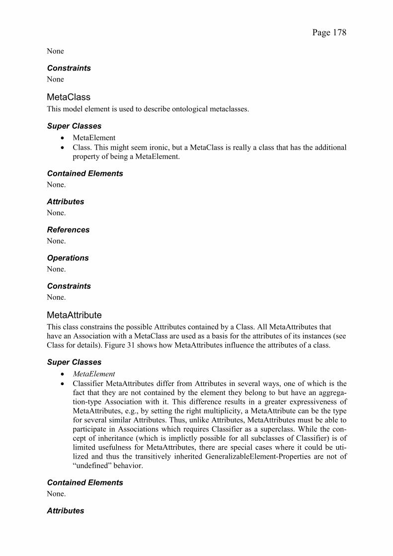
Page 178
None
Constraints None
MetaClass This model element is used to describe ontological metaclasses.
Super Classes MetaElement Class. This might seem ironic, but a MetaClass is really a class that has the additional
property of being a MetaElement.
Contained Elements None.
Attributes None.
References None.
Operations None.
Constraints None.
MetaAttribute This class constrains the possible Attributes contained by a Class. All MetaAttributes that have an Association with a MetaClass are used as a basis for the attributes of its instances (see Class for details). Figure 31 shows how MetaAttributes influence the attributes of a class.
Super Classes MetaElement Classifier MetaAttributes differ from Attributes in several ways, one of which is the
fact that they are not contained by the element they belong to but have an aggrega-tion-type Association with it. This difference results in a greater expressiveness of MetaAttributes, e.g., by setting the right multiplicity, a MetaAttribute can be the type for several similar Attributes. Thus, unlike Attributes, MetaAttributes must be able to participate in Associations which requires Classifier as a superclass. While the con-cept of inheritance (which is implictly possible for all subclasses of Classifier) is of limited usefulness for MetaAttributes, there are special cases where it could be uti-lized and thus the transitively inherited GeneralizableElement-Properties are not of “undefined” behavior.
Contained Elements None.
Attributes
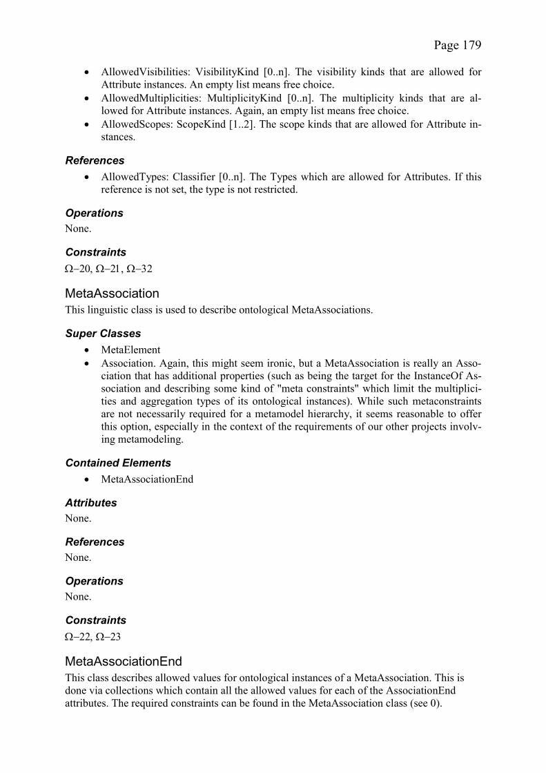
Page 179
AllowedVisibilities: VisibilityKind [0..n]. The visibility kinds that are allowed for Attribute instances. An empty list means free choice.
AllowedMultiplicities: MultiplicityKind [0..n]. The multiplicity kinds that are al-lowed for Attribute instances. Again, an empty list means free choice.
AllowedScopes: ScopeKind [1..2]. The scope kinds that are allowed for Attribute in-stances.
References AllowedTypes: Classifier [0..n]. The Types which are allowed for Attributes. If this
reference is not set, the type is not restricted.
Operations None.
Constraints
MetaAssociation This linguistic class is used to describe ontological MetaAssociations.
Super Classes MetaElement Association. Again, this might seem ironic, but a MetaAssociation is really an Asso-
ciation that has additional properties (such as being the target for the InstanceOf As-sociation and describing some kind of "meta constraints" which limit the multiplici-ties and aggregation types of its ontological instances). While such metaconstraints are not necessarily required for a metamodel hierarchy, it seems reasonable to offer this option, especially in the context of the requirements of our other projects involv-ing metamodeling.
Contained Elements MetaAssociationEnd
Attributes None.
References None.
Operations None.
Constraints
MetaAssociationEnd This class describes allowed values for ontological instances of a MetaAssociation. This is done via collections which contain all the allowed values for each of the AssociationEnd attributes. The required constraints can be found in the MetaAssociation class (see 0).
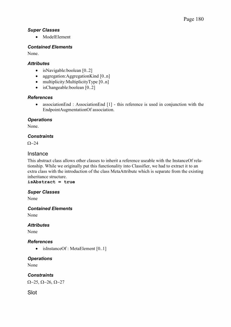
Page 180
Super Classes ModelElement
Contained Elements None.
Attributes isNavigable:boolean [0..2] aggregation:AggregationKind [0..n] multiplicity:MultiplicityType [0..n] isChangeable:boolean [0..2]
References associationEnd : AssociationEnd [1] - this reference is used in conjunction with the
EndpointAugmentationOf association.
Operations None.
Constraints
Instance This abstract class allows other classes to inherit a reference useable with the InstanceOf rela-tionship. While we originally put this functionality into Classifier, we had to extract it to an extra class with the introduction of the class MetaAttribute which is separate from the existing inheritance structure. isAbstract = true
Super Classes None
Contained Elements None
Attributes None
References isInstanceOf : MetaElement [0..1]
Operations None
Constraints
Slot
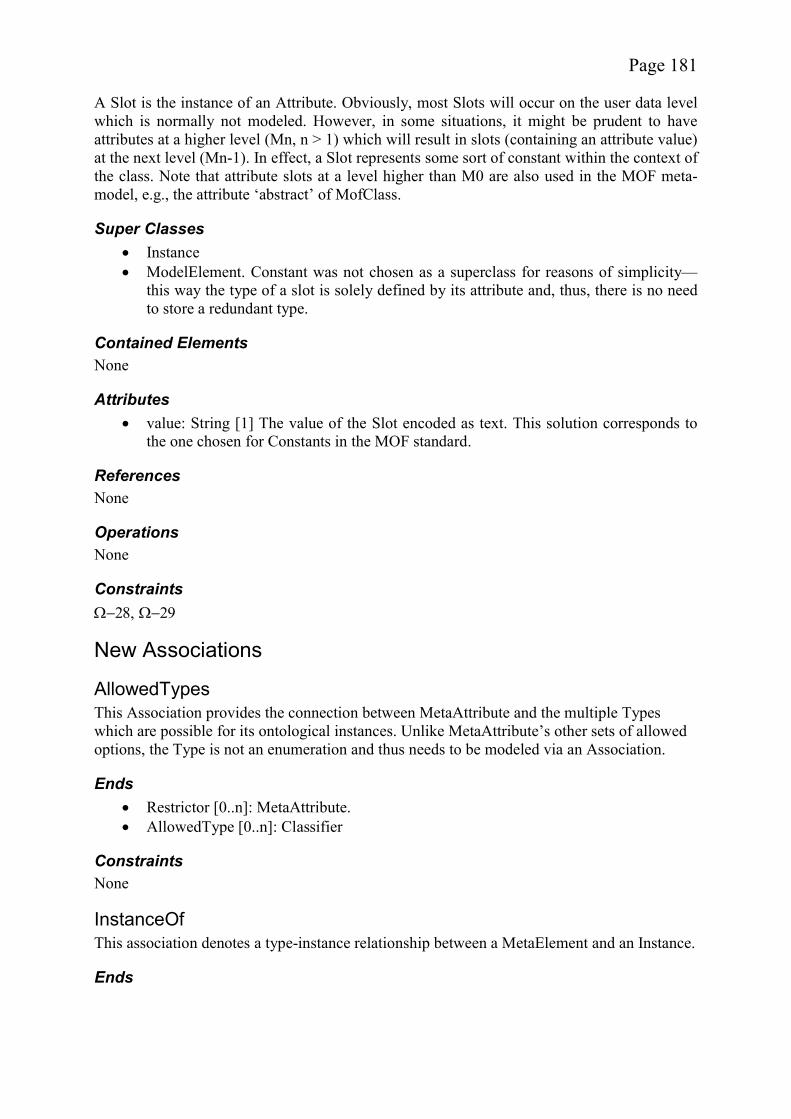
Page 181
A Slot is the instance of an Attribute. Obviously, most Slots will occur on the user data level which is normally not modeled. However, in some situations, it might be prudent to have attributes at a higher level (Mn, n > 1) which will result in slots (containing an attribute value) at the next level (Mn-1). In effect, a Slot represents some sort of constant within the context of the class. Note that attribute slots at a level higher than M0 are also used in the MOF meta-model, e.g., the attribute ‘abstract’ of MofClass.
Super Classes Instance ModelElement. Constant was not chosen as a superclass for reasons of simplicity—
this way the type of a slot is solely defined by its attribute and, thus, there is no need to store a redundant type.
Contained Elements None
Attributes value: String [1] The value of the Slot encoded as text. This solution corresponds to
the one chosen for Constants in the MOF standard.
References None
Operations None
Constraints
New Associations
AllowedTypes This Association provides the connection between MetaAttribute and the multiple Types which are possible for its ontological instances. Unlike MetaAttribute’s other sets of allowed options, the Type is not an enumeration and thus needs to be modeled via an Association.
Ends Restrictor [0..n]: MetaAttribute. AllowedType [0..n]: Classifier
Constraints None
InstanceOf This association denotes a type-instance relationship between a MetaElement and an Instance.
Ends
Page 182
Level [0..n]: Instance, not navigable. The reason for the non-navigability is that the meta element will most likely be frozen and thus cannot have a changeable reference corresponding to this association.
Metalevel [0..1]: MetaElement
Constraints
EndpointAugmentationOf This association connects a MetaAssociationEnd and an AssociationEnd. The MetaAssocia-tionEnd provides rules which restrict the instance of the endpoint corresponding to the Assoc-iationEnd.
Ends MetaInfo [0..1]: MetaAssociationEnd, not navigable. Endpoint [1]: AssociationEnd. Every MetaAssociationEnd is associated with exactly
one AssociationEnd.
Constraints None
Constraints Given the set A of all Associations and MetaAssociations associated with a class C,
and given a set A’ of all MetaAssociations associated with its MetaClass C’, the fol-lowing must be true: For each x A there must be an x’ A’ which is the Me-taElement of x. The other restrictions imposed on Associations are enforced in the Association class and the multiplicities are enforced by .
Given the set A of all Attributes contained in and all MetaAtributes associated with a class C, and given a set A’ of all MetaAttributes associated with its MetaClass C’, the following must be true: For each x A there must be an x’ A’ which is the MetaElement of x. Furthermore, for each x’ A’ the number of elements in A which are its instances must be higher or equal to the minimum multiplicity and lower or equal to the maximum multiplicity of the Association which connects x’ to C’. This constraint can be easily implemented by using a hashmap with the MetaElements as keys and the (Meta)Attributes as values.
The Slots a Class C contains depend on its MetaClass C’ (as identified by isInstan-ceOf). For each attribute contained in C’, C must contain exactly one Slot which is an instance of the Attribute. Attributes differ from MetaAttributes in many ways; one of them is the fact that they are actually contained in a Class as opposed to having a “composite” Association with it.
Each Class that is not a MetaClass must participate in exactly one InstanceOf rela-tionship. A MetaClass is also a Class due to inheritance.
Augment rule C-15: A Class may contain only Classes, DataTypes, Attributes, Slots, References, Operations, Exceptions, Constants, Constraints, and Tags.
The properties of an Attribute (e.g., type or visibility) depend on its MetaAttribute (as identified by isInstanceOf). An Attribute must have values for multiplicity, visi-bility, and scope, which are elements in the corresponding lists of allowed values
Page 183
given in the MetaAttribute reachable via the InstanceOf relationship. The type of an attribute must be an InstanceOf one of the elements referenced by AllowedTypes of its MetaAttribute.
Each Attribute A being a Feature of some ModelElement M must participate in ex-actly one InstanceOf relationship with a MetaAttribute A’ being a Feature of some ModelElement M’, for which is true that M has an InstanceOf relationship with M’.
Despite the introduction of MetaAssociation which inherits from Association, Rule C-34 is unchanged. This might seem confusing at the first glance as the rule states that Associations may not have subclasses. However, it is important to realize that Association is an instance_of Class and not an instance_of Association!
Augment rule C-33: An Association may only contain AssociationEnds, Constraints, and Tags with "... plus any elements specified by any of its subclasses.". If this rule was not changed, MetaAssociations could not contain MetaAssociationEnds as they inherit C-33 from this class.
If an Association A is an InstanceOf a MetaAssociation A’ (i.e., the reference isIns-tanceOf is set) the attribute values of the AssociationEnds of A must each be an ele-ment of the corresponding set of allowed values found in the MetaAssociationEnds of A’.
Each Association that is not a MetaAssociation must participate in exactly one In-stanceOf relationship. A MetaAssociation is also an Association due to inheritance.
For all Instances contained within a ModelLayer M, the reference isInstanceOf is null if and only if the reference isInstanceOf of M is also null. In other words, only the topmost model layer can contain elements which have no metaelements.
Each ModelLayer must be contained in a package.
A ModelLayer may only contain the following elements: MetaClass, Class, Associa-tion, MetaAssociation, MetaAttribute, Exception, Constant, Constraint, Tag and Da-taType
If a ModelLayer whose reference isInstanceOf is null is contained in a package, no other ModelLayer with a reference isInstanceOf that equals null can be in the same package. This implies that only one topmost model layer can exist in a package.
For all Instances contained within a ModelLayer M, the element referenced by isIns-tanceOf, if any, must be contained in a ModelLayer transitively reachable via M’s isInstanceOf reference. This constraint is less restrictive than it could be—in effect it describes a relaxed form of strictness. It allows metaelement to element relationships to skip model layers altogether, i.e., an element found in O1 may directly instantiate an element from O3.
All linguistic Associations other than InstanceOf which involve elements within this layer must have the other endpoint also within this layer.
For each MetaAssociation A’, the following must hold true: Given the set  of all instances An, nN0, of A’ with the AssociationEnds a1,n (which are instances of Me-taAssociationEnd ma1, referencing AssociationEnd a1’ of A’) and a2,n (which are in-stances of the MetaAssociationEnd ma2 of A’, referencing AssociationEnd a2’ of A’) and the set Ê1 of all instances C1,n of the MetaClass(?) C’1 referenced by isOfType of a1’ and the set Ê2 of all instances C2,n of the MetaClass(?) C’2 referenced by isOf-
Page 184
Type of a2’: For each element C1,n Ê1 the number of opposite elements C2,n Ê2reachable through an association An  must not exceed the lower and upper bound of the AssociationEnd a2’ of the MetaAssociation A’. For each element C2,n Ê2 the number of opposite elements C1,n Ê1 reachable through an association An  must not exceed the lower and upper bound of the AssociationEnd a1’ of the Me-taAssociation A’. This is the standard behaviour expected of the instances of a Me-taAssociation with regard to multiplicities.
The following rule is directly derived from ModelElement’s constraints and thus im-plies: If the layer is frozen, none of the elements within can be changed in any way.
A MetaAttribute can contain Tags and Constraints.
A MetaAttribute, which has an InstanceOf relationship to a MetaAttribute must have values for type, multiplicity, visibility, and scope which are subsets of the corres-ponding lists of allowed values given in the MetaAttribute. If no set is given at the metalevel, any set or no set at all may be used for the instance.
A MetaAssociation can and must contain exactly 2 MetaAssocationEnds in addition to the elements described in C-33.
The Type of all AssociationEnds within a MetaAssocation must be MetaClass or MetaAttribute. MetaElement is not a valid choice, because otherwise MetaAssocia-tions or ModelLayers would be valid endpoints as well.
associationEnd must point to one of the AssociationEnds contained within the Me-taAssociation containing this MetaAssociationEnd. This implies that the Endpoin-tAugmentationOf Association may only connect elements within the same MetaAs-sociation’s namespace.
No Instance, that is also a MetaElement, may be an InstanceOf itself or of any of its Instances.
No Instance, that is also a MetaElement, may be an InstanceOf a MetaElement with canSpawnMeta = false.
No Instance may be an InstanceOf a MetaElement which is a GeneralizableElement and has the linguistic attribute ‘isAbstract’ set to ‘true’. The confusing nature of this constraint results from our desire to ensure backwards compatibility.
‘value’ must contain the textual representation of an attribute value which must be of the type specified by the Attribute reachable via isInstanceOf. It should be noted that this constraint can only be enforced for the built-in primitive types. Arbitrary and complex types cannot be handled in a standardized way.
The name of the Slot must be the same as the name of its MetaElement.
A Class can only be an instance of a MetaClass, an Attribute can only be an instance of MetaAttribute, a ModelLayer can only be an instance of a ModelLayer, an Asso-ciation can only be the instance of a MetaAssociation and a Slot can only be the in-stance of an Attribute.
A MetaClass can only be an instance of a MetaClass, a MetaAttribute can only be an instance of MetaAttribute, and a MetaAssociation can only be the instance of a Me-taAssociation.

Page 185
For each type referenced by the association AllowedTypes, the referenced end, i.e. element must be of type Class or DataType.
Page 186
References [1] Accelerated Technologies (2004): Nucleus Bridgepoint.
http://www.acceleratedtechnology.com/embedded/nuc_modeling.html [2] AndroMDA Community (2004): AndroMDA Homepage. http://www.
andromda.org/ [3] Ali, J. and Tanaka, J. (2000): Converting Statecharts into Java Code.
In: Proceedings of the Fourth & Fifth World Conference on Integrated Design and Process Technology (IDPT 1999-2000), Dallas, Texas, June 4-8, 2000, Society for Design and Process Science (SDPS), CD-ROM
[4] Akehurst, D.H. and Patrascoiu (2003): Tooling Metamodels with Pat-terns and OCL. In: Proceedings of the Metamodelling for MDA Work-shop, York, November 2003, Online Proceedings: http://www.cs.york.ac.uk/metamodel4mda/onlineProceedingsFinal.pdf
[5] Albin, S. (2003): The Art of Software Architecture: Design Methods and Techniques. John Wiley & Sons, New York, online version at Books24x7
[6] Álvarez, J., Evans, A., and Sammut, P. (2001): Mapping between Le-vels in the Metamodel Architecture. In: Gogolla, M. and Kobryn, C. (Editors): Proceedings of the The Unified Modeling Language, Model-ing Languages, Concepts, and Tools, 4th International Conference (UML 2001), Toronto, Canada, October 2001, Lecture Notes in Com-puter Science 2185, Springer Verlag, New York, pp. 34-46
[7] Ambler, S. W. (2002): Agile Modeling: Effective Practices for eX-treme Programming and the Unified Process. Wiley & Sons, New York, online version at Books24x7
[8] Ambler, S. W. (2005): Agile Modelling Homepage. http://www.agilemodeling.com
[9] Apache Software Foundation (2005): Apache Xalan 2.5.2, http://xml.apache.org/xalan-j/
[10] Apache Software Foundation (2005): The Apache Cocoon Project. http://cocoon.apache.org/
[11] Apache Software Foundation (2005): The Apache Struts Web Applica-tion Framework. http://struts.apache.org/
[12] Apache Jakarta Project (2005): Jakarta Tapestry. http://jakarta.apache.org/tapestry/
[13] Apache Jakarta Project (2005): Jakarta Turbine Web Application Framework. http://jakarta.apache.org/turbine/

Page 187
[14] Apache Jakarta Project (2005): Velocity. http://jakarta.apache.org/velocity/
[15] Atkinson, C. and Kühne, T. (2003): Calling a Spade a Spade in the MDA Infrastructure, In: Proceedings of the Metamodelling for MDA First International Workshop, York, UK, November 2003, Online Pro-ceedings: http://www.cs.york.ac.uk/metamodel4mda/onlineProceedingsFinal.pdf
[16] Atkinson, C. and Kühne, T. (2003): Model-Driven Development: A Metamodeling Foundation. In: IEEE Software, September/October 2003 (Vol. 20, No. 5), IEEE, pp. 36-41
[17] Atkinson, C. and Kühne, T. (2002): Rearchitecting the UML Infrastruc-ture. In: ACM Transactions on Modeling and Computer Simulation, October 2002 (Vol. 12, No. 4), pp. 290-321
[18] Atkinson, C. and Kühne, T. (2002): The Role of Metamodeling in MDA. In: Proceedings of the International Workshop in Software Model Engineering (held in conjunction with UML ’02), Dresden, Germany, October 2002. http://www.metamodel.com/wisme-2002/
[19] Atkinson, C. and Kühne, T. (2001): The Essence of Multilevel Meta-modeling. In: Gogolla, M. and Kobryn, C. (Editors): Proceedings of the The Unified Modeling Language, Modeling Languages, Concepts, and Tools, 4th International Conference (UML 2001), Toronto, Canada, October 2001, Lecture Notes in Computer Science 2185, Springer Ver-lag, New York, pp. 19-33
[20] Atkinson, C., Kühne, T., and Henderson-Sellers, B. (2002): Stereotypi-cal Encounters of the Third Kind. In: Jézéquel, J.-M., Hussmann, H., and Cook, S. (Editors): Proceedings of the Unified Modeling Lan-guage, 5th International Conference (UML 2002), Dresden, Germany, October 2002, Lecture Notes in Computer Science 2460, Springer Ver-lag, New York, pp. 100-114
[21] Atkinson, C. (1997): Meta-Modeling for Distributed Object Environ-ments. In: Proceedings of the 1st International Enterprise Distributed Object Computing Conference (EDOC’97), Gold Coast, Australia, Oc-tober 1997, IEEE Computer Society, pp. 90-101
[22] Balzert, H. (2000): Lehrbuch der Softwaretechnik. Spektrum, Akade-mischer Verlag, Heidelberg.
[23] Baresi, L., Garzotto, F., and Paolini, P. (2000): From Web Sites to Web Applications: New Issues for Conceptual Modeling. In: Liddle, S. W., Mayr, H. C., and Thalheim, B. (Eds.): ER 2000 Workshop, LNCS 1921, Springer Verlag, New York, pp. 89-100

Page 188
[24] Barracuda (2002): Surveying the Landscape. http://barracudamvc.org/ Barracuda/docs/landscape.html
[25] Barta, R. and Schranz, M. (2005): JESSICA: an object-oriented hyper-media publishing processor. http://www.ra.ethz.ch/CDstore/ww w7/1882/com1882.htm
[26] Beck, K. and Gamma, E. (2004): Contributing to Eclipse: Principles, Patterns, and Plug-Ins. Pearson Education, 2004
[27] Becker, S. A. and Berkemeyer, A. (2002): Rapid Application Design and Testing of Web Usability. In: IEEE Multimedia, Octo-ber/December 2002 (Vol. 9 No. 4), IEEE Computer Society, pp. 38-46
[28] Becker, S. A. and Mottay, F. E. (2001): A Gobal Perspective on Web Site Usability. In: IEEE Software January/February 2001 (Vol. 18 No. 1), pp. 54-61
[29] Beigbeder, S. M. and Castro, C. C. (2004): An MDA Approach for the Development of Web Applications. In: Koch, N., Fraternali, P., and Wirsing, M. (Eds.): Proceedings of the International Conference on Web Engineering (ICWE 2004), July 2004, Munich, LNCS 3140, Springer-Verlag, New York, pp. 300-305
[30] Bézivin, J. (2003): MDA: From Hype to Hope, and Reality. Invited Talk at the UML 2003, http://www.sciences.univ-nantes.fr/info/perso/ permanents/bezivin/UML.2003/UML.SF.JB.GT.ppt
[31] Bézivin, J. and Lemesle, R. (1998): Ontology-Based Layered Seman-tics for Precise OA&D Modeling. In: J. Bosch, S. Mitchell (Editors): ECOOP'97 Workshop Reader, June 1997, Jyväskylä, Finland, LNCS 1357, Springer Verlag, New York, pp. 151-154
[32] Bézivin, J. and Lemesle, R. (1997): Ontology-Based Layered Seman-tics for Precise OA&D Modeling. In: J. Bosch, S. Mitchell (Editors): ECOOP'97 Workshop Reader, June 1997, Jyväskylä, Finland, LNCS 1357, Springer Verlag, New York, pp.151-154
[33] Bichler, L.: A flexible code generator for MOF-based modeling lan-guages. In: Processings of the 2nd OOPSLA Workshop on Generative Techniques in the context of Model Driven Architecture. Online Pro-ceedings: http://www.softmetaware.com/oopsla2003/ bichler.pdf
[34] Booch, G., Brown, A., Iyengar, S., and Selic, B. (2004): An MDA Ma-nifesto. In: MDA Journal, http://www.bptrends.com/ publication-files/05-04%20COL%20IBM%20Manifesto%20-%20Frankel%20-3.pdf
[35] Borges, J. A., Morales, I., and Rodríguez, N. J. (1996): Guidelines for Designing Usable World Wide Web Pages. In: Companion of the Pro-
Page 189
ceedings of the Conference on Human Factors in Computing Systems (CHI’96), Vancouver, Canada, April 1996, ACM, pp. 277-278
[36] Breton, E. and Bézivin, J. (2001): Model-Driven Process Engineering, In: Proceedings of the 25th Annual International Computer Software and Applications Conference (COMPSAC'01), October 2001, Chicago, USA, IEEE Computer Society, pp. 225-230
[37] Breton, E. and Bézivin, J. (2002): Weaving Definition and Execution Aspects of Process Meta-models, In: Proceedings of the 35th Annual Hawaii International Conference on System Sciences (HICSS'02) – Volume 9, January 2002, Big Island, Hawaii, USA, IEEE Computer Society, pp. 290-299
[38] Brooks, F. (1987): No Silver Bullet: Essence And Accidents of Soft-ware Engineering. Originally in: IEEE Computer Magazine, 1987, on-line “reprint“: http://www.computer.org/computer/homepage/misc/ Brooks/
[39] Catarci, T. and Little, T. D. C. (2001): Guidelines for Hypermedia Usability Inspection. In: IEEE Multimedia, January/March 2001 (Vol. 8 No. 1), IEEE Computer Society, pp. 66-69
[40] CDIF Technical Committee (1994): CDIF – CASE Data Interchange Format, Extract of Interim Standard, EIA/IS-107, Electronic Industries Association, January 1994
[41] Ceri, S., Fraternali, P., and Bongio, A. (2000): Web Modeling Lan-guage (WebML): a Modeling Language for Designing Web Sites. In: Proceedings of the 9th Internation World Wide Web Conference (WWW9), Amsterdam, Holland, May 2000, CDROM.
[42] Ceri, S., Fraternali, P., and Matera, M. (2002): Conceptual Modeling of Data-Intensive Web Applications. In: IEEE Internet Computing, Ju-ly/August 2002 (Vol. 6 No. 4), IEEE Computer Society, pp. 20-30
[43] Chan, Y. and Suwanda, H. (2000): Designing Multinational Online Stores: Challenges, Implementation Techniques and Experience. In: Proceedings of the 2000 Conference of the Centre for Advanced Stu-dies on Collaborative Research, Mississauga, Canada, IBM Press, pp. 1-14
[44] Chandrasekaran, B., Josephson, J. R., and Benjamins, V. R. (1999): What Are Ontologies, and Why Do We Need Them? In: IEEE Intelli-gent Systems, January/February 1999 (Vol. 14 No. 1), IEEE Computer Society, pp. 20-26
[45] Chikofsky, E. J: (1988): Software Technology People Can Really Use. IEEE Software, March 1988 (Vol. 5 No. 2), IEEE Computer Society, pp. 8-10
Page 190
[46] Chow, K. O., Jia, W., Chan, V. C. P., and Cao, J. (2000): Model-Based Generation of Java Code. In: Proceedings of the International Confe-rence on Parallel and Distributed Processing Techniques and Applicatioons (PDPTA’00), Volume V. Las Vegas, USA, CREAS, on-line version: http://www.dvo.ru/bbc/pdpta/vol5/p522.pdf
[47] Clark, J. (Editor) (1999): XSL Transformations (XSLT) Version 1.0 W3C Recommendation 16 November 1999. http://www.w3.org/TR/ xslt
[48] Clark, T., Evans, A., Sammut, P., and Willans, J. (2004): Applied Me-tamodelling – A Foundation for Language Driven Development Ver-sion 0.1. Online version: http://albini.xactium.com/content/ in-dex.php?option=com_remository&Itemid=28
[49] Constantine, L. L. and Lockwood L. A. D. (2002): Usage-Centered Engineering for Web Applications. In: IEEE Software, March/April 2002 (Vol. 19 No. 2), IEEE Computer Society, pp. 42-50
[50] Cook, S., Mellor, S., Warmer, J., Wills, A., and Evans, A. (Moderator): Advanced Methods and Tools for a Precise UML. http://www.puml.org
[51] Cook, S. (2004): Domain-Specific Modeling and Model Driven Archi-tecture. In: MDA Journal, http://www.bptrends.com/ publication-files/01%2D04%20COL%20Dom%20Spec%20Modeling%20Frankel%2DCook%2Epdf
[52] Cowan, D. D. and Lucena, C. J. P. (1995): Abstract Data Views: An In-terface Specification Concept to Enhance Design for Reuse. In: IEEE Transactions on Software Engineering, March 1995 (Vol. 21, No. 3), IEEE Computer Society, pp. 229-243
[53] Czarnecki, K. and Helsen, S. (2003): Classification of Model Trans-formation Approaches, In: 2nd OOPSLA Workshop on Generative Techniques in the context of Model Driven Architecture. Online Pro-ceedings: http://www.softmetaware.com/oopsla2003/mda-workshop.html
[54] Deitsch, A. and Czarnecki D. (2001): Java Internationalization. O’Reilly, 2001
[55] Deng, G., Lu T., Turkaye, E., Gokhale, A., Schmidt, D., and Nechypu-renko, A. (2003): Model Driven Development of Inventory Tracking System, In: 3rd OOPSLA Workshop on Domain Specific Visual Lan-guages, Anaheim, USA, October 2003, ACM, online Proceedings: http://www.cis.uab.edu/info/OOPSLA-DSM03/Papers/ index.htm
[56] Denning, P. J. (2004): The Field of Programmers Myth, In: Communi-cations of the ACM, July 2004 (Vol. 47, No. 7), ACM, pp. 15-20
Page 191
[57] DeMichiel, L. G. (2003): Enterprise JavaBeans Specification, Version 2.1. SUN Microsystems, November 2003, http://java.sun.com/ prod-ucts/ejb/docs.html
[58] Deshpande, Y. and Hansen S. (2001): Web Engineering: Creating a Discipline among Disciplines. In: IEEE MultiMedia, April/June 2001 (Vol. 8 No. 2), IEEE Computer Society, pp. 82-87
[59] De Troyer, O. and Leune, C.J. (1998): WSDM: a user centered design method for Web sites. In: Proceedings of the 7th International World Wide Web Confernce (WWW7), online proceedings: http://www7.scu.edu.au/programme/fullpapers/1853/com1853.htm
[60] Dirckze, R (Spec. Lead) (2002): Java™ Metadata Interface (JMI) Spe-cification – JSR 040, Version 1.0 Final Specification. Java Community Process, June 2002, http://jcp.org/aboutJava/community process/final/jsr040/index.html
[61] Duddy, K. (2002): UML2 Must Enable a Family of Languages. In: Communications of the ACM, November 2002 (Vol. 45, No. 11), ACM, pg. 73-75
[62] Eclipse Foundation (2005): Eclipse.org Main Page. http://www. ec-lipse.org/
[63] Ehrig, H. (1979): Introduction to the Algebraic Theory of Graph Grammars. In: Proceedings of the International Workshop on Graph Grammars and Their Application to Computer Science and Biology, LNCS 73, Springer Verlag, New York
[64] El Kaim, W., Studer, P., and Muller, P.-A. (2003): Model Driven Ar-chitecture for Agile Web Information System Engineering. In: Kons-tantas, D. et al. (Eds.): Proceedings of the 9th International Conference on Object-Oriented Systems (OOIS 2003), September 2003, Geneva, Switzerland, LNCS 2817, Springer Verlag, New York, pp. 299-303
[65] Engels, G., Hücking, R., Sauer, S., and Wagner, A. (1999): UML Col-laboration Diagrams and Their Transformation to Java. In: France, R. and Rumpe, B. (Editors): Proceedings of the 2nd International Confe-rence on the Unified Modeling Language (UML’99), Fort Collins, USA, October 1999, LNCS 1723, Springer Verlag, New York, pp. 473-488
[66] Ferrucci, F., Tortora, G., and Vitiello, G. (2002): Visual Programming. In: Marciniak (Ed.): Encyclopedia of Software Engineering, Second Edition, Wiley-Interscience, 2002, pp. 1867-1892
[67] Filman, R. E. (2004): Interface Pains. In: IEEE Internet Computing, September/October 2004 (Vol. 8 No. 5), IEEE Computer Society, pp. 4-6
Page 192
[68] Fleck, R. (2001): PKW Lenksysteme – Vorbereitung auf die Technik von Morgen, Proceedings of the “PKW-Lenksysteme – Vorbereitung auf die Technik von morgen“ Conference, Essen, Haus der Technik e.V.
[69] Forschungszentrum Informatik Karlsruhe (2005): Inject/J Homepage. http://injectj.fzi.de/
[70] Fowler, M. (2005): UML Bliki. http://www.martinfowler.com/bliki/ uml.html
[71] Fraternali, P. and Paolini, P. (2000): Model-Driven Development of Web Applications: The Autoweb System. In: ACM Transactions on In-formation Systems, October 2000 (Vol. 28, No. 4), ACM, pp. 323-382
[72] Frankel, D. S. (2004): The MDA Marketing Message and the MDA Reality. In: MDA Journal, http://www.bptrends.com/ deliv-er_file.cfm?fileType=publication&fileName=03%2D04%20COL%20Marketing%20Message%20%2D%20Reality%20Frankel1%2Epdf
[73] Fröhlich, P., Henze, N., and Nejdl, W. (1997): Meta Modeling for Hypermedia Design. Online Version: http://www.kbs.uni-hannover.de/ Arbeiten/Publikationen/1997/metadata/pfroehlich.html
[74] Fuentes, L., Pinto, M., and Vallecillo, A. (2003): How MDA Can Help Designing Component- and Aspect-based Applications. In: Proceed-ings of the Seventh International Enterprise Distributed Object Compu-ting Conference (EDOC'03), Brisbane, Australia, September 2003, IEEE Computer Society, pp. 124ff
[75] Gamma, E., Helm, R., Johnson, R., and Vlissides, J. (1996): Design Patterns. Addison-Wesley, 1996
[76] Gardner, T., Griffin, C., Koehler, J., and Hauser, R. (2003): A review of OMG MOF 2.0 Query / Views / Transformations Submissions and Recommendations towards the final Standard. OMG July 2003. http://www.omg.org/docs/ad/03-08-02.pdf
[77] Garzotte, F. and Paolini, P. (1993): HDM – A Model-Based Approach to Hypertext Application Design. In: ACM Transactions on Informa-tion Systems, January 1993 (Vol. 11, No. 1), ACM, pp. 1-26
[78] Garzotto, F., Mainetti, L., and Paolini, P. (1995): Hypermedia Design Analysis, and Evaluation Issues. In: Communications of the ACM, Au-gust 1995 (Vol. 38, No. 8), ACM, pp. 74-86
[79] Garzotto, F., Mainetti, L., and Paolini, P. (1996): Information Reuse in Hypermedia Applications. In: Proceedings of the the seventh ACM conference on Hypertext and Multimedia, Bethesda, USA, 1996, ACM, pp. 93-104
Page 193
[80] Ginige, A. and Murugesan, S. (2001): Web Engineering: An Introduc-tion. In: IEEE Multimedia, January/March 2001 (Vol. 8 No. 1), IEEE Computer Society, pp. 14-18
[81] Geisler, R., Klar, M., and Pons, C. (1998): Dimensions and Dichotomy in Metamodeling. In: Proceedings of the 3rd BCS-FACS Northern Formal Methods Workshop, Ilkley, UK, September 1998, BCS, online version: http://ewic.bcs.org/conferences/1998/3rdfacs/papers/paper10 .htm
[82] Gellersen, H.-W. and Gaedke M. (1999): Object-Oriented Web Appli-cation Development. In: IEEE Internet Computing Online, Janu-ary/February 1999 (Vol. 3, No. 1), IEEE Computer Society, pp. 60-68
[83] Gellersen, H.-W., Wicke, R., and Gaedke, M. (1997): WebComposi-tion: An Object-Oriented Support System for the Web Engineering Lifecycle. In: Selected papers from the sixth international conference on World Wide Web, Santa Clara, California, United States, Elsevier Science Publishers, Essex, UK, pp. 1429-1437, online version: http://www.teco.edu/~gaedke/publication/webengineering/ webcompo-sition.html
[84] Gitzel, R. (2004): WAM 2004 – Workshop Report. http://www.wifo.uni-mannheim.de/WAM2004/Proceedings/06_WAM 2004Protocol.pdf
[85] Gitzel, R. and Aleksy, M. (2004): Implementation of a Model-Centric Web Application Framework with J2EE. In: Proceedings of the 3rd In-ternational Conference on Principles and Practice of Programming in Java (PPPJ’04), Dublin, Ireland, Computer Science Press Trinity Col-lege / ACM International Conference Proceeding Series, pp. 529-534
[86] Gitzel, R. and Hildenbrand, T. (2005): A Taxonomy of Metamodel Hierachies - Working Paper 1-05. http://www.wifo.uni-mannheim.de/ ~gitzel/publications/taxonomy.pdf
[87] Gitzel, R. and Korthaus, A. (2004): The Role of Metamodeling in Model-Driven Development. In: Proceedings of the 8th World Multi-Conference on Systemics, Cybernetics and Informatics (SCI2004), Or-lando, USA, July 2004, IIIS, pp. 68-73
[88] Gitzel, R., Korthaus, A., and Mazloumi, N. (2003): Realizing Web De-signs with the Cobana Framework. In: Proceedings of the 21st IASTED International Multi-Conference on Applied Informatics (AI2003), Innsbruck, Austria, February 2003, IASTED, pp. 1065-1071
[89] Gitzel, R., Korthaus, A., and Schader, M. (2004): The Potential of Au-tomatic Code Generation for the Web Application Domain. In: WSEAS Transactions on Information Science and Applications, De-cember 2004 (Issue 6, Volume 1), WSEAS, pp. 1617-1625
Page 194
[90] Gitzel, R. and Merz, M. (2004): How a Relaxation of the Strictness De-finition Can Benefit MDD Approaches With Meta Model Hierarchies. In: Proceedings of the 8th World Multi-Conference on Systemics, Cy-bernetics and Informatics (SCI2004), Orlando, USA, July 2004, IIIS, pp. 62-67
[91] Gitzel, R., Ott, I., and Schader, M. (2004): Ontological Metamodel Ex-tension for Generative Architectures (OMEGA) – Working Paper 1-04. http://www.bwl.uni-mannheim.de/Schader/_files/gitzel-omega.pdf
[92] Gitzel, R. and Schader, M. (2003): Generation of XML-based Web Applications Using Metamodels. In: Proceedings of the 7th IASTED International Conference on Internet And Multimedia Systems And Applications (IMSA'03), Honolulu, USA, August, 2003, IASTED
[93] Gitzel, R. and Schwind, M. (2005): The OMEGAPlugin JavaDocs. http://www.wifo.uni-mannheim.de/~gitzel/research/OMEGA/JavaDoc/ index.html
[94] Glass, R. (2004): Learning to Distinguish a Solution from a Problem, In: IEEE Software, May/June 2004 (Vol. 21 No. 3), IEEE Computer Society, pp. 111-112
[95] Glass, R. (2004): Matching Methodology to Problem Domain, In: Communications of the ACM, May 2004 (Vol. 47, No. 5), ACM, pp. 19-21
[96] Glass, R. (2004): On Modeling and Discomfort, in: IEEE Software, March/April 2004 (Vol. 21 No. 2), IEEE Computer Society, pp. 102-103
[97] Glass, R. (2004): Some Heresy Regarding Software Engineering, In: IEEE Software, July/August 2004 (Vol. 21 No. 4), IEEE Computer So-ciety, pp. 104, 102-103
[98] Glass, R. (2002): Project Retrospectives, and Why They Never Hap-pen, In: IEEE Software, September/October 2002 (Vol. 19 No. 5), IEEE Computer Society, pp. 112, 111
[99] Glass R. (2001): A Story about the Creativity Involved in Software Work, In: IEEE Software, September/October 2001 (Vol. 18 No. 5), IEEE Computer Society, pp. 96-97
[100] Glass, R. (2000): The Generalization of an Application Domain. In: IEEE Software, September/October 2000 (Vol. 17 No. 5), pp. 128, 127
[101] Gómez, J. (2004): Model-Driven Web Development with Visual-WADE, In: Koch, N., Fraternali, P., Wirsing, M. (Eds.): Proceedings of the International Conference on Web Engineering (ICWE2004), Mu-nich, July 2004, LNCS 3140, Springer-Verlag New York, pp. 611-612
Page 195
[102] Greenfield, J., Short, K., Cook, S., and Kent, S. (2004): Software Fac-tories – Assembling Applications with Patterns, Models, Frameworks, and Tools. Wiley Publishing, Indianapolis.
[103] Guttmann, M. (2004): A Response to Steve Cook. In: MDA Journal, http://www.bptrends.com/deliver_file.cfm?fileType=publication&fileName=02%2D04%20COL%20Resp%20to%20Cook%20Frankel%2DGuttman2%2Epdf
[104] Halasz, F. G., Moran, T. P., and Trigg, R. H. (1987): NoteCards in a Nutshell. In: Proceedings of the SIGCHI/GI conference on Human fac-tors in computing systems and graphics interface, Toronto Canada, Oc-tober 1986, ACM, pp. 45-52
[105] Harel, D. and Gery, E. (1996): Executable Object Modeling with State-charts. In: Proceedings of the 18th International Conference on Soft-ware Engineering (ICSE’96), Berlin, Germany, March 1996, IEEE Computer Society, pp. 246-257
[106] Harel, D. and Rumpe, B. (2000): Modeling Languages: Syntax, Seman-tics, and All That Stuff – Part I: The Basic Stuff. The Weizmann Insti-tute of Science, Rehovot, Israel, MCS00-16. http://www4.in.tum. de/~rumpe/ps/Modeling-Languages.pdf
[107] Harel, D. and Rumpe, B. (2004): Meaningful Modeling: What’s the Semantics of “Semantics”? In: Computer, October 2004 (Vol. 37 No. 10), IEEE Computer Society, pp. 64-72
[108] Harnad, S. (1996): Implementing Peer Review on the Net: Scientific Quality Control in Scholarly Electronic Journals. In: Peek, R. and Newby, G. (Editors): Scholarly Publication: The Electronic Frontier. Cambridge MA: MIT Press, Cambridge, pp. 103-108
[109] Haywood, D. (2004): MDA: Nice Idea, Shame about the… http://theserverside.com/articles/content/MDA_Haywood/article.html
[110] Hearnden, D., Raymond, K., and Steel, J. (2002): Anti-Yacc: MOF-to-Text, In: Proceedings of the Sixth International Enterprise Distributed Object Computing Conference (EDOC'02), Lausanne, Switzerland, September 2002, IEEE Computer Society, pp. 200-211
[111] Heckel, R. and Lohmann, M. (2003): Model-Based Development of Web Applications Using Graphical Reaction Rules. In: Pezzè, M. (Edi-tor): Fundamental Approaches to Software Engineering, 6th Internatio-nal Conference (FASE 2003), Warsaw, Poland, April 2003, LNCS 2621, Springer Verlag New York, pp. 170-183
[112] Herbsleb, J. and Mockus, A. (2003): Formulation and Preliminary Test of an Empirical Theory of Coordination in Software Engineering. In: Proceedings of the European Software Engineering Conference and
Page 196
ACM SIGSOFT Symposium on the Foundations of Software Engineer-ing (ESEC/FSE’03), Helsinki, Finland, September 2003, ACM, pp. 138-147
[113] Hofstede, G. (2004): Geert Hofstede Cultural Dimensions. http://www.geert-hofstede.com/
[114] Holzschlag, M. (2004): Color My World. http://www.molly.com/articles/webdesign/2000-09-colormyworld.php
[115] Horton, W. (1995): Top Ten Blunders by Visual Designers. In: ACM SIGGRAPH Computer Graphics, November 1995 (Vol. 29 Issue 4), ACM, pp. 20-24
[116] Houben, G.-J., Barna, P., Frasincar, F., and Vdovjak, R. (2003): Hera: Development of Semantic Web Information Systems, In: Lovelle, J.M.C. et al. (Eds.): Proceedings of the 3rd International Conference of Web Engineering (ICWE 2003), Oviedo, Spain, July 2003, LNCS 2722, Springer Verlag New York, pp. 529-538
[117] Hubert, R. (2002): Convergent Architecture – Building Model-Driven J2EE Systems with UML, John Wiley & Sons, New York
[118] IO-Software (2003): ArcStyler Getting Started. IO-Software, October 2003. http://www.io-software.com/as_support/docu/QuickStart_Guide. pdf
[119] IO-Software (2005): Arcstyler Overview Page. http://www.io-software.com/products/arcstyler_overview.jsp
[120] IO-Software (2005): ArcStyler Technical Briefing – Architecture Class ROI. http://www.io-software.com/as_support/brochures/ArcStyler_ Technical_Briefing.pdf
[121] Isakowitz, T., Kamis, A., and Koufaris, M. (1998): The Extended RMM Methodology for Web Publishing. Working Paper IS-98-18, Center for Research on Information Systems, 1998. http://www.dsi.unive.it/~smm/docs/isakowitz98.pdf
[122] Isazadeh, H. (1997): CASE Environments and MetaCASE Tools. Ex-ternal Technical Report, Department of Computing and Information Science, Queen’s University, Kingston, Canada. http:// www.cs.queensu.ca/Department/TechReports/Reports/1997-403.pdf
[123] IT.CappucinoNet.com (2003): Struts CX Homepage. http://it. cappuc-cinonet.com/strutscx/index.php
[124] Ivory, M. Y., Sinha, R. R., and Heart, M. A. (2001): Empirically Vali-dated Web Page Design Metrics. In: Proceedings of the CHI 2001 Con-ference on Human Factors in Computing Systems (SIGCHI’01), Seat-tle, USA, March, 2001, ACM, pp. 53-60
Page 197
[125] Ivory, M. Y. and Hearst M. A. (2002): Improving Web Site Design. In: IEEE Internet Computing, March/April 2002 (Vol. 6 No. 2), IEEE Computer Society, pp. 56-63
[126] Javelinsoft (2005): Swinglets Homepage. http://www.javelinsoft. com/swinglets/
[127] Jcorporate (2005): Expresso Homepage. www.jcorporate.com/ ex-presso.html
[128] Kahin, B. and Varian, H. R. (2000): Internet Publishing and Beyond: The Economics of Digital Information and Intellectual Property. MIT Press, Cambridge, online version at Books24x7
[129] Kamm, C. and Klein, C. (2002): Komplexe Web-Anwendungen mit “Struts”. In: ObjektSpektrum 03/2002, SIGS-Datacom, Troisdorf, pp. 26-31
[130] Keep, C., McLaughlin, T., Parmar, R. (1993): The Electronic Labyrinth – Vannevar Bush. http://www.iath.virginia.edu/elab/hfl0034.html
[131] Kent, S. (2002): Model Driven Engineering. In: Butler, M., Petre, L., and Sere, K. (2002): Proceedings of the 3rd International Conference on Integrated Formal Methods (IFM 2002), Turku, Finland, May 2002, LNCS 2335, Springer Verlag New York, pp. 286-298
[132] Kent, S. (2004): On code generation from models. http://blogs.msdn. com/stuart_kent/archive/2004/06/14.aspx
[133] Kleppe, A., Warmer, J., and Bast, W. (2003): MDA Explained – The Model Driven Architecture: Practice and Promise. Pearson Education, Boston
[134] Koch, N. (1999): A Comparative Study of Methods for Hypermedia Development, Technical Report 9905, Ludwig-Maximilians-Universität München, http://citeseer.nj.nec.com/koch01comparative. html
[135] Kolawa, A., Hicken, W., and Dunlop, C. (2002): Bulletproofing Web Applications. Wiley & Sons, New York, online version at Books24x7
[136] Kühne, T. (2003): Automatisierte Softwareentwicklung mit Modellkompilern, In: thema Forschung 1/2003, VMK-Verlag, pp. 116-122
[137] Macala, R. R., Stuckey, L. D., and Gross, D. C. (1996): Managing Do-main-Specific, Product-Line Development. In: IEEE Software, May 1996 (Vol. 13 No. 3), IEEE Computer Society, pp. 57-67
[138] Marcus, A. and Gould E. W. (2000): Cultural Dimensions and Global Web User-Interface Design: What? So What? Now What? In: Proceed-
Page 198
ings of the 6th conference on Human Factors & the Web. Online versi-on: http://www.tri.sbc.com/hfweb/marcus/hfweb00_ marcus.html
[139] Mellor, S., Balcer, M. (2002): Executable UML – A Foundation for Model-Driven Architecture, Addison-Wesley, Hoboken
[140] Mellor, S. (2004): Agile MDA. In: MDA Journal, http://www.bptrends.com/deliver_file.cfm?fileType=publication&fileName=06%2D04%20COL%20Agile%20MDA%20%2D%20Frankel%20%2D%20Mellor%2Epdf
[141] Miller, J. and Mukerji, J. (2003): MDA Guide Version 1.0.1, OMG Document Number: omg/2003-06-01, OMG, 12.6.2003. http://www.omg.org/cgi-bin/doc?omg/2003-06-01
[142] Muller, P.-A., Studer, P., and Bézivin, J. (2003): Platform Independent Web Application Modeling. In: Stevens, P., Whittle, J., and Booch, G. (Editors): The Unified Modeling Language, Modeling, Languages, and Applications, 6th Internation Conference (UML 2003), San Francisco, USA, October 2003, LNCS 2863, Springer Verlag New York, pp. 220-233
[143] Mercay, J. and Bouzeid, G. (2002): Boost Struts with XSLT and XML. In: JavaWorld Magazine. http://www.javaworld.com/javaworld/jw-02-2002/jw-0201-strutsxslt.html
[144] National Instruments (2004): LabVIEW Homepage. http://www.ni.com/labview/
[145] Neumann, P. G. (2004): The Big Picture, In: Communications of the ACM, September 2004 (Vol. 47, No. 9), ACM, pg. 112
[146] Neuwirth, C. M. and Regli, S. H. (2002): Usability and the Web. In: IEEE Internet Computing, March/April 2002 (Vol. 6 No. 2), IEEE Computer Society, pp. 44-45
[147] NextApp (2005): Echo Homepage. http://www.nextapp.com/products/ echo/
[148] Niaz, I. A. and Tanaka, J. (2003): Code Generation From UML Statecharts. In: Proceedings of the 7th IASTED International Confe-rence on Software Engineering and Applications (SEA 2003), Marina Del Rey, USA, November 2003, IASTED, pp. 315-321
[149] Nielsen, J. (1996): Original Top Ten Mistakes in Web Design. http://www.useit.com/alertbox/9605a.html
[150] Nielsen, J. (1999): “Top Ten Mistakes" Revisited Three Years Later. http://www.useit.com/alertbox/990502.html
[151] Nielsen, J. (2000): Designing Web Usability: The Practice of Simplici-ty. German edition, Markt+Technik Verlag, München
Page 199
[152] Nielsen, J. (2002): Top Ten Web-Design Mistakes of 2002. http://www.useit.com/alertbox/20021223.html
[153] Nielsen, J. (2003): Top Ten Web Design Mistakes of 2003. http://www.useit.com/alertbox/20031222.html
[154] Nordstrom, G., Sztipanovits, J., Karsai, G., and Ledeczi, A. (1999): Metamodeling – Rapid Design and Evolution of Domain-Specific Modeling Environments, In: Proceedings of the 6th Symposium on En-gineering of Computer-Based Systems (ECBS '99), Nashville, USA, March 1999, IEEE Computer Society, pp. 68-74
[155] Nordstrom, G. (1999): Metamodeling – Rapid Design And Evolution of Domain-Specific Modeling Environments, Dissertation, Graduate School of Vanderbilt University, Nashville
[156] Obrenovic, Z., Starcevic, D., and Selic, B. (2004): A Model-Driven Approach to Content Repurposing, In: IEEE Multimedia, Janu-ary/March 2004 (Vol. 11, No. 1), IEEE Computer Society, pp. 62-71
[157] Odell, J. (1994): Power Types, in: Journal of Object Oriented Pro-gramming, May 1994 (Vol. 7 No. 2), pp. 8-12
[158] Odlyzko, A. (1995): Tragic Loss or Good Riddance? The Impending Demise of Traditional Scholarly Journals. In: Journal of Universal Computer Science, 1994 (Pilot Volume Issue 0), pp. 3-52
[159] Offutt, J. (2002): Quality Attributes of Web Applications. In: IEEE Software, March/April 2002 (Vol. 19 No. 2), IEEE Computer Society, pp. 25-32
[160] OMG (2002): Meta Object Facility (MOF) Specification, Version 1.4. OMG, April 2002. http://www.omg.org/cgi-bin/doc?formal/2002-04-03
[161] OMG (2002): Request for Proposal: MOF 2.0 Query / Views / Trans-formations RFP. OMG, April 2002. http://www.omg.org/docs/ad/ 02-04-10.pdf
[162] OMG (2002): Unified Modeling Language Specification (Action Se-mantics). OMG, January 2002. http://www.omg.org/docs/ptc/02-01-09.pdf
[163] OMG (2003): Common Warehouse Metamodel (CWM) Specification Version 1.1, formal/03-03-02 Volume 1. OMG, March 2003. http://www.omg.org/docs/formal/03-03-02.pdf
[164] OMG (2003): Ontology Definition Metamodel Request For Proposal. ad/2003-03-40. OMG March 2003. http://www.omg.org/docs/ad/03-03-40.pdf
Page 200
[165] OMG (2003): Revised Submission to OMG RFP ad/2003-04-07: Meta Object Facility (MOF) 2.0 Core Proposal. OMG, April 2003. http://www.omg.org/cgi-bin/apps/doc?ad/03-04-07.pdf
[166] OMG (2003): Unified Modeling Language Specification Version 1.5 formal/03-03-01, OMG, March 2003. http://www.omg.org/docs/ for-mal/03-03-01.pdf
[167] OMG (2003): UML 2.0 Infrastructure Specification, ptc/03-09-15, OMG, December 2003. http://www.omg.org/docs/ptc/03-09-15.pdf
[168] OMG (2003): XML Metadata Interchange (XMI) Specification Version 2.0 formal/03-05-02. OMG, May 2003, http://www.omg.org/docs/ formal/03-05-02.pdf
[169] OMG (2004): Meta Object Facility (MOF) 2.0 Core Specification. http://www.omg.org/docs/ptc/03-10-04.pdf
[170] OMG (2004): UML Profile and Interchange Models for Enterprise Ap-plication Integration (EAI) Specification. http://www.omg.org/docs/ formal/04-03-26.pdf
[171] OMG (2004): UML Profile For Enterprise Distributed Object Compu-ting (EDOC). http://www.omg.org/technology/documents/ for-mal/edoc.htm
[172] Paolini, P. (1999): Hypermedia, the Web and Usability Issues. In: Pro-ceedings of the IEEE International Conference on Multimedia Compu-ting and Systems (ICMCS 1999), Florence, Italy, June 1999, IEEE Computer Society, pp. 111-115
[173] Plato: Phaedo [174] Precise UML Group (2004): The Precise UML Group Homepage.
http://www.cs.york.ac.uk/puml/ [175] Puder, A. (2004): Extending Desktop Applications to the Web. In: Pro-
ceedings of the 3rd International Symposium on Information and Communication Technologies (ISICT’04), Las Vegas, Nevada, June, 2004, ACM International Conference Proceedings Series, pp. 8-13
[176] Riehle, D., Fraleigh, S., Bucka-Lassen, D., and Omorogbe, N. (2001): The Architecture of a UML Virtual Machine. In: Proceedings of the 2001 Conference on Object-Oriented Programming Systems, Languag-es, and Applications (OOPSLA’01), Tampa Bay, USA, October, ACM, 2001
[177] Roberts, D. and Johnson, R. (1996): Evolving Frameworks – A Pattern Language for Developing Object-Oriented Frameworks. http://st-www.cs.uiuc.edu/users/droberts/evolve.html
Page 201
[178] Rosson, M. B. and Carroll, J. M. (2002): Usability Engineering: Scena-rio-Based Development of Human-Computer Interaction. Morgan Kaufmann Publishers, San Francisco, online version at Books24x7
[179] Roth, E. M., Patterson, E. S., and Mumaw, R. J. (1994): Cognitive En-gineering. In: Marciniak (Editor): Encyclopedia of Software Engineer-ing, Second Edition, Wiley-Interscience, 2002, pp. 163-179
[180] Roth, M. and Pelegrí-Llopart, E. (2003): JavaServer Pages Specifica-tion Version 2.0. http://java.sun.com/products/jsp/download/ in-dex.html
[181] Sane, A. and Campell, R. (1995): Object-Oriented State Machines: Subclassing, Composition, Delegation, and Genericity. In: Proceedings of the 10th Annual ACM Conference on Object-Oriented Programming Systems, Languages, and Applications (OOPLSA’95), Austin, USA, October 1995, pp. 17-32
[182] Schneeweiss, C. (1999): Hierarchies in Distributed Decision Making. Springer Verlag New York
[183] Schmid, H. A. and Rossi, G. (2004): Modeling and Designing Processes in E-Commerce Applications. In: IEEE Internet Computing, January/February 2004 (Vol. 8 No. 1), IEEE Computer Society, pp. 19-27
[184] Schwabe, D. and Rossi, G. (1998): An Object Oriented Approach to Web-Based Application Design. In: Theory and Practice of Object Sys-tems 4(4), 1998, revised internet version: http://www.inf.puc-rio.br/ ~schwabe/papers/TAPOSRevised.pdf
[185] Schweiggert, F. (2000): Qualitätsbezogene Evaluation von Software-Produkten. In: Heinrich, L., Häntschel, I. (Editors): Evaluation und Evaluationsforschung in der Wirtschaftsinformatik, Oldenburg Verlag, Munich, pp. 283-298
[186] Seidewitz, E. (2003): What Models Mean. In: IEEE Software, Septem-ber/October 2003 (Vol. 20, No. 5), IEEE Computer Society, pp. 26-32
[187] Seidewitz, E. (2003): What Do Models Mean? OMG Document ad/03-03-31, OMG, March 2003. http://www.omg.org/docs/ad/03-03-31.pdf
[188] Sekerinski, E. and Zurob, R. (2001): iState: A Statechart Translator. In: Gogolla, M. and Kobryn, C. (Editors): Proceedings of the 4th Internati-onal Conference on the Unified Modeling Language (UML 2001), To-ronto, Canada, October 2001, LNCS 2185, Springer Verlag New York, pp. 376-390
[189] Selic, B. (2003): The Pragmatics of Model-Driven Development, In: IEEE Software, September/October 2003 (Vol. 20, No. 5), IEEE Com-puter Society, pp. 19-25

Page 202
[190] Selic B. (2004): UML ist nicht schwieriger als Java oder C. In: JavaMagazin, 8.2004, Software & Support Verlag GmbH, Frankfurt, pp. 15-16
[191] Shannon, B. (Editor) (2003): Java 2 Platform Enterprise Edition Specification, v1.4. http://java.sun.com/j2ee/j2ee-1_4-fr-spec.pdf
[192] Shaw, M. (2003): Writing Good Software Engineering Research Pa-pers. In: Proceedings of the 25th International Conference on Software Engineering (ICSE’03), Portland, USA, May 2003, IEEE Computer Society, pp. 726-736.
[193] Shlaer, S., Mellor, S., and Lee, M. (1994): Shlaer-Mellor Method. In: Hutt, A. (Editor): Object Analysis and Design – Description of Methods. Wiley, New York, 1994, pp. 165-176
[194] Shneiderman, B. (2002): Leonardo’s Laptop: Human Needs And the New Computing Technologies. MIT Press, Cambridge
[195] Singh, I., Stearns, B., Johnson, M., and others (2005): Designing En-terprise Application with the J2EE Platform, Second Edition, http://java.sun.com/blueprints/guidelines/designing_enterprise_applications_2e/titlepage.html
[196] Smith, R. P. and Shrimpton, D. H. (2004): Towards a PIM for the Model-Driven Development of Web-Based Systems. In: Workshop on Model Driven Development (WMDD 2004), online proceedings: http://heim.ifi.uio.no/~janoa/wmdd2004/papers/
[197] Snoeck, M. and Dedene, G. (1997): Experiences with Object Oriented Model-driven development, In: Proceedings of the 8th International Workshop on Software Technology and Engineering Practice (STEP '97) (including CASE '97), London, UK, July 1997, pp. 143
[198] Spinellis, D. (2003): On the Declarative Specification of Models, In: IEEE Software, March/April 2003 (Vol. 20 No. 9), IEEE Computer Society, pp. 96, 94-95
[199] Steinmann, F. and Kühne, T. (2004): Are Models the DNA of Software Construction? A Controversial Discussion. In: 3rd Workshop on Soft-ware Model Engineering WiSME@UML. Online proceedings: http://www.metamodel.com/wisme-2004/papers.html
[200] SUN (2004): JDBC Homepage. http://java.sun.com/products/jdbc/ [201] SUN (2004): Java ServerFaces Homepage. http://java.sun.com/j2ee/
javaserverfaces/index.jsp [202] Süß, C., Freitag, B., and Brössler, P. (1999): Meta-Modeling for Web-
Based Teachware Management, In: Proceedings of the 18th Interna-tional Conference on the World Wide Web and Conceptual Modeling,
Page 203
Paris, France, November 1999, LNCS 1727, Springer Verlag New York, pp. 98-102
[203] Sutcliffe, A. and Mehandjiev, N. (2004): End-User Development. In: Communications of the ACM, September 2004 (Vol. 47, No. 9), ACM, pg. 31-32
[204] Theng, Y. L. (2003): Designing Hypertext and the Web with the Heart and the Mind. In: Bommel, P. van (2003): Information Modeling for Internet Applications. Idea Group Publishing, Hershey, online version at Books24x7
[205] Tortora, G. (1990): Structure and Interpretation of Visual Languages. In: Chang, S.-K. (Ed.): Visual Languages and Visual Programming, Plenum, New York 1990, pp. 3-30 (as quoted in: Ferrucci, F., Tortora, G., and Vitiello, G. (2002): Visual Programming. In: Marciniak (Ed.): Encyclopedia of Software Engineering, Second Edition, Wiley-Interscience, 2002, pp. 1867-1892)
[206] Trigg, R. H. (1988): Guided Tours and Tabletops: Tools for Communi-cating in a Hypertext Environment. In: ACM Transactions on Office Information Systems, October 1988 (Vol. 6, No. 4), ACM, pp. 398-414
[207] Uhl, A. and Ambler, S. W.: "Point/Counterpoint, POINT: Model Dri-ven Architecture Is Ready for Prime Time, COUNTERPOINT: Agile Model Driven Development Is Good Enough", in: IEEE Software Sep-tember/October 2003 (Vol. 20, No. 5), IEEE Computer Society, pp. 70-73
[208] Völter, M. (2000): Metamodellierung, http://www.voelter.de/services/ mdsd.html
[209] Völter, M. (2004): Modellgetriebene Softwareentwicklung. In: Objekt-Spektrum 4/2004, SIGS-Datacom, Troisdorf, pp. 14-21
[210] W3C (2004): Resource Description Framework. http://www.w3.org/ RDF/
[211] W3C (2005): Web Services. http://www.w3.org/2002/ws/ [212] Wang, D. (2004): Bunte Rahmen. In: Javamagazin 9.2004, Software &
Support Verlag GmbH, Frankfurt, pp. 36-44 [213] Watson, Andrew (2004): Integration and the Future of Middleware.
Slides presented at the WAM 2004 workshop. http://www.wifo.uni-mannheim.de/WAM2004/Proceedings/01_WatsonKeynote.pdf
[214] WfMC (2005): Workflow Standards and Associated Documents. http://www.wfmc.org/standards/docs/Stds_diagram.pdf

Page 204
[215] Zachman, J. A. (1987): A Framework for Information Systems Archi-tecture. In: IBM Systems Journal, 1987 (Vol. 26, No. 3). IBM Publica-tion G321-5298.


![Metamodel-based Analysis of Domain-specific …eprints.cs.univie.ac.at/5656/1/[Bork18] Metamodel-based...Metamodel-based Analysis of Domain-speci c Conceptual Modeling Methods Dominik](https://img.pdfslide.net/doc/110x75/5ed7914d67b53e06555d25f2/metamodel-based-analysis-of-domain-specific-bork18-metamodel-based-metamodel-based.jpg)