Embed Size (px)
Citation preview

MODEL G070724" X 37" BLAST CABINET
OWNER'S MANUAL(For models manufactured since 01/15)
COPYRIGHT © NOVEMBER, 2009 BY GRIZZLY INDUSTRIAL, INC. REVISED JUNE, 2015 (BL)WARNING: NO PORTION OF THIS MANUAL MAY BE REPRODUCED IN ANY SHAPE
OR FORM WITHOUT THE WRITTEN APPROVAL OF GRIZZLY INDUSTRIAL, INC.#CR12334 PRINTED IN CHINA.

This manual provides critical safety instructions on the proper setup, operation, maintenance, and service of this machine/tool. Save this document, refer to it often, and use it to instruct other operators.
Failure to read, understand and follow the instructions in this manual may result in fire or serious personal injury—including amputation, electrocution, or death.
The owner of this machine/tool is solely responsible for its safe use. This responsibility includes but is not limited to proper installation in a safe environment, personnel training and usage authorization, proper inspection and maintenance, manual availability and compre-hension, application of safety devices, cutting/sanding/grinding tool integrity, and the usage of personal protective equipment.
The manufacturer will not be held liable for injury or property damage from negligence, improper training, machine modifications or misuse.
Some dust created by power sanding, sawing, grinding, drilling, and other construction activities contains chemicals known to the State of California to cause cancer, birth defects or other reproductive harm. Some examples of these chemicals are:
• Lead from lead-based paints.• Crystalline silica from bricks, cement and other masonry products.• Arsenic and chromium from chemically-treated lumber.
Your risk from these exposures varies, depending on how often you do this type of work. To reduce your exposure to these chemicals: Work in a well ventilated area, and work with approved safety equip-ment, such as those dust masks that are specially designed to filter out microscopic particles.

INTRODUCTION ............................................................................................................................... 2Manual Accuracy ........................................................................................................................ 2Contact Info ................................................................................................................................ 2Machine Description ................................................................................................................... 2Identification ............................................................................................................................... 3Data Sheet ................................................................................................................................. 4Machine Data Sheet ................................................................................................................... 4
SECTION 1: SAFETY ....................................................................................................................... 6Safety Instructions for Machinery ............................................................................................... 6Additional Safety for Blast Cabinets ........................................................................................... 8
SECTION 2: CIRCUIT REQUIREMENTS ........................................................................................ 9110V Operation .......................................................................................................................... 9
SECTION 3: SETUP ....................................................................................................................... 10Needed for Setup ..................................................................................................................... 10Unpacking ................................................................................................................................ 10Inventory ................................................................................................................................... 11Hardware Recognition Chart .................................................................................................... 12Site Considerations .................................................................................................................. 13Mounting to Shop Floor ............................................................................................................ 14Air Supply Setup ...................................................................................................................... 15Assembly .................................................................................................................................. 16Test Run ................................................................................................................................... 19
SECTION 4: OPERATIONS ........................................................................................................... 20Preparation ............................................................................................................................... 20Control Panel............................................................................................................................ 21Basic Operation ........................................................................................................................ 22Blasting Media .......................................................................................................................... 25
SECTION 5: ACCESSORIES ......................................................................................................... 28
SECTION 6: MAINTENANCE......................................................................................................... 29Schedule .................................................................................................................................. 29Cleaning ................................................................................................................................... 29
SECTION 7: SERVICE ................................................................................................................... 30Troubleshooting ........................................................................................................................ 30Filter Replacement ................................................................................................................... 31Motor Brush Replacement ....................................................................................................... 32
SECTION 8: WIRING ...................................................................................................................... 35Wiring Safety Instructions ........................................................................................................ 35Control Box Wiring Diagram ..................................................................................................... 36Components Wiring Diagram ................................................................................................... 37Electrical Component Locations ............................................................................................... 38Air System Diagram ................................................................................................................. 39
SECTION 9: PARTS ....................................................................................................................... 40Parts List .................................................................................................................................. 41Label Placement & Parts List ................................................................................................... 42
WARRANTY AND RETURNS ........................................................................................................ 45
Table of Contents

-2- Model G0707 (Mfd. Since 01/15)
INTRODUCTION
This blast cabinet is designed for high-use media blasting operations, where air flow up to 25 CFM and air pressure up to 120 PSI can be used. Air pressure is fully adjustable with a control panel air pressure regulator. A fixed blasting gun and a hand-held blasting gun are included in this machine. Blasting operations through a hand-held blast gun or fixed gun are controlled by a foot valve and control panel.
An internal set of fluorescent work lamps provide illumination during blasting operations, and a built-in dust collector maintains blasting environ-ment visibility. The cabinet is equipped with two side loading doors for ease of workpiece loading and unloading. Media is quickly unloaded through the hopper dump port door, and reloaded through a side door.
Machine Description
We stand behind our machines! If you have ques-tions or need help, contact us with the information below. Before contacting, make sure you get the serial number and manufacture date from the machine ID label. This will help us help you faster.
Grizzly Technical Support1815 W. Battlefield
Springfield, MO 65807Phone: (570) 546-9663
Email: [email protected]
We want your feedback on this manual. What did you like about it? Where could it be improved? Please take a few minutes to give us feedback.
Grizzly Documentation ManagerP.O. Box 2069
Bellingham, WA 98227-2069Email: [email protected]
Contact Info
We are proud to provide a high-quality owner’s manual with your new machine!
We made every effort to be exact with the instruc-tions, specifications, drawings, and photographs in this manual. Sometimes we make mistakes, but our policy of continuous improvement also means that sometimes the machine you receive is slightly different than shown in the manual.
If you find this to be the case, and the difference between the manual and machine leaves you confused or unsure about something, check our website for an updated version. We post current manuals and manual updates for free on our web-site at www.grizzly.com.
Alternatively, you can call our Technical Support for help. Before calling, make sure you write down the Manufacture Date and Serial Number from the machine ID label (see below). This information is required for us to provide proper tech support, and it helps us determine if updated documenta-tion is available for your machine.
Manufacture Date
Serial Number
Manual Accuracy

Model G0707 (Mfd. Since 01/15) -3-
Figure 1. Features and controls.
Identification
D
C
F
HJ
B
K
A
L
E
G
A. Control PanelB. Pressure Regulator w/GaugeC. Dust Collector D. Fluorescent Lamp AssemblyE. Canister Plunger for Filter CleaningF. Side-Loading Door
G. Door LatchH. Hopper Dump ChuteI. GlovesJ. Foot Pedal Blasting SwitchK. Heavy Duty Leg Support SystemL. Viewing Window
I

-4- Model G0707 (Mfd. Since 01/15)
Data SheetMachine Data Sheet
model G070724" x 37" BlAST cABineT
Customer Service #: (570) 546-9663 • To Order Call: (800) 523-4777 • Fax #: (800) 438-5901
mAcHine dATA SHeeT
Product Dimensions:
Width ..................................................................................................................................................................................... 41"Depth ..................................................................................................................................................................................... 36"Height ..................................................................................................................................................................................641⁄2" Foot Print (Length/Width) .......................................................................................................................................... 23" x 363⁄4"Weight ........................................................................................................................................................................... 198 lbs.
Shipping Dimensions:
Type ...........................................................................................................................................................................CardboardContent .......................................................................................................................................................................... MachineWeight ............................................................................................................................................................................ 231 lbs.Length/Width/Height ............................................................................................................................................52" x 39" x 30"
Electrical:
Switch ........................................................................................................................................Sealed ON/OFF Rocker SwitchSwitch Voltage ................................................................................................................................................................... 110VCord Length ..........................................................................................................................................................................6 ft.Cord Gauge .................................................................................................................................................................18 gaugeRecommended Circuit Size ............................................................................................................................................15 ampPlug .......................................................................................................................................................................................YesNumber of Lamps .....................................................................................................................................................................2Lighting Type ............................................................................................................................................. 18 Watt Fluorescent
Dust Collector Motor:
Type ....................................................................................................................................................................Universal TypeHorsepower ......................................................................................................................................................................11⁄2 HPVoltage ............................................................................................................................................................................... 110VPhase ................................................................................................................................................................................SingleAmps .................................................................................................................................................................................... 11ACycle ................................................................................................................................................................................. 60 HzNumber Of Speeds ...................................................................................................................................................................1Power Transfer ........................................................................................................................................................Direct DriveBearings ............................................................................................................................... Shielded and Permanently Sealed
Operation Information:
Suggested Operating Air Pressure Range .................................................................................................................60-80 PSIMaximum Air Pressure ...................................................................................................................................................120 PSIRecommended Air Supply ..........................................................................................................................................5-28 CFM Maximum Abrasive Capacity ......................................................................................................................................... 400 lbs.Suggested Abrasive Capacity .......................................................................................................................................... 55 lbs.Abrasive Type ...............................................................................................................................................................Dry OnlyLoad & Unload Access ......................................................................................................................................................SidesDesign Type .............................................................................................................................................................Floor Model
Model G0707 Page 1 of 2

Model G0707 (Mfd. Since 01/15) -5-
General Specifications:
Body Construction ............................................................................................................................. Welded Heavy-Duty SteelDust Collector Filter Dimensions ..................................................................................................................63⁄4" Dia. x 12" TallDust Collector Filter Type ...............................................................................................................................................PleatedDust Collector Filter Rating ......................................................................................................................................... 5 MicronsPaint. ......................................................................................................................................... Powder Coated Inside and Out
Other Specifications:
Country Of Origin .............................................................................................................................................................. ChinaWarranty ........................................................................................................................................................................... 1 YearSerial Number Location .............................................................................................. ID Label on Front Center of the CabinetAssembly Time ......................................................................................................................................................... 60 Minutes
Features:
Dual Side Loading DoorsPanel Mounted Electric and Air ControlsSpare Blast TipsSpare Window Protection SheetsIncluded Dust Collector FilterScreened Work TableFoot Pedal Blasting ControlGun Blasting SystemHands-Free Blasting SystemHopper Dump GateEasy-Clean Dust CollectorReusable Dust Collector Filter ElementExternal Lighting System
Model G0707 Page 2 of 2

-6- Model G0707 (Mfd. Since 01/15)
ELECTRICAL EQUIPMENT INJURY RISKS. You can be shocked, burned, or killed by touching live electrical components or improperly grounded machinery. To reduce this risk, only allow qualified service personnel to do electrical installation or repair work, and always disconnect power before accessing or exposing electrical equipment.
DISCONNECT POWER FIRST. Always discon-nect machine from power supply BEFORE making adjustments, changing tooling, or servicing machine. This prevents an injury risk from unintended startup or contact with live electrical components.
EYE PROTECTION. Always wear ANSI-approved safety glasses or a face shield when operating or observing machinery to reduce the risk of eye injury or blindness from flying particles. Everyday eyeglasses are NOT approved safety glasses.
OWNER’S MANUAL. Read and understand this owner’s manual BEFORE using machine.
TRAINED OPERATORS ONLY. Untrained oper-ators have a higher risk of being hurt or killed. Only allow trained/supervised people to use this machine. When machine is not being used, dis-connect power, remove switch keys, or lock-out machine to prevent unauthorized use—especially around children. Make your workshop kid proof!
DANGEROUS ENVIRONMENTS. Do not use machinery in areas that are wet, cluttered, or have poor lighting. Operating machinery in these areas greatly increases the risk of accidents and injury.
MENTAL ALERTNESS REQUIRED. Full mental alertness is required for safe operation of machin-ery. Never operate under the influence of drugs or alcohol, when tired, or when distracted.
For Your Own Safety, Read Instruction Manual Before Operating This Machine
The purpose of safety symbols is to attract your attention to possible hazardous conditions. This manual uses a series of symbols and signal words intended to convey the level of impor-tance of the safety messages. The progression of symbols is described below. Remember that safety messages by themselves do not eliminate danger and are not a substitute for proper accident prevention measures. Always use common sense and good judgment.
Indicates a potentially hazardous situation which, if not avoided, MAY result in minor or moderate injury. It may also be used to alert against unsafe practices.
Indicates a potentially hazardous situation which, if not avoided, COULD result in death or serious injury.
Indicates an imminently hazardous situation which, if not avoided, WILL result in death or serious injury.
This symbol is used to alert the user to useful information about proper operation of the machine.NOTICE
Safety Instructions for Machinery
SECTION 1: SAFETY

Model G0707 (Mfd. Since 01/15) -7-
WEARING PROPER APPAREL. Do not wear clothing, apparel or jewelry that can become entangled in moving parts. Always tie back or cover long hair. Wear non-slip footwear to reduce risk of slipping and losing control or accidentally contacting cutting tool or moving parts.
HAZARDOUS DUST. Dust created by machinery operations may cause cancer, birth defects, or long-term respiratory damage. Be aware of dust hazards associated with each workpiece mate-rial. Always wear a NIOSH-approved respirator to reduce your risk.
HEARING PROTECTION. Always wear hear-ing protection when operating or observing loud machinery. Extended exposure to this noise without hearing protection can cause permanent hearing loss.
REMOVE ADJUSTING TOOLS. Tools left on machinery can become dangerous projectiles upon startup. Never leave chuck keys, wrenches, or any other tools on machine. Always verify removal before starting!
USE CORRECT TOOL FOR THE JOB. Only use this tool for its intended purpose—do not force it or an attachment to do a job for which it was not designed. Never make unapproved modifica-tions—modifying tool or using it differently than intended may result in malfunction or mechanical failure that can lead to personal injury or death!
AWKWARD POSITIONS. Keep proper footing and balance at all times when operating machine. Do not overreach! Avoid awkward hand positions that make workpiece control difficult or increase the risk of accidental injury.
CHILDREN & BYSTANDERS. Keep children and bystanders at a safe distance from the work area.Stop using machine if they become a distraction.
GUARDS & COVERS. Guards and covers reduce accidental contact with moving parts or flying debris. Make sure they are properly installed, undamaged, and working correctly BEFORE operating machine.
FORCING MACHINERY. Do not force machine. It will do the job safer and better at the rate for which it was designed.
NEVER STAND ON MACHINE. Serious injury may occur if machine is tipped or if the cutting tool is unintentionally contacted.
STABLE MACHINE. Unexpected movement dur-ing operation greatly increases risk of injury or loss of control. Before starting, verify machine is stable and mobile base (if used) is locked.
USE RECOMMENDED ACCESSORIES. Consult this owner’s manual or the manufacturer for rec-ommended accessories. Using improper acces-sories will increase the risk of serious injury.
UNATTENDED OPERATION. To reduce the risk of accidental injury, turn machine OFF and ensure all moving parts completely stop before walking away. Never leave machine running while unattended.
MAINTAIN WITH CARE. Follow all maintenance instructions and lubrication schedules to keep machine in good working condition. A machine that is improperly maintained could malfunction, leading to serious personal injury or death.
DAMAGED PARTS. Regularly inspect machine for damaged, loose, or mis-adjusted parts—or any condition that could affect safe operation. Immediately repair/replace BEFORE operating machine. For your own safety, DO NOT operate machine with damaged parts!
MAINTAIN POWER CORDS. When disconnect-ing cord-connected machines from power, grab and pull the plug—NOT the cord. Pulling the cord may damage the wires inside. Do not handle cord/plug with wet hands. Avoid cord damage by keeping it away from heated surfaces, high traffic areas, harsh chemicals, and wet/damp locations.
EXPERIENCING DIFFICULTIES. If at any time you experience difficulties performing the intend-ed operation, stop using the machine! Contact our Technical Support at (570) 546-9663.

-8- Model G0707 (Mfd. Since 01/15)
Additional Safety for Blast Cabinets
No list of safety guidelines can be complete. Every shop environment is different. Always consider safety first, as it applies to your individual working conditions. Use this and other machinery with caution and respect. Failure to do so could result in serious per-sonal injury, damage to equipment, or poor work results.
Like all machinery there is potential danger when operating this machine. Accidents are frequently caused by lack of familiarity or failure to pay attention. Use this machine with respect and caution to decrease the risk of operator injury. If normal safety pre-cautions are overlooked or ignored, serious personal injury may occur.
5. WORK AREA SAFETY. To prevent acci-dental contamination of shop air, clean dust collector and filters often, and repair any suction hose leaks immediately.
6. MAINTAINING COMPONENTS. To pre-vent accidental contamination or blast inju-ry, replace tips, hoses, lenses, and gloves when they become worn.
7. SAFE MEDIA BLASTING. Do not use sys-tem over the rated PSI or lines and seals may burst and cause injury.
8. CORRECT LIGHTING. To prevent ballast overload and possible fire, do not install lamps that use over 18 watts.
9. LOADING & UNLOADING. To prevent accidental blasting injury, disconnect the air supply before loading or unloading the workpiece from the blast cabinet.
10. SAFE MAINTENANCE. To prevent acci-dental blasting injury or shock, disconnect air supply and power before doing mainte-nance.
11. SAFE MEDIA BLASTING. To prevent dust exposure, always secure the door(s) before beginning media blasting operations.
1. PERSONAL PROTECTION EQUIPMENT. Media blasting presents a real hazard of silicosis and other lung contamination inju-ries! These injuries are permanent and can get worse over time. If you use media blast-ing equipment without the proper head-gear, eye protection, and respirator, your lungs and eyes may become permanently damaged. DO NOT use this blast cabinet unless you know how to use it. Protect yourself correctly, and keep all unprotected bystanders away. For latest types of protec-tive equipment and acceptable respirator types, contact your local OSHA or NIOSH office.
2. LEAVING THE AREA. To prevent acci-dental blasting injury, disconnect air supply when leaving the blast cabinet.
3. MAINTAINING MACHINE. To prevent acci-dental contamination of shop air, check the blast cabinet for any leaks before use, and reseal immediately.
4. SAFE ENVIRONMENT. To avoid media escaping from the cabinet or to prevent an entrapment hazard for animals or children, always close and latch shut the blast cabi-net doors when not in use.

Model G0707 (Mfd. Since 01/15) -9-
Figure 2. Typical 5-15 plug and receptacle.
Grounding Prong
Neutral Hot
5-15 PLUG
GROUNDED5-15 RECEPTACLE
110V Operation
Full Load Amperage DrawThis machine draws the following amps under maximum load:
Amp Draw .............................................. 11 Amps
Power Supply Circuit RequirementsBoth the machine and the power supply circuit must be properly grounded. The power supply cir-cuit must be rated for the amperage given below. Never replace a circuit breaker on an existing cir-cuit with one of higher amperage without consult-ing a qualified electrician to ensure compliance with wiring codes. If you are unsure about the wiring codes in your area or you plan to con-nect your machine to a shared circuit, consult a qualified electrician.
Minimum Circuit Size ............................. 15 Amps
This machine MUST have a ground prong in the plug to help ensure that it is grounded. DO NOT remove ground prong from plug to fit into a two-pronged outlet! If the plug will not fit the outlet, have the proper outlet installed by a qualified electrician.
Extension CordsWe do not recommend using extension cords, but if you find it absolutely necessary:
• Use at least a 14 gauge cord that does not exceed 50 feet in length!
• The extension cord must have a ground wire and plug pin.
• A qualified electrician MUST size cords over 50 feet long to prevent motor damage.
SECTION 2: CIRCUIT REQUIREMENTS
Serious personal injury could occur if you connect the machine to power before com-pleting the setup process. DO NOT connect the machine to the power until instructed later in this manual.
Power Connection DeviceThis machine comes with a plug, similar to Figure 2, to connect the machine to power.
Electrocution or fire could result if machine is not correctly grounded or connected to the power source. Get help if you do not know what you are doing.

-10- Model G0707 (Mfd. Since 01/15)
Wear safety goggles dur-ing the entire setup pro-cess!
This machine presents serious injury hazards to untrained users. Read through this entire manu-al to become familiar with the controls and opera-tions before starting the machine!
SECTION 3: SETUP
The following are needed to complete the setup process, but are not included with your machine.
Description Qty• Safety Goggles for Each Person ................ 1• Forklift ......................................................... 1• Wrench 10mm ............................................ 1• Additional People (For Lifting) .................... 1• Screwdriver Phillips #2 ............................... 1• Wrench or Nut Driver 3⁄8" ............................ 1• Exterior-Grade Silicone Caulking ...... 1 Tube
Needed for Setup
Your machine was carefully packaged for safe transportation. Remove the packaging materials from around your machine and inspect it. If you discover the machine is damaged, please imme-diately call Customer Service at (570) 546-9663 for advice.
Save the containers and all packing materials for possible inspection by the carrier or its agent. Otherwise, filing a freight claim can be difficult.
When you are completely satisfied with the condi-tion of your shipment, inventory the contents.
UnpackingThis machine and its com-ponents are very heavy. Get lifting help or use power lifting equipment such as a forklift to move heavy items.

Model G0707 (Mfd. Since 01/15) -11-
Inventory
The following is a description of the main compo-nents shipped with your machine. Lay the compo-nents out to inventory them.
Note: If you can't find an item on this list, check the mounting location on the machine or examine the packaging materials carefully. Occasionally we pre-install certain components for shipping purposes.
Box 1: (Figure 3) QtyA. Dust Collector Assembly w/Filter ............... 1B. Cabinet ....................................................... 1C. Spare Door Seal 3⁄8" x 1" x 79" ................... 1D. Teflon Tape ................................................. 1E. Legs ............................................................ 4F. Left Door..................................................... 1G. Right Door .................................................. 1H. Side Leg Supports...................................... 2I. Blast Tip Set ............................................... 1
—Blast Tip 6mm ID .................................... 2— Blast Tip 7mm ID .................................... 2
J. Canister Plunger Assembly ........................ 1K. Hopper Chute Door .................................... 1L. Push-on Hose Adapter 3⁄8" .......................... 1M. Lever and Latch Set (for 2-Doors) .............. 1N. Viewing Window Dust Sheets 231⁄2" x 10" .. 5O. Lamp Window Dust Sheets 211⁄2" x 4" ....... 5P. Bolt Bag ...................................................... 1
—Cabinet Screws 1⁄4-20 x 1⁄2" ................... 26— Flange Nuts 1⁄4"-20 ................................ 26
If any nonproprietary parts are missing (e.g. a nut or a washer), we will gladly replace them; or for the sake of expediency, replacements can be obtained at your local hardware store.
SUFFOCATION HAZARD!Immediately discard all plas-tic bags and packing materi-als to eliminate choking/suf-focation hazards for children and animals.
Figure 3. Inventory.
B
C
DA
E
M
O
N
H
G
JL
I
F
K
P

-12- Model G0707 (Mfd. Since 01/15)
5mm
Hardware Recognition Chart

Model G0707 (Mfd. Since 01/15) -13-
Site Considerations
Weight LoadRefer to the Machine Data Sheet for the weight of your machine. Make sure that the surface upon which the machine is placed will bear the weight of the machine, additional equipment that may be installed on the machine, and the heaviest work-piece that will be used. Additionally, consider the weight of the operator and any dynamic loading that may occur when operating the machine.
Space AllocationConsider the largest size of workpiece that will be processed through this machine and provide enough space around the machine for adequate operator material handling or the installation of auxiliary equipment. With permanent installations, leave enough space around the machine to open or remove doors/covers as required by the main-tenance and service described in this manual. See below for required space allocation.
Physical EnvironmentThe physical environment where the machine is operated is important for safe operation and lon-gevity of machine components. For best results, operate this machine in a dry environment that is free from excessive moisture, hazardous chemi-cals, airborne abrasives, or extreme conditions. Extreme conditions for this type of machinery are generally those where the ambient temperature range exceeds 41°–104°F; the relative humidity range exceeds 20%–95% (non-condensing); or the environment is subject to vibration, shocks, or bumps.
Electrical InstallationPlace this machine near an existing power source. Make sure all power cords are protected from traffic, material handling, moisture, chemicals, or other hazards. Make sure to leave enough space around machine to disconnect power supply or apply a lockout/tagout device, if required.
LightingLighting around the machine must be adequate enough that operations can be performed safely. Shadows, glare, or strobe effects that may distract or impede the operator must be eliminated.
Children or untrained people may be seriously injured by this machine. Only install in an access restricted location.
Figure 4. Space required for full range of movement.
81"
22"22"
35"

-14- Model G0707 (Mfd. Since 01/15)
Although not required, we recommend that you mount your new machine to the floor. Because this is an optional step and floor materials may vary, floor mounting hardware is not included. Generally, you can either bolt your machine to the floor or mount it on machine mounts. Both options are described below. Whichever option you choose, it is necessary to level your machine with a precision level.
Bolting to Concrete FloorsLag shield anchors with lag bolts (Figure 5) and anchor studs are two popular methods for anchor-ing an object to a concrete floor. We suggest you research the many options and methods for mounting your machine and choose the best that fits your specific application.
Mounting to Shop Floor
Figure 6. Machine mount example.
Using Machine MountsUsing machine mounts, shown in Figure 6, gives the advantage of fast leveling and vibration reduc-tion. The large size of the foot pads distributes the weight of the machine to reduce strain on the floor.
Figure 5. Typical fasteners for mounting to concrete floors.
NOTICEWe strongly recommend securing your machine to the floor if it is hardwired to the power source. Consult with your electrician to ensure compliance with local codes.
NOTICEAnchor studs are stronger and more per-manent alternatives to lag shield anchors; however, they will stick out of the floor, which may cause a tripping hazard if you decide to move your machine.

Model G0707 (Mfd. Since 01/15) -15-
Air Supply SetupThe ability of this blast cabinet to accomplish its task is directly related to how well the air supply system is designed. For this blast cabinet to oper-ate at its maximum potential with the largest blast tip, the CFM feeding the regulator should be 35 CFM at 120 PSI.
Refer to your compressor Owner’s Manual and make sure that the compressor can handle the load of a blasting cabinet. Often a 5 HP compres-sors are used, but the duration of the work shift and tip size installed must be reduced so the compressor duty cycle is not exceeded. Ignoring this requirement could lead to compressor over-heating and failure. The rule of thumb is that, the smaller the compressor, the less CFM available, and greater cool-down time required.
If this blast cabinet is to be used at full capacity in eight-hour work shifts at the maximum air pres-sure of 120 PSI using the largest tip, an industrial-grade compressor capable of delivering up to 35 CFM may be required.
For smaller compressors, make sure to increase the compressor maintenance interval and verify that your compressor has the best cooling airflow possible.
When filling or servicing the blast cabinet, there is a risk of subjecting the compressor to airborne media or dust. Be sure to locate the blast cabinet away from the compressor operating environment. If even small amounts of fine media dust enter the compressor through the intake or during general service, rings, pistons, valves, and bearings can be quickly destroyed.
Remove any in-line oilers, make the supply line long enough to allow the compressed air to fully cool before it reaches the gun, and install an in-line water separator or air dryer. Tilt air sup-ply lines slightly back toward the compressor so residual condensation in the lines will run back to the tank instead of the media blasting unit. For a general summary of the typical air system of this blast cabinet and supply system, refer to the Air System Diagram on Page 39.
If using an existing air system, eliminate air supply restrictions and pressure drops that may occur at small quick-disconnect fittings, elbows, small sup-ply piping, undersized water separators, kinked lines, or rust-filled piping.Typically, when installing a new supply line for the blast cabinet with a 125 foot run or less, the air supply line up to the regulator inlet should have an inside diameter of 3⁄4". For runs up to 300', a supply line with a 1" inside diameter is recom-mended.
If an air compressor is not available or the blast cabinet is to be used at a remote location, NEVER connect this blast cabinet to pressurized bottled gasses such as oxygen bottles used in welding operations. Line ruptures or explosions can occur, causing equipment damage, serious injury, or death.
Make sure to install an air supply quick-discon-nect fitting or a shut-off valve that can be locked out to prevent the air pressure from accidentally being turned on. These items allow for the blast cabinet to be serviced safely or allow it to sit idle when not in use.

-16- Model G0707 (Mfd. Since 01/15)
Assembly
To assemble the blast cabinet:
1. With the help of an assistant, lay a sheet of cardboard on the floor to protect the media blasting cabinet, and place the cabinet on its back.
2. Using a #2 Phillips screwdriver, fasten all four legs to the underside of the cabinet with (16) 1⁄4-20 x 1⁄2" cabinet screws and flange nuts (Figure 7).
3. Attach the two side supports (Figure 7) to the left and right set of legs with four cabinet screws and flange nuts.
4. With the help of an assistant, stand the blast cabinet upon the legs.
Figure 7. Leg installation.
Side Support
Figure 8. Hopper chute door.
5. Using three Phillips screws and flange nuts, fasten the hopper chute door to the hopper, as shown in Figure 8. When secured, latch the hopper door closed.
6. Using a Phillips screwdriver, remove the suc-tion port baffle (Figure 9).
Figure 9. Suction port baffle.

Model G0707 (Mfd. Since 01/15) -17-
15. Re-install the baffle and install both side doors with the eight M5-.8 x 10 flat head screws and hex nuts already in the cabinet.
16. Verify that a plastic dust sheet is affixed to the inside of the cabinet viewing window and the lamp window (Figure 13).
Figure 12. Dust collector suction port.
7. Using four cabinet screws and flange nuts, fasten the dust collector to the rear of the cabinet, so the suction port protrudes through the hole cut into the back of the cabinet (Figure 10).
8. Plug the dust collector into the in-line power supply plug protruding from the control box (Figure 10).
9. Unlatch the dust collector motor (Figure 10), lift the dust collector out of the canister, and set it aside.
10. Working from inside of the canister, insert the canister plunger through the canister wall so it can be seen protruding from the outside of the canister.
Figure 10. Dust collector.
12. Re-install the dust collector into the canister.
13. Using a 10mm wrench, tighten the jam nut against the knob.
14. Using silicone (not supplied), seal the gap between the suction port and the hole in the cabinet wall (Figure 12).
Figure 11. Canister plunger.
11. Place the spring on the plunger shaft, and thread the jam nut and knob onto the plunger as shown in Figure 11.
Knob Jam Nut
Spring and
Plunger
Gap
In-line Plug

-18- Model G0707 (Mfd. Since 01/15)
17. Using the fasteners already in the cabinet and doors, install the doors, then receivers, and adjust the receivers so the doors slightly compress the foam seal when closed (Figure 14).
Figure 14. Door latched closed.
Figure 13. Viewing window and lamp window.
18. Route the blasting guns and hoses to elimi-nate any kinks or binds (Figure 15).
Figure 15. Blast gun and hose positioning.
19. Position the foot pedal (Figure 16) between the legs where it will be convenient to use. The pedal may also be fastened to the floor if the unit will not be moved.
Figure 16. Foot pedal positioning.
20. Pour the desired amount of media into the cabinet through one of the side doors. DO NOT overfill.
21. Wait 24 hours for the silicone sealant to fully setup and dry. Otherwise, when the machine is turned on and media blasting begins, the seal may be broken, causing leakage.
22. Inspect all seals, hose clamps, glove clamps, and window seals for any potential leaks. Correct as required.
Dust Sheets
Receiver

Model G0707 (Mfd. Since 01/15) -19-
Before starting the machine, make sure you have performed the preceding assembly and adjustment instructions, and you have read through the rest of the manual and are familiar with the various functions and safety features on this machine. Failure to follow this warning could result in serious personal injury or even death!
Test Run
Once the assembly is complete, test run your machine to make sure it runs properly and is ready for regular operation. The test run consists of verifying the following: 1) The dust collector powers up and runs correctly, 2) the ON/OFF but-ton works correctly, 3) the air system, controls, and the lamp work correctly, 4) and that there are no air leaks.
If, during the test run, you cannot easily locate the source of an unusual noise or vibration, stop using the machine immediately, then review Troubleshooting on Page 30.
If you cannot find a remedy, contact our Tech Support at (570) 546-9663 for assistance.
To test run the machine:
1. Make sure you understand the safety instruc-tions at the beginning of the manual and that the machine is setup properly.
2. Make sure all tools and objects used during setup are cleared away from the machine.
3. Make sure that the POWER button (Figure 17) is OFF.
Figure 17. Control panel.
4. Connect the machine to the power source.
5. Verify that the machine operates correctly by pushing the POWER, LAMP and DUST but-tons ON.
—When operating correctly, the dust collec-tor runs smoothly with little or no vibration or rubbing noises and both fluorescent lamps illuminate.
6. Turn OFF the DUST, LAMP and POWER buttons.
7. Put on safety glasses, and connect the blast cabinet to the air supply.
8. Adjust the regulator knob to 120 PSI as shown on the gauge.
9. Close all doors, grasp the blast gun and press the foot pedal. Air should exit from the blast gun.
Note: If after this test, the regulator gauge needle drops more than a few PSI when you press the foot pedal, verify that the air supply is not restricted. If setup correctly, the blast gun media suction tube should draw 15-17 inches of mercury on a manometer.
10. Listen for air leaks, and use a solution of warm water and dish soap on any areas where possible leaks may be located. Correct and reseal as required.
11. Adjust the air pressure down to 60 PSI and disconnect the air supply and the electrical power supply.
Indicator Light PanelPower Lamp Dust Regulator KnobAir Pressure Gauge

-20- Model G0707 (Mfd. Since 01/15)
Media blasting presents a real hazard of silicosis and other lung contamination injuries! These injuries are permanent and can get worse over time. If you use media blasting equipment without the proper eye protection and respirator, your lungs and eyes may become irreversibly contaminated. DO NOT use this blast cabinet unless you know how to use it, protect yourself correctly, and keep all unprotected bystanders away. For the latest types of protective equipment and acceptable respirator types, contact your local OSHA or NIOSH office.
Preparation
NEVER sand blast with the doors open, point the gun at yourself or anyone else, or attempt to service any part of this machine while it is plugged in or connected to air pressure. ALWAYS disconnect the blast cabinet from power and air pressure when not in use, or during maintenance or adjust-ments. Ignoring this warning may lead to severe injury.
NOTICEIf you have never used this type of equip-ment before, WE STRONGLY RECOMMEND that you read books, trade magazines, or get formal training before beginning any projects. Regardless of the content in this section, Grizzly Industrial will not be held liable for accidents caused by lack of train-ing.
To reduce the risk of seri-ous injury when using this machine, read and under-stand this entire manu-al before beginning any operations.
Damage to your eyes and lungs could result from using this machine without proper pro-tective gear. Always wear safety goggles and a respirator when operating this machine.
SECTION 4: OPERATIONS
To prepare for a typical media blasting opera-tion:
1. Conduct the daily-check of the cabinet.
2. Select and install the required blast tip, load the media, and empty dust collector canister.
3. Empty the air supply water separators, connect power and air to the cabinet, and adjust the regulator to the required air pressure.
4. Remove water, oil, grease, and loose paint or scale from the workpiece, then place the workpiece into blast cabinet.
5. Put on your safety goggles and a respirator, and begin the media blasting operation.

Model G0707 (Mfd. Since 01/15) -21-
Control Panel
A. Dust Collector Switch: Starts and stops the dust collector.
B. Light Switch: Turns the dual-bulb fluores-cent work light system ON and OFF.
C. Power Switch: Toggles power to the circuit board and the rest of system ON and OFF.
D. Fuse: Protects the circuit board and controls from overload.
E. Power Light: Illuminates when power is sup-plied to the blasting cabinet.
F. Circuit Light: Illuminates when the machine controls are ready for use.
G. Door-Closed Light: Illuminates when both side doors are closed, indicating that the blast cabinet is sealed.
H. Fixed Gun Light: Illuminates when the fixed gun is in use.
I. Hand-Held Gun Light: Illuminates when the hand-held gun is in use.
J. Piezometer Gauge: Indicates the applied air pressure to the blast cabinet for blasting, which typically will be set between 60-80 PSI.
K. Air Regulator Knob: When turned clock-wise, the air pressure in the blast gun is increased. When turned counterclockwise, the air pressure is decreased.
L. Foot Switch: Controls fixed-blast gun air ON and OFF.
Figure 18. Control panel.
AB
C
D
E F G H I J K
L
-22- Model G0707 (Mfd. Since 01/15)
Basic Operation
This section details the correct order of operations for using the Model G0707.
To use the blast cabinet:
1. Prepare the cabinet and workpiece for blasting as discussed in Preparation on Page 20.
2. PUT ON safety goggles and a respirator.
3. Select and load the blasting media through a cabinet door. Avoid using media that contains free silica, as this is a leading cause of silicosis. Refer to Page 25 for media types.
Note: Loading only enough media for the job at hand will help you prevent over-using or having to screen excess media. Typically use just enough media to cover the suction tube opening by 6".
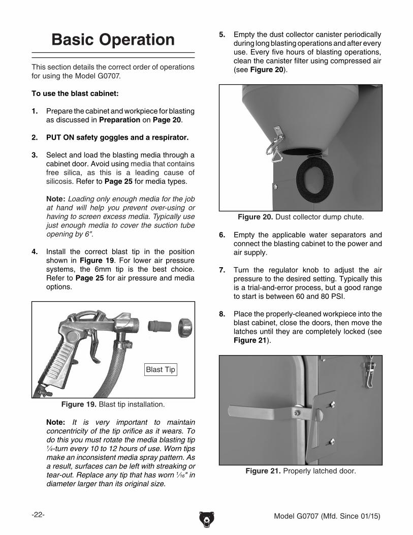
4. Install the correct blast tip in the position shown in Figure 19. For lower air pressure systems, the 6mm tip is the best choice. Refer to Page 25 for air pressure and media options.
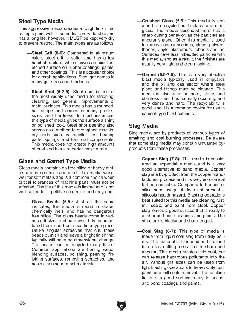
Figure 20. Dust collector dump chute.
5. Empty the dust collector canister periodically during long blasting operations and after every use. Every five hours of blasting operations, clean the canister filter using compressed air (see Figure 20).
6. Empty the applicable water separators and connect the blasting cabinet to the power and air supply.
7. Turn the regulator knob to adjust the air pressure to the desired setting. Typically this is a trial-and-error process, but a good range to start is between 60 and 80 PSI.
8. Place the properly-cleaned workpiece into the blast cabinet, close the doors, then move the latches until they are completely locked (see Figure 21).
Figure 21. Properly latched door.
Figure 19. Blast tip installation.
Note: It is very important to maintain concentricity of the tip orifice as it wears. To do this you must rotate the media blasting tip 1⁄4-turn every 10 to 12 hours of use. Worn tips make an inconsistent media spray pattern. As a result, surfaces can be left with streaking or tear-out. Replace any tip that has worn 1⁄16" in diameter larger than its original size.
Blast Tip

Model G0707 (Mfd. Since 01/15) -23-
9. Inspect the windows (Figure 22) for clarity and for any evidence of damage to the protective film. Peel off worn or damaged film and affix new sheets as required. Replace the sheets BEFORE they are worn through. If using an aggressive media, you may have to double the sheets to protect from wear-through before your blasting project is finished. NEVER WIPE WINDOWS WITH WET OR DRY RAGS! Doing so will scratch the viewing surface. Instead, vacuum media away and then gently brush the remnants off the glass with a soft paint brush. If visibility becomes a problem, refer to Troubleshooting on Page 30 for further solutions.
10. Push the power switch, light, and the dust switches to start the dust collector and to turn the work lamps ON.
11. Point the blast gun tip at the workpiece in a direction where the ricochetting spray of abrasive will not contact the windows.
Figure 22. Viewing windows.
12. Press on the foot pedal for fixed gun blasting, or pull the hand-held blast gun trigger and media will begin spraying from the blast tip. Depending on your blasting gun selection (Figure 23), move the workpiece or blast gun slowly in a methodical circular motion.
Figure 23. Blast gun ON/OFF control.
Note: For most media blasting operations, maintain a blast distance of six inches. Maintain a blasting spray at a 45°-60° angle from the workpiece so the media will ricochet off and not directly impact the lamp or viewing window. Doing this will help maintain workpiece visibility and make the protective viewing window film and media last longer. Do not point the gun or hold the workpiece so the spray pattern is perpendicular or 90°degrees to the surface.
Note: When media blasting thin materials made of aluminum, copper, brass, wood, or other delicate parts, select the correct media and begin blasting at a low pressure, such as 45 PSI. Next, slowly increase the air pressure until you achieve the finish required. When using some types of glass bead media, you may have to keep the operating pressure between 50-80 PSI or the media will break down prematurely. Some media like silicon carbide and aluminium oxide can withstand pressures of up to 120 PSI on this machine; however, most media blasting operations should occur at 80 PSI.
Fixed-Gun
Hand-Held Gun

-24- Model G0707 (Mfd. Since 01/15)
Note: If the gun or metering valve begins to clog or becomes completely clogged during use, cover the hole in the blast tip tightly, then pull the gun trigger or push the foot valve. Air pressure will be then diverted back through the media suction piping and usually blow out the clog.
If clogging still persists, it is likely that the moisture or contamination ratio in the media is too high, or there could be a loose fitting or leak in a hose. Dry out the media, install a moisture trap, screen or replace the media, or check for a leaking hose.
Only use high quality DRY media. DO NOT use regular sand, and recognize when media has broken down and is too fine or loaded up with contaminants to work properly. Worn-out media and contaminants will cause caking and clogging.
If clogging persists, refer to Troubleshooting on Page 30 for further solutions.
Figure 24. Canister plunger.
14. When media blasting is complete, disconnect the cabinet from power and the air supply.
13. Every 20-30 minutes during cabinet use, push the canister plunger in until it stops, then let your thumb slide off of the button so the spring slaps the plunger back against the canister wall. This causes vibration that knocks off the material which is caked onto the outside of the filter (Figure 24). Every five hours of cabinet use, service the dust collector filter. Refer to Maintenance on Page 29 for procedures.

Model G0707 (Mfd. Since 01/15) -25-
Blasting Media
Media Cost vs. ProductivityIt is often assumed that by using low-cost media, such as basic builder's sand or play sand, the worker can enjoy increased productivity costs because sand is so cheap. However, since sand is a "Dull Media," the blasting tip size must be increased and higher air pressure and more CFM are required to increase the blast velocity to over-come the dull media problem. This compensation usually results in longer compressor duty cycles that can overheat some units.
Compressor maintenance cycles, power con-sumption, and water separator service intervals may increase. Additionally, general sand can cause increased down-time from clogging tips, hoses, and valves, and generally create a hazard-ous, silica-laden environment.
With the correct research, excellent productivity can be achieved using sharp media with a smaller tip and less air pressure than with dull media at a higher pressure.
Maximizing Media LifeScreen the used media with a series of wire mesh screens to refine it to one consistent size. When using the blasting cabinet, experiment with using the least amount of media as possible. The result of using less media is that you will have less mate-rial to screen or discard and more fresh media for mixed projects. Store media in a dry place.
Grizzly Blasting Media Part NumbersG6535: 15 lbs. Aluminum Oxide 220 Grit.G6536: 15 lbs. Aluminum Oxide 120 Grit.G6537: 15 lbs. Aluminum Oxide 60 Grit.G6538: 15 lbs. Glass Bead 50-Micron Grit.
Some of the common blasting media types are listed below with the MOH scale hardness value. All media have benefits and drawbacks, such as the quality of surface finish, media life, toxicity, and the precautions that must be taken to prevent environmental damage or personal injury to your respiratory system. However, all media presents a health risk. Never use media that contains free silica.
Aluminum Oxide (8.5-9)For surface finishing, aluminum oxide is one of the most common and widely used media. Having an angular shape, it is considered an extremely sharp, has extended blasting times, and is highly recyclable.
Silicon Carbide (9-9.5)This blast media is considered to be the hardest available. The crystal structure is sharp, cutting is fast and aggressive. This media is often use to engrave and etch glass and stone. Shorter blast-ing periods also result from this hard and sharp media. Silicon carbide has no free silica and it can be recycled many times.
Sand Type Media (6-7)This media is easy to find and gives an average finish that is acceptable for many projects. Sand has a good recycling life and is economical. However, the cutting ability at lower air pressure and CFM can be poor—with a higher hazard of silicosis and machine clogging. Many sand-type media contain free silica and present a health hazard for silicosis.
-26- Model G0707 (Mfd. Since 01/15)
Steel Type MediaThis aggressive media creates a rough finish that accepts paint well. The media is very durable and has a long life; however, it MUST be kept very dry to prevent rusting. The main types are as follows:
—Steel Grit (8-9): Compared to aluminum oxide, steel grit is softer and has a low habit of fracture, which leaves an excellent etched surface on rubber coatings, paints, and other coatings. This is a popular choice for aircraft applications. Steel grit comes in many grit sizes and hardness.
—Steel Shot (6-7.5): Steel shot is one of the most widely used media for stripping, cleaning, and general improvements of metal surfaces. This media has a rounded-ball shape and comes in many grades, sizes, and hardness. In most instances, this type of media gives the surface a shiny or polished look. Steel shot peening also serves as a method to strengthen machin-ery parts such as impeller fins, bearing parts, springs, and torsional components. This media does not create high amounts of dust and has a superior recycle rate.
Glass and Garnet Type MediaGlass media contains no free silica or heavy met-als and is non-toxic and inert. This media works well for soft metals and is a common choice when critical tolerances of machine parts must not be affected. The life of this media is limited and is not well-suited for repetitive screening and recycling.
—Glass Beads (5.5): Just as the name indicates, this media is round in shape, chemically inert, and has no dangerous free silica. The glass beads come in vari-ous grit sizes and hardness. It is manufac-tured from lead-free, soda lime-type glass. Unlike angular abrasives that cut, these beads burnish and leave a bright finish that typically will have no dimensional change. The beads can be recycled many times. Common applications are honing wood, blending surfaces, polishing, peening, fin-ishing surfaces, removing scratches, and basic cleaning of most materials.
—Crushed Glass (5.5): This media is cre-ated from recycled bottle glass, and other glass. The media described here has a sharp cutting behavior, as the particles are angular shaped. Often this media is used to remove epoxy coatings, glues, polyure-thanes, vinyls, elastomers, rubbers and tar. Surfaces have less imbedded particles with this media, and as a result, the finishes are usually very light and clean-looking.
—Garnet (6.5-7.5): This is a very effective blast media typically used in shipyards and the oil and gas sector where steel pipes and fittings must be cleaned. This media is also used on brick, stone, and stainless steel. It is naturally occurring and very dense and hard. The recyclability is good, and it is a common choice for use in cabinet-type blast cabinets.
Slag MediaSlag media are by-products of various types of smelting and coal burning processes. Be aware that some slag media may contain unwanted by-products from these processes.
—Copper Slag (7-8): This media is consid-ered an expendable media and is a very good alternative to sand media. Copper slag is a by-product from the copper manu-facturing process and it is very economical but non-reusable. Compared to the use of silica sand usage, it does not present a silicosis health hazard. Blasting operations best suited for this media are cleaning rust, mill scale, and paint from steel. Copper slag leaves a good surface that is ready to anchor and bond coatings and paints. The structure is blocky and sharp-edged.
—Coal Slag (6-7): This type of media is made from liquid coal slag from utility boil-ers. The material is hardened and crushed into a fast-cutting media that is sharp and angular. This media creates little dust, but can release hazardous pollutants into the air. Various grit sizes can be used from light blasting operations to heavy-duty rust, paint, and mill scale removal. The resulting finish is a good surface ready to anchor and bond coatings and paints.

Model G0707 (Mfd. Since 01/15) -27-
Plastic BeadsPlastic abrasives are available in a variety of types such as urea, melamine, and acrylic com-positions. These beads are shaped just as indi-cated and give reliable and consistent stripping results. Paints, varnishes, rusts, and oxidation can be stripped from soft metals, plastics, and wood. The aerospace and automotive industry are chief consumers of this blast media.
—Urea (3-4): Considered to be an enviorn-mentally-friendly choice, urea is the most commonly used plastic media. It is recy-clable and is an excellent choice for strip-ping tough coatings when speed is a high priority and the surface is not critical.
—Melamine (3-4): Also a long-lasting recy-clable media, this abrasive is the most aggressive in the family of the plastic beads. Due to its hardness, it can strip hard-to-remove coatings and be the sub-stitute for some of the other types of glass beads.
—Acrylic (3-4): This is a multipurpose blast media that is one of the longest lasting types available. It is often used for strip-ping sensitive surfaces or delicate parts that may consist of multiple types of com-pounds. It is available in a wide range of grit sizes.
Soft Blast Media There are many types of "Soft" blast media, many of which are minerals, inert, and organic. Some blast cabinets with dust collection systems require special filters or dust collectors for soft types of media. For the Model G0708, filter cleaning inter-val will have to be increased to maintain flow.
—Ground Walnut: (4.5-5) This is a soft
media that is produced from crushed or ground walnut shells. The structure is multi-faceted and angular with no free silica in the media. Durability is excellent, and this media is a good choice for blast-ing operations where the paint, varnish, or coating must be cleaned but not marred or removed. Hardwoods, jewelry, and elec-trical items can also be cleaned with this media. Using a larger grit under higher pressure settings, paint and varnishes, and engine parts can be cleaned of coke and carbon deposits.
—Pumice (6-7): This media is the softest media available and is a natural volcanic ash that is an inert mineral. Pumice can be used for the most sensitive blasting opera-tions where the painted or finished surface must be entirely unaffected by the removal of the foreign matter. The structure is block-shaped and is honeycombed.
—Ground Corn Cob (4.5): Is an organic, soft blasting grit that has an angular shape. It has excellent surface cleaning behavior that is similar to ground walnut and peanut shells. Corn cob media is commonly used to strip bark off of wood, light coatings, and dirt without surface damage or grain blowout. It is available in a selection of grit sizes.
—Sodium Bicarbonate (2.4): Baking soda is inert and has an excellent ability to remove and absorb the dirt or contaminants from a surface. It will not peen or cut the underly-ing workpiece. This important media can be used where small ports and bores must be cleaned without the hazard of clogging the passages. The workpiece and its pas-sages can be cleaned with water as this blast media is water soluble.

-28- Model G0707 (Mfd. Since 01/15)
SECTION 5: ACCESSORIESACCESSORIES
H7359—Campbell Hausfeld: 5 HP, 60-gallon Air Compressor If you do not need to operate the Model G0707 at full capacity of 25 CFM @ 120 PSI, the H7359 compressor will do an excellent job supplying air for consistent media blasting at 60-80 PSI. 60-gallon tank capacity, 5 HP running, runs on 240V. Compressor: solid cast-iron and twin cylin-der pump, oil lubricated, delivers 18.1/15.4 SCFM at 90/140 psi, 171⁄2 Amps, weighs 381 lbs.
H3719—Porter Cable: 71⁄2 HP, 80-gallon 2-stage Cast-iron Air Compressor
This compressor has a 240V 71⁄2 HP motor, 80-gallon tank, and reaches 175 PSI. The SCFM air delivery is 25 CFM @ 100 PSI/ 23.5 @ 175 PSI. Compressor: has an ASME safety valve, globe valve, tank gauge, and is oil lubricated.
G2815— Campbell Hausfeld: 71⁄2 HP, 80-gallon 2-stage Compressor This compressor has a 240V, 71⁄2 HP motor, and delivers 25.1/27.2 CFM at 175/90 PSI. The tank is a vertical 80-gallon ASME tank. Compressor: includes a a magnetic starter, pressure switch, pressure gauge, oil sight and relief valve, and is oil lubricated. Overall height is 77" tall.
Figure 25. Industrial Compressors.
G2815H3719H7359
Figure 27. Assortment of basic eye protection.
Basic Eye ProtectionT20501—Face Shield Crown Protector 4"T20502—Face Shield Crown Protector 7"T20503—Face Shield WindowT20451—“Kirova” Clear Safety GlassesT20452—“Kirova” Anti-Reflective S. GlassesH7194—Bifocal Safety Glasses 1.5H7195—Bifocal Safety Glasses 2.0H7196—Bifocal Safety Glasses 2.5
T20451
T20452
T20502
T20503
H7194
Figure 26. Half-mask respirator with disposable cartridge filters.
H2499—Small Half-Mask RespiratorH3631—Medium Half-Mask RespiratorH3632—Large Half-Mask RespiratorH3635—Cartridge Filter Pair P100Wood dust has been linked to nasal cancer and severe respiratory illnesses. If you work around-dust everyday, a half-mask respirator can be a lifesaver. Also compatible with safety glasses!

Model G0707 (Mfd. Since 01/15) -29-
SECTION 6: MAINTENANCE
For safe and optimum performance from your machine, follow this maintenance schedule and refer to any specific instructions given in this sec-tion.
Daily Check:• Inspect all fittings and hoses for leaks.• Inspect for damaged or leaking door seals.• Make sure water separators are drained.• Make sure the dust collector is empty and the
filter is clean.• Verify the media is correct for task.• Verify the air pressure is set correctly.• Inspect for worn or damaged power cord.• Look for any other unsafe condition.• Replace window protective film for holes
or excessive etching. Replace the sheets BEFORE they are worn through and the win-dow is damaged.
• Rotate blast tips to compensate for wear.• Blow out dust collector filter every five hours.
Monthly Check:• Use soapy water on fittings and hoses while
looking for bubbles that indicate leaks.• Verify all fasteners and clamps are tight.• Inspect suction lines carefully for spots that
collapse or leak during operation.• Clean/vacuum dust buildup from inside cabi-
net and off motor.• Inspect work gloves for holes or wear.• Empty cabinet, wipe down inside and inspect
for leaks or damage.• Cover windows and repaint bare metal por-
tions of cabinet.• Remove filter and clean/replace as required.
Wipe down the exterior of the cabinet with a light solution of mild dish soap and water, then dry with a clean towel. To avoid scratching windows, never wipe windows with wet or dry rags. Instead, vacuum media away and then gently brush the remnants off of the glass with a soft paint brush.
The blast cabinet is equipped with 6 3⁄4" diameter x 12" long pleated filter that is designed to filter media and contaminants from air that re-enters the shop. During operation, basic de-caking is done manually every 20 to 30 minutes with the canister plunger. Empty the canister (Figure 28) at least every five hours of use. Typically, this media is discarded as it has a high ratio of fine dust contaminants. For major cleaning, unlatch the top of the dust collector and remove the filter element. Inspect all sealing foam and replace as required. Clean the filter canister pleats by carefully blowing it from the inside out with com-pressed air. If usability of the filter is in question, or any holes or tears exist, replace it.
CleaningSchedule
Figure 28. Dust collector service.
Wear safety goggles and a respirator when cleaning the cabinet or the filter. Failure to comply can cause serious personal injury.
Always disconnect power and the air supply to the machine before perform-ing maintenance. Failure to do this may result in serious personal injury.

-30- Model G0707 (Mfd. Since 01/15)
Review the troubleshooting and procedures in this section to fix or adjust your machine if a problem devel-ops. If you need replacement parts or you are unsure of your repair skills, then feel free to call our Technical Support at (570) 546-9663.
SECTION 7: SERVICE
Troubleshooting
Operation
Intermittent, clogging, or no media spray at the blast gun; or striping is occurring on the workpiece.
1. Suction tube has been clogged from a contaminant.
2. Incorrect media.
3. Worn or incorrect blast tip.
4. Low air flow or pressure up to cabinet.
5. Blasting system has incorrect air flow or pressure.
6. Cabinet is overloaded with media.
7. Blast gun is damaged or has bad seals.8. Foot valve is damaged, clogged, or has
leaks.
1. Cover blast tip and press the foot pedal to use air pressure to purge the foot valve and suction system. Repeat this step periodically during blasting operations.
2. Verify that the media chosen is the correct material for your blasting operation, and that the media is not worn out or contaminated with moisture. Screen or replace media as required.
3. Disconnect machine from air and inspect blast tip for wear and rotate 1⁄4 -turn to unworn tip area. Replace or install with correct blast tip.
4. Troubleshoot air supply system and verify the compressor, supply lines, moisture separators, and air dryers have the correct air flow and are in good working order.
5. Adjust the air regulator on cabinet to maintain correct air pressure and flow, and verify no hose kinks or clogs exist.
6. Remove media but leave just enough for blasting operation.
7. Disassemble blast gun, clean and reseal.8. Clean and reseal foot valve.

Model G0707 (Mfd. Since 01/15) -31-
Symptom Possible Cause Possible Solution
Dust collector won't start or circuit breaker trips.
1. Damaged or loose power cord.
2. ON/OFF switch at fault. 3. Circuit breaker/fuse has tripped.
4. Wiring at fault.5. Motor brushes at fault.6. Motor at fault.
1. Re-secure and test the power cord. Replace as required.
2. Test and replace open switch. 3. Verify that a short does not exist and that the motor
brushes are not shorted, replace motor brushes if required, and reset circuit breaker.
4. Repair for open or shorted wiring connections.5. Replace motor brushes.6. Test and replace motor as required.
Lamp is dim or will not illuminate.
1. Lamp is burned out. 2. Ballast is at fault.3. ON/OFF switch at fault. 4. Wiring at fault.
1. Replace both lamp bulbs.2. Replace ballast.3. Test and replace open switch. 4. Repair for open or shorted wiring connections.
Motor and Electrical
Replace the filter when it no longer cleans the air–even after being cleaned with compressed air.
To replace the filter:
1. DISCONNECT MACHINE FROM POWER!
2. Unlatch (Figure 29) the dust collector and lift the entire motor and filter unit out of the canister and place it on a workbench upside down.
3. Spin the wing nut off of the retaining stud, and remove the filter (Figure 29).
4. Place a new five-micron filter over the retain-ing stud, then reinstall the wing nut and the dust collector.
Filter Replacement
Figure 29. Dust collector and filter.
Dust Collector
Latch
Canister
Wing Nut
Wear safety goggles and a respirator when cleaning the cabinet or the filter. Failure to comply can cause serious personal injury.

-32- Model G0707 (Mfd. Since 01/15)
Motor Brush Replacement
4. While pulling the fan cover upwards, use a standard screwdriver to slightly pry out the cover lock tangs (Figure 31) and remove the cover from the motor.
During the life of your media blasting cabinet, you may find it necessary to replace the dust collector motor brushes. If the motor operates loudly, or the dust collector still has low suction after a new filter has been installed, the motor brushes likely have reached the end of their usable life and need to be replaced.
Tools Needed QtyPhillips Screwdriver #2 ..................................... 1Standard Screwdriver #2 .................................. 1Acetone and Cotton Rag ................................... 1Crocus Cloth (From Local Auto Parts Store) ..... 1Brush Set ........................................................... 1
To replace the brushes:
1. DISCONNECT MACHINE FROM POWER!
2. Unlatch the dust collector and lift the entire motor and filter unit out of the canister and place it on a workbench for ease of service (Figure 30).
Figure 30. Motor cover.
Motor Cover
3. Using the Phillips screwdriver, remove the four motor cover screws and the cover (Figure 30).
Latch
Canister
Figure 31. Brush removal.
5. Using the Phillips screwdriver, remove the two retainer screws for each brush housing and remove the retainers (Figure 32).
Retainer
Brush Housing
Figure 32. Retainer removal.
LockTang
Fan Cover

Model G0707 (Mfd. Since 01/15) -33-
6. Lift each brush housing out of its seat and unplug the power wire (Figure 33).
Figure 33. Brush housing removal.
Power Wire
7. Slide the brush assembly apart, clean the housings and brass sleeves with mineral spir-its, and allow the parts to dry (Figure 34).
Figure 34. Brush assembly.
8. Reassemble the housings with the brass sleeves and the new carbon brushes (Figure 34) and set aside.
9. Inspect the commutator surface (Figure 35).
Housing Brass Sleeve
Carbon Brush
—If the brushes have worn deep grooves in the commutator, we recommend replacing the motor. Typically the labor involved with re-turning the commutator on a lathe and then undercutting the insulator segments far exceeds the price of a new motor.
—If the commutator only has minor wear and black-colored carbon tracking (Figure 35), use a fine crocus cloth to polish the com-mutator where the brushes ride. DO NOT use emery cloth or sandpaper to clean the commutator or you will make it out-of-round, which will cause the new brushes to arc, overheat, and wear out quickly.
Finish the cleaning process by using acetone and a cotton rag to wipe off any oils or con-taminants from the commutator.
10. Insert the power wire spade terminal into the brush assembly between the brass sleeve and the housing (Figure 36).
Figure 35. Commutator.
Insert Power Wire Spade Terminal Here.
Figure 36. Brush power lead location.
Carbon Tracking on Commutator Surface

-34- Model G0707 (Mfd. Since 01/15)
Figure 37. Brush retainer installation.
12. Install and tighten the brush housing retaining screws.
13. When the brush housings are installed, make sure to route the brush power wires well away from the commutator, as shown in Figure 38, or the commutator will wear into the wire, causing an electrical short.
Figure 38. Safe power wire routing.
Figure 39. Fan cover installation.
14. Place the fan cover back onto the motor so the lock tangs lock onto the brush housings, as shown in Figure 39.
15. Re-install the motor cover and the dust col-lector assembly into the canister, and latch the dust collector in place.
16. Test the dust collector operation.
11. Place the brush housing into the brush seat on the motor, and place the retainer over the brush housing so the lock lug drops into the slot in the brush housing (Figure 37).
CorrectIncorrect
Lock Tangs

Model G0707 (Mfd. Since 01/15) -35-
These pages are current at the time of printing. However, in the spirit of improvement, we may make chang-es to the electrical systems of future machines. Study this section carefully. If there are differences between your machine and what is shown in this section, call Technical Support at (570) 546-9663 for assistance BEFORE making any changes to the wiring on your machine.
SECTION 8: WIRING
SHOCK HAZARD. Working on wiring that is con-nected to a power source is extremely dangerous. Touching electrified parts will result in personal injury including but not limited to severe burns, electrocution, or death. Disconnect the power from the machine before servicing electrical com-ponents!
MODIFICATIONS. Modifying the wiring beyond what is shown in the diagram may lead to unpre-dictable results, including serious injury or fire. This includes the installation of unapproved after-market parts.
WIRE CONNECTIONS. All connections must be tight to prevent wires from loosening during machine operation. Double-check all wires dis-connected or connected during any wiring task to ensure tight connections.
CIRCUIT REQUIREMENTS. You MUST follow the requirements at the beginning of this manualwhen connecting your machine to a power source.
WIRE/COMPONENT DAMAGE. Damaged wires or components increase the risk of serious per-sonal injury, fire, or machine damage. If you notice that any wires or components are damaged while performing a wiring task, replace those wires or components.
MOTOR WIRING. The motor wiring shown inthese diagrams is current at the time of printingbut may not match your machine. If you find thisto be the case, use the wiring diagram inside the motor junction box.
CAPACITORS/INVERTERS. Some capacitorsand power inverters store an electrical charge for up to 10 minutes after being disconnected from the power source. To reduce the risk of being shocked, wait at least this long before working on capacitors.
EXPERIENCING DIFFICULTIES. If you are expe-riencing difficulties understanding the information included in this section, contact our Technical Support at (570) 546-9663.
Wiring Safety Instructions
The photos and diagrams included in this section are best viewed in color. You can view these pages in color at www.grizzly.com.

-36- Model G0707 (Mfd. Since 01/15)READ ELECTRICAL SAFETY ON PAGE 35!
Control Box Wiring Diagram
Main Wiring Diagram
40W Ballast110V-130V
FL T8 18W
FL T8 18W
110 VACPlug
Worklamp Assembly
HotNeturalHot
In: 110VAC 60Hz Out: 16VAC
Transformer
Ground
Hot
125 PSI Incoming
Air Supply
AirSpool Valve
AirControl
Solenoid
Air RegulatorPSI Gauge
15A Fuse
XH
350
Power
Ligh
t
Ligh
t
Ligh
t
Ligh
t
Ligh
t
Circuit
Door
Closed
Fixed
Gun Mov
eable
Gun
Dust CollectorSwitch
Circuit Board
LampSwitch
Power Switch
CN
7C
N6
CN
5C
N4
CN
3
K3
K2
K1
B
A
CN
2C
N1
K4
K4
CF1CF2
T-IN
T-OUT
Bulb
Bulb
Wire colors shown here were accu-rate at time of printing, but they may vary over time. If wire colors on your unit are different than shown here, it does not necessarily mean the wire connection locations have changed.
ToDust Collector
Male PlugPage 37 To Foot
PedalSwitch
Page 37
To DoorLimit Switches
Page 37
ToHandHeldBlastGunPage
39
ToFixed Blast
Gun Page 39

Model G0707 (Mfd. Since 01/15) -37-READ ELECTRICAL SAFETY ON PAGE 35!
Components Wiring Diagram
Dust Collector
Motor
Ground
View this page in color at www.grizzly.com.
HotHot
OMKQN
A
Door Limit Switches are Solid State. Wire as follows:
Brown: 10-30 VDCBlack: PNP NOBlue: 0V
OMKQN
B
ToBlast Cabinet Female Plug
Page 36
ToCircuit Board
Page 36
ToCircuit Board
Page 36
Figure 45
Foot PedalSwitch
Figure 46
Left Door Limit
SwitchFigure 47
RightDoor Limit
SwitchFigure 47
Wiring Parts Page

-38- Model G0707 (Mfd. Since 01/15)READ ELECTRICAL SAFETY ON PAGE 35!
Figure 41. Control system.
Figure 47. Door limit switch.
Figure 42. Overall electrical system.
Figure 43. Dust collector unit.
Figure 45. Dust collector motor.
Figure 44. Air control system.
Figure 46. Foot switch.
Electrical Component Locations
Figure 40. Lamp ballast.

Model G0707 (Mfd. Since 01/15) -39-READ ELECTRICAL SAFETY ON PAGE 35!
Hand-HeldBlast Gun
Two-Stage Air Compresssor
Fixed GunFoot Valve
Cabinet Hopper with Media
WARNING!DISCONNECT POWER AND AIR SUPPLY BEFORE ADJUSTMENTS, MAINTENANCE, OR SERVICE.
Bla
st C
abin
et
Dedicated Media Blasting Air Dryer System
FixedBlast Gun
Quick DisconnectFitting
Control Panel
Air System DiagramAir System Diagram
ToCircuit Board
Page 36
To Air Spool ValvePage 36

-40- Model G0707 (Mfd. Since 01/15)
SECTION 9: PARTS
68
69
12
71
73
81
26
27
28
15
29,30
56-9
56-10
83
65-12
64
67-266
63
56-2
29
56-5
56-6
56-7
56-8
50
52,9,8
5354
55
22
19,20,21
18
1716
56-3
56-4
56-1
9
12
3,45
6
7
10
11 12
1314
47
48
87
88
38
84
85
35
49
40
42
43
44
45
46
7075
59,60, 61
23
82
48
31
72
56
57,58
51,8
3637
89
89
8,24
93
94
98
80
67-1
67-3
67-4
76
65-365-2
65-1
65-665-7
65-865-9
65-10
65-11
65-565-4
29,30
65
29
29,30
29,30
6667
95
96
30
29
15
15
49
928679
9091
,7986
9091
12
90A

Model G0707 (Mfd. Since 01/15) -41-
Parts ListREF PART # DESCRIPTION REF PART # DESCRIPTION1 P0707001 LED INDICATOR 56-8 P0707056-8 CANISTER2 P0707002 POWER SWITCH 56-9 P0707056-9 CANISTER PLUNGER W/SPRING3 P0707003 FUSE HOUSING 56-10 P0707056-10 CLEANOUT DOOR4 P0707004 FUSE 5 X 20MM 15A T15AL250VP 57 P0707057 NIPPLE FITTING5 P0707005 CONTROL PANEL 58 P0707058 ELBOW FITTING6 P0707006 LAMP COVER 59 P0707059 SOLENOID VALVE7 P0707007 LAMP COVER RETAINER CLIP 60 P0707060 SOLENOID NIPPLE FITTING8 P0707008 HEX NUT M3-.5 61 P0707061 SOLENOID ELBOW FITTING9 P0707009 PHLP HD SCR M3-.5 X 10 63 P0707063 WORK TABLE10 P0707010 FLUORESCENT BULB 18W 64 P0707064 RIGHT DOOR11 P0707011 STRAIN RELIEF 65 P0707065 BLAST GUN ASSEMBLY12 P0707012 LAMP HOUSING 65-1 P0707065-1 MEDIA PORT13 P0707013 LAMP SUPPORT 65-2 P0707065-2 AIR JET14 P0707014 CONTROL BOX COVER 65-3 P0707065-3 NOZZLE NUT15 P0707015 FLAT WASHER 4MM 65-4 P0707065-4 DOWEL PIN16 P0707016 JET FITTING 65-5 P0707065-5 TRIGGER17 P0707017 QUICK DISCONNECT FITTING 3/8" 65-6 P0707065-6 O-RING 6.6 X 3 18 P0707018 BRASS NIPPLE 65-7 P0707065-7 METERING PIN19 P0707019 AIR REGULATOR 65-8 P0707065-8 COMPRESSION SPRING20 P0707020 BRASS NIPPLE 65-9 P0707065-9 O-RING 9.8 X 1.9 P1021 P0707021 BRASS ELBOW 65-10 P0707065-10 PLUG22 P0707022 MOUNTING PLATE 65-11 P0707065-11 PUSH-ON FITTING 3/8" 23 P0707023 AIR PRESSURE GAUGE 65-12 P0707065-12 BLAST GUN BODY24 P0707024 LOCK WASHER 3MM 66 P0707066 AIR HOSE26 P0707026 FOOT PEDAL 67 P0707067 FIXED GUN ASSEMBLY27 P0707027 LEG 67-1 P0707067-1 CONNECTOR FITTING28 P0707028 DUMP CHUTE DOOR 67-2 P0707067-2 MEDIA PORT29 P0707029 CABINET SCREW M6-1 X 12 67-3 P0707067-3 BRASS JET30 P0707030 FLANGE NUT M6-1 67-4 P0707067-4 NOZZLE NUT31 P0707031 LATCH 68 P0707068 FENDER WASHER 6MM35 P0707035 RUBBER GLOVE SET 69 P0707069 DRAW TUBE36 P0707036 GLOVE CLAMP 70 P0707070 LARGE WINDOW COVER FILM (5 PACK)37 P0707037 SUPPORT RING 71 P0707071 AIR HOSE 1/2" ID38 P0707038 GLOVE MOUNTING RING 72 P0707072 HOSE CLAMP 1/2"40 P0707040 LOCK NUT M6-1 73 P0707073 MEDIA HOSE 1/2" ID42 P0707042 BLAST CABINET BODY 75 P0707075 SMALL WINDOW COVER FILM (5 PACK)43 P0707043 VIEWING WINDOW SEAL 76 P0707076 ADHESIVE DOOR SEAL 3/8" x 1" x 79"44 P0707044 WINDOW COVER FILM 23-1/2" x 10" 79 P0707079 PHLP HD SCR M4-.7 X 645 P0707045 VIEWING WINDOW GLASS 80 P0707080 TEFLON TAPE46 P0707046 PLEXIGLASS WINDOW 81 P0707081 LATCH RECEIVER47 P0707047 WINDOW FRAME 82 P0707082 WINDOW COVER FILM 21-1/2" x 4"48 P0707048 PHLP HD SCR M4-.7 X 25 83 P0707083 LEFT DOOR49 P0707049 HEX NUT M4-.7 84 P0707084 RUBBER GROMMET50 P0707050 CIRCUIT BOARD 85 P0707085 BAFFLE PLATE51 P0707051 PHLP HD SCR M3-.5 X 20 86 P0707079 FLAT WASHER 4MM52 P0707052 TRANSFORMER 120VAC/16VAC 87 P0707087 DOOR LEVER53 P0707053 STRAIN RELIEF 88 P0707088 LIMIT SWITCH54 P0707054 LAMP WINDOW GLASS 89 P0707089 CROSS BRACE55 P0707055 LAMP WINDOW SEAL 90 P0707090 BLAST TIP 6MM ID56 P0707056 DUST COLLECTOR ASSEMBLY 90A P0707090A NOZZLE SET 4PC56-1 P0707056-1 MOTOR COVER 91 P0707091 BLAST TIP 5MM ID56-2 P0707056-2 UNIVERSAL MOTOR 110V 92 P0707092 LATCH ASSEMBLY56-3 P0707056-3 PLASTIC/BRASS BRUSH HOLDER 93 P0707093 FEMALE POWER CORD 3-WIRE 14-GA56-4 P0707056-4 CARBON BRUSH SET 94 P0707094 MACHINE POWER CORD 3-WIRE 14-GA56-5 P0707056-5 MAIN HOUSING 95 P0707095 FLAT HD SCR M5-.8 X 1056-6 P0707056-6 MALE POWER CORD 3-WIRE 14-GA 96 P0707096 HEX NUT M5-.856-7 P0707056-7 CARTRIDGE FILTER 5-MICRON 98 P0707098 BALLAST 110V-130V 40-WATT

-42- Model G0707 (Mfd. Since 01/15)
Label Placement & Parts List
Safety labels warn about machine hazards and ways to prevent injury. The owner of this machine MUST maintain the original location and readability of the labels on the machine. If any label is removed or becomes unreadable, REPLACE that label before using the machine again. Contact Grizzly at (800) 523-4777 or www.grizzly.com to order new labels.
100101 102
103
104
105
106 108
109
REF PART # DESCRIPTION REF PART # DESCRIPTION100 P0707100 MACHINE ID LABEL 105 P0707105 MODEL NUMBER LABEL101 PLABEL-12A READ MANUAL LABEL 106 P0707106 AIR PRESSURE HAZARD LABEL102 PLABEL-57 GLASSES/RESPIRATOR LABEL 108 P0707108 FILTER CLEANING LABEL103 P0707103 DISCONNECT AIR/POWER LABEL 109 P0707109 GENERAL WARNING LABEL104 P0708104 DUST WARNING LABEL

CU
T A
LON
G D
OT
TE
D L
INE
Name _____________________________________________________________________________
Street _____________________________________________________________________________
City _______________________ State _________________________ Zip _____________________
Phone # ____________________ Email _________________________________________________
Model # ____________________ Order # _______________________ Serial # __________________
WARRANTY CARD
The following information is given on a voluntary basis. It will be used for marketing purposes to help us develop better products and services. Of course, all information is strictly confidential.
1. How did you learn about us? ____ Advertisement ____ Friend ____ Catalog ____ Card Deck ____ Website ____ Other:
2. Which of the following magazines do you subscribe to?
3. What is your annual household income? ____ $20,000-$29,000 ____ $30,000-$39,000 ____ $40,000-$49,000 ____ $50,000-$59,000 ____ $60,000-$69,000 ____ $70,000+
4. What is your age group? ____ 20-29 ____ 30-39 ____ 40-49 ____ 50-59 ____ 60-69 ____ 70+
5. How long have you been a woodworker/metalworker? ____ 0-2 Years ____ 2-8 Years ____ 8-20 Years ____20+ Years
6. How many of your machines or tools are Grizzly? ____ 0-2 ____ 3-5 ____ 6-9 ____10+
7. Do you think your machine represents a good value? _____Yes _____No
8. Would you recommend Grizzly Industrial to a friend? _____Yes _____No
9. Would you allow us to use your name as a reference for Grizzly customers in your area? Note: We never use names more than 3 times. _____Yes _____No
10. Comments: _____________________________________________________________________
_________________________________________________________________________________
_________________________________________________________________________________
_________________________________________________________________________________
____ Cabinetmaker & FDM____ Family Handyman____ Hand Loader____ Handy____ Home Shop Machinist____ Journal of Light Cont.____ Live Steam____ Model Airplane News____ Old House Journal____ Popular Mechanics
____ Popular Science____ Popular Woodworking____ Precision Shooter____ Projects in Metal____ RC Modeler____ Rifle____ Shop Notes____ Shotgun News____ Today’s Homeowner____ Wood
____ Wooden Boat____ Woodshop News____ Woodsmith____ Woodwork____ Woodworker West____ Woodworker’s Journal____ Other:

TAPE ALONG EDGES--PLEASE DO NOT STAPLE
FOLD ALONG DOTTED LINE
FOLD ALONG DOTTED LINE
GRIZZLY INDUSTRIAL, INC.P.O. BOX 2069BELLINGHAM, WA 98227-2069
PlaceStampHere
Name_______________________________
Street_______________________________
City______________State______Zip______
Send a Grizzly Catalog to a friend:

WARRANTY AND RETURNS
Grizzly Industrial, Inc. warrants every product it sells for a period of 1 year to the original purchaser from the date of purchase. This warranty does not apply to defects due directly or indirectly to misuse, abuse, negligence, accidents, repairs or alterations or lack of maintenance. This is Grizzly’s sole written warranty and any and all warranties that may be implied by law, including any merchantability or fitness, for any par-ticular purpose, are hereby limited to the duration of this written warranty. We do not warrant or represent that the merchandise complies with the provisions of any law or acts unless the manufacturer so warrants. In no event shall Grizzly’s liability under this warranty exceed the purchase price paid for the product and any legal actions brought against Grizzly shall be tried in the State of Washington, County of Whatcom.
We shall in no event be liable for death, injuries to persons or property or for incidental, contingent, special, or consequential damages arising from the use of our products.
To take advantage of this warranty, contact us by mail or phone and give us all the details. We will then issue you a “Return Number,’’ which must be clearly posted on the outside as well as the inside of the carton. We will not accept any item back without this number. Proof of purchase must accompany the merchandise.
The manufacturers reserve the right to change specifications at any time because they constantly strive to achieve better quality equipment. We make every effort to ensure that our products meet high quality and durability standards and we hope you never need to use this warranty.
Please feel free to write or call us if you have any questions about the machine or the manual.
Thank you again for your business and continued support. We hope to serve you again soon.
WARRANTY AND RETURNS


![Welcome [cdn0.vox-cdn.com]](https://img.pdfslide.net/doc/110x75/61760ba9b147146c9c747c8b/welcome-cdn0vox-cdncom.jpg)