Embed Size (px)
Citation preview

MODEL G0833PPOLAR BEAR SERIES®
10" HYBRID TABLE SAWw/RIVING KNIFE
OWNER'S MANUAL(For models manufactured since 06/17)
COPYRIGHT © JUNE, 2017 BY GRIZZLY INDUSTRIAL, INC. REVISED MARCH, 2018 (HE)WARNING: NO PORTION OF THIS MANUAL MAY BE REPRODUCED IN ANY SHAPE
OR FORM WITHOUT THE WRITTEN APPROVAL OF GRIZZLY INDUSTRIAL, INC.#19042BLJHMN PRINTED IN CHINA V1.03.18

This manual provides critical safety instructions on the proper setup, operation, maintenance, and service of this machine/tool. Save this document, refer to it often, and use it to instruct other operators.
Failure to read, understand and follow the instructions in this manual may result in fire or serious personal injury—including amputation, electrocution, or death.
The owner of this machine/tool is solely responsible for its safe use. This responsibility includes but is not limited to proper installation in a safe environment, personnel training and usage authorization, proper inspection and maintenance, manual availability and compre-hension, application of safety devices, cutting/sanding/grinding tool integrity, and the usage of personal protective equipment.
The manufacturer will not be held liable for injury or property damage from negligence, improper training, machine modifications or misuse.
Some dust created by power sanding, sawing, grinding, drilling, and other construction activities contains chemicals known to the State of California to cause cancer, birth defects or other reproductive harm. Some examples of these chemicals are:
• Lead from lead-based paints.• Crystalline silica from bricks, cement and other masonry products.• Arsenic and chromium from chemically-treated lumber.
Your risk from these exposures varies, depending on how often you do this type of work. To reduce your exposure to these chemicals: Work in a well ventilated area, and work with approved safety equip-ment, such as those dust masks that are specially designed to filter out microscopic particles.

Table of ContentsINTRODUCTION ............................................... 2
Contact Info.................................................... 2Manual Accuracy ........................................... 2Identification ................................................... 3Controls & Components ................................. 4Glossary of Terms ......................................... 5G0833P Machine Data Sheet ........................ 6
SECTION 1: SAFETY ....................................... 9Safety Instructions for Machinery .................. 9Additional Safety for Table Saws ................. 11Preventing Kickback .................................... 12Protecting Yourself From Kickback.............. 12
SECTION 2: POWER SUPPLY ...................... 13Converting Voltage to 115V ......................... 15
SECTION 3: SETUP ....................................... 16Needed for Setup ......................................... 16Unpacking .................................................... 16Inventory ...................................................... 17Hardware Recognition Chart ....................... 19Cleanup ........................................................ 20Site Considerations ...................................... 21Assembly ..................................................... 22Dust Collection ............................................. 27Test Run ...................................................... 28
SECTION 4: OPERATIONS ........................... 29Operation Overview ..................................... 29Workpiece Inspection................................... 30Non-Through & Through Cuts ..................... 30Blade Requirements .................................... 31Blade Selection ............................................ 31Blade Installation.......................................... 33Blade Guard Assembly ................................ 34Riving Knife .................................................. 38Ripping ......................................................... 39Crosscutting ................................................. 40Miter Cuts..................................................... 40Blade Tilt/Bevel Cuts ................................... 41Dado Cutting ................................................ 41Rabbet Cutting ............................................. 43Resawing ..................................................... 45
SECTION 5: SHOP MADE SAFETY ACCESSORIES .............................................. 50
Featherboards .............................................. 50Push Sticks .................................................. 53Push Blocks ................................................. 54Narrow-Rip Auxiliary Fence & Push Block .. 55Outfeed & Support Tables ........................... 57Crosscut Sled............................................... 57
SECTION 6: AFTERMARKET ACCESSORIES FROM GRIZZLY ............................................. 58
SECTION 7: MAINTENANCE ......................... 59Schedule ...................................................... 59Cleaning & Protecting .................................. 59Lubrication ................................................... 60
SECTION 8: SERVICE ................................... 61Troubleshooting ........................................... 61Blade Tilt Stops ............................................ 63Miter Slot to Blade Parallelism ..................... 65Spreader or Riving Knife Alignment ............ 67Fence Adjustments ...................................... 69Fence Scale Calibration ............................... 72Table/Dado Insert Adjustment ..................... 72Miter Gauge Adjustments ............................ 73Belt Tension & Replacement ....................... 74
SECTION 9: WIRING ...................................... 75Wiring Safety Instructions ............................ 75Wiring Diagram ............................................ 76Electrical Components ................................. 77
SECTION 10: PARTS ..................................... 78Body ............................................................. 78Trunnion ....................................................... 79Power Switch ............................................... 81Blade Guard ................................................. 82Miter Guage ................................................. 83Fence ........................................................... 84Fence Rails .................................................. 85Labels & Cosmetics ..................................... 86
WARRANTY AND RETURNS ........................ 89

-2- Model G0833P (Mfd. Since 06/17)
INTRODUCTION
We stand behind our machines! If you have ques-tions or need help, contact us with the information below. Before contacting, make sure you get the serial number and manufacture date from the machine ID label. This will help us help you faster.
Grizzly Technical Support1815 W. Battlefield
Springfield, MO 65807Phone: (570) 546-9663
Email: [email protected]
We want your feedback on this manual. What did you like about it? Where could it be improved? Please take a few minutes to give us feedback.
Grizzly Documentation ManagerP.O. Box 2069
Bellingham, WA 98227-2069Email: [email protected]
Contact Info
We are proud to provide a high-quality owner’s manual with your new machine!
We made every effort to be exact with the instruc-tions, specifications, drawings, and photographs in this manual. Sometimes we make mistakes, but our policy of continuous improvement also means that sometimes the machine you receive is slightly different than shown in the manual.
If you find this to be the case, and the difference between the manual and machine leaves you confused or unsure about something, check our website for an updated version. We post current manuals and manual updates for free on our web-site at www.grizzly.com.
Alternatively, you can call our Technical Support for help. Before calling, make sure you write down the Manufacture Date and Serial Number from the machine ID label (see below). This information is required for us to provide proper tech support, and it helps us determine if updated documenta-tion is available for your machine.
Manufacture Date
Serial Number
Manual Accuracy

Model G0833P (Mfd. Since 06/17) -3-
For Your Own Safety Read Instruction Manual Before Operating Saw
a) Wear eye protection.b) Use saw-blade guard and spreader for
every operation for which it can be used, including all through sawing.
c) Keep hands out of the line of saw blade.d) Use a push-stick when required.e) Pay particular attention to instructions
on reducing risk of kickback.f) Do not perform any operation freehand.g) Never reach around or over saw blade.
Identification
Become familiar with the names and locations of the controls and features shown below to better understand the instructions in this manual.
Blade Height Lock
Blade Height Handwheel
Miter Gauge
Blade Tilt Lock
Left Extension
Wing
Blade Tilt Handwheel
4" Dust Port
START/STOP Switch
Right Extension
Wing
Blade Guard
Blade Tilt Scale Fence Lock Handle
Dust Collection Hose
Fence
11⁄2" Dust Port

-4- Model G0833P (Mfd. Since 06/17)
Controls & Components
To reduce your risk of serious injury, read this entire manual BEFORE using machine.
Refer to Figures 1–3 and the following descrip-tions to become familiar with the basic controls of this machine.
A. START/STOP Switch: Starts and stops the motor. The switch can be disabled for safety by inserting the disabling pin or a padlock (not included) through the START button.
B. Handwheel Locks: Lock blade height and angle when tightened (one on each handwheel).
C. Blade Tilt Handwheel: Adjusts angle of blade tilt from 90°–45°.
D. Blade Height Handwheel: Adjusts blade height from 0"–31⁄8".
Figure 2. Blade adjustment handwheels and locks.
Figure 1. Location of START/STOP switch.
E. Fence Lock Handle: Locks fence when pushed down, unlocks fence when pulled up.
F. Fence: Guides workpiece as it moves into blade and determines angle of cut. Fence face can be positioned for standard cutting operations, or placed in lower position for blade guard clearance during narrow ripping operations.
G. Fence Lock Knobs: Secure fence when tightened; allow fence to be repositioned along fence tube when loosened.
Figure 3. Location of fence controls.
F
E
D
C
G
A
B

Model G0833P (Mfd. Since 06/17) -5-
The following is a list of common definitions, terms and phrases used throughout this manual as they relate to this table saw and woodworking in general. Become familiar with these terms for assembling, adjusting or operating this machine. Your safety is VERY important to us at Grizzly!
Arbor: A metal shaft extending from the drive mechanism that is the mounting location for the saw blade.
Bevel Edge Cut: A cut made with the blade tilted to an angle between 0˚ and 45˚ to cut a beveled edge onto a workpiece. Refer to Page 41 for more details.
Blade Guard Assembly: Metal or plastic safety device that mounts over the saw blade. Its func-tion is to prevent the operator from coming into contact with the saw blade. Refer to Page 34 for more details.
Crosscut: Cutting operation in which the cross-cut fence is used to cut across the shortest width of the workpiece. Refer to Page 40 for more details.
Dado Blade: Blade or set of blades that are used to cut grooves and rabbets. Refer to Page 41 for more details. The saw and arbor are not intended to safely use a larger dado blade.
Dado Cut: Cutting operation that uses a dado blade to cut a flat bottomed groove into the face of the workpiece. Refer to Page 41 for more details.
Featherboard: Safety device used to keep the workpiece against the rip fence and against the table surface. Refer to Page 50 for more details.
Kerf: The resulting cut or gap in the workpiece after the saw blade passes through during a cutting operation.
Kickback: An event in which the workpiece is propelled back towards the operator at a high rate of speed.
Non-Through Cut: A cut in which the blade does not cut through the top of the workpiece. Refer to Page 30 for more details.
Parallel: Being an equal distance apart at every point along two given lines or planes (i.e. the rip fence face is parallel to the face of the saw blade).
Perpendicular: Lines or planes that intersect and form right angles (i.e. the blade is perpendicular to the table surface).
Push Stick: Safety device used to push the workpiece through a cutting operation. Used most often when rip cutting thin workpieces. Refer to Page 53 for more details.
Rabbet: Cutting operation that creates an L-shaped channel along the edge of the workpiece. Refer to Page 43 for more details.
Rip Cut: Cutting operation in which the rip fence is used to cut across the widest width of the workpiece. Refer to Page 39 for more details.
Riving Knife: Metal plate located behind the blade. It maintains the kerf opening in the wood when performing a cutting operation. Refer to Page 38 for more details.
Straightedge: A tool used to check the flatness, parallelism, or consistency of a surface(s).
Thin Kerf Blade: A blade with a kerf or thickness that is thinner than a standard blade cannot be used on this saw.
Through Cut: A cut in which the blade cuts com-pletely through the workpiece. Refer to Page 31 for more details.
Glossary of Terms

-6- Model G0833P (Mfd. Since 06/17)
The information contained herein is deemed accurate as of 3/25/2018 and represents our most recent product specifications.Due to our ongoing improvement efforts, this information may not accurately describe items previously purchased. PAGE 1 OF 3Model G0833P
MACHINE DATASHEET
Customer Service #: (570) 546-9663 · To Order Call: (800) 523-4777 · Fax #: (800) 438-5901
MODEL G0833P 10" HYBRID TABLE SAW WITH RIVINGKNIFE, POLAR BEAR SERIES
Product Dimensions:
Weight.............................................................................................................................................................. 396 lbs.Width (side-to-side) x Depth (front-to-back) x Height..................................................................... 62 x 39 x 47-3/4 in.Footprint (Length x Width)............................................................................................................... 20-1/2 x 19-1/2 in.
Shipping Dimensions:
Carton #1Type.................................................................................................................. Cardboard Box on Wood SkidsContent................................................................................................................................................. MachineWeight.................................................................................................................................................... 388 lbs.Length x Width x Height............................................................................................................. 30 x 25 x 42 in.Must Ship Upright......................................................................................................................................... Yes
Carton #2Type........................................................................................................................................... Cardboard BoxContent..................................................................................................................................................... FenceWeight...................................................................................................................................................... 21 lbs.Length x Width x Height............................................................................................................... 37 x 15 x 7 in.Must Ship Upright.......................................................................................................................................... No
Carton #3Type........................................................................................................................................... Cardboard BoxContent....................................................................................................................................................... RailsWeight...................................................................................................................................................... 33 lbs.Length x Width x Height................................................................................................................. 64 x 6 x 4 in.Must Ship Upright.......................................................................................................................................... No
Electrical:
Power Requirement............................................................................................. 115V or 230V, Single-Phase, 60 HzPrewired Voltage.................................................................................................................................................. 230VFull-Load Current Rating....................................................................................................... 16A at 115V, 8A at 230VMinimum Circuit Size.......................................................................................................... 20A at 115V, 15A at 230VConnection Type....................................................................................................................................... Cord & PlugPower Cord Included.............................................................................................................................................. YesPower Cord Length................................................................................................................................................. 6 ft.Power Cord Gauge......................................................................................................................................... 14 AWGPlug Included.......................................................................................................................................................... YesIncluded Plug Type................................................................................................................................. 6-20 for 230VRecommended Plug Type...................................................................................................................... 5-20 for 115VSwitch Type..................................................... START/STOP Push Button w/Large Shut-Off Paddle & Disabling PinVoltage Conversion Kit............................................................................................................................ P0833P224X

Model G0833P (Mfd. Since 06/17) -7-
The information contained herein is deemed accurate as of 3/25/2018 and represents our most recent product specifications.Due to our ongoing improvement efforts, this information may not accurately describe items previously purchased. PAGE 2 OF 3Model G0833P
Motors:Main
Horsepower................................................................................................................................................ 2 HPPhase............................................................................................................................................ Single-PhaseAmps....................................................................................................................................................... 16A/8ASpeed................................................................................................................................................ 3450 RPMType................................................................................................................. TEFC Capacitor-Start InductionPower Transfer ....................................................................................................................... Poly-V Belt DriveBearings..................................................................................................... Shielded & Permanently Lubricated
Main Specifications:
Main Information
Table Saw Type....................................................................................................................................... HybridMaximum Blade Diameter......................................................................................................................... 10 in.Arbor Size................................................................................................................................................. 5/8 in.Arbor Speed...................................................................................................................................... 3850 RPMMaximum Width of Dado...................................................................................................................... 13/16 in.Blade Tilt Direction....................................................................................................................................... LeftMax Blade Tilt......................................................................................................................................... 45 deg.Maximum Depth of Cut At 90 Degrees.................................................................................................. 3-1/8 in.Maximum Depth of Cut At 45 Degrees................................................................................................ 2-3/16 in.Max Rip Right of Blade w/Included Fence & Rails.............................................................................. 31-1/2 in.Max Rip Left of Blade w/Included Fence & Rails................................................................................. 11-3/8 in.
Additional Blade Information
Included Blade Information.................................................................................................................. 10" x 40TRiving Knife/Spreader Thickness.............................................................................................................. 0.1 in.Required Blade Body Thickness.............................................................................................. 0.063 – 0.094 in.Required Blade Kerf Thickness............................................................................................... 0.102 – 0.126 in.Rim Speed at Max Blade Diameter................................................................................................. 10,074 FPM
Table Information
Floor to Table Height........................................................................................................................... 34-1/4 in.Table Size with Extension Wings Width.................................................................................................... 40 in.Table Size with Extension Wings Depth.................................................................................................... 27 in.Distance Front of Table to Center of Blade......................................................................................... 16-1/4 in.Distance Front of Table to Blade At Maximum Cut............................................................................. 11-1/2 in.Main Table Size Thickness.................................................................................................................... 1-1/2 in.
Fence Information
Fence Type.................................................................................... Camlock T-Shape w/High-Low Profile FaceFence Size Length............................................................................................................................... 34-5/8 in.Fence Size Width.................................................................................................................................. 4-5/8 in.Fence Size Height....................................................................................................................................... 3 in.Fence Rail Type............................................................................................... Square Steel Tubing/Angle IronFence Rail Length............................................................................................................................... 61-7/8 in.Fence Rail Width......................................................................................................................................... 2 in.Fence Rail Height.................................................................................................................................. 1-5/8 in.
Miter Gauge Information
Miter Gauge Slot Type.............................................................................................................................. T-SlotMiter Gauge Slot Size Width..................................................................................................................... 3/4 in.Miter Gauge Slot Size Height................................................................................................................... 3/8 in.

-8- Model G0833P (Mfd. Since 06/17)
The information contained herein is deemed accurate as of 3/25/2018 and represents our most recent product specifications.Due to our ongoing improvement efforts, this information may not accurately describe items previously purchased. PAGE 3 OF 3Model G0833P
Construction
Table....................................................................................................................... Precision-Ground Cast IronWings...................................................................................................................... Precision-Ground Cast IronCabinet................................................................................................................................... Pre-Formed SteelTrunnions............................................................................................................................................. Cast IronFence Assembly......................................................................................................... Steel w/Aluminum FenceRails........................................................................................................................................................... SteelMiter Guage Construction.................................................................................................................... Cast IronGuard............................................................................................................................................. Clear PlasticBody/Cabinet Paint Type/Finish................................................................................................ Powder CoatedArbor Bearings.............................................................................................. Sealed & Permanently Lubricated
Other Related Information
Number of Dust Ports....................................................................................................................................... 2Dust Port Size............................................................................................................................ 4 in. & 1-1/2 in.Compatible Mobile Base........................................................................................................................ D2057A
Other Specifications:
Country of Origin ................................................................................................................................................ ChinaWarranty ........................................................................................................................................................... 1 YearApproximate Assembly & Setup Time .............................................................................................................. 1 HourSerial Number Location ................................................................................................................... Machine ID LabelSound Rating ..................................................................................................................................................... 87 dBISO 9001 Factory .................................................................................................................................................. YesCertified by a Nationally Recognized Testing Laboratory (NRTL) .......................................................................... No
Features:
Fully-Enclosed, Quick-Release Blade Guard and SpreaderQuick-Release Riving KnifeZinc Alloy Hinged Motor Cover4" & 1-1/2" Dust PortsHeavy Cast HandwheelsT-Slot Miter GaugePoly-V Serpentine Drive Belt System for Reduced Noise/VibrationPrecision-Ground Cast-Iron TableLarge Cabinet-Mounted, Cast-Iron TrunnionsDurable Powder-Coated FinishDeluxe 2-Position Aluminum Rip FenceEasy-Glide Fence System with Added Micro-Adjustment ControlsStandard & Dado Table InsertsBuilt-In Dust Port on Blade GuardIncluded 10" x 40T Carbide-Tipped Blade

Model G0833P (Mfd. Since 06/17) -9-
ELECTRICAL EQUIPMENT INJURY RISKS. You can be shocked, burned, or killed by touching live electrical components or improperly grounded machinery. To reduce this risk, only allow qualified service personnel to do electrical installation or repair work, and always disconnect power before accessing or exposing electrical equipment.
DISCONNECT POWER FIRST. Always discon-nect machine from power supply BEFORE making adjustments, changing tooling, or servicing machine. This prevents an injury risk from unintended startup or contact with live electrical components.
EYE PROTECTION. Always wear ANSI-approved safety glasses or a face shield when operating or observing machinery to reduce the risk of eye injury or blindness from flying particles. Everyday eyeglasses are NOT approved safety glasses.
OWNER’S MANUAL. Read and understand this owner’s manual BEFORE using machine.
TRAINED OPERATORS ONLY. Untrained oper-ators have a higher risk of being hurt or killed. Only allow trained/supervised people to use this machine. When machine is not being used, dis-connect power, remove switch keys, or lock-out machine to prevent unauthorized use—especially around children. Make your workshop kid proof!
DANGEROUS ENVIRONMENTS. Do not use machinery in areas that are wet, cluttered, or have poor lighting. Operating machinery in these areas greatly increases the risk of accidents and injury.
MENTAL ALERTNESS REQUIRED. Full mental alertness is required for safe operation of machin-ery. Never operate under the influence of drugs or alcohol, when tired, or when distracted.
For Your Own Safety, Read Instruction Manual Before Operating This Machine
The purpose of safety symbols is to attract your attention to possible hazardous conditions. This manual uses a series of symbols and signal words intended to convey the level of impor-tance of the safety messages. The progression of symbols is described below. Remember that safety messages by themselves do not eliminate danger and are not a substitute for proper accident prevention measures. Always use common sense and good judgment.
Indicates a potentially hazardous situation which, if not avoided, MAY result in minor or moderate injury. It may also be used to alert against unsafe practices.
Indicates a potentially hazardous situation which, if not avoided, COULD result in death or serious injury.
Indicates an imminently hazardous situation which, if not avoided, WILL result in death or serious injury.
This symbol is used to alert the user to useful information about proper operation of the machine.NOTICE
Safety Instructions for Machinery
SECTION 1: SAFETY

-10- Model G0833P (Mfd. Since 06/17)
WEARING PROPER APPAREL. Do not wear clothing, apparel or jewelry that can become entangled in moving parts. Always tie back or cover long hair. Wear non-slip footwear to reduce risk of slipping and losing control or accidentally contacting cutting tool or moving parts.
HAZARDOUS DUST. Dust created by machinery operations may cause cancer, birth defects, or long-term respiratory damage. Be aware of dust hazards associated with each workpiece mate-rial. Always wear a NIOSH-approved respirator to reduce your risk.
HEARING PROTECTION. Always wear hear-ing protection when operating or observing loud machinery. Extended exposure to this noise without hearing protection can cause permanent hearing loss.
REMOVE ADJUSTING TOOLS. Tools left on machinery can become dangerous projectiles upon startup. Never leave chuck keys, wrenches, or any other tools on machine. Always verify removal before starting!
USE CORRECT TOOL FOR THE JOB. Only use this tool for its intended purpose—do not force it or an attachment to do a job for which it was not designed. Never make unapproved modifica-tions—modifying tool or using it differently than intended may result in malfunction or mechanical failure that can lead to personal injury or death!
AWKWARD POSITIONS. Keep proper footing and balance at all times when operating machine. Do not overreach! Avoid awkward hand positions that make workpiece control difficult or increase the risk of accidental injury.
CHILDREN & BYSTANDERS. Keep children and bystanders at a safe distance from the work area.Stop using machine if they become a distraction.
GUARDS & COVERS. Guards and covers reduce accidental contact with moving parts or flying debris. Make sure they are properly installed, undamaged, and working correctly BEFORE operating machine.
FORCING MACHINERY. Do not force machine. It will do the job safer and better at the rate for which it was designed.
NEVER STAND ON MACHINE. Serious injury may occur if machine is tipped or if the cutting tool is unintentionally contacted.
STABLE MACHINE. Unexpected movement dur-ing operation greatly increases risk of injury or loss of control. Before starting, verify machine is stable and mobile base (if used) is locked.
USE RECOMMENDED ACCESSORIES. Consult this owner’s manual or the manufacturer for rec-ommended accessories. Using improper acces-sories will increase the risk of serious injury.
UNATTENDED OPERATION. To reduce the risk of accidental injury, turn machine OFF and ensure all moving parts completely stop before walking away. Never leave machine running while unattended.
MAINTAIN WITH CARE. Follow all maintenance instructions and lubrication schedules to keep machine in good working condition. A machine that is improperly maintained could malfunction, leading to serious personal injury or death.
DAMAGED PARTS. Regularly inspect machine for damaged, loose, or mis-adjusted parts—or any condition that could affect safe operation. Immediately repair/replace BEFORE operating machine. For your own safety, DO NOT operate machine with damaged parts!
MAINTAIN POWER CORDS. When disconnect-ing cord-connected machines from power, grab and pull the plug—NOT the cord. Pulling the cord may damage the wires inside. Do not handle cord/plug with wet hands. Avoid cord damage by keeping it away from heated surfaces, high traffic areas, harsh chemicals, and wet/damp locations.
EXPERIENCING DIFFICULTIES. If at any time you experience difficulties performing the intend-ed operation, stop using the machine! Contact our Technical Support at (570) 546-9663.

Model G0833P (Mfd. Since 06/17) -11-
Additional Safety for Table Saws
Serious cuts, amputation, or death can occur from contact with rotating saw blade during operation. Workpieces, broken blades, or flying particles thrown by blade can blind or strike operators or bystanders with deadly force. To reduce the risk of these hazards, operator and bystanders MUST completely heed the hazards and warnings below.
FENCE. To reduce risk of kickback, make sure fence remains properly adjusted and parallel with blade. Always lock fence before using.
CUT-OFF PIECES. To avoid risk of injury due to blade contact, turn saw OFF and allow blade to completely stop before removing cut-off pieces near blade or trapped between blade and table insert. Never use your hands to move cut-off pieces away from blade while saw is running.
BLADE ADJUSTMENTS. Adjusting blade height or tilt during operation increases risk of crash-ing blade and sending metal fragments flying with deadly force at operator or bystanders. Only adjust blade height and tilt when blade is com-pletely stopped and saw is OFF.
CHANGING BLADES. Accidental startup while changing saw blade can result in serious injury. To reduce risk of accidental blade contact, always disconnect power before changing blades.
DAMAGED SAW BLADES. Damaged saw blade teeth can become deadly projectiles. Never use blades that have been dropped or damaged.
DADO AND RABBET OPERATIONS. Dado and rabbeting operations require special attention since they must be performed with blade guard removed, which increases risk of blade contact. DO NOT attempt dado or rabbeting operations without first reading these sections in this manual.
CUTTING CORRECT MATERIAL. Cutting metal, glass, stone, tile, etc., increases risk of operator injury due to kickback or flying particles. Only cut natural and man-made wood products, laminate-covered wood products, and some plastics. Never cut materials not intended for this saw.
HAND & BODY POSITIONING. Keep hands away from saw blade and out of blade path dur-ing operation, so they cannot accidentally slip into blade. Only operate at front of machine and always stand to side of blade path. Never reach behind or over blade.
BLADE GUARD. The blade guard protects oper-ator from rotating saw blade. Make sure blade guard is installed, adjusted correctly, and used for all possible “through cuts.” Promptly repair or replace if damaged. Re-install immediately after operations that require its removal.
RIVING KNIFE. Use riving knife for all “non-through cuts.” Make sure it is aligned and posi-tioned correctly. Promptly repair or replace it if damaged.
KICKBACK. Kickback occurs when saw blade ejects workpiece back toward operator. Know how to reduce risk of kickback, and learn how to protect yourself if it does occur.
FEEDING WORKPIECE. Feeding workpiece incorrectly increases risk of kickback. Always allow blade to reach full speed before cutting, feed workpiece from front of saw, making sure workpiece is flat against table and a fence, miter gauge, or other guide is used to feed workpiece in a straight line. Feed cuts through to completion. Never start saw with workpiece touching blade or pull workpiece from behind blade. Never back workpiece out of cut, move it sideways, or perform a “freehand” operation. Never plunge cut.
PUSH STICKS/PUSH BLOCKS. To reduce risk of accidental blade contact, use push sticks/push blocks whenever possible. In event of an accident, these will often take damage that would have occurred to hands/fingers.
-12- Model G0833P (Mfd. Since 06/17)
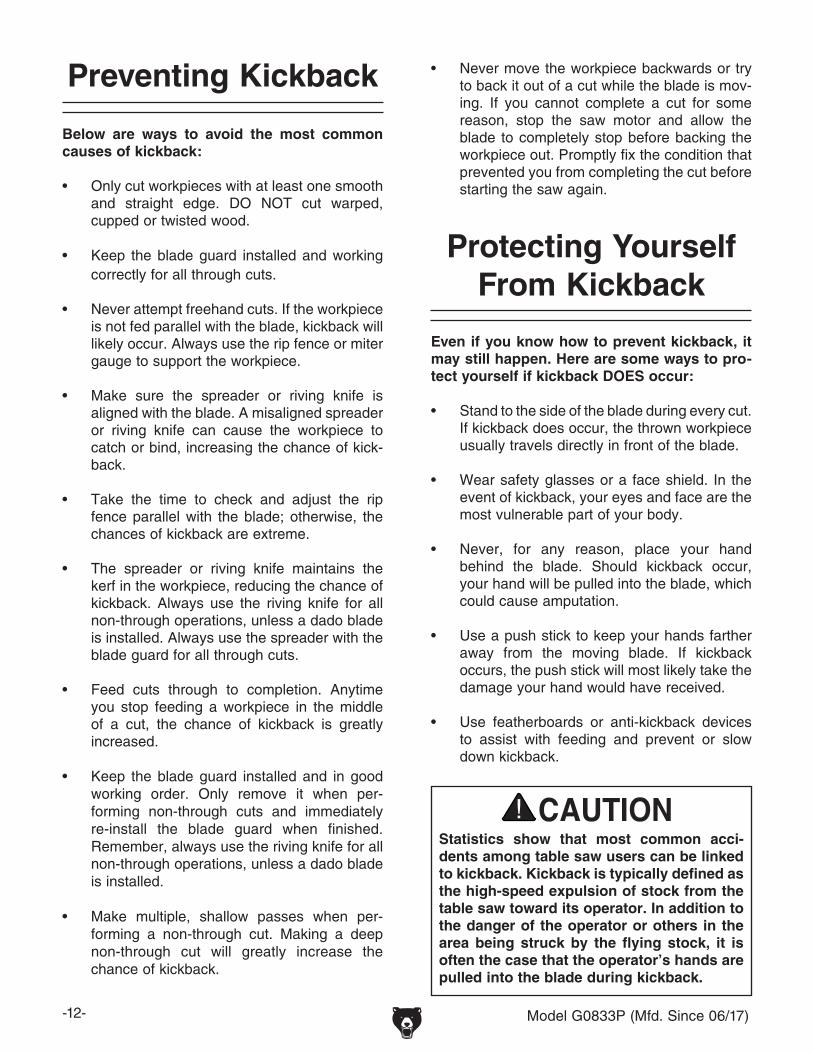
Below are ways to avoid the most common causes of kickback:
• Only cut workpieces with at least one smooth and straight edge. DO NOT cut warped, cupped or twisted wood.
• Keep the blade guard installed and working correctly for all through cuts.
• Never attempt freehand cuts. If the workpiece is not fed parallel with the blade, kickback will likely occur. Always use the rip fence or miter gauge to support the workpiece.
• Make sure the spreader or riving knife is aligned with the blade. A misaligned spreader or riving knife can cause the workpiece to catch or bind, increasing the chance of kick-back.
• Take the time to check and adjust the rip fence parallel with the blade; otherwise, the chances of kickback are extreme.
• The spreader or riving knife maintains the kerf in the workpiece, reducing the chance of kickback. Always use the riving knife for all non-through operations, unless a dado blade is installed. Always use the spreader with the blade guard for all through cuts.
• Feed cuts through to completion. Anytime you stop feeding a workpiece in the middle of a cut, the chance of kickback is greatly increased.
• Keep the blade guard installed and in good working order. Only remove it when per-forming non-through cuts and immediately re-install the blade guard when finished. Remember, always use the riving knife for all non-through operations, unless a dado blade is installed.
• Make multiple, shallow passes when per-forming a non-through cut. Making a deep non-through cut will greatly increase the chance of kickback.
Preventing Kickback
Statistics show that most common acci-dents among table saw users can be linked to kickback. Kickback is typically defined as the high-speed expulsion of stock from the table saw toward its operator. In addition to the danger of the operator or others in the area being struck by the flying stock, it is often the case that the operator’s hands are pulled into the blade during kickback.
Even if you know how to prevent kickback, it may still happen. Here are some ways to pro-tect yourself if kickback DOES occur:
• Stand to the side of the blade during every cut. If kickback does occur, the thrown workpiece usually travels directly in front of the blade.
• Wear safety glasses or a face shield. In the event of kickback, your eyes and face are the most vulnerable part of your body.
• Never, for any reason, place your hand behind the blade. Should kickback occur, your hand will be pulled into the blade, which could cause amputation.
• Use a push stick to keep your hands farther away from the moving blade. If kickback occurs, the push stick will most likely take the damage your hand would have received.
• Use featherboards or anti-kickback devices to assist with feeding and prevent or slow down kickback.
Protecting Yourself From Kickback
• Never move the workpiece backwards or try to back it out of a cut while the blade is mov-ing. If you cannot complete a cut for some reason, stop the saw motor and allow the blade to completely stop before backing the workpiece out. Promptly fix the condition that prevented you from completing the cut before starting the saw again.

Model G0833P (Mfd. Since 06/17) -13-
SECTION 2: POWER SUPPLY
Nominal Voltage .........208V, 220V, 230V, 240VCycle ..........................................................60 HzPhase ........................................... Single-PhaseCircuit Rating ...................................... 15 AmpsPlug/Receptacle ............................. NEMA 6-20
Nominal Voltage .................... 110V, 115V, 120VCycle ..........................................................60 HzPhase ........................................... Single-PhaseCircuit Rating ...................................... 20 AmpsPlug/Receptacle ............................. NEMA 5-20
For your own safety and protection of property, consult an electrician if you are unsure about wiring practices or electrical codes in your area.
Note: Circuit requirements in this manual apply to a dedicated circuit—where only one machine will be running on the circuit at a time. If machine will be connected to a shared circuit where multiple machines may be running at the same time, con-sult an electrician or qualified service personnel to ensure circuit is properly sized for safe operation.
A power supply circuit includes all electrical equipment between the breaker box or fuse panel in the building and the machine. The power sup-ply circuit used for this machine must be sized to safely handle the full-load current drawn from the machine for an extended period of time. (If this machine is connected to a circuit protected by fuses, use a time delay fuse marked D.)
Circuit Information
Circuit Requirements for 230VThis machine is prewired to operate on a power supply circuit that has a verified ground and meets the following requirements:
Circuit Requirements for 115VThis machine can be converted to operate on a power supply circuit that has a verified ground and meets the requirements listed below. (Refer to Voltage Conversion instructions for details.)
AvailabilityBefore installing the machine, consider the avail-ability and proximity of the required power supply circuit. If an existing circuit does not meet the requirements for this machine, a new circuit must be installed. To minimize the risk of electrocution, fire, or equipment damage, installation work and electrical wiring must be done by an electrician or qualified service personnel in accordance with all applicable codes and standards.
Electrocution, fire, shock, or equipment damage may occur if machine is not properly grounded and connected to power supply.
Full-Load Current RatingThe full-load current rating is the amperage a machine draws at 100% of the rated output power. On machines with multiple motors, this is the amperage drawn by the largest motor or sum of all motors and electrical devices that might operate at one time during normal operations.
Full-Load Current Rating at 230V ....... 8 AmpsFull-Load Current Rating at 115V...... 16 Amps
The full-load current is not the maximum amount of amps that the machine will draw. If the machine is overloaded, it will draw additional amps beyond the full-load rating.
If the machine is overloaded for a sufficient length of time, damage, overheating, or fire may result—especially if connected to an undersized circuit. To reduce the risk of these hazards, avoid over-loading the machine during operation and make sure it is connected to a power supply circuit that meets the specified circuit requirements.
-14- Model G0833P (Mfd. Since 06/17)
Grounding RequirementsThis machine MUST be grounded. In the event of certain malfunctions or breakdowns, grounding reduces the risk of electric shock by providing a path of least resistance for electric current.
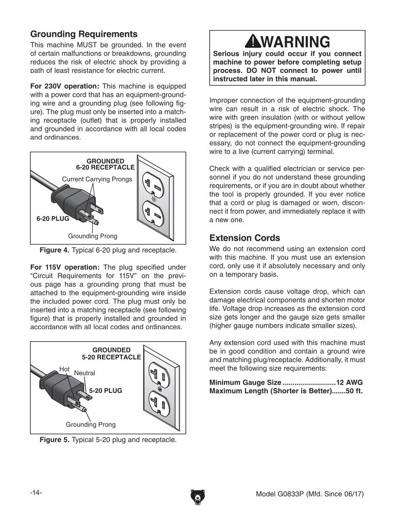
Figure 4. Typical 6-20 plug and receptacle.
Grounding Prong
Current Carrying Prongs
6-20 PLUG
GROUNDED6-20 RECEPTACLE
For 230V operation: This machine is equipped with a power cord that has an equipment-ground-ing wire and a grounding plug (see following fig-ure). The plug must only be inserted into a match-ing receptacle (outlet) that is properly installed and grounded in accordance with all local codes and ordinances.
Figure 5. Typical 5-20 plug and receptacle.
Grounding Prong
HotNeutral
5-20 PLUG
GROUNDED5-20 RECEPTACLE
For 115V operation: The plug specified under “Circuit Requirements for 115V” on the previ-ous page has a grounding prong that must be attached to the equipment-grounding wire inside the included power cord. The plug must only be inserted into a matching receptacle (see following figure) that is properly installed and grounded in accordance with all local codes and ordinances.
Improper connection of the equipment-grounding wire can result in a risk of electric shock. The wire with green insulation (with or without yellow stripes) is the equipment-grounding wire. If repair or replacement of the power cord or plug is nec-essary, do not connect the equipment-grounding wire to a live (current carrying) terminal. Check with a qualified electrician or service per-sonnel if you do not understand these grounding requirements, or if you are in doubt about whether the tool is properly grounded. If you ever notice that a cord or plug is damaged or worn, discon-nect it from power, and immediately replace it with a new one.
Extension CordsWe do not recommend using an extension cord with this machine. If you must use an extension cord, only use it if absolutely necessary and only on a temporary basis.
Extension cords cause voltage drop, which can damage electrical components and shorten motor life. Voltage drop increases as the extension cord size gets longer and the gauge size gets smaller (higher gauge numbers indicate smaller sizes).
Any extension cord used with this machine must be in good condition and contain a ground wire and matching plug/receptacle. Additionally, it must meet the following size requirements:
Minimum Gauge Size ...........................12 AWGMaximum Length (Shorter is Better).......50 ft.
Serious injury could occur if you connect machine to power before completing setup process. DO NOT connect to power until instructed later in this manual.

Model G0833P (Mfd. Since 06/17) -15-
4. Use wire nuts to connect wires as indicated in Figure 7. Twist wire nuts onto their respec-tive wires and wrap them with electrical tape so they will not come loose.
5. Close and secure motor junction box.
6. Remove start/stop switch box from the switch mounting plate.
7. Replace pre-installed 10-amp circuit breaker (see Figure 8) with a 20-amp circuit breaker (part #P0833P224X), then re-install START/STOP switch.
Circuit Breaker
Figure 8. Location of circuit breaker.
8. Install a 5-20 plug on power cord, according to plug manufacturer's instructions.
— If plug manufacturer's instructions are not available, NEMA standard 5-20 plug wiring is provided on Page 76.
Figure 7. Motor rewired to 115V.
Motor Rewired for 115V
GND
Rewired for 110V
The voltage conversion MUST be performed by an electrician or qualified service personnel.
The voltage conversion procedure consists of rewiring the motor and installing the correct plug. A wiring diagram is provided on Page 76 for your reference.
IMPORTANT: If the diagram included on the motor conflicts with the one on Page 76, the motor may have changed since the manual was printed. Use the diagram included on the motor instead.
Items Needed Qty• Phillips Head Screwdriver #2 ..................... 1• Electrical Tape ............................ As Needed• Wire Cutters/Stripper .................................. 1• NEMA 5-20 Plug ......................................... 1• Circuit Breaker 20A (P0833P224X) ............ 1
Converting Voltage to 115V
To convert Model G0833P to 115V:
1. DISCONNECT MACHINE FROM POWER!
2. Cut off existing 6-20 plug.
3. Open motor junction box, then loosen three wire nuts indicated in Figure 6.
Figure 6. Location of wire nuts to be loosened on motor junction box.
110V/220VMOTOR
Motor Prewired for 230V
GND
ConnectWires with Nuts Here
Loosen TheseWire Nuts

-16- Model G0833P (Mfd. Since 06/17)
SECTION 3: SETUP
Needed for Setup
The following are needed to complete the setup process, but are not included with the machine:
Description Qty• Additional Person ....................................... 1• Safety Glasses for Each Person ................ 1• Cleaner/Degreaser (Page 20) .... As Needed• Disposable Shop Rags ............... As Needed• Straightedge 4' ........................................... 1• Wrench or Socket 10mm ............................ 1• Wrench or Socket 13mm ............................ 1• Wrench or Socket 14mm ............................ 1• Phillips Head Screwdriver #2 ..................... 1• Dust Collection System .............................. 1• Dust Hose 4" .............................................. 1• Hose Clamps 4" ......................................... 2
This machine presents serious injury hazards to untrained users. Read through this entire manu-al to become familiar with the controls and opera-tions before starting the machine!
Wear safety glasses during the entire setup process!
This machine and its components are very heavy. Get lifting help or use power lifting equip-ment such as a forklift to move heavy items.
This machine was carefully packaged for safe transport. When unpacking, separate all enclosed items from packaging materials and inspect them for shipping damage. If items are damaged, please call us immediately at (570) 546-9663.
IMPORTANT: Save all packaging materials until you are completely satisfied with the machine and have resolved any issues between Grizzly or the shipping agent. You MUST have the original pack-aging to file a freight claim. It is also extremely helpful if you need to return your machine later.
Unpacking
SUFFOCATION HAZARD!Keep children and pets away from plastic bags or packing materials shipped with this machine. Discard immediately.

Model G0833P (Mfd. Since 06/17) -17-
Box Contents (Figures 9–11) QtyA. Main Table Saw Unit .................................. 1B. Extension Wings ........................................ 2C. Saw Blade 10" x 40T .................................. 1D. Motor Door ................................................. 1E. Arbor Wrench 13/27mm.............................. 1F. Dado Table Insert ....................................... 1G. Blade Guard Dust Port ............................... 1H. Blade Guard Assembly .............................. 1I. Hex Wrench 6-Piece Set 2.5-8mm ............ 1J. Riving Knife ................................................ 1K. Miter Gauge ................................................ 1L. Dust Hose Adapters ................................... 2M. Push Stick .................................................. 1N. Dado Blade Arbor ....................................... 1O. Dust Port .................................................... 1P. Handwheels ................................................ 2Q. Handwheel Lock Knobs ............................. 2R. Handwheel Handles ................................... 2S. Dust Hose 94" x 11⁄2" .................................. 1T. Hose Support ............................................. 1
Figure 10. Extension wings.
NOTICEIf you cannot find an item on this list, care-fully check around/inside the machine and packaging materials. Often, these items get lost in packaging materials while unpack-ing or they are pre-installed at the factory.
Inventory
The following is a list of items shipped with your machine. Before beginning setup, lay these items out and inventory them.
If any non-proprietary parts are missing (e.g. a nut or a washer), we will gladly replace them; or for the sake of expediency, replacements can be obtained at your local hardware store.
Figure 9. Main table saw unit.
A
B
Figure 11. Component inventory.
C DE
F GH
I
JK
L M N
P SQ
TR
O

-18- Model G0833P (Mfd. Since 06/17)
Fasteners (Figure 13) QtyZ. Cap Screws M10-1.5 x 30 (Wing/Table) ............................................... 6AA. Lock Washers 10mm (Wing/Table) ............ 6AB. Flat Washers 10mm (Wing/Table) .............. 6AC. Flat Head Screws M8-1.25 x 35 (Front Rail/Table) ........................................ 4AD. Lock Washers 8mm (Front Rail/Table) ....... 4AE. Flat Washers 8mm (Front Rail/Table) ......... 4AF. Hex Nuts M8-1.25 (Front Rail/Table) .......... 4AG. Cap Screws M6-1 x 16 (Front Rail/Tube) ... 5AH. Lock Washers 6mm (Front Rail/Tube) ........ 5AI. Flat Washers 6mm (Front Rail/Tube) ......... 5AJ. Cap Screws M10-1.5 x 25 (Rear Rail/Table) ........................................ 2AK. Lock Washers 10mm (Rear Rail/Table) ..... 2AL. Flat Washers 10mm (Rear Rail/Table) ....... 2AM. Cap Screws M8-1.25 x 35 (Rear Rail/Wing) ......................................... 2AN. Flat Washers 8mm (Rear Rail/Wing) .......... 4AO. Lock Washers 8mm (Rear Rail/Wing) ........ 2AP. Hex Nuts M8-1.25 (Rear Rail/Wing) ........... 2AQ. Cap Screws M5-.8 x 14 (Switch) ................ 2AR. Lock Washers 5mm (Switch) ...................... 2AS. Flat Washers 5mm (Switch) ....................... 2AT. Wing Nut M6-1 (Dust Hose Support) ......... 1AU. Flat Washer 6mm (Dust Hose Support) ..... 1AV. Hex Nut M6-1 (Dust Hose Support) ........... 1AW. Button Head Cap Screws M6-1 x 12 (Dust Port) .................................................. 4AX. Flat Washers 6mm (Dust Port) ................... 4
Figure 12. Inventory needed to install fence on Model G0833P.
Box Contents Cont'd (Figure 12) QtyU. Front Rail Tube 62" ..................................... 1V. Front Rail Tape Scale ................................. 1W. Front Rail 57" .............................................. 1X. Rear Rail 55" .............................................. 1Y. Fence Assembly ......................................... 1
U
V
W
X
Y
Figure 13. Hardware inventory.
Z
AB
AD
AC
AE
AF
AH
AG
AI
AJ
AK
AL
AM
AN
AO
AP
AT
AU
AQ
AR
AS AV
AW
AX
AA

Model G0833P (Mfd. Since 06/17) -19-
Hardware Recognition Chart
USE THIS CHART TO MATCH UPHARDWARE DURING THE INVENTORYAND ASSEMBLY PROCESS.
5mm
5mm
Flat Head Cap Screw

-20- Model G0833P (Mfd. Since 06/17)
The unpainted surfaces of your machine are coated with a heavy-duty rust preventative that prevents corrosion during shipment and storage. This rust preventative works extremely well, but it will take a little time to clean.
Be patient and do a thorough job cleaning your machine. The time you spend doing this now will give you a better appreciation for the proper care of your machine's unpainted surfaces.
There are many ways to remove this rust preven-tative, but the following steps work well in a wide variety of situations. Always follow the manufac-turer’s instructions with any cleaning product you use and make sure you work in a well-ventilated area to minimize exposure to toxic fumes.
Before cleaning, gather the following:• Disposable rags• Cleaner/degreaser (WD•40 works well)• Safety glasses & disposable gloves• Plastic paint scraper (optional)
Basic steps for removing rust preventative:
1. Put on safety glasses.
2. Coat the rust preventative with a liberal amount of cleaner/degreaser, then let it soak for 5–10 minutes.
3. Wipe off the surfaces. If your cleaner/degreas-er is effective, the rust preventative will wipe off easily. If you have a plastic paint scraper, scrape off as much as you can first, then wipe off the rest with the rag.
4. Repeat Steps 2–3 as necessary until clean, then coat all unpainted surfaces with a quality metal protectant to prevent rust.
Gasoline and petroleum products have low flash points and can explode or cause fire if used to clean machinery. Avoid using these products to clean machinery.
Many cleaning solvents are toxic if inhaled. Only work in a well-ventilated area.
NOTICEAvoid chlorine-based solvents, such as acetone or brake parts cleaner, that may damage painted surfaces.
T23692—Orange Power DegreaserA great product for removing the waxy ship-ping grease from the non-painted parts of the machine during clean up.
Figure 14. T23692 Orange Power Degreaser.
Cleanup

Model G0833P (Mfd. Since 06/17) -21-
Figure 15. Minimum working clearances.
= Power Connection
4" Dust Port
11/2" Dust PortAccessDoor
Swing at 90º
Min. 30"
39"Wal
l
68"
Site Considerations
Weight LoadRefer to the Machine Data Sheet for the weight of your machine. Make sure that the surface upon which the machine is placed will bear the weight of the machine, additional equipment that may be installed on the machine, and the heaviest work-piece that will be used. Additionally, consider the weight of the operator and any dynamic loading that may occur when operating the machine.
Space AllocationConsider the largest size of workpiece that will be processed through this machine and provide enough space around the machine for adequate operator material handling or the installation of auxiliary equipment. With permanent installations, leave enough space around the machine to open or remove doors/covers as required by the main-tenance and service described in this manual. See below for required space allocation.
Physical EnvironmentThe physical environment where the machine is operated is important for safe operation and lon-gevity of machine components. For best results, operate this machine in a dry environment that is free from excessive moisture, hazardous chemi-cals, airborne abrasives, or extreme conditions. Extreme conditions for this type of machinery are generally those where the ambient temperature range exceeds 41°–104°F; the relative humidity range exceeds 20%–95% (non-condensing); or the environment is subject to vibration, shocks, or bumps.
Electrical InstallationPlace this machine near an existing power source. Make sure all power cords are protected from traffic, material handling, moisture, chemicals, or other hazards. Make sure to leave enough space around machine to disconnect power supply or apply a lockout/tagout device, if required.
LightingLighting around the machine must be adequate enough that operations can be performed safely. Shadows, glare, or strobe effects that may distract or impede the operator must be eliminated.
Children or untrained people may be seriously injured by this machine. Only install in an access restricted location.

-22- Model G0833P (Mfd. Since 06/17)
4. Slide groove on back of each handwheel over handwheel shaft pin, as shown in Figure 18.
3. Before closing door, thoroughly clean heavy-duty rust preventative off of gearing inside the saw and coat these with appropriate metal protectant (refer to Lubrication on Page 60 for location of gears).
To assemble table saw:
Figure 17. Motor door installed.
Hinge Socket
2. Remove switch from saw cabinet, and install motor door by inserting door pins into hinge sockets on cabinet (see Figure 17).
Assembly
The machine must be fully assembled before it can be operated. Before beginning the assembly process, refer to Needed for Setup and gather all listed items. To ensure the assembly process goes smoothly, first clean any parts that are cov-ered or coated in heavy-duty rust preventative (if applicable).
1. Using blade height handwheel (refer to Page 3), raise motor and remove foam ship-ping block (see Figure 16). Save block for later machine transport.
Figure 16. Foam shipping block location.
5. Thread a handwheel lock knob into center of each handwheel and tighten, then thread a handle onto each handwheel and tighten (see Figure 19).
Figure 19. Handwheel installed.
Handles
6. Inspect extension wings and main table mat-ing surfaces for burrs or foreign materials that may inhibit assembly.
For a correct fit, mating edges of table and wings must be clean, smooth, and flat. If nec-essary, use a wire brush or file to remove any flashing, dings, or high spots.
Figure 18. Handwheel installed onto shaft pin.
Pin
Groove
Handwheel

Model G0833P (Mfd. Since 06/17) -23-
7. While a helper holds wings in place, attach each extension wing to main table with (3) M10-1.5 x 30 cap screws, 10mm lock wash-ers, and 10mm flat washers removed in Step 5 (see Figure 20).
— If outside end of extension wing tilts up, place strip of masking tape along top edge of main table to shim end of extension wing down (see Figure 22).
Note: After re-installing wings, remove all excess masking tape with a razor blade.
Figure 22. Masking tape location for adjusting the extension wing down.
8. Place straightedge across extension wings and main table to make sure that combined table surface is flat.
— If combined table surface is flat, skip to next step.
— If outside end of extension wing tilts down, place a strip of masking tape along bottom edge of main table to shim end of exten-sion wing up (see Figure 21).
Figure 21. Masking tape location for tilting extension wing up.
Figure 20. Extension wings installed.
x 3
9. Attach front rail to table and extension wings with (4) M8-1.25 x 35 flat head screws, 8mm flat washers, 8mm lock washers, and M8-1.25 hex nuts, as shown in Figure 23. Make sure top of rail is parallel with table top before fully tightening fasteners.
Figure 23. Front rail installed.
Equal
Front Rail
x 4
Main Table
Extension Wing
(1 of 2)

-24- Model G0833P (Mfd. Since 06/17)
14. Install saw blade as outlined in Blade Installation on Page 33.
15. Place fence on rails (on right hand side of blade, as shown in Figure 26).
Note: Make sure cam foot contacts cam on fence lock handle before you place fence on rail; otherwise, fence will not lock onto rail tube.
Figure 26. Fence installed on rails.
Cam Foot
12. Attach rear rail to holes on main table using (2) M10-1.5 x 25 cap screws, 10mm lock washers, and 10mm flat washers, as shown in Figure 25. Check to make sure rear rail is parallel to table and below miter slots before completely tightening cap screws.
13. Secure rear rail to extension wings with (2) M8-1.25 x 35 cap screws, (4) 8mm flat wash-ers, (2) 8mm lock washers, and (2) M8-1.25 hex nuts (see Figure 25).
Figure 25. Rear rail installed.
x 2
x 2
Rear Rail
10. Install front rail tube onto front rail with (5) M6-1 x 16 cap screws, 6mm flat wash-ers, and 6mm lock washers, as shown in Figure 24. Finger-tighten fasteners.
Figure 24. Front rail tube attached to front rail.
11. While standing at front of table, pull rail tube toward you as far as possible, then final tighten fasteners installed in Step 10. This will help make sure there is enough room for fence to slide.
Front Rail Tube
x 5
16. Adjust foot at rear of fence so that gap between fence and table top is even from front to back.
Cam

Model G0833P (Mfd. Since 06/17) -25-
17. Slide fence up against right hand edge of miter slot, and lock it in place. Examine how fence lines up with miter slot.
Note: It is permissible for back of fence to pivot outward not more than 1⁄64" from being parallel with miter slot. This creates a slightly larger opening between fence and blade, at rear of blade, to reduce risk of workpiece binding or burning as it is fed through cut. Many woodworkers intentionally set up their fence in this manner. Keep this in mind before adjusting your fence. For more details, see Figure 119 on Page 71.
Figure 27. Checking fence parallelism with blade.
Fence isParallel to Miter Slot,which is
Parallel toBlade
Miter Slot
Blade
Fence
— If fence is still parallel with miter slot, pro-ceed to Step 18.
— If fence is not parallel with miter slot, then you MUST adjust fence, as described in Fence Adjustments on Page 69, so that it is parallel.
—If miter slot is not parallel with blade, you must follow procedures described in Miter Slot to Blade Parallelism on Page 65.
18. Carefully slide fence so it barely touches saw blade and lock it in place.
19. Lightly mark "0" location on fence tube (under indicator line on pointer window) with a pen-cil, then remove fence.
20. Peel tape, carefully align "0" mark on scale with pencil mark you made on fence tube, and make sure tape is parallel to fence tube along its length.
21. Re-install fence, move it over to just touch blade, and verify that indicator line is directly over "0" mark.
—If you need to correct position of indicator line, loosen button head screws on pointer window, adjust pointer window so line is over "0" mark on tape (see Figure 28), then secure screws.
Figure 28. Aligning rail tape with scale pointer.
22. Install blade guard as outlined on Page 34.
Pointer Window
Indicator Line

-26- Model G0833P (Mfd. Since 06/17)
23. Attach switch to bottom left-hand side of front rail using (2) M5-.8 x 14 cap screws, 5mm lock washers, and 5mm flat washers, as shown in Figure 29.
Figure 29. Switch installed.
x 2
24. Attach dust hose support to rear rail with (1) M6-1 hex nut, 6mm flat washer, and M6-1 wing nut, as shown in Figure 30, so open end of hook faces outward.
Figure 30. Dust hose support installed.
Dust Hose Support
Open End Faces Outward
25. Attach dust port to cabinet using (4) M6-1 x 12 button head cap screws and (4) 6mm flat washers, as shown in Figure 31.
x 4
Figure 31. Dust port installed.

Model G0833P (Mfd. Since 06/17) -27-
4. Fit 4" dust hose over dust port, as shown in Figure 34, and tightly secure it in place with a hose clamp.
Components Needed: QtyDust Hose Adapters 11⁄2" ....................................2Dust Hose 94" x 11⁄2" ..........................................1Dust Hose 4 " (not included) ...............................1Hose Clamps 4" (not included) ..........................2Dust Collection System (not included) ...............1
Dust Collection
Minimum CFM at Dust Port: 500 CFM +Do not confuse this CFM recommendation with the rating of the dust collector. To determine the CFM at the dust port, you must consider these variables: (1) CFM rating of the dust collector, (2) hose type and length between the dust col-lector and the machine, (3) number of branches or wyes, and (4) amount of other open lines throughout the system. Explaining how to cal-culate these variables is beyond the scope of this manual. Consult an expert or purchase a good dust collection "how-to" book.
This machine creates a lot of wood chips/dust during operation. Breathing airborne dust on a regular basis can result in perma-nent respiratory illness. Reduce your risk by wearing a respirator and capturing the dust with a dust collection system.
2. Slide one adapter onto 11⁄2" dust port (see Figure 33), until it fits snugly.
3. Attach dust hose to dust hose support, then insert dust port into rear of blade guard assembly (see Figure 33).
To connect dust collection hoses:
1. Attach a dust hose adapter to each end of dust hose (see Figure 32).
Figure 32. Adapters attached to dust hose.
Adapters
Figure 33. Dust hose attached to saw, hose support, and blade guard dust port.
Hose Support
Figure 34. Dust hoses attached to port.
4" Dust Hose
Hose Clamp
11⁄2" Dust Port
5. Tug hose to make sure it does not come off. Note: A tight fit is necessary for proper perfor-
mance.
Blade Guard
Dust Port
4" Dust Port

-28- Model G0833P (Mfd. Since 06/17)
To test run machine:
1. Lower blade all the way down, and make sure all tools and objects used during setup are cleared away from machine.
2. Connect machine to power source.
3. Turn machine ON, verify motor operation, then turn machine OFF.
The motor should run smoothly and without unusual problems or noises.
5. Press green ON/START button to test dis-abling feature on switch.
— If machine does not start, switch disabling feature is working as designed.
— If machine does start, immediately stop machine. The switch disabling feature is not working correctly. This safety feature must work properly before proceeding with regular operations. Call Tech Support for help.
ON / STARTButton
Pin
OFF / STOPPaddle
Figure 35. Example of switch disabling pin inserted into START button.
4. Insert switch disabling pin through green ON/START button, as shown in Figure 35.Test Run
Once assembly is complete, test run the machine to ensure it is properly connected to power and safety components are functioning correctly.
If you find an unusual problem during the test run, immediately stop the machine, disconnect it from power, and fix the problem BEFORE operating the machine again. The Troubleshooting table in the SERVICE section of this manual can help.
DO NOT start machine until all preceding setup instructions have been performed. Operating an improperly set up machine may result in malfunction or unexpect-ed results that can lead to serious injury, death, or machine/property damage.
Serious injury or death can result from using this machine BEFORE understanding its controls and related safety information. DO NOT operate, or allow others to operate, machine until the information is understood.
The test run consists of verifying the following: 1) The motor powers up and runs correctly, and 2) the safety disabling mechanism on the switch works correctly.

Model G0833P (Mfd. Since 06/17) -29-
SECTION 4: OPERATIONS
To complete a typical operation, the operator does the following:
1. Examines workpiece to make sure it is suit-able for cutting.
2. Adjusts blade tilt, if necessary, to correct angle for desired cut.
3. Adjusts blade height no more than 1⁄4" higher than thickness of workpiece.
4. Adjusts fence to desired width of cut, then locks it in place.
5. Checks outfeed side of machine for proper support and to make sure workpiece can safely pass all the way through blade without interference.
6. Puts on safety glasses, respirator, and hear-ing protection, and locates push sticks/blocks if needed.
7. Starts saw.
8. Feeds workpiece all the way through blade while maintaining firm pressure on workpiece against table and fence, and keeping hands and fingers out of blade path and away from blade.
9. Stops machine immediately after cut is complete.
Operation Overview
The purpose of this overview is to provide the nov-ice machine operator with a basic understanding of how the machine is used during operation, so the machine controls/components discussed later in this manual are easier to understand.
Due to the generic nature of this overview, it is not intended to be an instructional guide. To learn more about specific operations, read this entire manual, seek additional training from experienced machine operators, and do additional research outside of this manual by reading "how-to" books, trade magazines, or websites.
To reduce your risk of serious injury, read this entire manual BEFORE using machine.
If you are not experienced with this type of machine, WE STRONGLY RECOMMEND that you seek additional training outside of this manual. Read books/magazines or get formal training before beginning any proj-ects. Regardless of the content in this sec-tion, Grizzly Industrial will not be held liable for accidents caused by lack of training.
Eye injuries, respiratory problems, or hear-ing loss can occur while operating this tool. Wear personal protective equipment to reduce your risk from these hazards.

-30- Model G0833P (Mfd. Since 06/17)
Non-Through & Through Cuts
Examples of non-through cuts include dadoes and rabbets. Non-through cuts have a higher risk of injury from kickback because the blade guard must be removed. However, the riving knife MUST be installed because it still provides some protection.
IMPORTANT: When making non-through cuts with a dado blade, do not attempt to cut the full depth in one pass. Instead, take multiple light passes to reduce the load on the blade.
A dado blade smaller than 10" will require removal of the riving knife, because the riving knife will be higher than the blade.
Non-Through Cuts
Figure 36. Example of a non-through cut.
A non-through cut is a sawing operation where the blade does not protrude above the top face of the wood stock, as shown in the Figure below.
Workpiece Inspection
Some workpieces are not safe to cut on this machine or may need to be modified before they can be safely cut. Before cutting, inspect all workpieces for the following:
• Material Type: This machine is intended for cutting natural and man-made wood prod-ucts, laminate-covered wood products, and some plastics. Cutting drywall or cementi-tious backer board creates extremely fine dust and may reduce the life of the motor bearings. This machine is NOT designed to cut metal, glass, stone, tile, etc.; cutting these materials with a table saw greatly increases the risk of injury and damage to the saw or blade.
• Foreign Objects: Nails, staples, dirt, rocks and other foreign objects are often embed-ded in wood. While cutting, these objects can become dislodged and hit the operator, cause kickback, or break the blade, which might then fly apart. Always visually inspect your workpiece for these items. If they can’t be removed, DO NOT cut the workpiece.
• Large/Loose Knots: Loose knots can become dislodged during the cutting opera-tion. Large knots can cause kickback and machine damage. Choose workpieces that do not have large/loose knots or plan ahead to avoid cutting through them.
• Wet or “Green” Stock: Cutting wood with a moisture content over 20% causes unneces-sary wear on the blades, increases the risk of kickback, and yields poor results.
• Excessive Warping: Workpieces with exces-sive cupping, bowing, or twisting are danger-ous to cut because they are unstable and may move unpredictably when being cut.
• Minor Warping: Slightly cupped workpieces can be safely supported with cupped side facing the table or fence; however, work-pieces supported on the bowed side will rock during the cut, which could cause kickback.

Model G0833P (Mfd. Since 06/17) -31-
Blade Requirements
When choosing a main blade, make sure the blade size meets the requirements listed below. The thickness of the blade body and teeth can be measured with calipers or any precision measur-ing device.
Blade Size Requirements:• Body Thickness: 0.063"–0.094" (1.8-2.4mm)• Kerf (Tooth) Thickness: 0.102"–0.126" (2.6-3.2mm)• Riving Knife Thickness: 0.1" (2.5mm)• Blade Size Required for Riving Knife: 10"
Figure 38. Ripping blade.
Blade Selection
This section on blade selection is by no means comprehensive. Always follow the saw blade manufacturer's recommendations to ensure safe and efficient operation of your table saw.
Ripping Blade Features:• Best for cutting with the grain• 20-40 teeth• Flat-top ground tooth profile• Large gullets for large chip removal
FlatTopBlade
Through Cuts
Figure 37. Example of a through cut (blade guard not shown for illustrative clarity).
A through cut is a sawing operation in which the workpiece is completely sawn through, as shown in the Figure below. Examples of through cuts are rip cuts, cross cuts, miter cuts, and beveled cuts. The blade guard assembly MUST be used when performing through cuts.
Figure 39. Crosscutting blade.
Crosscut blade features: • Best for cutting across the grain• 60-80 teeth• Alternate top bevel tooth profile• Small hook angle and a shallow gullet
AlternateTopBevel

-32- Model G0833P (Mfd. Since 06/17)
Figure 41. Laminate blade.
Laminate blade features: • Best for cutting plywood or veneer• 40-80 teeth• Triple chip tooth profile• Very shallow gullet
TripleChipBlade
Figure 40. Combination blade.
Combination blade features: • Designed to cut both with and across grain• 40-50 teeth• Alternate top bevel and flat, or alternate top
bevel and raker tooth profile• Teeth are arranged in groups• Gullets are small and shallow (similar to a
cross-cut blade), then large and deep (similar to a ripping blade
AlternateTopBevelandFlat
Thin Kerf Blade: A blade with thinner kerf than a standard blade. Since the spreader/riving knife included with this table saw is sized for standard blades, thin kerf blades cannot be used on this saw unless they meet the Blade Requirements specified in this manual; otherwise, they will increase the risk of kickback.
Figure 42. Stacked dado blade.
Dado BladesStacked Dado Blade (see below): Multiple blades are stacked together to control the cutting width. Stacked dado blades are more expensive than wobble blades, but typically produce higher quality results.
Wobble Dado Blade: A single blade mounted at a slight angle on an arbor hub. The blade angle is adjustable on the hub, and the width of the dado cut is controlled by the angle setting of the blade.

Model G0833P (Mfd. Since 06/17) -33-
Figure 44. Example of removing table saw blade.
Blade Installation
Review this section, even if your saw blade came pre-installed.
To install blade:
1. DISCONNECT MACHINE FROM POWER!
2. Raise arbor all the way up, then remove blade guard and spreader/riving knife (see Pages 34 & 38) and table insert.
3. Push arbor lock (see Figure 43) in and turn blade until it locks in place.
To reduce risk of injury, always disconnect power to saw before changing blades. Since blade is sharp, use extra care and wear gloves when installing it.
4. While pressing arbor lock, use included arbor wrench to loosen and remove arbor nut, flange, and blade (see Figure 44). Arbor nut has right-hand threads; rotate counterclock-wise to loosen.
Figure 43. Location of arbor lock.
Arbor Lock

-34- Model G0833P (Mfd. Since 06/17)
5. Install new blade, flange, and arbor nut on arbor, as shown in Figure 45, with upper teeth facing front of saw. Ensure the tapered edge of the flange faces the arbor nut and the recess faces away from the arbor nut. The arbor nut should be flush with the outer surface of the flange.
IMPORTANT: Make sure you install the com-
ponents in the correct orientation or the saw blade will not be properly secured!
Figure 45. Blade order of installation and teeth facing correct direction.
Arbor Nut
Arbor NutThreads
Flange
RecessTapered Edge
Flange
Flangeand Arbor
Nut
ArborBlade
Front of Table Saw
(Front of Table Saw)
Arbor Nut
Arbor NutThreads
Flange
RecessTapered Edge
Flange
Flangeand Arbor
Nut
ArborBlade
Front of Table Saw
(Front of Table Saw)
Arbor Nut
Arbor NutThreads
Flange
RecessTapered Edge
Flange
Flangeand Arbor
Nut
ArborBlade
Front of Table Saw
(Front of Table Saw)
Flange
Arbor Nut
6. Secure blade with arbor lock, then tighten flange and arbor nut against blade with arbor wrench. DO NOT overtighten.
7. Re-install table insert (see Page 72) and blade guard (see this page) or riving knife (see Page 38).
Blade Guard Assembly
The term "blade guard" refers to the assembly that consists of the clear polycarbonate shield and dust enclosure, the spreader, and the anti-kickback pawls on each side of the spreader (see Figure 46). Each of these components have important safety functions during the operation of the saw.
Figure 46. Blade guard assembly components.
Clear Shield Spreader
Dust Enclosure
Anti-Kickback Pawl
GuardThe clear polycarbonate guard allows the opera-tor to see the blade cut the workpiece during operation. This guard is designed to lift as the workpiece is pushed into the blade and remain in contact with the workpiece throughout the entire cut.
The guard reduces injury risk by providing a bar-rier around the blade that prevents accidental contact and contains flying wood chips.
To ensure that the guard does its job effectively, the guard must always be in the downward posi-tion against the table during idle operation, and the hinge mechanism must be maintained in good working condition so the guard can freely pivot up and down to accommodate the height of the workpiece and return to the table surface.
Surfaces Flush Front of Table Saw

Model G0833P (Mfd. Since 06/17) -35-
SpreaderThe spreader is a metal plate that prevents the newly cut kerf of the workpiece from pinching the backside of the blade, causing kickback.
The spreader also acts as a barrier behind the blade to shield hands from being pulled into the blade if a kickback occurs.
In order to work properly, the spreader cannot be bent or misaligned with the blade. If the spreader gets accidentally bent, take the time to straighten it or just replace it. Using a bent or misaligned spreader will increase the risk of kickback! Refer to Page 67 to check or adjust alignment if necessary.
Installing Blade Guard & Spreader
4. Slide blade guard spreader all the way down into adjustment block, then rotate knurled knob so it disengages bracket and locking pin engages hole in center of spreader.
5. Give spreader an upward tug to verify that it is locked.
Tools Needed QtyHex Wrench 3mm .............................................. 1Straightedge ...................................................... 1
To install blade guard and spreader:
1. DISCONNECT MACHINE FROM POWER!
2. Install table insert, then raise blade all the way up.
3. Slide knurled knob out (see Figure 47) and rotate it so it engages upper bracket.
Figure 47. Knurled knob used to secure spreader.
Locking Pin
Knurled Knob
Upper Bracket
Adjustment Block
The blade guard, when properly installed, should be set up similarly to Figure 48. It should pivot freely up and down and return to the table in the resting position. It should also swing up high enough to accommodate the workpiece.
6. Adjust flat head cap screws (see Figure 48) to make sure table insert is flush with table (use a straightedge as a guide).
Figure 48. Blade guard installed.
Flat Head Cap Screw (1 of 4)

-36- Model G0833P (Mfd. Since 06/17)
— If spreader/riving knife is not inside align-ment zone and not parallel with blade, then it needs to be adjusted. Proceed to "Adjusting Alignment" on Page 68.
Figure 49. Spreader/riving knife alignment zone.
AlignmentZone
Spreader orRiving Knife
Blade Straightedge
7. While lifting up on one side of blade guard and right spreader pawl, place straightedge against blade and spreader, making sure straightedge does not touch a blade tooth.
When properly aligned, spreader/riving knife will be in "Alignment Zone," shown in Figure 49, and will be parallel with blade.
Anti-Kickback PawlsThe anti-kickback pawls allow the workpiece to travel in only one direction. If the workpiece moves backwards, such as during a kickback, the pawls will dig into the workpiece to slow or stop it.
To work properly, the pawls must return to their resting position after pivoting, as shown in Figure 51, and they must NOT be engaged in the arresting hooks.
If the pawls fail to return to the resting position, the pivot area may need to be cleaned or the spring may have been dislodged or broken and will need to be fixed/replaced.
Figure 51. Pawls in resting position.
Pawl
Arresting Hooks
8. Install blade guard dust port and dust collec-tion hose, as shown in Figure 50, and attach hose to dust collection port on table saw body (refer to Page 27).
Figure 50. Dust port and dust collection hose installed on blade guard.
Dust Hose
Dust Port

Model G0833P (Mfd. Since 06/17) -37-
Enabling PawlsTo enable the pawls, lift up on each pawl and move them outward and down until they both touch the table surface, as shown in Figure 51 on Page 36.
When to Use the Blade GuardThe blade guard assembly MUST always be installed on the saw for all normal through cuts (those where the blade cuts all the way through the thickness of the workpiece). If the blade guard is removed for specific operations, always immediately replace it after those operations are complete.
When Not to Use the Blade GuardThe blade guard cannot be used on any non-through cuts (those in which the blade does not cut all the way through the thickness of the workpiece).
IMPORTANT: Whenever the blade guard cannot be used, the riving knife must be installed.
Sometimes the blade guard or its components can get in the way when cutting very narrow workpieces or other specialized cuts. Because the blade guard is provided to decrease your risk of injury, it should not be used if it gets in the way of making a safe cut. Use good judgment!
Disabling PawlsYou might disable the pawls if you are concerned about them scratching a delicate workpiece, or if you believe that they will obstruct a narrow workpiece and cause feeding difficulty or loss of control. Use your best judgment before retracting the pawls, as they are provided for your safety.
Figure 52. Pawls disabled.
To disable pawls:
1. DISCONNECT MACHINE FROM POWER!
2. Rotate one or both arresting hooks down-ward, then place pawls on each of the hooks, as shown in Figure 52.
Arresting Hooks (One Shown)
Pawl
We do not recommend disabling pawls dur-ing normal operations unless absolutely necessary. In most situations, disabling pawls will increase your risk of serious per-sonal injury in event of a kickback.
The pawls are sharp and can lacerate fingers or hands. Use caution, and wear leather gloves when handling the pawls to reduce risk of injury.
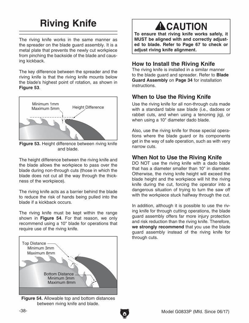
-38- Model G0833P (Mfd. Since 06/17)
Riving Knife
The riving knife works in the same manner as the spreader on the blade guard assembly. It is a metal plate that prevents the newly cut workpiece from pinching the backside of the blade and caus-ing kickback.
Height DifferenceMinimum 1mmMaximum 5mm
The key difference between the spreader and the riving knife is that the riving knife mounts below the blade's highest point of rotation, as shown in Figure 53.
Figure 53. Height difference between riving knife and blade.
The height difference between the riving knife and the blade allows the workpiece to pass over the blade during non-through cuts (those in which the blade does not cut all the way through the thick-ness of the workpiece).
The riving knife acts as a barrier behind the blade to reduce the risk of hands being pulled into the blade if a kickback occurs.
The riving knife must be kept within the range shown in Figure 54. For that reason, we only recommend using a 10" blade for operations that require use of the riving knife.
Minimum 3mmTop Distance
Bottom Distance
Maximum 8mm
Minimum 3mmMaximum 8mm
Figure 54. Allowable top and bottom distances between riving knife and blade.
How to Install the Riving Knife The riving knife is installed in a similar manner to the blade guard and spreader. Refer to Blade Guard Assembly on Page 34 for installation instructions.
To ensure that riving knife works safely, it MUST be aligned with and correctly adjust-ed to blade. Refer to Page 67 to check or adjust riving knife alignment.
When to Use the Riving KnifeUse the riving knife for all non-through cuts made with a standard table saw blade (i.e., dadoes or rabbet cuts, and when using a tenoning jig), or when using a 10" diameter dado blade.
Also, use the riving knife for those special opera-tions where the blade guard or its components get in the way of safe operation, such as with very narrow cuts.
When Not to Use the Riving KnifeDO NOT use the riving knife with a dado blade that has a diameter smaller than 10" in diameter. Otherwise, the riving knife height will exceed the blade height and the workpiece will hit the riving knife during the cut, forcing the operator into a dangerous situation of trying to turn the saw off with the workpiece stuck halfway through the cut.
In addition, although it is possible to use the riv-ing knife for through cutting operations, the blade guard assembly offers far more injury protection and risk reduction than the riving knife. Therefore, we strongly recommend that you use the blade guard assembly instead of the riving knife for through cuts.

Model G0833P (Mfd. Since 06/17) -39-
Figure 56. Typical ripping operation.
6. Set fence to desired width of cut on scale.
7. Adjust blade height so highest saw tooth pro-trudes no more than 1⁄4" above workpiece.
8. Set up safety devices such as featherboards or other anti-kickback devices, making sure no safety devices are contacting blade.
9. Plug saw into power source, turn it ON, and allow it to reach full speed.
Note: Jointed edge of workpiece must slide against fence during cutting operation.
10. Use push stick to feed workpiece through saw blade, as shown in Figure 56, until workpiece is completely beyond saw blade.
To make a rip cut:
1. Review Preventing Kickback on Page 12 and take necessary precautions to reduce likelihood of kickback.
2. If using natural wood, joint one long edge of workpiece on a jointer.
3. DISCONNECT MACHINE FROM POWER!
4. Ensure that blade guard/spreader is installed.
5. Loosen fence knobs (see Figure 55), remove rip fence, then re-install in vertical position for thicker workpieces, or in horizontal position for thinner workpieces and angled cuts where blade is tilted over fence. Lift fence up and tighten each fence knob.
"Ripping" means cutting with the grain of a natural wood workpiece. In man-made materials such as MDF or plywood, ripping means cutting length-wise.
Ripping
Keep blade guard installed and in down position. Failure to do this could result in serious personal injury or death.
Turn saw OFF and allow blade to come to a complete stop before removing cutoff piece. Failure to follow this warning could result in severe lacerations or amputation.
Serious injury can be caused by kickback. Kickback is a high-speed ejection of stock from table saw toward an operator. The operator or bystanders may be struck by fly-ing stock, or operator’s hands can be pulled into blade during kickback.
Vertical
Horizontal
Figure 55. Rip fence positions.
Knob(1 of 3)
Featherboard
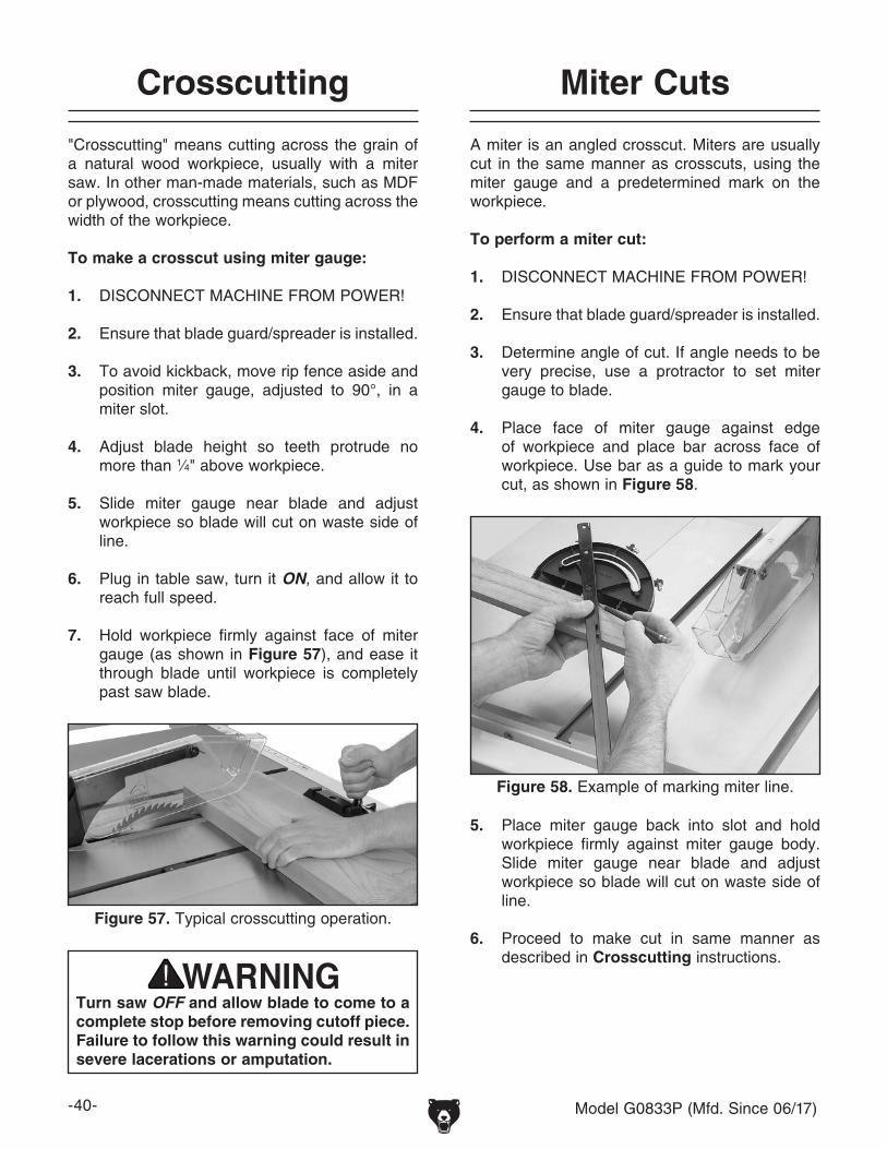
-40- Model G0833P (Mfd. Since 06/17)
"Crosscutting" means cutting across the grain of a natural wood workpiece, usually with a miter saw. In other man-made materials, such as MDF or plywood, crosscutting means cutting across the width of the workpiece.
To make a crosscut using miter gauge:
1. DISCONNECT MACHINE FROM POWER!
2. Ensure that blade guard/spreader is installed.
3. To avoid kickback, move rip fence aside and position miter gauge, adjusted to 90°, in a miter slot.
4. Adjust blade height so teeth protrude no more than 1⁄4" above workpiece.
5. Slide miter gauge near blade and adjust workpiece so blade will cut on waste side of line.
6. Plug in table saw, turn it ON, and allow it to reach full speed.
7. Hold workpiece firmly against face of miter gauge (as shown in Figure 57), and ease it through blade until workpiece is completely past saw blade.
Figure 57. Typical crosscutting operation.
Crosscutting Miter Cuts
A miter is an angled crosscut. Miters are usually cut in the same manner as crosscuts, using the miter gauge and a predetermined mark on the workpiece.
To perform a miter cut:
1. DISCONNECT MACHINE FROM POWER!
2. Ensure that blade guard/spreader is installed.
3. Determine angle of cut. If angle needs to be very precise, use a protractor to set miter gauge to blade.
4. Place face of miter gauge against edge of workpiece and place bar across face of workpiece. Use bar as a guide to mark your cut, as shown in Figure 58.
Figure 58. Example of marking miter line.
5. Place miter gauge back into slot and hold workpiece firmly against miter gauge body. Slide miter gauge near blade and adjust workpiece so blade will cut on waste side of line.
6. Proceed to make cut in same manner as described in Crosscutting instructions.
Turn saw OFF and allow blade to come to a complete stop before removing cutoff piece. Failure to follow this warning could result in severe lacerations or amputation.
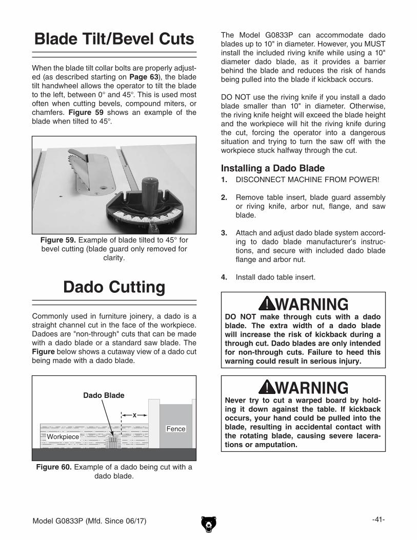
Model G0833P (Mfd. Since 06/17) -41-
Blade Tilt/Bevel Cuts
When the blade tilt collar bolts are properly adjust-ed (as described starting on Page 63), the blade tilt handwheel allows the operator to tilt the blade to the left, between 0° and 45°. This is used most often when cutting bevels, compound miters, or chamfers. Figure 59 shows an example of the blade when tilted to 45°.
Figure 59. Example of blade tilted to 45° for bevel cutting (blade guard only removed for
clarity.
Installing a Dado Blade1. DISCONNECT MACHINE FROM POWER!
2. Remove table insert, blade guard assembly or riving knife, arbor nut, flange, and saw blade.
3. Attach and adjust dado blade system accord-ing to dado blade manufacturer’s instruc-tions, and secure with included dado blade flange and arbor nut.
4. Install dado table insert.
Dado Cutting
Figure 60. Example of a dado being cut with a dado blade.
Commonly used in furniture joinery, a dado is a straight channel cut in the face of the workpiece. Dadoes are "non-through" cuts that can be made with a dado blade or a standard saw blade. The Figure below shows a cutaway view of a dado cut being made with a dado blade.
Dado Blade
WorkpieceFence
The Model G0833P can accommodate dado blades up to 10" in diameter. However, you MUST install the included riving knife while using a 10" diameter dado blade, as it provides a barrier behind the blade and reduces the risk of hands being pulled into the blade if kickback occurs.
DO NOT use the riving knife if you install a dado blade smaller than 10" in diameter. Otherwise, the riving knife height will exceed the blade height and the workpiece will hit the riving knife during the cut, forcing the operator into a dangerous situation and trying to turn the saw off with the workpiece stuck halfway through the cut.
Never try to cut a warped board by hold-ing it down against the table. If kickback occurs, your hand could be pulled into the blade, resulting in accidental contact with the rotating blade, causing severe lacera-tions or amputation.
DO NOT make through cuts with a dado blade. The extra width of a dado blade will increase the risk of kickback during a through cut. Dado blades are only intended for non-through cuts. Failure to heed this warning could result in serious injury.

-42- Model G0833P (Mfd. Since 06/17)
Dado blades have a higher risk of kickback than normal blades because their larger size applies stronger forces to the workpiece. This risk increases relative to the depth and width of the cut. To minimize your risk of serious personal injury, ensure that stock is flat and straight, and make multiple light cuts (rather than one deep cut) to achieve the desired cutting depth.
Figure 61. Example of dado being cut with multiple light cuts, instead of one deep cut.
The Figure below demonstrates the sequential process of making multiple, light cuts that get progressively deeper. The actual number of cuts used should be determined by workpiece hard-ness, total dado depth, and feed rate. In general, if you hear the motor slow down during the cut, you are cutting too deep or feeding too fast.
Dado Blade
WorkpieceFence
Cut 1
WorkpieceFence
Cut 2
WorkpieceFence
Cut 3
FinishedDado Cut
WorkpieceFence
To cut a dado with a dado blade:
1. DISCONNECT MACHINE FROM POWER!
2. Adjust dado blade to desired depth of cut.
3. Adjust distance between fence and inside edge of blade, as shown in Figure 60 on Page 41, to dado length of a workpiece.
— If dadoing across workpiece, use miter gauge and carefully line up desired cut with dado blade. To reduce kickback, DO NOT use fence in combination with miter gauge.
4. Reconnect saw to power source.
5. Turn saw ON. Blade should run smoothly, with no vibrations.
6. When blade has reached full speed, perform test cut with scrap piece of wood.
7. If cut is satisfactory, repeat cut with actual workpiece.
A ripping blade (described on Page 39) is typically the best blade to use when cutting dadoes with a standard blade because it removes sawdust very efficiently.
To use a standard saw blade to cut dadoes:
1. DISCONNECT MACHINE FROM POWER!
2. Mark width of dado cut on workpiece. Include marks on edge of workpiece so cut path can be aligned when workpiece is lying on table.
Cutting Dadoes with a Standard Blade
3. Raise blade up to desired depth of cut (depth of dado channel desired).
4. Set saw up for type of cut you need to make, depending on whether it is a rip cut (Page 39) or crosscut (Page 40).
Cutting Dadoes with a Dado BladeBecause dado blades are much wider than stan-dard blades, they place a greater amount of force against the workpiece when cutting. This addition-al force increases the risk of kickback, requiring the operator to take additional steps when cutting to keep their injury risk at an acceptable level.
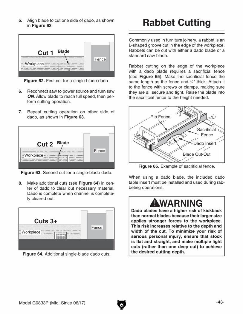
Model G0833P (Mfd. Since 06/17) -43-
Commonly used in furniture joinery, a rabbet is an L-shaped groove cut in the edge of the workpiece. Rabbets can be cut with either a dado blade or a standard saw blade.
Rabbet cutting on the edge of the workpiece with a dado blade requires a sacrificial fence (see Figure 65). Make the sacrificial fence the same length as the fence and 3⁄4" thick. Attach it to the fence with screws or clamps, making sure they are all secure and tight. Raise the blade into the sacrificial fence to the height needed.
Rip Fence
Sacrificial Fence
Dado Insert
Blade Cut-Out
Figure 65. Example of sacrificial fence.
Rabbet Cutting
6. Reconnect saw to power source and turn saw ON. Allow blade to reach full speed, then per-form cutting operation.
7. Repeat cutting operation on other side of dado, as shown in Figure 63.
8. Make additional cuts (see Figure 64) in cen-ter of dado to clear out necessary material. Dado is complete when channel is complete-ly cleared out.
WorkpieceFence
Cut 2 Blade
Figure 63. Second cut for a single-blade dado.
WorkpieceFence
Cuts 3+
Figure 64. Additional single-blade dado cuts.
Blade
WorkpieceFence
Cut 1
Figure 62. First cut for a single-blade dado.
5. Align blade to cut one side of dado, as shown in Figure 62.
Dado blades have a higher risk of kickback than normal blades because their larger size applies stronger forces to the workpiece. This risk increases relative to the depth and width of the cut. To minimize your risk of serious personal injury, ensure that stock is flat and straight, and make multiple light cuts (rather than one deep cut) to achieve the desired cutting depth.
When using a dado blade, the included dado table insert must be installed and used during rab-beting operations.

-44- Model G0833P (Mfd. Since 06/17)
Cutting Rabbets with a Dado Blade
Always use push sticks, featherboards, push paddles and other safety accessories whenever possible to increase safety and control during operations which require that blade guard be removed from saw. ALWAYS replace blade guard after dadoing is complete.
Fence
Dado Blade
Sacrificial Fence
Workpiece
Figure 66. Rabbet cutting.
4. Reconnect saw to power source and turn saw ON. When blade has reached full speed, per-form a test cut with a scrap piece of wood.
— If cut is satisfactory, repeat cut with workpiece.
3. Adjust fence and align workpiece to perform cutting operation, as shown in Figure 66.
1. DISCONNECT MACHINE FROM POWER!
2. Adjust dado blade to height needed for rab-beting operation. When cutting deep rabbets, take more than one pass to reduce risk of kickback.
Cutting Rabbets with a Standard BladeA ripping blade is typically the best blade to use for cutting rabbets when using a standard blade because it removes sawdust very efficiently. (See Page 31 for blade details.) Also, a sacrificial fence is not required when cutting rabbets with a stan-dard blade.
To cut rabbets with a standard blade:
1. DISCONNECT MACHINE FROM POWER!
2. Ensure that riving knife and standard table insert are installed.
3. Mark width of rabbet cut on edge of workpiece, so you can clearly identify intended cut while it is laying flat on saw table.
4. Raise blade up to desired depth of cut (depth of rabbet channel desired).
5. Stand workpiece on edge, as shown in Figure 67, then adjust fence so blade is aligned with inside of your rabbet channel.
FenceBlade
Workpiece
Figure 67. Example of rabbet cutting with a standard blade.
— If workpiece is very tall, or is unstable when placed against fence, lay it flat on table and use a dado blade to perform rabbet cut.

Model G0833P (Mfd. Since 06/17) -45-
WorkpieceFence
Blade
Figure 68. Example of second cut to create a rabbet.
6. Reconnect saw to power source, then per-form cut.
7. Lay workpiece flat on table, as shown in Figure 68, adjust saw blade height to inter-sect with first cut, then perform second cut to complete rabbet.
DO NOT place a tall board on edge to per-form a rabbet cut with a standard blade. Workpieces that are too tall to properly sup-port with fence can easily shift during oper-ation and cause kickback. Instead, place stock flat on saw and perform rabbet cut with a dado blade, as instructed on Page 43.
15 30
45
Resawing
Resawing is the process of cutting a thick piece of stock into one or more thinner pieces. Although resawing can be done with a table saw, we strongly recommend that you use a bandsaw instead.
A bandsaw is the ideal machine for resawing, and resawing with one is fairly easy and safe. A table saw is not intended for resawing, and resawing with one is difficult and dangerous due to the increased risk of kickback from binding and deep cuts, and the increased risk of injury from having to remove the guard.
If you insist on resawing with a table saw, DO NOT do so without using a resaw barrier and wearing a full face shield. The following instructions describe how to build a resaw barrier and add an auxiliary fence to your standard fence, to reduce the risk injury from resawing on a table saw.
Note: To determine the maximum resawing height for this table saw, find the maximum blade height, then double it and subtract 1⁄8".
Resawing operations require proper pro-cedures to avoid serious injury. Extra care must be taken to prevent kickback when resawing. Any tilting or movement of the workpiece away from the fence will cause kickback. Be certain that stock is flat and straight. Failure to follow these warnings could result in serious personal injury.

-46- Model G0833P (Mfd. Since 06/17)
Making Auxiliary FenceAn auxiliary fence is necessary if you are resawing a workpiece that is taller than it is wide. The fence should be no less than 1⁄2" shorter than the board to be resawn.
The fence should be similar to the one in Figure 70 when installed.
Figure 70. Example of auxiliary fence attached to Model G0833P fence face.
Fence
Auxiliary Fence
M6-1 FlatHead Cap Screw
Assembled Auxiliary Fence
Tools Needed: QtyClamps ...............................................................2Drill ....................................................................1Drill Bit 7⁄32" ........................................................1Countersink Drill Bit ............................................1Hex Wrench 5mm ...............................................1Ruler ...................................................................1
#8 x 2"Wood Screw
AssembledResaw Barrier
3⁄4"
3⁄4"
Figure 69. Resaw barrier.
Making Resaw BarrierWhen resawing, the resaw barrier acts in tandem with the rip fence to provide tall support for the workpiece. This minimizes the probability of it binding against the blade and causing kickback.
Tools Needed: QtyTable Saw ..........................................................1Jointer and Planer ....................... RecommendedClamps ............................................... 2 MinimumDrill ....................................................................1Drill Bits 1⁄8", 9⁄64" ....................................... 1 EachCountersink Bit ...................................................1
Components Needed for Resaw Barrier:Wood* 3⁄4" x 51⁄2" x Length of Fence ...................1Wood* 3⁄4" x 3" x Length of Fence ......................1Wood Screws #8 x 2" ........................................4Wood Glue .........................................As Needed
*Only use furniture-grade plywood, kiln-dried hardwood, or HDPE plastic to prevent warping.
To build a resaw barrier:
1. Cut your wood pieces to size specified above. If you are using hardwood, cut pieces over-size, then joint and plane them to correct size to make sure they are square and flat.
2. Pre-drill and countersink four holes approxi-mately 3⁄8" from bottom of 51⁄2" tall wood piece.
3. Glue end of 3" board, clamp boards at a 90° angle with larger board in vertical position, as shown in Figure 69, then fasten together with wood screws.

Model G0833P (Mfd. Since 06/17) -47-
Components Needed:Flat Head Cap Screws M6-1 x (Auxiliary Fence
Width + Fence Tube Width) ........................3Wood* 3⁄4" x 4" x Length of Fence ......................1
*Only use furniture-grade plywood, kiln-dried hardwood, or HDPE plastic to prevent warping.
Fence
Auxiliary Fence
M6-1 FlatHead Cap Screw
Assembled Auxiliary FenceFigure 72. Example auxiliary fence attached to
included fence.
3. Place auxiliary fence board against fence tube. Place a thin metal shim (such as a ruler) between table and bottom of auxiliary fence board to ensure adequate clearance between fence board and table. Clamp in position.
4. Mark location of three mounting holes on auxiliary fence and remove auxiliary fence board from fence tube.
5. Using 7⁄32" drill bit, drill mounting holes in auxiliary fence board. Countersink holes 1⁄16" deep so head of flat head cap screws sits slightly beneath face of auxiliary fence board.
6. Insert (3) flat head cap screws through holes in auxiliary fence board (see Figure 70) and secure with knobs and flat washers removed earlier. The end result should be similar to Figure 72.
To build an auxiliary fence:
1. Cut auxiliary fence board to size. If you are using hardwood, cut board oversize, then joint and plane board to correct size to make sure board is square and flat.
2. Unthread (3) knobs and (3) flat washers securing fence face to fence tube shown in Figure 71, then remove fence.
Figure 71. Location of knobs and flat washers securing fence to fence tube.
Flat Washer Knob(1 of 3

-48- Model G0833P (Mfd. Since 06/17)
Resawing OperationsThe table saw motor is pushed to its limits when resawing. If the motor starts to bog down, slow down your feed rate. Motor overloading and blade wear can be reduced by using a ripping blade. Ripping blades are designed to clear the sawdust quickly.
Components Needed for Resawing:Zero-Clearance Insert ........................................1Ripping Blade 10" ...............................................1Clamps ...............................................................2Shop-Made Auxiliary Fence ...............................1Shop-Made Resaw Barrier .................................1
To perform resawing operations:
1. DISCONNECT MACHINE FROM POWER!
2. Remove standard table insert and blade guard assembly.
3. Install a ripping blade, install riving knife, lower blade below table surface, then install zero-clearance table insert.
You may experience kickback during this procedure. Stand to the side of the blade and wear safety glasses and a full face shield to prevent injury when resawing.
4. Attach auxiliary fence and set it to desired width.
Note: When determining correct width, don't forget to account for blade kerf and inaccuracy of fence scale while auxiliary fence is installed.
5. Place workpiece against auxiliary fence and slide resaw barrier against workpiece, as shown in Figure 73. Now clamp resaw bar-rier to top of table saw at both ends.
AuxiliaryFence
FenceResawBarrier
1/8" Connection
Workpiece
Figure 74. Ideal completed resaw cut.
6. Lower blade completely below table-top, and slide workpiece over blade to make sure it moves smoothly and fits between resaw bar-rier and fence.
7. Raise blade approximately 1 inch, or close to half the height of workpiece (see Figure 74), whichever is less.
Figure 73. Ideal resaw workpiece setup.
AuxiliaryFence
FenceResawBarrier
Workpiece (Front View)

Model G0833P (Mfd. Since 06/17) -49-
11. Turn OFF table saw, then separate parts of workpiece and hand plane remaining ridge to remove it.
12. When finished resawing, remove resaw bar-rier and auxiliary fence, then re-install blade guard/spreader or riving knife and standard table insert.
9. Flip workpiece end-for-end, keeping same side against fence, and run workpiece through blade.
10. Repeat Steps 7–9 until blade is close to half the height of board to be resawn. The ideal completed resaw cut will leave a 1⁄8" connec-tion when resawing is complete as shown in Figure 74 on Page 48. Leaving a 1⁄8" connec-tion will reduce risk of kickback.
8. Plug in table saw, turn it ON, and use a push stick or push block to feed workpiece through blade, using a slow and steady feed rate.
Note: We recommend making a series of light cuts that get progressively deeper, to reduce the chance of stalling the motor.
The danger of kickback increases relative to the depth of a cut. Reduce the risk of kick-back by making multiple passes to achieve the desired depth of cut. Failure to follow these warnings could result in serious per-sonal injury.
Always use push sticks or push paddles to increase safety and control during opera-tions which require that the blade guard and spreader must be removed from the saw. ALWAYS replace blade guard after resawing is complete.

-50- Model G0833P (Mfd. Since 06/17)
SECTION 5: SHOP MADE SAFETY ACCESSORIES
Easily made from scrap stock, featherboards provide an added degree of protection against kickback, especially when used together with push sticks. They also maintain pressure on the workpiece to keep it against the fence or table while cutting, which makes the operation easier and safer because the cut can be completed with-out the operator’s hands getting near the blade. The angled ends and flexibility of the fingers allow the workpiece to move in only one direction.
Making a FeatherboardThis sub-section covers the two basic types of featherboards: 1) Those secured by clamps, or 2) those secured with the miter slot.
Material Needed for FeatherboardHardwood 3⁄4" x 3" x 10" (Minimum) Hardwood 3⁄4" x 6" x 28" (Maximum) ..................1
Additional Material Needed for Mounting Featherboard in Miter SlotHardwood 3⁄8" x (Miter Slot Width) x 5"L ...........1 Wing Nut 1/4"-20 ..................................................1Flat Head Screw 1⁄4"-20 x 2" ...............................1Flat Washer 1⁄4"-20..............................................1
To make a featherboard:
1. Cut a hardwood board approximately 3⁄4" thick to size. The length and width of the board can vary according to your design. Most featherboards are 10"–28" long and 3"–6" wide. Make sure the wood grain runs paral-lel with the length of the featherboard, so the fingers you will create in Step 3 will bend without breaking.
Featherboards
2. Cut a 30º angle at one end of the board.
A
B
30°
2"-3"
1⁄16"-1⁄8"Kerf
1⁄16"-1⁄8"Kerf2"-3"
10" (Minimum)
Initial Cut
Progressively Longer Cuts
3⁄8"
3⁄8"
Figure 75. Patterns for featherboards (top view shown).
3. Make a series of end cuts with the grain 3⁄8"–1⁄4" apart and 2"–3" long, as shown in Figure 75 (A). Alternatively, start cuts at 2"-3" deep, then make them progressively deeper, as shown in Figure 75 (B).
IMPORTANT: Cuts made across the grain result in weak fingers that easily break when flexed. When made correctly, the fingers should with-stand flexing from moderate pressure. To test the finger flexibility, push firmly on the ends with your thumb. If the fingers do not flex, they are likely too thick (the cuts are too far apart).
We recommend using a bandsaw for mak-ing fingers in the next step because it tends to be safer. A table saw can be used, but it will over-cut the underside of the ends, pro-duce a thicker kerf, and require you to stop the blade half-way through the cut, which can be dangerous.
Only Steps 1–3 are required to make a clamp-mounted featherboard. Refer to Page 52 for instructions on clamping.

Model G0833P (Mfd. Since 06/17) -51-
5"
5"
4" Slot
(Top View) (Side View)
3/8"
Countersink on Bottom
1/4" Hole
Figure 77. Miter bar pattern.
5. Cut a miter bar approximately 5" long that will fit in table miter slot, as shown in Figure 77.
7. Mark a 4" line through center of countersunk hole in center, then use a jig saw with a nar-row blade to cut it out.
8. Assemble miter bar and featherboard with a 1⁄4"-20 x flat head screw, flat washer, and a wing nut or a star knob (see Figure 78). Congratulations! Your featherboard is com-plete.
4. Rout a 1⁄4"–3⁄8" wide slot 4"–5" long in workpiece and 1"–2" from short end of feath-erboard (see Figure 76).
Figure 76. Slot routed in featherboard.
1"-2"
4"-5"
1/4"-3/8" Slot
(Side View)Wing Nut
Miter Bar
Featherboard
Flat Head Screw
Flat Washer
Figure 78. Assembling miter slot featherboard components.
Note: The routed slot, countersink hole, and flat head screw are essential for miter bar to clamp into miter slot. When wing nut is tight-ened, it will draw flat head screw upward into countersunk hole. This will spread sides of miter bar and force them into walls of miter slot, locking featherboard in place.
Tip: The length of the flat head screw depends
on thickness of featherboard—though 11⁄2" to 2" lengths usually work.
Now, proceed to Mounting Featherboard in
Miter Slot on Page 52.6. Drill a 1⁄4" hole in center of bar, then counter-sink bottom to fit a 1⁄4"-20 flat head screw.
Tip: Consider making miter bar longer for larger featherboards—approximately half the length of total featherboard—to support force applied to the featherboard during use.

-52- Model G0833P (Mfd. Since 06/17)
Mounting Featherboard in Miter Slot
Featherboard
Blade
WorkpieceFigure 80. Featherboard installed in miter slot and supporting workpiece for ripping cut.
4. Position fingered edge of featherboard against edge of workpiece, so that all fingers contact workpiece. Slide featherboard toward blade until first finger is nearly even with end of workpiece, which should be 1" away from blade.
5. Double-check workpiece and featherboard to ensure they are properly positioned, as described in Step 4. Then secure feather-board to table. Check featherboard by hand to make sure it is tight.
Note: The featherboard should be placed firmly enough against workpiece to keep it against fence but not so tight that it is difficult to feed workpiece.
Mounting Featherboards w/Clamps
4. Secure featherboard to table with a clamp.
5. Check featherboard by pushing it with your thumb to ensure it is secure.
— If featherboard moves, tighten clamp more.
6. Optional: If cutting long workpieces, it may be beneficial to use a second featherboard attached to fence to keep board firmly against table while feeding.
Figure 79. Example of featherboards secured with clamps.
Table Featherboard
Clamp
Fence Featherboard
Clamp
1. Lower saw blade, then adjust fence to desired width and secure it.
2. Place workpiece evenly against fence, mak-ing sure it is 1" in front of blade.
3. Slide featherboard miter bar into miter slot, making sure fingers slant toward blade, as shown in Figure 80.
1. Lower saw blade, then adjust fence to desired width and secure it.
2. Place workpiece against fence, making sure it is 1" in front of the blade.
3. Place a featherboard on table away from blade so all fingers point forward and contact workpiece (see Figure 79).

Model G0833P (Mfd. Since 06/17) -53-
When used correctly, push sticks reduce the risk of injury by keeping hands away from the blade while cutting. In the event of an accident, a push stick can also absorb damage that would have otherwise happened to hands or fingers.
Using a Push StickUse push sticks whenever your hands will get within 12" of the blade. To maintain control when cutting large workpieces, start the cut by feeding with your hands then use push sticks to finish the cut, so your hands are not on the end of the workpiece as it passes through the blade.
Feeding: Place the notched end of the push stick against the end of the workpiece (see Figure 82 below), and move the workpiece into the blade with steady downward and forward pressure.
Push Sticks
Figure 81. Using push sticks to rip narrow stock.
Feeding
Supporting
BladePath Push Stick
Push Stick
Push StickProhibition
ZoneStore Push Stick Here for Easy Access
Supporting: A second push stick can be used to keep the workpiece firmly against the fence while cutting. When using a push stick in this manner, only apply pressure before the blade; otherwise, pushing the workpiece against or behind the blade will increase the risk of kickback (see "Push Stick Prohibition Zone" in the Figure below).
90º
Cut here topush 1⁄4" stock
Cut here to push 1⁄2" stock
Notch for placing on corners of workpieces
15 3/4" Minimum Length
MATERIAL: Only use hardwood, sturdy plywood, or high-density plastic. Do not use softwood that may break under pressure or metal that can break teeth from the blade!
SANDING: Sand edges to remove rough edges and increase comfort.
SIZING: Push stick must be at least 15
3⁄4" long. Use 1⁄2"–3⁄4" thick material.
Notch to help prevent hand from slipping
1⁄2" Grid
Figure 83. Template for a basic shop-made push stick (not shown at actual size).
Figure 82. Side view of a push stick in-use.
Making a Push StickUse this template to make
your own push stick.
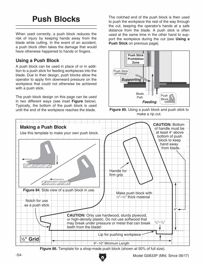
-54- Model G0833P (Mfd. Since 06/17)
Figure 86. Template for a shop-made push block (shown at 50% of full size).
9"−10" Minimum Length
Lip for pushing workpiece
Handle for firm grip
Make push block with1⁄2"–3⁄4" thick material
1/4"–1/2"
4"
Notch for useas a push stick
1⁄2" Grid
CAUTION: Only use hardwood, sturdy plywood, or high-density plastic. Do not use softwood that may break under pressure or metal that can break teeth from the blade!
CAUTION: Bottom of handle must be at least 4" above bottom of push block to keep hand away from blade.
Figure 84. Side view of a push block in use.
When used correctly, a push block reduces the risk of injury by keeping hands away from the blade while cutting. In the event of an accident, a push block often takes the damage that would have otherwise happened to hands or fingers.
Using a Push BlockA push block can be used in place of or in addi-tion to a push stick for feeding workpieces into the blade. Due to their design, push blocks allow the operator to apply firm downward pressure on the workpiece that could not otherwise be achieved with a push stick.
The push block design on this page can be used in two different ways (see inset Figure below). Typically, the bottom of the push block is used until the end of the workpiece reaches the blade.
Push Blocks
BladePath
Push Stick
PushBlock
Push StickProhibition
Zone
Feeding
Supporting
Figure 85. Using a push block and push stick to make a rip cut.
The notched end of the push block is then used to push the workpiece the rest of the way through the cut, keeping the operator's hands at a safe distance from the blade. A push stick is often used at the same time in the other hand to sup-port the workpiece during the cut (see Using a Push Stick on previous page).
Making a Push BlockUse this template to make your own push block.

Model G0833P (Mfd. Since 06/17) -55-
Note: We recommend cutting hardwood board oversize, then jointing and planing it to correct size to make sure board is square and flat. Only use furniture-grade plywood or kiln-dried hardwood to prevent warping.
3"
3⁄4" Hardwood
51⁄4"
3⁄4" PlywoodLength of TableSaw Rip Fence
Length of TableSaw Rip Fence
Figure 87. Auxiliary fence dimensions.
Making a Narrow-Rip Push Block for an Auxiliary Fence1. Cut a piece of 3⁄4" thick plywood 5 1⁄4" wide
and as long as your table saw fence; cut a piece of 3⁄4" thick hardwood 3" wide and as long as your table saw fence, as shown in Figure 87.
Narrow-Rip Auxiliary Fence & Push Block
There are designs for hundreds of specialty jigs that can be found in books, trade magazines, and on the internet. These types of jigs can greatly improve the safety and consistency of cuts. They are particularly useful during production runs when dozens or hundreds of the same type of cut need to be made.
The narrow-rip auxiliary fence and push block system shown in this section is an example of a specialty jig that can be made to increase the safety of very narrow rip cuts.
2. Pre-drill and countersink eight pilot holes 3⁄8" from bottom of 3" wide board, then secure boards together with eight #8 x 11⁄2" wood screws, as shown in Figure 88.
3⁄4" Plywood
CompletedFence
3⁄4" Hardwood#8 x 11⁄2"Wood Screw
Figure 88. Location of pilot holes.
5 5⁄8"
15"
5 1⁄4"
12 1⁄2"
2 1⁄2"
3⁄8"
Lip
Handle
3⁄8"
5⁄8"2
1⁄2"
Figure 89. Push block dimensions and construction.
3. Using 3⁄4" material you used in previous steps, cut out pieces for push block per dimen-sions shown in Figure 89; for handle, cut a piece 10" long by 5"–9" high and shape it as desired to fit your hand.
4. Attach handle to base with #8 x 11⁄2" wood screws, and attach lip to base with cyanoac-rylate-type wood glue.
Material Needed for Narrow Rip Auxiliary Fence & Push BlockHardwood 3⁄4" x 3" x Length of Fence ................1Plywood 3⁄4" x 51⁄4" x Length of Fence ................1Wood Screws #8 x 11⁄2" ......................................8
Material Needed for Push BlockHardwood or Plywood 3⁄4" x 15" x 55⁄8" ...............1Hardwood or Plywood 3⁄4" x 10" x 5"–9" ............1 Cyanoacrylate Wood Glue .........................VariesWood Screws #8 x 11⁄2" ......................As Needed
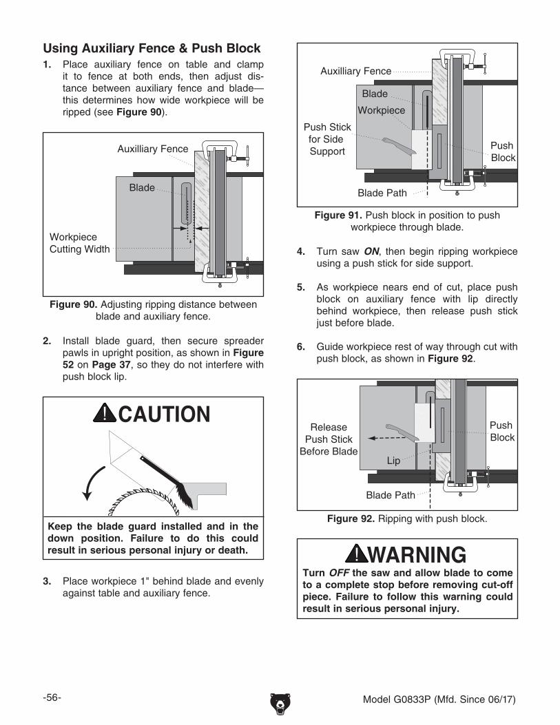
-56- Model G0833P (Mfd. Since 06/17)
Using Auxiliary Fence & Push Block1. Place auxiliary fence on table and clamp
it to fence at both ends, then adjust dis-tance between auxiliary fence and blade—this determines how wide workpiece will be ripped (see Figure 90).
2. Install blade guard, then secure spreader pawls in upright position, as shown in Figure 52 on Page 37, so they do not interfere with push block lip.
Keep the blade guard installed and in the down position. Failure to do this could result in serious personal injury or death.
3. Place workpiece 1" behind blade and evenly against table and auxiliary fence.
Workpiece Cutting Width
Blade
Auxilliary Fence
Figure 90. Adjusting ripping distance between blade and auxiliary fence.
Auxilliary Fence
Blade
Workpiece
Push Stickfor Side Support
Blade Path
Push Block
Figure 91. Push block in position to push workpiece through blade.
4. Turn saw ON, then begin ripping workpiece using a push stick for side support.
5. As workpiece nears end of cut, place push block on auxiliary fence with lip directly behind workpiece, then release push stick just before blade.
6. Guide workpiece rest of way through cut with push block, as shown in Figure 92.
Push Block
Lip
ReleasePush Stick
Before Blade
Blade Path
Figure 92. Ripping with push block.
Turn OFF the saw and allow blade to come to a complete stop before removing cut-off piece. Failure to follow this warning could result in serious personal injury.
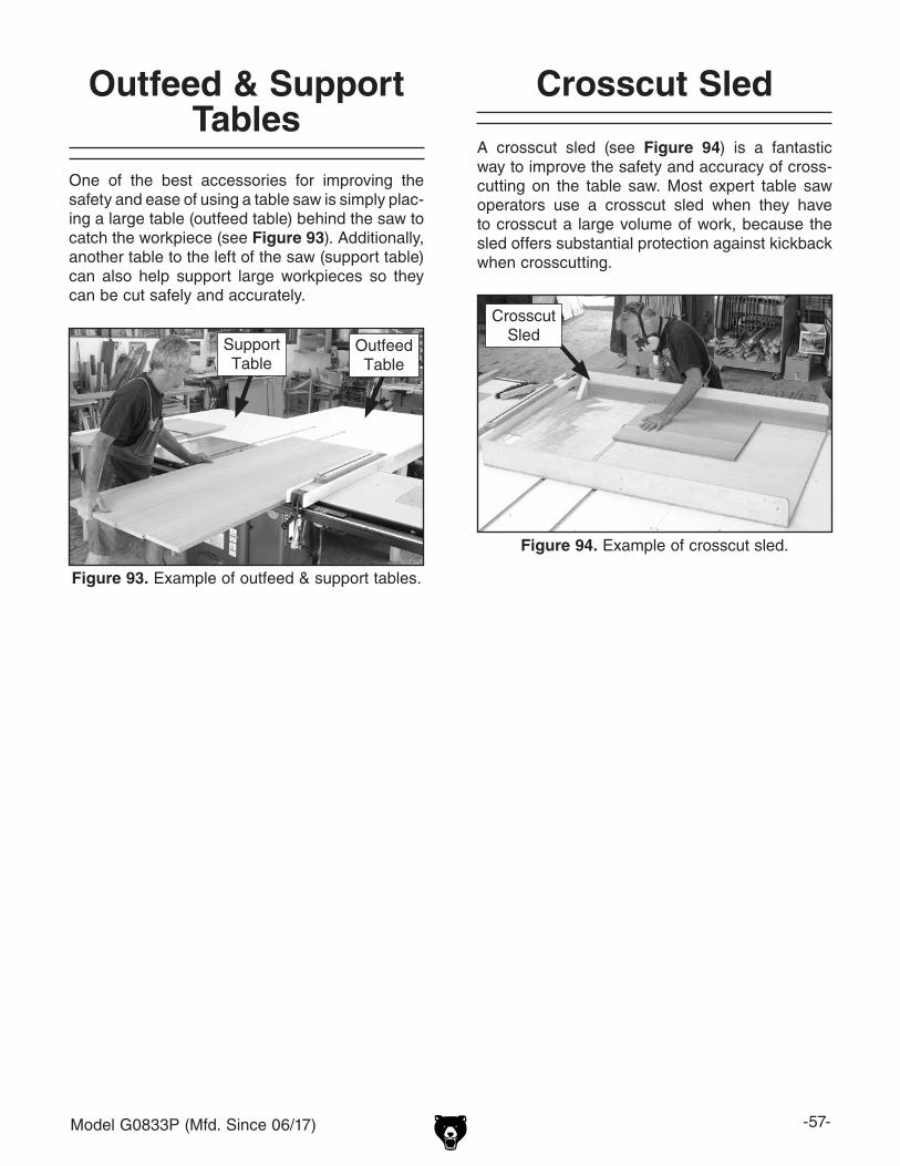
Model G0833P (Mfd. Since 06/17) -57-
A crosscut sled (see Figure 94) is a fantastic way to improve the safety and accuracy of cross-cutting on the table saw. Most expert table saw operators use a crosscut sled when they have to crosscut a large volume of work, because the sled offers substantial protection against kickback when crosscutting.
Figure 94. Example of crosscut sled.
Crosscut Sled
Crosscut Sled
One of the best accessories for improving the safety and ease of using a table saw is simply plac-ing a large table (outfeed table) behind the saw to catch the workpiece (see Figure 93). Additionally, another table to the left of the saw (support table) can also help support large workpieces so they can be cut safely and accurately.
Figure 93. Example of outfeed & support tables.
Outfeed Table
Support Table
Outfeed & Support Tables

-58- Model G0833P (Mfd. Since 06/17)
ACCESSORIES
T23279—Zero Clearance Insert for G0833P
SECTION 6: AFTERMARKET ACCESSORIES FROM GRIZZLY
Installing unapproved accessories may cause machine to malfunction, resulting in serious personal injury or machine damage. To reduce this risk, only install accessories recommended for this machine by Grizzly.
NOTICERefer to our website or latest catalog for additional recommended accessories.
D4206—Clear Flexible Hose 4" x 10'W1034—Heavy-Duty Clear Flex Hose 4" x 10'W1015—Y-Fitting 4" x 4" x 4"W1017—90° Elbow 4"W1019—Hose Coupler (Splice) 4"W1317—Wire Hose Clamp 4"W1007—Plastic Blast Gate 4"W1053—Anti-Static Grounding KitWe've hand picked a selection of commonly used dust collection components for machines with 4" dust ports.
Figure 95. Dust collection accessories.
D4206
W1317
D4216
W1007
W1017
W1053
G1163P—1HP Floor Model Dust CollectorG0710—1HP Wall-Mount Dust CollectorH4340—3.0 Micron Upgrade BagExcellent point-of-use dust collectors that can be used next to the machine with only a small amount of ducting. Specifications: 450 CFM, 7.2" static pressure, 2 cubic foot bag, and 30 micron filter. Motor is 1HP, 110V/220V, 14A/7A.
Figure 96. Point-of-use dust collectors.
Model G0710
Model G1163P
Figure 97. H4756 Dado Blade.
Forrest Dado BladesH4756— 8", 24 Teeth, 1⁄4"–29⁄32" GrooveT23267—8", 24 Teeth, 3⁄16"–1⁄4" GrooveThe world's finest dado head clean cuts all your grooves! No splintering when cross-cutting oak, ply veneers and melamine. Perfect for flat-bottomed grooves. No staggered steps or round bottoms like a wobble-dado leaves! Cuts in all directions - rip, cross-cut, miter, any depth. Cuts all sized grooves 1⁄4" through 29⁄32" increments.
order online at www.grizzly.com or call 1-800-523-4777

Model G0833P (Mfd. Since 06/17) -59-
SECTION 7: MAINTENANCE
Schedule
To prevent serious per-sonal injury from shock or accidental startup, always disconnect power from machine before doing any maintenance.
Cleaning & Protecting
Cleaning the Model G0833P is relatively easy. Vacuum excess wood chips and sawdust, and wipe off the remaining dust with a dry cloth. If any resin has built up, use a resin-dissolving cleaner to remove it.
Protect the unpainted cast-iron table by wiping it clean after every use—this ensures moisture from wood dust does not remain on the bare metal surface. Keep the table rust-free with regular applications of products like G96® Gun Treatment, SLIPIT®, or Boeshield® T-9.
For optimum performance from your machine, follow this maintenance schedule and refer to any specific instructions given in this section.
Daily Check:• Loose mounting bolts/arbor nut.• Damaged saw blade.• Worn or damaged wires.• Any other unsafe condition.
Weekly Maintenance:• Clean table surface and miter slot grooves.• Clean and protect cast-iron table.• Clean rip fence.
Monthly Maintenance:• Clean/vacuum dust buildup from inside cabi-
net and off motors.• Check/replace belt for proper tension, dam-
age or wear (Page 74).
Every 6–12 Months:• Lubricate trunnion slides (Page 60).• Lubricate worm gear and bull gear (Page 60).• Lubricate leadscrew (Page 60).
G5562—SLIPIT® 1 Qt. GelG5563—SLIPIT® 12 Oz. SprayG2871—Boeshield® T-9 12 Oz. SprayG2870—Boeshield® T-9 4 Oz. SprayH3788—G96® Gun Treatment 12 Oz. SprayH3789—G96® Gun Treatment 4.5 Oz. Spray
Figure 98. Recommended products for protect-ing unpainted cast iron/steel parts on machinery.
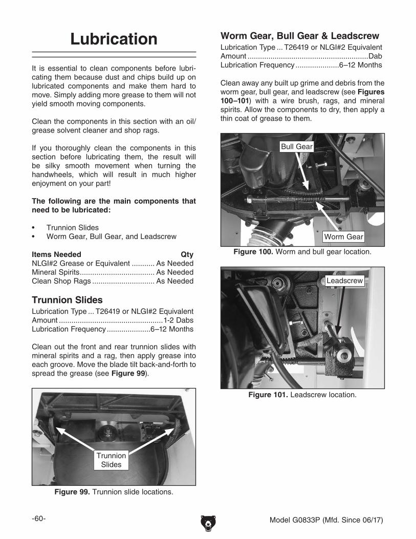
-60- Model G0833P (Mfd. Since 06/17)
Lubrication
It is essential to clean components before lubri-cating them because dust and chips build up on lubricated components and make them hard to move. Simply adding more grease to them will not yield smooth moving components.
Clean the components in this section with an oil/grease solvent cleaner and shop rags.
If you thoroughly clean the components in this section before lubricating them, the result will be silky smooth movement when turning the handwheels, which will result in much higher enjoyment on your part!
The following are the main components that need to be lubricated:
• Trunnion Slides• Worm Gear, Bull Gear, and Leadscrew
Figure 100. Worm and bull gear location.
Bull Gear
Worm Gear
Figure 101. Leadscrew location.
Leadscrew
Clean away any built up grime and debris from the worm gear, bull gear, and leadscrew (see Figures 100–101) with a wire brush, rags, and mineral spirits. Allow the components to dry, then apply a thin coat of grease to them.
Worm Gear, Bull Gear & Leadscrew
Items Needed QtyNLGI#2 Grease or Equivalent ........... As NeededMineral Spirits .................................... As NeededClean Shop Rags .............................. As Needed
Lubrication Type ... T26419 or NLGI#2 EquivalentAmount ..........................................................DabLubrication Frequency .....................6–12 Months
Trunnion SlidesLubrication Type ... T26419 or NLGI#2 EquivalentAmount ..................................................1-2 DabsLubrication Frequency .....................6–12 Months
Clean out the front and rear trunnion slides with mineral spirits and a rag, then apply grease into each groove. Move the blade tilt back-and-forth to spread the grease (see Figure 99).
Figure 99. Trunnion slide locations.
Trunnion Slides

Model G0833P (Mfd. Since 06/17) -61-
Troubleshooting
Symptom Possible Cause Possible SolutionMachine does not start, or power supply breaker immediately trips after startup.
1. Locking pin installed in switch.2. Machine circuit breaker tripped.3. Power supply circuit breaker tripped or fuse
blown.4. Plug/receptacle at fault/wired incorrectly.5. Motor wires connected incorrectly.6. Wiring open/has high resistance.7. START/STOP switch or circuit breaker at
fault.8. Start capacitor at fault.9. Motor at fault.
1. Remove locking pin from START button.2. Reset circuit breaker on switch.3. Ensure circuit is sized correctly and free of shorts.
Reset circuit breaker or replace fuse.4. Test for good contacts; correct the wiring.5. Correct motor wiring connections (Page 76).6. Check/fix broken, disconnected, or corroded wires. 7. Replace switch/circuit breaker.
8. Test/replace if faulty.9. Test/repair/replace.
Machine stalls or is underpowered.
1. Feed rate/cutting speed too fast.2. Workpiece material unsuitable for machine.3. Motor overheated; tripping machine circuit
breaker.4. Blade dull or incorrect for type of cut.5. Belt(s) slipping.6. Motor wired incorrectly.7. Pulleys slipping on shaft or misaligned.
8. Run capacitor at fault.9. Motor bearings at fault.10. Contactor not energized/has poor contacts.11. Centrifugal switch at fault.12. Motor at fault.
1. Decrease feed rate/cutting speed.2. Only cut wood/ensure moisture is below 20%.3. Clean motor/let cool, and reduce workload. Reset
breaker.4. Use correct, sharp blade; reduce feed rate.5. Tension/replace belt(s).6. Wire motor correctly (Page 76).7. Tighten/replace loose pulley; ensure pulleys are
aligned (Page 74)8. Test/repair/replace.9. Test/repair/replace.10. Test all legs for power/replace if faulty.11. Adjust/replace centrifugal switch if available.12. Test/repair/replace.
Machine has vibration or noisy operation.
1. Motor or component loose.
2. Blade at fault.3. Belt(s)/pulley(s) worn, loose, or misaligned.
4. Motor mount loose/broken.5. Machine incorrectly mounted/resting on
floor.6. Arbor pulley loose.7. Motor fan rubbing on fan cover.8. Arbor bearings at fault.9. Motor bearings at fault.
1. Inspect/replace damaged bolts/nuts, and re-tighten with thread-locking fluid.
2. Replace warped/bent blade; resharpen dull blade.3. Inspect/replace belts with new matched set. Realign/
replace shaft, pulley, set screw, and key (Page 74).4. Tighten/replace.5. Tighten mounting bolts; relocate/shim machine.
6. Retighten/replace arbor pulley.7. Fix/replace fan cover; replace loose/damaged fan.8. Replace arbor housing bearings; replace arbor. 9. Test by rotating shaft; grinding/loose shaft requires
bearing replacement.
Review the troubleshooting and procedures in this section if a problem develops with your machine. If you need replacement parts or additional help with a procedure, call our Technical Support. Note: Please gather the serial number and manufacture date of your machine before calling.
SECTION 8: SERVICE

-62- Model G0833P (Mfd. Since 06/17)
Symptom Possible Cause Possible SolutionRip fence does not move smoothly.
1. Rip fence mounted/adjusted incorrectly.
2. Rails dirty or sticky.
1. Remount rip fence. Adjust fence (Page 71) to ensure adjustment screws are not too tight.
2. Clean and wax rails.
Material moves away from fence when ripping.
1. Improper feeding technique.2. Fence not parallel with blade.
1. Learn/use proper feeding technique.2. Adjust fence parallel with blade (Page 70).
Blade not parallel with miter slot.
1. Blade warped/damaged/dull. 1. Replace blade (Page 33).
Blade tilt does not stop at 45°/90°.
1. 45°/90° stop out of adjustment. Sawdust built up in/on trunnions.
1. Adjust 45°/90° stop (Page 63). Remove sawdust from trunnions. Clean and re-lubricate as necessary.
Blade hits table insert when tilting to 45°.
1. Sawdust/debris stuck in trunnion slides.2. Table/trunnion assembly mount position not
correct.3. Miter slot not parallel with blade.
4. Blade incorrectly installed.
1. Clean sawdust or debris out of trunnion slides.2. Adjust table or trunnion mounting position (Page 65).
3. Make miter slot parallel with blade; shim table (Page 65).
4. Correctly install blade (Page 33).
Board binds or burns when feeding through table saw.
1. Blade warped/damaged/dull.2. Too many teeth on blade for cutting type.3. Fence not parallel to blade.4. Miter slot not parallel with blade.5. Riving knife or spreader not correctly aligned
with blade.6. Spreader not correctly aligned with blade.
1. Replace blade (Page 33).2. Change blade to one with fewer teeth.3. Adjust fence parallel with blade (Page 70). 4. Make miter slot parallel with blade (Page 65).5. Adjust riving knife or spreader into alignment with
blade (Page 67).6. Adjust spreader into alignment with blade (Page 67).
Handwheel binds or is difficult to move.
1. Lock knob is tightened.2. Handwheel shaft pins are wedged.
1. Loosen lock knob.2. Remove handwheel and adjust shaft pins.
Blade too close to insert.
1. Blade or arbor washers incorrectly installed on arbor.
2. Table/trunnion assembly mount position not correct.
1. Verify blade and arbor washers are correctly installed in the required positions.
2. Adjust table or trunnion mounting position (Page 65).
Blade will not go beneath table surface.
1. Roll pin/set screw in worm gear contacting geared trunnion.
1. Tighten roll pins and set screws in the worm gear.
Blade will not move up or down.
1. Set screw on worm gear is loose or missing. 1. Tighten or replace set screw.
Too much sawdust blown back toward operator.
1. Blade guard removed.
2. Too many air leaks in cabinet for proper dust collection.
3. Dust collection system clogged or lacks required CFM at machine.
4. Fence not parallel with blade (pressure at blade backside).
5. Miter slot not parallel with blade.
1. Re-install blade guard for maximum safety and dust control (Page 34).
2. Seal leaks in cabinet or around blade guard dust port.
3. Remove clog; revise ducting layout for improved suction; use a different dust collector.
4. Adjust fence parallel with blade (Page 70).
5. Make miter slot parallel with blade (Page 65).
Workpiece catches on table/dado insert or table throat during cutting operation.
1. Table/dado insert out of adjustment. 1. Adjust table/dado insert so it is perfectly flush with table surface (Page 72).

Model G0833P (Mfd. Since 06/17) -63-
Blade Tilt Stops
The table saw features stop collars that stop the blade exactly at 45° and 90° when tilting it with the handwheel. The stops have been set at the factory and should require no adjustments, unless you notice that your cuts are not accurate.
Note: The tilt scale reads "0" when the blade is 90° to the table.
Tools Needed Qty90° Square ........................................................ 145° Square ........................................................ 1Hex Wrench 2.5mm ........................................... 1Hex Wrench 3mm .............................................. 1
Setting 90° Stop Collar1. DISCONNECT MACHINE FROM POWER!
2. Raise blade as high as it will go, then tilt it toward 0° until it stops and cannot be tilted any more.
3. Place 90° square against table and blade so it contacts blade evenly from bottom to top, as shown in Figure 102. Make sure blade tooth does not obstruct placement of square.
—If blade is 90° to table, then adjustments do not need to be made. Make sure tilt indica-tor arrow shown in Figure 103 points to 0° mark on scale. Adjust position by loosening button head screw, moving indicator with your fingers, then tightening screw.
Figure 102. Checking blade at 90°.
Table
90° SquareBlade
—If blade is not 90° to table, you will need to adjust 90° stop collar. Proceed to next step.
4. Tilt blade away from 0° by about 5°, so there is room for 90° stop collar to move.
5. Open motor door, loosen set screws shown in Figure 104, then thread 90° stop collar one turn away from trunnion bracket. This will allow you to square blade in next step.
Figure 103. Tilt indicator arrow.
Indicator
6. Place square against blade, as shown in Figure 102, then adjust blade until it is per-fectly square to table.
7. Without turning blade tilt leadscrew, finger-tighten 90° collar against trunnion bracket, then tighten two set screws to secure collar position.
Figure 104. 90° stop collar and set screws.
Set Screws
90° Stop Collar
Trunnion Bracket

-64- Model G0833P (Mfd. Since 06/17)
Setting 45° Stop Collar1. DISCONNECT MACHINE FROM POWER!
2. Raise blade as high as it will go, then tilt it towards 45° until it stops and cannot be tilted any more.
3. Place a 45° square against table and blade so it contacts blade evenly from bottom to top, as shown in Figure 105. Make sure a blade tooth does not obstruct placement of square.
Figure 105. Checking blade at 45°.
Blade
45° Square
Table
—If blade is 45° to table, then adjustments do not need to be made.
—If blade is not 45° to table, you will need to adjust 45° stop collar. Proceed to next step.
4. Tilt blade to 30°, so there is room for stop collar to move.
8. Repeat Steps 2–3 to verify that collar adjust-ment you made was correct. When adjust-ment is satisfactory, close motor door.
6. Place a 45° square against blade, as shown in Figure 105, then adjust blade until it is exactly 45° to table.
7. Without turning blade tilt leadscrew, finger-tighten 45° stop collar against trunnion brack-et, then tighten two set screws to secure col-lar position.
8. Repeat Steps 2–3 to verify that collar adjust-ment you made was correct. When adjust-ment is satisfactory, close right access cover.
5. Open right access cover, loosen set screws on 45° stop collar (see Figure 106), then turn collar one turn away from trunnion bracket. This will allow you to adjust blade to exactly 45° in next step.
Figure 106. Location of 45° stop collar (right access cover removed).
Trunnion Bracket
Set Screws
45° Stop Collar

Model G0833P (Mfd. Since 06/17) -65-
3. With end of adjustable square just touching tip, lock square in place. Now, mark car-bide tip with a marker where you made this measurement.
Miter Slot to Blade Parallelism
Your table saw will give the best results if the miter slot and the rip fence are adjusted paral-lel to the blade. If either of these are not exactly parallel, your cuts and your finished work will be lower in quality, but more importantly, the risk of kickback will be increased.
Tools Needed QtyAdjustable Square ............................................. 1Marker ............................................................... 1Metal Shim Stock .............................. As Needed Hex Wrench 6mm .............................................. 1
To adjust blade parallel to miter slot:
1. DISCONNECT SAW FROM POWER!
2. Tilt blade to 0°, then use an adjustable square to measure distance from miter slot to a car-bide tip on blade, as shown in Figure 107. Make sure that face of adjustable square is even along miter slot.
The saw blade is sharp. Use extra care or wear gloves when handling the blade or working near it.
4. Rotate marked blade tip to other end of table insert.
5. Slide adjustable square down to other end of table insert and compare distance from marked blade tip to end of adjustable square, as shown in Figure 108.
— If blade tip measurement is same on both sides, go to Step 8.
— If blade tip does not touch end of adjust-able square similar to first measurement, table will need to be adjusted. Proceed to Step 6.
Blade tilted to 0º
Front
B
STEP B
Figure 108. Measuring distance from miter slot to carbide tip on opposite side of table insert.
Figure 107. Example of adjusting blade to miter slot.
Blade tilted to 0º
Front
STEP A

-66- Model G0833P (Mfd. Since 06/17)
6. Loosen (4) table mounting bolts securing table top to base (see Figure 109), and lightly tap table in direction needed to square table to blade.
8. Tilt blade to 45° and recheck miter slot-to-blade parallelism.
— If blade is still parallel with miter slot, no additional adjustments need to be made.
— If blade is parallel with miter slot at 0° but not at 45°, one end of table will need to be shimmed higher with metal shim stock. Continue to Step 9.
9. Loosen (4) table mounting bolts from Step 6.
Mounting Bolts
Figure 109. Location of table mounting bolts (table omitted for clarity).
7. Repeat Steps 2–6 until blade and miter slot are parallel, then retighten table mounting bolts.
10. Refer to Figures 110–111 for shim place-ment. If distance A is shorter than B, shim(s) will need to be placed under corners #1 and #2. If distance of B is shorter than A, shim(s) will need to be placed under corner #3. Very thin shim stock works well.
Figure 110. Shim procedure diagram A.
STEP A
Front
#1
#2
#3
Figure 111. Shim procedure diagram B.
#1
#2
#3 Front
STEP B

Model G0833P (Mfd. Since 06/17) -67-
11. Tighten one table mounting bolt a small amount and then repeat with the others, tightening each down the same amount. Continue this process with all the bolts, tight-ening them a little each time until they are all secure.
12. Now recheck blade to miter slot at 0° and 45° by repeating Steps 2-5.
— If distance of A and B are equal, continue to Step 13.
— If distances are not equal, repeat Steps 9–12.
13. Once miter slot is adjusted to blade, recheck all measurements and be sure table mount-ing bolts are secure.
Note: If you remove the table in the future, note the shim placement and reassemble them exactly how they came apart.
Spreader or Riving Knife Alignment
Checking AlignmentThe blade guard spreader and riving knife must be aligned with the blade when installed. If the spreader/riving knife is not aligned with the blade, then the workpiece will before forced sideways during the cut, which will increase the risk of kick-back.
Tools Needed QtyStraightedge ...................................................... 1
To check spreader/riving knife alignment:
1. DISCONNECT MACHINE FROM POWER!
2. Raise saw blade to maximum height so you have easy working access.
3. Place straightedge against side of blade and spreader/riving knife at top and bottom, as shown in Figure 112. Spreader/riving knife should be parallel with blade along its length at both positions, and in "Alignment Zone," as shown in Figure 113.
Figure 112. Checking top and bottom riving knife parallelism with blade.
Top Alignment
Bottom Alignment

-68- Model G0833P (Mfd. Since 06/17)
Figure 113. Spreader/riving knife alignment zone.
AlignmentZone
Spreader or Riving Knife
Blade
— If spreader/riving knife is not parallel with blade and inside alignment zone, then it needs to be adjusted. Proceed to Adjusting Alignment instructions.
— If spreader/riving knife is not parallel with the blade at either the top or bottom, it may be bent.
4. Remove spreader/riving knife and place it on flat surface and check to see if spreader/riv-ing knife lays evenly along its length.
— If spreader/riving knife does not lay evenly, proceed to Adjusting Bent Spreader/Riving Knife on Page 69.
Adjusting AlignmentThe spreader/riving knife mounting position can be adjusted into alignment with the blade using the set screws on the spreader/riving knife mount-ing block.
Tool Needed QtyHex Wrench 2.5mm ........................................... 1
To adjust spreader/riving knife position:
1. DISCONNECT MACHINE FROM POWER!
2. Remove table insert.
3. Loosen (2) cap screws on mounting block, then adjust either top or bottom control set screws or side control set screws (see Figure 114) to move it the needed direction.
Top and Bottom Control: To move the top of the spreader/riving knife right or left (and the bottom of the spreader/riving knife in the opposite direction), adjust the top and bottom pair of set screws on the mounting block an equal amount in the opposite direction.
Side Control: To move the front of the
spreader/riving knife left or right (and the rear of the spreader/riving knife in the opposite direction), adjust each pair of side control set screws an equal amount in the opposite direction.
Note: To adjust how tightly the mounting block holds the spreader/riving knife, adjust the center screw.
Figure 114. Set screws for adjusting spreader/riving knife position.
AlignmentZone
MisalignedSplitter or
Riving Knife
Blade
Adjustment BlockTop Control
Side
ControlS
ide
Con
trol
Bottom Control
Cap Screws
Center Screw
Cap Screws
Set Screw(1 of 4)

Model G0833P (Mfd. Since 06/17) -69-
Adjusting Bent Spreader/Riving Knife1. DISCONNECT MACHINE FROM POWER!
2. Bend spreader or riving knife by hand while installed, then follow Steps 1–3 in Checking Alignment on Page 67 to determine if it is par-allel with blade and inside "Alignment Zone" (refer to Figure 112 Checking Alignment on Page 67).
— If this doesn't work, remove it to straighten.
— If you cannot straighten it properly, replace it.
4. Re-install table insert.
5. Follow Checking Alignment, Steps 1–3.
— If spreader/riving knife is in alignment zone, no additional steps are necessary.
—If spreader/riving knife is still not in align-ment zone, continue adjusting set screws on mounting block as necessary to cor-rectly position spreader/riving knife.
6. Tighten (2) cap screws on mounting block to secure spreader/riving knife adjustment.
Fence Adjustments
There are four main adjustments for the fence: height off the table, squareness, parallelism with the miter slot, and clamping pressure. These adjustments are interconnected and some repeti-tion may be needed when adjusting.
Tools Needed QtyHex Wrench 6mm .............................................. 1Square ............................................................... 1Felt-Tipped Marker ............................................ 1
Figure 115. Location of screws used to adjust fence parallelism and clamping pressure.
Rear Set Screws
Front Lock Nutsand Adjustment Screws
Height and SquareThe fence should be adjusted high enough off the table so that it does not drag across the surface or allow wood chips to get caught between the fence and table. Also, the fence face must be square to the table in order to produce accurate cuts.
To check/adjust fence height and squareness to table:
1. DISCONNECT MACHINE FROM POWER!
2. Remove fence from saw and place it on a flat surface.
3. Unscrew front lock nuts and adjustment screws shown in Figure 115 until they are barely threaded into fence flange.
4. Back out rear set screws until they are just threaded into fence flange (see Figure 115).

-70- Model G0833P (Mfd. Since 06/17)
Figure 116. Fence components used to adjust fence height and squareness to table.
Lock Nut
Fence Flange
Knob(1 of 3)
Rear RailFoot
Top Adjustment Screws
5. Install fence onto table, then loosen fence knobs (see Figure 116), pull fence up from center, and tighten each knob.
6. Loosen top lock nuts on fence flange and lock nut on rear rail foot, shown in Figure 116.
9. Loosen top lock nuts and adjust top screws (see Figure 116) to make fence face 90° to table, then tighten lock nuts.
Figure 118. Example of aligning fence to miter slot.
FenceFaceMiter
Slots
Top View
OverlapSide View (Bad)
FlushSide View (Good)
A
B
Set screws on the rear side of the fence flange position the fence parallel to the blade and adjust the clamping pressure to hold fence securely. Before starting this procedure, make sure the blade is parallel with the miter slot.
To adjust fence parallelism and clamping pressure:
1. DISCONNECT MACHINE FROM POWER!
2. Lock fence, tap front side with your fist, and check to see if it moved sideways over table.
—If fence did not move, proceed to Step 5.
—If fence moved, remove it from table and proceed to Step 3.
3. Turn each rear set screw (see Figure 115 on Page 69) in 1⁄6th of a turn.
4. Re-install fence and repeat Step 2.
5. Slide fence up against right-hand edge of miter slot, as shown in Figure 118, and lock it in place.
Parallelism & Clamping Pressure
Figure 117. Checking if fence is square to table.
90° SquareFence
Table
7. Turn top adjustment screws and rear foot screw so there is approximately 1⁄16" clear-ance between bottom of fence and table, front-to-back and side-to-side, then tighten lock nuts.
8. Place square on table and against face of fence, as shown in Figure 117, to check if fence is square to table.
— If fence is square to table, proceed to Parallelism & Clamping Pressure.
— If fence is not square to the table, proceed to Step 9.

Model G0833P (Mfd. Since 06/17) -71-
6. Examine how fence lines up with miter slot along its length.
—If fence and miter slot are flush from front to rear, as shown in Figure 118A, proceed to Step 8.
—If rear of fence overlaps miter slot, as shown in Figure 118B, fence is mis-aligned. Proceed to Step 7.
7. Remove fence, then alternately loosen and tighten rear fence set screws in equal amounts to adjust rear of fence until it is par-allel with miter slot.
8. Loosen both front lock nuts (see Figure 115 on Page 69). Tighten adjustment screws so they just touch fence tube, back off screws 1⁄2 turn, then tighten lock nuts.
Some woodworkers prefer to offset the rear of the fence 1/64" from the blade, as shown in Figure 119, to help prevent the workpiece from binding and burning.
The argument is that this offset adjustment reduc-es the chance of kickback by alleviating potential binding that may occur between the backside of the blade and fence. The tradeoff is slightly less accurate cuts.
Figure 119. Adjusting fence with a 1⁄64" offset.
X"
X" + 1/64"
Extra Spaceto Prevent Binding
(Optional)
X = Your Measurement
Blade
Optional Offset Fence Adjustment
To offset fence:
1. DISCONNECT MACHINE FROM POWER!
2. With a felt tip pen, mark one saw tooth and rotate blade so this tooth is positioned at back of table insert.
3. Place fence on table, and clamp fence to table.
4. Measure distance between tooth and fence face, as shown in Figure 119.
5. Remove fence, and adjust rear set screws as previously discussed to achieve an offset of 1/64" between marked tooth and fence face.
6. Re-install fence and measure distance again between marked tooth and fence face. The rear measurement should be 1/64" greater than previously measured in Step 4.
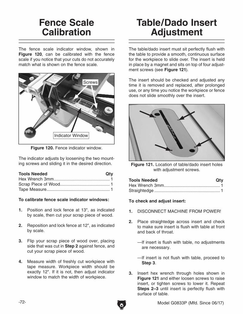
-72- Model G0833P (Mfd. Since 06/17)
Fence Scale Calibration
The fence scale indicator window, shown in Figure 120, can be calibrated with the fence scale if you notice that your cuts do not accurately match what is shown on the fence scale.
The indicator adjusts by loosening the two mount-ing screws and sliding it in the desired direction.
Tools Needed QtyHex Wrench 3mm .............................................. 1Scrap Piece of Wood......................................... 1Tape Measure .................................................... 1
To calibrate fence scale indicator windows:
1. Position and lock fence at 13", as indicated by scale, then cut your scrap piece of wood.
2. Reposition and lock fence at 12", as indicated by scale.
3. Flip your scrap piece of wood over, placing side that was cut in Step 2 against fence, and cut your scrap piece of wood.
4. Measure width of freshly cut workpiece with tape measure. Workpiece width should be exactly 12". If it is not, then adjust indicator window to match the width of workpiece.
Figure 120. Fence indicator window.
Screws
Indicator Window
Table/Dado Insert Adjustment
The table/dado insert must sit perfectly flush with the table to provide a smooth, continuous surface for the workpiece to slide over. The insert is held in place by a magnet and sits on top of four adjust-ment screws (see Figure 121).
The insert should be checked and adjusted any time it is removed and replaced, after prolonged use, or any time you notice the workpiece or fence does not slide smoothly over the insert.
Tools Needed QtyHex Wrench 3mm .............................................. 1Straightedge ...................................................... 1
Figure 121. Location of table/dado insert holes with adjustment screws.
To check and adjust insert:
1. DISCONNECT MACHINE FROM POWER!
2. Place straightedge across insert and check to make sure insert is flush with table at front and back of throat.
— If insert is flush with table, no adjustments are necessary.
— If insert is not flush with table, proceed to Step 3.
3. Insert hex wrench through holes shown in Figure 121 and either loosen screws to raise insert, or tighten screws to lower it. Repeat Steps 2–3 until insert is perfectly flush with surface of table.

Model G0833P (Mfd. Since 06/17) -73-
Miter Gauge Adjustments
The miter gauge can be adjusted so it is perpen-dicular to the blade and snug in the T-slot.
Tools Needed Qty90° Square ........................................................ 145° Square ........................................................ 1Hex Wrench 2mm .............................................. 1Hex Wrench 2.5mm ........................................... 1Hex Wrench 4mm .............................................. 1
Checking/Setting 90° Stops1. DISCONNECT MACHINE FROM POWER!
2. Slide miter gauge into T-slot on table.
3. Loosen miter gauge lock knob, pull out posi-tive stop knob, then pivot miter gauge body to 90° so stop knob springs into position (see Figure 122).
Figure 123. Checking 90° stop on miter gauge.
Square
Miter Gauge
Blade
Figure 122. Set screws for adjusting miter bar in miter slot.
Set Screws
Lock Knob Indicator Screw
Positive Stop Knob
4. Place square evenly against face of miter gauge and blade, as shown in Figure 123.
— If square does not touch miter body and blade body evenly at same time, then pro-ceed to Step 5.
5. Loosen button head cap screws on positive stop knob block (see Figure 124), adjust miter body until it is flush with square, then tighten screws.
— If square touches miter body and body of blade (not the teeth) evenly at same time, then it is square to blade and 90° stop is set correctly. No further adjustments are necessary.
6. Loosen indicator screw on top of miter bar, adjust pointer to 0°, then tighten screw.
Adjusting Miter Bar TightnessThe miter bar can be adjusted so it fits more tightly in the miter slot. To adjust the miter bar tightness, adjust the set screws shown in Figure 122 as needed. Bar should slide with little resistance.
Figure 124. Screws for adjusting miter body.
Positive Stop Knob Block
Button Head Cap Screws

-74- Model G0833P (Mfd. Since 06/17)
Belt Tension & Replacement
Tool Needed QtyHex Wrench 6mm .............................................. 1
Tensioning Belt1. DISCONNECT MACHINE FROM POWER!
2. Raise blade completely, then open the motor door.
3. Loosen cap screw on motor shown in Figure 125, and pivot motor up and down to make sure that it is movable.
4. Press down on motor with one hand to keep belt tension tight and tighten cap screw.
5. Press belt in center to check belt tension. The belt is correctly tensioned when there is approximately 1⁄4" deflection when it is pushed with moderate pressure, as shown in Figure 126.
The drive belt stretches slightly as the saw is used. Most of the belt stretching will happen dur-ing the first 16 hours of use, but it may continue through continued use. If you notice that the belt is slipping, it will need to be tensioned. If the belt is cracked, frayed, or shows other signs of excessive wear, it will need to be replaced.
Replacing Belt1. DISCONNECT MACHINE FROM POWER!
2. Raise blade completely, then open motor door.
3. Loosen cap screw that secures motor (see Figure 125) and lift motor fully to remove ten-sion on belt. Tighten cap screw to hold motor in this position, then roll belt off of the arbor and motor pulleys.
4. Install new belt onto pulleys, loosen cap screw, then lower motor.
5. Press down on motor with one hand to keep belt tension tight and tighten cap screw.
6. Follow Step 5 in the Tensioning Belt sub-
section on this page to check V-belt tension.
7. Close motor door.
PulleyDeflection
Pulley
Figure 126. Checking belt tension.
1⁄4"
— If there is more than 1⁄4" deflection when belt is pushed with moderate pressure, loosen cap screw, push motor downward, then tighten cap screw.
6. Close motor door.
Figure 125. Location of cap screw for adjusting belt tension.
Belt
Cap Screw

Model G0833P (Mfd. Since 06/17) -75-
SHOCK HAZARD. Working on wiring that is con-nected to a power source is extremely dangerous. Touching electrified parts will result in personal injury including but not limited to severe burns, electrocution, or death. Disconnect the power from the machine before servicing electrical com-ponents!
MODIFICATIONS. Modifying the wiring beyond what is shown in the diagram may lead to unpre-dictable results, including serious injury or fire. This includes the installation of unapproved after-market parts.
WIRE CONNECTIONS. All connections must be tight to prevent wires from loosening during machine operation. Double-check all wires dis-connected or connected during any wiring task to ensure tight connections.
CIRCUIT REQUIREMENTS. You MUST follow the requirements at the beginning of this manualwhen connecting your machine to a power source.
WIRE/COMPONENT DAMAGE. Damaged wires or components increase the risk of serious per-sonal injury, fire, or machine damage. If you notice that any wires or components are damaged while performing a wiring task, replace those wires or components.
MOTOR WIRING. The motor wiring shown inthese diagrams is current at the time of printingbut may not match your machine. If you find thisto be the case, use the wiring diagram inside the motor junction box.
CAPACITORS/INVERTERS. Some capacitorsand power inverters store an electrical charge for up to 10 minutes after being disconnected from the power source. To reduce the risk of being shocked, wait at least this long before working on capacitors.
EXPERIENCING DIFFICULTIES. If you are expe-riencing difficulties understanding the information included in this section, contact our Technical Support at (570) 546-9663.
Wiring Safety Instructions
The photos and diagrams included in this section are best viewed in color. You can view these pages in color at www.grizzly.com.
These pages are current at the time of printing. However, in the spirit of improvement, we may make chang-es to the electrical systems of future machines. Compare the manufacture date of your machine to the one stated in this manual, and study this section carefully.
If there are differences between your machine and what is shown in this section, call Technical Support at (570) 546-9663 for assistance BEFORE making any changes to the wiring on your machine. An updated wiring diagram may be available. Note: Please gather the serial number and manufacture date of your machine before calling. This information can be found on the main machine label.
SECTION 9: WIRINGmachine
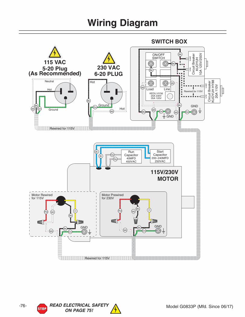
-76- Model G0833P (Mfd. Since 06/17)READ ELECTRICAL SAFETY ON PAGE 75!
Wiring Diagram
Load LineKEDU HY56
20A 230V35A 120V
Neutral
Hot
Ground
115 VAC5-20 Plug
(As Recommended)
115V/230VMOTOR
SWITCH BOX
Motor Rewired for 115V
Motor Prewired for 230V
RunCapacitor
40MFD450VAC
GND
GND
Circ
uit B
reak
erK
UO
YU
H10
A 1
25V
/250
VON/OFFSWITCH
GroundHot
Hot
6-20 PLUG230 VAC
Rewired for 115V
StartCapacitor
200–240MFD250VAC
GND
Rewired for 115V
Line
Load
GND
Circ
uit B
reak
erK
UO
YU
H H
Y88
20A
110
V
Line
Load
Rewired for 115V

Model G0833P (Mfd. Since 06/17) -77-READ ELECTRICAL SAFETY ON PAGE 75!
Electrical Components
Figure 127. Motor capacitors.
Figure 128. Motor junction box.
Figure 129. Switch box components.
Capacitors Circuit Breaker
ON/OFF Switch
Motor Junction Box

-78- Model G0833P (Mfd. Since 06/17)
Body
SECTION 10: PARTSWe do our best to stock replacement parts when possible, but we cannot guarantee that all parts shown are available for purchase. Call (800) 523-4777 or visit www.grizzly.com/parts to check for availability.
1
1
5
2 3 4 76
8
4 3 2
11
10
9 141516
13
17
132324
23
12
36
26
18
22
21 2019
25
30
27 28 2928
31
32
34 3335
REF PART # DESCRIPTION REF PART # DESCRIPTION1 P0833P001 EXTENSION WING 19 P0833P019 HEX NUT M5-.82 P0833P002 CAP SCREW M10-1.5 X 30 20 P0833P020 FLAT WASHER 5MM3 P0833P003 LOCK WASHER 10MM 21 P0833P021 LOCK WASHER 5MM4 P0833P004 FLAT WASHER 10MM 22 P0833P022 BUTTON HD CAP SCR M5-.8 X 125 P0833P005 TABLE INSERT (STANDARD) 23 P0833P023 LEADSCREW BRACKET6 P0833P006 FLAT HD CAP SCR M5-.8 X 10 24 P0833P024 BUTTON HD CAP SCR M5-.8 X 167 P0833P007 TABLE INSERT MAGNET 25 P0833P025 LOCK NUT M8-1.258 P0833P008 MAIN TABLE 26 P0833P026 TILT SCALE9 P0833P009 MOTOR COVER 27 P0833P027 LOCK NUT M3-.510 P0833P010 INT TOOTH WASHER 6MM 28 P0833P028 UPPER AND LOWER HINGE11 P0833P011 KNOB M6-1 29 P0833P029 FLAT HD CAP SCR M3-.5 X 1212 P0833P012 RIVETED NUT M6-1 X 15 30 P0833P030 STRAIN RELIEF TYPE-3 M18-1.513 P0833P013 HEX BOLT M8-1.25 X 25 31 P0833P031 TABLE INSERT (DADO)14 P0833P014 FLAT WASHER 8MM 32 P0833P032 SET SCREW M5-.8 X 815 P0833P015 LOCK WASHER 8MM 33 P0833P033 FLAT WASHER 6MM16 P0833P016 CAP SCREW M8-1.25 X 25 34 P0833P034 DUST PORT 4" X 1-1/2"17 P0833P017 CABINET 35 P0833P035 BUTTON HD CAP SCR M6-1 X 1218 P0833P018 ACCESS COVER 36 P0833P036 LOCK NUT M8-1.25
BUY PARTS ONLINE AT GRIZZLY.COM!Scan QR code to visit our Parts Store.

Model G0833P (Mfd. Since 06/17) -79-
Trunnion
101 102
103104
105 106107
108109
110
111
112113
117108109
118
120
121
126
127 128 130129
122 123 173 103
198
135
145
133104143132
123
174
174
175176
175
177
135
178
108
197
179
180182 181 183
184
185
186
187
188
192191
190189
180
188
187 186
102194195
193
120119169
170
172 120
196 115
201
134
136 137138139108
140139108135
141
142 146
146149
150
151152
153
154155
156157
159108
160158
148162
161
164
167166
165163120
124107 108 109 125
144
104143
104131
122
115
123
200
103199
119 120
201
115
119204
201
203
168
202
202
114115
116
106-2
106-1106-3
106-4
106-8
106-7106-5
106-6
106-10106-9 106-11
147
171
205115

-80- Model G0833P (Mfd. Since 06/17)
Trunnion Parts ListREF PART # DESCRIPTION REF PART # DESCRIPTION101 P0833P101 LOCK NUT M16-2 148 P0833P148 SPRING BRACKET102 P0833P102 FLAT WASHER 16MM 149 P0833P149 FLANGE RING103 P0833P103 CAP SCREW M8-1.25 X 20 150 P0833P150 FLAT HD CAP SCR M5-.8 X 50104 P0833P104 LOCK WASHER 8MM 151 P0833P151 SAW BLADE 10" X 40T 105 P0833P105 FLAT WASHER 8MM 152 P0833P152 ARBOR FLANGE106 P0833P106 MOTOR 2HP 110V/220V 1-PH 153 P0833P153 ARBOR NUT M16-2106-1 P0833P106-1 MOTOR FAN COVER 154 P0833P154 KNURLED KNOB106-2 P0833P106-2 MOTOR FAN 155 P0833P155 SPREADER ADJUSTMENT BLOCK106-3 P0833P106-3 START CAPACITOR COVER 156 P0833P156 COMPRESSION SPRING106-4 P0833P106-4 S CAPACITOR 200-240M 250V 1-1/2 X 2-3/4 157 P0833P157 SPACER106-5 P0833P106-5 RUN CAPACITOR COVER 158 P0833P158 LOCKING PIN 6 X 26106-6 P0833P106-6 R CAPACITOR 40M 450V 2 X 4 159 P0833P159 SPREADER CLAMPING PLATE106-7 P0833P106-7 MOTOR JUNCTION BOX 160 P0833P160 CAP SCREW M6-1 X 25106-8 P0833P106-8 CONTACT PLATE 161 P0833P161 BUTTON HD CAP SCR M6-1 X 20106-9 P0833P106-9 CENTRIFUGAL SWITCH 162 P0833P162 CONNECTING PLATE106-10 P0833P106-10 BALL BEARING 6203ZZ (FRONT) 163 P0833P163 LOCK NUT M6-1106-11 P0833P106-11 BALL BEARING 6204ZZ (REAR) 164 P0833P164 BUTTON HD CAP SCR M5-.8 X 16107 P0833P107 CAP SCREW M6-1 X 16 165 P0833P165 HEX NUT M5-.8108 P0833P108 LOCK WASHER 6MM 166 P0833P166 EXTENSION SPRING109 P0833P109 FLAT WASHER 6MM 167 P0833P167 SHOULDER SCREW M6-1 X 16, 6 X 12110 P0833P110 ARBOR PULLEY 168 P0833P168 DUST COLLECTOR CASE111 P0833P111 POLY V-BELT 150PJ6 169 P0833P169 CAP SCREW M5-.8 X 12112 P0833P112 BUSHING 170 P0833P170 POINTER113 P0833P113 BALL BEARING 6203-2RS 171 P0833P171 BUTTON HD CAP SCR M5-.8 X 12114 P0833P114 KEY 6 X 6 X 20 172 P0833P172 BUTTON HD CAP SCR M4-.7 X 8115 P0833P115 SET SCREW M6-1 X 8 173 P0833P173 MOTOR LOCATING SHAFT116 P0833P116 MOTOR PULLEY 174 P0833P174 STOP COLLAR117 P0833P117 HEX BOLT M6-1 X 16 175 P0833P175 INT RETAINING RING 24MM118 P0833P118 LOCK NUT M5-.8 176 P0833P176 TILT LEADSCREW NUT119 P0833P119 LOCK WASHER 5MM 177 P0833P177 TILT LEADSCREW BASE120 P0833P120 FLAT WASHER 5MM 178 P0833P178 ROLL PIN 4 X 16121 P0833P121 ARBOR LOCK 179 P0833P179 TILT LEADSCREW122 P0833P122 HEX BOLT M8-1.25 X 40 180 P0833P180 ROLL PIN 4 X 20123 P0833P123 HEX NUT M8-1.25 181 P0833P181 FLAT WASHER 12MM124 P0833P124 HEIGHT LIMIT BLOCK 182 P0833P182 BEARING WASHER125 P0833P125 LOCK NUT M8-1.25 183 P0833P183 EXT RETAINING RING 12MM126 P0833P126 MOTOR MOUNT 184 P0833P184 BEVELED BUSHING127 P0833P127 ARBOR BUSHING 185 P0833P185 FLAT WASHER 12MM128 P0833P128 BALL BEARING 6202-2RS 186 P0833P186 HANDWHEEL TYPE -7 160D X 11.5B-K X M10-1.5129 P0833P129 KEY 5 X 5 X 15 187 P0833P187 HANDWHEEL LOCK KNOB M8-1.25 5-LOBE130 P0833P130 ARBOR 188 P0833P188 HANDWHEEL HANDLE 90L, M10-1.5 X 12131 P0833P131 FLAT WASHER 8MM 189 P0833P189 LOCK NUT M12-1.75132 P0833P132 FRONT TRUNNION 190 P0833P190 FLAT WASHER 12MM133 P0833P133 HEX BOLT M8-1.25 X 45 191 P0833P191 COLLAR134 P0833P134 LIMIT BLOCK 192 P0833P192 ELEVATION SHAFT135 P0833P135 FLAT WASHER 6MM 193 P0833P193 POINTER BASE136 P0833P136 FLAT HD CAP SCR M10-1.5 X 40 194 P0833P194 HANDWHEEL BUSHING137 P0833P137 SPACER 195 P0833P195 COMPRESSION SPRING138 P0833P138 SPACER (NYLON) 196 P0833P196 ELEVATION SHAFT SPACER139 P0833P139 CAP SCREW M6-1 X 35 197 P0833P197 CAP SCREW M6-1 X 20140 P0833P140 SHAFT BRACKET 198 P0833P198 STRAIN RELIEF TYPE-1 3/8"141 P0833P141 MAIN TRUNNION 199 P0833P199 CAP SCREW M5-.8 X 30142 P0833P142 MOTOR SHAFT 200 P0833P200 CAP SCREW M5-.8 X 20143 P0833P143 FLAT WASHER 8MM 201 P0833P201 SET SCREW M6-1 X 20144 P0833P144 REAR TRUNNION 202 P0833P202 HOSE CLAMP 3-1/4"145 P0833P145 ADJUSTMENT SCREW 203 P0833P203 CLEAR HOSE 26" X 3"146 P0833P146 NYLON GASKET 204 P0833P204 HEX NUT M10-1.5147 P0833P147 SPREADER BRACKET 205 P0833P205 ARBOR FLANGE (DADO)

Model G0833P (Mfd. Since 06/17) -81-
Power Switch
221
222229
223
224 225
226227
228229
231
232
233
224X
(for 115V conversion)235
236222-1
REF PART # DESCRIPTION REF PART # DESCRIPTION221 P0833P221 TAP SCREW M3.5 X 19 227 P0833P227 LOCK WASHER 4MM222 P0833P222 S/S SWITCH W/STOP PADDLE KEDU HY56 228 P0833P228 FLAT WASHER 4MM222-1 P0833P222-1 PADDLE SWITCH LOCKOUT PIN 229 P0833P229 CLAMP-ON TERMINAL RING223 P0833P223 SWITCH BOX 231 P0833P231 SWITCH BRACKET224 P0833P224 CIRCUIT BREAKER KUOYUH 88 10A 230V 232 P0833P232 TAP SCREW M3.5 X 10224X P0833P224X CIRCUIT BREAKER KUOYUH 88 20A 115V 233 P0833P233 STRAIN RELIEF TYPE-3 M18-1.5225 P0833P225 CIRCUIT BREAKER NUT M10-1.5 235 P0833P235 POWER CORD 14G 3W 72" 6-20P226 P0833P226 PHLP HD SCR M4-.7 X 8 236 P0833P236 MOTOR CORD 14G 3W 32"

-82- Model G0833P (Mfd. Since 06/17)
Blade Guard301 302 303 304
305
306307
308
309
311 312
313
314
315 316317
318
319320
321
322323324
325
326
331
332333
334
335
336
335
311
312
337
338
339
302 303312A
REF PART # DESCRIPTION REF PART # DESCRIPTION301 P0833P301 FLAT HD CAP SCR M4-.7 X 10 319 P0833P319 ANTI-KICKBACK PAWL302 P0833P302 GUARD SUPPORT (FRONT) 320 P0833P320 SPACER303 P0833P303 GUARD SUPPORT (REAR) 321 P0833P321 BUTTON HD CAP SCR M4-.7 X 6304 P0833P304 FLANGE NUT M4-.7 322 P0833P322 SHOULDER SCREW M5-.8 X 10, 11 X 35305 P0833P305 DUST CHUTE 323 P0833P323 SHOULDER SCREW M5-.8 X 10, 11 X 20306 P0833P306 LEFT GUARD 324 P0833P324 RIGHT GUARD307 P0833P307 TAP SCREW M3.5 X 16 325 P0833P325 TAP SCREW M3 X 10308 P0833P308 SPRING CLAMP 326 P0833P326 RIVING KNIFE309 P0833P309 BLADE GUARD DUST PORT 331 P0833P331 HOSE SUPPORT ARM311 P0833P311 BUTTON HD CAP SCR M4-.7 X 10 332 P0833P332 HEX NUT M6-1312 P0833P312 SIDE GUARD 333 P0833P333 FLAT WASHER 6MM312A P0833P312A COMPLETE BLADE GUARD ASSY 334 P0833P334 WING NUT M6-1313 P0833P313 TORSION SPRING 335 P0833P335 HOSE CONNECTOR 1-1/2"314 P0833P314 PAWL SHAFT 336 P0833P336 DUST HOSE 94" X 1-1/2"315 P0833P315 SPREADER 337 P0833P337 PUSH STICK316 P0833P316 ROLL PIN 4 X 16 338 P0833P338 HEX WRENCH SET 2.5-8MM 6-PC317 P0833P317 PAWL RELEASE HOOK 339 P0833P339 WRENCH 13 X 27MM OPEN-ENDS318 P0833P318 RIVET 4 X 8

Model G0833P (Mfd. Since 06/17) -83-
Miter Guage
401
402
403
404
405
406
407
408
409
410
411
412
413
414
415
416417
418
419
REF PART # DESCRIPTION REF PART # DESCRIPTION401 P0833P401 GUIDE BAR 411 P0833P411 COMPRESSION SPRING402 P0833P402 ANGLE SCALE 412 P0833P412 MITER STOP PIN403 P0833P403 RIVET 2.5 X 8 BLIND, STEEL 413 P0833P413 BUTTON HD CAP SCR M4-.7 X 10404 P0833P404 SET SCREW M8-1.25 X 6 414 P0833P414 MITER GAUGE POINTER405 P0833P405 MITER RING 415 P0833P415 FLAT WASHER 4MM406 P0833P406 FLAT HD CAP SCR M5-.8 X 8 416 P0833P416 LOCK WASHER 4MM407 P0833P407 MITER BODY PIVOT PIN 417 P0833P417 BUTTON HD CAP SCR M4-.7 X 6408 P0833P408 MITER GAUGE BODY 418 P0833P418 LOCKING HANDLE M8-1.25 X 24409 P0833P409 MITER STOP PIN KNOB 419 P0833P419 FLAT WASHER 8MM410 P0833P410 PIN BLOCK

-84- Model G0833P (Mfd. Since 06/17)
Fence
501
502
503
504505
506
507
508
509
510
511
512
513
514515
519
520
521
522
523
525
502
524
REF PART # DESCRIPTION REF PART # DESCRIPTION501 P0833P501 GLIDE PAD 512 P0833P512 LOCK NUT M10-1.5502 P0833P502 KNURLED NUT M12-1.75 513 P0833P513 BUTTON HD CAP SCR M5-.8 X 8503 P0833P503 SET SCREW M12-1.75 X 16 BRASS 514 P0833P514 FLAT WASHER 5MM504 P0833P504 SET SCREW M12-1.75 X 10 515 P0833P515 FENCE SCALE WINDOW505 P0833P505 HEX BOLT M6-1 X 40 519 P0833P519 FENCE BASE END CAP 50 X 50MM506 P0833P506 CAM LOCK PLATE 520 P0833P520 SET SCREW M12-1.75 X 30507 P0833P507 LOCK NUT M6-1 521 P0833P521 FENCE FACE508 P0833P508 HEX BOLT M10-1.5 X 45 522 P0833P522 FENCE BASE509 P0833P509 FENCE LOCK CAM LEVER 523 P0833P523 FENCE T-BOLT M6-1 X 30510 P0833P510 MAGNET 524 P0833P524 FLAT WASHER 6MM511 P0833P511 BALL KNOB M10-1.5 525 P0833P525 KNOB 5-LOBE M6-1 X 30

Model G0833P (Mfd. Since 06/17) -85-
Fence Rails
601
602 603
604
605
606607
608
609610
611612
613614
615
616
617618
619
601
609610
611609
616609
609610611
REF PART # DESCRIPTION REF PART # DESCRIPTION601 P0833P601 GUIDE-TUBE END CAP 50 X 40MM 611 P0833P611 HEX NUT M8-1.25602 P0833P602 FENCE GUIDE TUBE 612 P0833P612 REAR FENCE RAIL603 P0833P603 FRONT FENCE RAIL 613 P0833P613 CAP SCREW M10-1.5 X 25604 P0833P604 FENCE SCALE LABEL 614 P0833P614 LOCK WASHER 10MM605 P0833P605 FLAT WASHER 6MM 615 P0833P615 FLAT WASHER 10MM606 P0833P606 LOCK WASHER 6MM 616 P0833P616 CAP SCREW M8-1.25 X 35607 P0833P607 CAP SCREW M6-1 X 16 617 P0833P617 CAP SCREW M5-.8 X 14608 P0833P608 FLAT HD SCR M8-1.25 X 35 618 P0833P618 LOCK WASHER 5MM609 P0833P609 FLAT WASHER 8MM 619 P0833P619 FLAT WASHER 5MM610 P0833P610 LOCK WASHER 8MM

-86- Model G0833P (Mfd. Since 06/17)
Labels & Cosmetics
G0833P
Mach
ine L
abels A
(06/19/17)
• 1:1 Scale (L
abels are
actual size)
• Lab
els mu
st be m
ade o
f ch
emical-resistan
t material
Specifications WARNING!Motor: 2 HP, 115V/230V, 60 Hz, Single-PhasePre-Wired: 230VFull-Load Current Rating: 16A at 115V, 8A at 230VBlade Size: 10" x 5/8" ArborRequired Blade Kerf Thickness: 0.102"–0.126"Arbor Speed: 3850 RPMMax. Rip Capacity: 31-1/2"Max. Depth of Cut @ 90˚: 3-1/4"Max. Depth of Cut @ 45˚: 2-1/4"Max. Dado Width: 13/16"Weight: 396 lbs.
Date
SN
Mfd. for Grizzly in China
MODEL G0833PPOLAR BEAR SERIES™ 10" HYBRID TABLE SAW
12. Make sure blade is stopped before adjusting the height or tilt. 13. Do not perform any operation freehand. 14. Never use fence and miter gauge at the same time. 15. Ensure machine is stable and fence is parallel with blade. 16. Disconnect power before changing blades or servicing saw. 17. Plan cuts so that workpieces always remain supported. 18. Non-through cuts (i.e. dadoes, rabbets, moulding cuts) and resawing cuts present specific dangers; refer to the manual. 19. Do not wear loose clothing, gloves, jewelry, or other items that can get entangled. Tie back long hair and roll up sleeves. 20. Do not expose to rain or operate in a wet environment. 21. Prevent unauthorized use by children or untrained users; restrict access or disable machine when unattended.
To reduce risk of serious injury when using this machine: 1. Read and understand owner’s manual before operating. 2. Never touch moving blade, and keep hands out of cutting path. 3. Always wear approved eye protection and respirator. 4. Only plug power cord into a grounded outlet. 5. Always use blade guard/spreader for all through cuts; and use riving knife for all non-through cuts. If a certain cut cannot be made with either device, some other safeguard MUST be used. 6. Only use blades meeting size/speed requirements for this saw. 7. Ensure spreader/riving knife and fence are properly adjusted. 8. Never reach behind or over blade while it is moving. 9. Use a push stick when required and whenever possible, especially with small/narrow workpieces and non-through cuts. 10. Know what causes “kickback” and how to prevent it. 11. Never remove jammed/cutoff workpiece when blade is moving!
COPYRIGHT © GRIZZLY INDUSTRIAL, INC.FOR GRIZZLY MACHINES ONLY! DO NOT REPRODUCE OR CHANGE THIS ARTWORK
WITHOUT WRITTEN APPROVAL! Grizzly will not accept labels changed without approval. If artwork changes are required, contact us immediately at [email protected].
COLOR CODES
GRIZZLY LOGO RED PANTONE 711C or RAL 3020
GRIZZLY GREEN PANTONE 568C
GRIZZLY LOGO YELLOW PANTONE 7406C or RAL 1003
PANTONE 151 C or RAL 2005WARNING
***
G0833P
Mach
ine L
abels C
(06/13/17)
• Scale= 1:1
(un
less oth
erwise n
oted
)
• Lab
els MU
ST
be m
ade o
f ch
emical-resistan
t material
***Th
ese labels m
ust h
ave ind
ividu
al letters/n
um
bers.
Do
no
t prin
t with
clear backg
rou
nd
.
CO
PY
RIG
HT
© G
RIZ
ZLY
IND
US
TR
IAL, IN
C.
FO
R G
RIZ
ZL
Y M
AC
HIN
ES
ON
LY
! DO
NO
T R
EP
RO
DU
CE
OR
CH
AN
GE
TH
IS A
RT
WO
RK
W
ITH
OU
T W
RIT
TE
N A
PP
RO
VA
L! G
rizzly will n
ot accep
t labels ch
ang
ed w
itho
ut ap
pro
val. If artw
ork ch
ang
es are requ
ired, co
ntact u
s imm
ediately at m
anu
als@g
rizzly.com
.
G0833P
***
CO
LO
R C
OD
E
GR
IZZ
LY
GR
EE
NP
AN
TO
NE
568C
RA
L 9010G
RIZ
ZL
Y G
RA
Y
COPYRIGHT © GRIZZLY INDUSTRIAL, INC.FOR GRIZZLY MACHINES ONLY! All labels created by Grizzly Industrial, Inc. are
copyrighted and must only be used on Grizzly brand machines. Never use Grizzly’s label artwork on other brands of machines.
Scale 1:1
grizzly.comUSE PANTONE DS 9-9C
Use G8588
G0715P Machine Labels 2 (06/26/15)
• Scale= 1:1 (unless otherwise noted)
• Labels MUST be made of chemical-resistant material
COPYRIGHT © GRIZZLY INDUSTRIAL, INC.FOR GRIZZLY MACHINES ONLY! DO NOT REPRODUCE OR CHANGE THIS ARTWORK
WITHOUT WRITTEN APPROVAL! Grizzly will not accept labels changed without approval. If artwork changes are required, contact us immediately at [email protected].
INJURY HAZARDKeep door closed while blade is in motion. Disconnect power before opening door.
WARNING!
Removing blade guard increases risk of injury—it MUST be installed when possible.
If blade guard is removed for a special cut, some other safeguard MUST be used.
AMPUTATION HAZARD!
Always keep fingers and hands away from moving blade.
Disconnect power before changing blades or blade guard and riving knife.
DISCONNECT POWER BEFORE ADJUSTMENTS, MAINTENANCE, OR SERVICE. WARNING!
EYE/LUNG INJURY HAZARD!
Always wear safety glasses and a respirator when using this machine
The Model G0715P spreader/riving knife is 0.1" thick. Follow these requirements to ensure the spreader/riving knife works safely:
BLADE REQUIREMENTSStandard Blades• Diameter: 10" • Max. Body Thickness: 0.094"• Min. Kerf Thickness: 0.102"• Must be aligned with spreader or riving knife.
Dado Blades• Dado blades under 10" diameter not compatible with riving knife. • Max Width 13/16"
To reduce risk of death or serious injury, read manual BEFORE using machine.To get a new manual, call (800) 523-4777 or go to www.grizzly.com
WARNING!
DANGER PANTONE 485 C or RAL 3001
COLOR CODES
PANTONE 151 C or RAL 2005WARNING
CAUTION PANTONE 109 C
NOTICE PANTONE 3005 C or RAL 5005
Rotating blade adjustment handwheels into stopping positions with excessive force could result in a loss of blade parallelism with miter slot, impaired stop-collar accuracy, and damage to internal components. This type of damage is not covered by warranty!
G0833P Machine Labels B • Scale= 1:1 (unless otherwise noted)
• Labels MUST be made of chemical-resistant material
COPYRIGHT © GRIZZLY INDUSTRIAL, INC.DO NOT REPRODUCE OR CHANGE THIS ARTWORK
Grizzly will not accept labels changed without approval. If artwork changes are required, contact us immediately at [email protected].
Disconnect power before changing blades or blade guard and riving knife.
WARNING!EYE/LUNG INJURY
HAZARD!Always wear safety glasses and a respirator when using this machine
The Model G0833P spreader/riving knife is 0.1" thick. Follow these requirements to ensure the spreader/riving knife works safely:
BLADE REQUIREMENTSStandard Blades• Diameter: 10" • Max. Body Thickness: 0.094"• Min. Kerf Thickness: 0.102"• Must be aligned with spreader or riving knife.
Dado Blades• Dado blades under 10" diameter not compatible with riving knife. • Max Width: 13/16"
To reduce risk of death or serious injury, read manual BEFORE using machine.To get a new manual, call (800) 523-4777 or go to www.grizzly.com.
WARNING!
DANGER
WARNING
CAUTION
NOTICE PANTONE 3005 C or RAL 5005
PANTONE 485 C or RAL 3001
COLOR CODES
PANTONE 151 C or RAL 2005
PANTONE 109 C
stopping positions with excessive force could
G0833P Machine Labels B (06/13/17)
• Scale= 1:1 (unless otherwise noted)
• Labels MUST be made of chemical-resistant material
COPYRIGHT © GRIZZLY INDUSTRIAL, INC.FOR GRIZZLY MACHINES ONLY! DO NOT REPRODUCE OR CHANGE THIS ARTWORK
WITHOUT WRITTEN APPROVAL! Grizzly will not accept labels changed without approval. If artwork changes are required, contact us immediately at [email protected].
Removing blade guard increases risk of injury—it MUST be installed when possible.
If blade guard is removed for a special cut, some other safeguard MUST be used.
AMPUTATION HAZARD!
Always keep fingers and hands away from moving blade.
Disconnect power before changing blades or blade guard and riving knife.
WARNING!EYE/LUNG INJURY
HAZARD!Always wear safety glasses and a respirator when using this machine
The Model G0833P spreader/riving knife is 0.1" thick. Follow these requirements to ensure the spreader/riving knife works safely:
BLADE REQUIREMENTSStandard Blades• Diameter: 10" • Max. Body Thickness: 0.094"• Min. Kerf Thickness: 0.102"• Must be aligned with spreader or riving knife.
Dado Blades• Dado blades under 10" diameter not compatible with riving knife. • Max Width: 13/16"
To reduce risk of death or serious injury, read manual BEFORE using machine.To get a new manual, call (800) 523-4777 or go to www.grizzly.com.
WARNING!
DANGER
WARNING
CAUTION
NOTICE PANTONE 3005 C or RAL 5005
PANTONE 485 C or RAL 3001
COLOR CODES
PANTONE 151 C or RAL 2005
PANTONE 109 C
Rotating blade adjustment handwheels into stopping positions with excessive force could result in a loss of blade parallelism with miter slot, impaired stop-collar accuracy, and damage to internal components. This type of damage is not covered by warranty!
INJURY/SHOCK HAZARD!
Disconnect power before adjustments, maintenance, or service.
INJURY HAZARD!
Do not open door while machine is connected to power or blade is in motion.
G0833P Machine Labels B (06/13/17)
• Scale= 1:1 (unless otherwise noted)
• Labels MUST be made of chemical-resistant material
Removing blade guard increases risk of injury—it MUST be installed when possible.
If blade guard is removed for a special cut, some other safeguard MUST be used.
Disconnect power before changing blades or blade guard and riving knife.
WARNING!EYE/LUNG INJURY
HAZARD!Always wear safety glasses and a respirator when using this machine
The Model G0833P spreader/riving knife is 0.1" thick. Follow these requirements to ensure the spreader/riving knife works safely:
BLADE REQUIREMENTSStandard Blades• Diameter: 10" • Max. Body Thickness: 0.094"• Min. Kerf Thickness: 0.102"• Must be aligned with spreader or riving knife.
Dado Blades• Dado blades under 10" diameter not compatible with riving knife. • Max Width: 13/16"
To reduce risk of death or serious injury, read manual BEFORE using machine.To get a new manual, call (800) 523-4777 or go to www.grizzly.com.
WARNING!
DANGER
WARNING
CAUTION
PANTONE 485 C or RAL 3001
COLOR CODES
PANTONE 151 C or RAL 2005
PANTONE 109 C
Rotating blade adjustment handwheels into stopping positions with excessive force could result in a loss of blade parallelism with miter slot, impaired stop-collar accuracy, and damage to internal components. This type of damage is not covered by warranty!
INJURY HAZARD!
Do not open door while machine is connected to power or blade is in motion.
G0833P Machine Labels B (06/13/17)
• Scale= 1:1 (unless otherwise noted)
• Labels MUST be made of chemical-resistant material
COPYRIGHT © GRIZZLY INDUSTRIAL, INC.FOR GRIZZLY MACHINES ONLY! DO NOT REPRODUCE OR CHANGE THIS ARTWORK
WITHOUT WRITTEN APPROVAL! Grizzly will not accept labels changed without approval. If artwork changes are required, contact us immediately at [email protected].
Removing blade guard increases risk of injury—it MUST be installed when possible.
If blade guard is removed for a special cut, some other safeguard MUST be used.
AMPUTATION HAZARD!
Always keep fingers and hands away from moving blade.
Disconnect power before changing blades or blade guard and riving knife.
WARNING!EYE/LUNG INJURY
HAZARD!Always wear safety glasses and a respirator when using this machine
The Model G0833P spreader/riving knife is 0.1" thick. Follow these requirements to ensure the spreader/riving knife works safely:
BLADE REQUIREMENTSStandard Blades• Diameter: 10" • Max. Body Thickness: 0.094"• Min. Kerf Thickness: 0.102"• Must be aligned with spreader or riving knife.
Dado Blades• Dado blades under 10" diameter not compatible with riving knife. • Max Width: 13/16"
To reduce risk of death or serious injury, read manual BEFORE using machine.To get a new manual, call (800) 523-4777 or go to www.grizzly.com.
WARNING!
DANGER
WARNING
CAUTION
NOTICE PANTONE 3005 C or RAL 5005
PANTONE 485 C or RAL 3001
COLOR CODES
PANTONE 151 C or RAL 2005
PANTONE 109 C
Rotating blade adjustment handwheels into stopping positions with excessive force could result in a loss of blade parallelism with miter slot, impaired stop-collar accuracy, and damage to internal components. This type of damage is not covered by warranty!
INJURY/SHOCK HAZARD!
Disconnect power before adjustments, maintenance, or service.
INJURY HAZARD!
Do not open door while machine is connected to power or blade is in motion.
G0833P Machine Labels B (06/13/17)
• Scale= 1:1 (unless otherwise noted)
• Labels MUST be made of chemical-resistant material
COPYRIGHT © GRIZZLY INDUSTRIAL, INC.FOR GRIZZLY MACHINES ONLY! DO NOT REPRODUCE OR CHANGE THIS ARTWORK
WITHOUT WRITTEN APPROVAL! Grizzly will not accept labels changed without approval. If artwork changes are required, contact us immediately at [email protected].
Removing blade guard increases risk of injury—it MUST be installed when possible.
If blade guard is removed for a special cut, some other safeguard MUST be used.
AMPUTATION HAZARD!
Always keep fingers and hands away from moving blade.
Disconnect power before changing blades or blade guard and riving knife.
WARNING!EYE/LUNG INJURY
HAZARD!Always wear safety glasses and a respirator when using this machine
The Model G0833P spreader/riving knife is 0.1" thick. Follow these requirements to ensure the spreader/riving knife works safely:
BLADE REQUIREMENTSStandard Blades• Diameter: 10" • Max. Body Thickness: 0.094"• Min. Kerf Thickness: 0.102"• Must be aligned with spreader or riving knife.
Dado Blades• Dado blades under 10" diameter not compatible with riving knife. • Max Width: 13/16"
To reduce risk of death or serious injury, read manual BEFORE using machine.To get a new manual, call (800) 523-4777 or go to www.grizzly.com.
WARNING!
DANGER
WARNING
CAUTION
NOTICE PANTONE 3005 C or RAL 5005
PANTONE 485 C or RAL 3001
COLOR CODES
PANTONE 151 C or RAL 2005
PANTONE 109 C
Rotating blade adjustment handwheels into stopping positions with excessive force could result in a loss of blade parallelism with miter slot, impaired stop-collar accuracy, and damage to internal components. This type of damage is not covered by warranty!
INJURY/SHOCK HAZARD!
Disconnect power before adjustments, maintenance, or service.
INJURY HAZARD!
Do not open door while machine is connected to power or blade is in motion.
chemical-resistant material
COPYRIGHT © GRIZZLY INDUSTRIAL, INC.DO NOT REPRODUCE OR CHANGE THIS ARTWORK
Grizzly will not accept labels changed without approval. If artwork changes are required, contact us immediately at [email protected].
If blade guard is removed for a special cut, some other safeguard MUST be used.
Disconnect power before changing blades or blade guard and riving knife.
WARNING!EYE/LUNG INJURY
HAZARD!Always wear safety glasses and a respirator when using this machine
The Model G0833P spreader/riving knife is 0.1" thick. Follow these requirements to ensure the spreader/riving knife works safely:
BLADE REQUIREMENTSStandard Blades• Diameter: 10" • Max. Body Thickness: 0.094"• Min. Kerf Thickness: 0.102"• Must be aligned with spreader or riving knife.
Dado Blades• Dado blades under 10" diameter not compatible with riving knife. • Max Width: 13/16"
To reduce risk of death or serious injury, read manual BEFORE using machine.To get a new manual, call (800) 523-4777 or go to www.grizzly.com.
WARNING!
DANGER
WARNING
CAUTION
NOTICE PANTONE 3005 C or RAL 5005
PANTONE 485 C or RAL 3001
COLOR CODES
PANTONE 151 C or RAL 2005
PANTONE 109 C
Rotating blade adjustment handwheels into stopping positions with excessive force could result in a loss of blade parallelism with miter slot, impaired stop-collar accuracy, and damage to internal components. This type of
COPYRIGHT © GRIZZLY INDUSTRIAL, INC.FOR GRIZZLY MACHINES ONLY! DO NOT REPRODUCE OR CHANGE THIS ARTWORK
WITHOUT WRITTEN APPROVAL! Grizzly will not accept labels changed without approval. If artwork changes are required, contact us immediately at [email protected].
Removing blade guard increases risk of injury—it MUST be installed when possible.
If blade guard is removed for a special cut, some other safeguard MUST be used.
AMPUTATION HAZARD!
Always keep fingers and hands away from moving blade.
Disconnect power before changing blades or blade guard and riving knife.
The Model G0833P spreader/riving knife is 0.1" thick. Follow these requirements to ensure the spreader/riving knife works safely:
BLADE REQUIREMENTSStandard Blades• Diameter: 10" • Max. Body Thickness: 0.094"• Min. Kerf Thickness: 0.102"• Must be aligned with spreader or riving knife.
Dado Blades• Dado blades under 10" diameter not compatible with riving knife. • Max Width: 13/16"
DANGER
WARNING
CAUTION
NOTICE PANTONE 3005 C or RAL 5005
PANTONE 485 C or RAL 3001
COLOR CODES
PANTONE 151 C or RAL 2005
PANTONE 109 C
Rotating blade adjustment handwheels into stopping positions with excessive force could result in a loss of blade parallelism with miter slot, impaired stop-collar accuracy, and damage to internal components. This type of damage is not covered by warranty!
service.
G08
33P
Mac
hin
e L
abel
s (0
6/19
/17)
Deb
ris
on
fro
nt
rail
can
mis
alig
n f
ence
an
d in
crea
se r
isk
of
kick
bac
k.
Red
uce
th
is r
isk
by
clea
nin
g f
ron
t ra
il b
efo
re p
osi
tio
nin
g
fen
ce.Industrial Rip Fence
(Act
ual S
ize)
Deb
ris
on
fro
nt
rail
can
mis
alig
n f
ence
an
d in
crea
se r
isk
of
kick
bac
k.
Red
uce
th
is r
isk
by
clea
nin
g f
ron
t ra
il b
efo
re p
osi
tio
nin
g
fen
ce.
G08
33P
Fen
ce(S
how
n at
40%
Act
ual S
ize)
Bac
k
Fro
nt
701
702
703704
705
706
707
708
709
710
711
712713
714
715
716
717
REF PART # DESCRIPTION REF PART # DESCRIPTION701 P0833P701 MACHINE ID LABEL 710 P0833P710 TOUCH-UP PAINT, POLAR BEAR WHITE702 P0833P702 READ MANUAL LABEL 711 P0833P711 EYE/LUNG HAZARD LABEL703 P0833P703 TABLE SAW WARNING LABEL 712 P0833P712 GRIZZLY NAMEPLATE G8588704 P0833P704 RIVING KNIFE CAUTION LABEL 713 P0833P713 GRIZZLY GREEN TAPE705 P0833P705 DISCONNECT POWER LABEL 714 P0833P714 POLAR BEAR LOGO LABEL706 P0833P706 ELECTRICITY LABEL 715 P0833P715 MODEL NUMBER LABEL707 P0833P707 DON'T OPEN DOOR WARNING LABEL 716 P0833P716 GRIZZLY.COM LABEL708 P0833P708 BLADE GUARD LABEL 717 P0833P717 FENCE LABEL709 P0833P709 HANDWHEELS NOTICE LABEL
Safety labels help reduce the risk of serious injury caused by machine hazards. If any label comes off or becomes unreadable, the owner of this machine MUST replace it in the original location before resuming operations. For replacements, contact (800) 523-4777 or www.grizzly.com.

CU
T A
LON
G D
OT
TE
D L
INE
Name _____________________________________________________________________________
Street _____________________________________________________________________________
City _______________________ State _________________________ Zip _____________________
Phone # ____________________ Email _________________________________________________
Model # ____________________ Order # _______________________ Serial # __________________
WARRANTY CARD
The following information is given on a voluntary basis. It will be used for marketing purposes to help us develop better products and services. Of course, all information is strictly confidential.
1. How did you learn about us? ____ Advertisement ____ Friend ____ Catalog ____ Card Deck ____ Website ____ Other:
2. Which of the following magazines do you subscribe to?
3. What is your annual household income? ____ $20,000-$29,000 ____ $30,000-$39,000 ____ $40,000-$49,000 ____ $50,000-$59,000 ____ $60,000-$69,000 ____ $70,000+
4. What is your age group? ____ 20-29 ____ 30-39 ____ 40-49 ____ 50-59 ____ 60-69 ____ 70+
5. How long have you been a woodworker/metalworker? ____ 0-2 Years ____ 2-8 Years ____ 8-20 Years ____20+ Years
6. How many of your machines or tools are Grizzly? ____ 0-2 ____ 3-5 ____ 6-9 ____10+
7. Do you think your machine represents a good value? _____Yes _____No
8. Would you recommend Grizzly Industrial to a friend? _____Yes _____No
9. Would you allow us to use your name as a reference for Grizzly customers in your area? Note: We never use names more than 3 times. _____Yes _____No
10. Comments: _____________________________________________________________________
_________________________________________________________________________________
_________________________________________________________________________________
_________________________________________________________________________________
____ Cabinetmaker & FDM____ Family Handyman____ Hand Loader____ Handy____ Home Shop Machinist____ Journal of Light Cont.____ Live Steam____ Model Airplane News____ Old House Journal____ Popular Mechanics
____ Popular Science____ Popular Woodworking____ Precision Shooter____ Projects in Metal____ RC Modeler____ Rifle____ Shop Notes____ Shotgun News____ Today’s Homeowner____ Wood
____ Wooden Boat____ Woodshop News____ Woodsmith____ Woodwork____ Woodworker West____ Woodworker’s Journal____ Other:

TAPE ALONG EDGES--PLEASE DO NOT STAPLE
FOLD ALONG DOTTED LINE
FOLD ALONG DOTTED LINE
GRIZZLY INDUSTRIAL, INC.P.O. BOX 2069BELLINGHAM, WA 98227-2069
PlaceStampHere
Name_______________________________
Street_______________________________
City______________State______Zip______
Send a Grizzly Catalog to a friend:

WARRANTY AND RETURNS
Grizzly Industrial, Inc. warrants every product it sells for a period of 1 year to the original purchaser from the date of purchase. This warranty does not apply to defects due directly or indirectly to misuse, abuse, negligence, accidents, repairs or alterations or lack of maintenance. This is Grizzly’s sole written warranty and any and all warranties that may be implied by law, including any merchantability or fitness, for any par-ticular purpose, are hereby limited to the duration of this written warranty. We do not warrant or represent that the merchandise complies with the provisions of any law or acts unless the manufacturer so warrants. In no event shall Grizzly’s liability under this warranty exceed the purchase price paid for the product and any legal actions brought against Grizzly shall be tried in the State of Washington, County of Whatcom.
We shall in no event be liable for death, injuries to persons or property or for incidental, contingent, special, or consequential damages arising from the use of our products.
To take advantage of this warranty, contact us by mail or phone and give us all the details. We will then issue you a “Return Number,’’ which must be clearly posted on the outside as well as the inside of the carton. We will not accept any item back without this number. Proof of purchase must accompany the merchandise.
The manufacturers reserve the right to change specifications at any time because they constantly strive to achieve better quality equipment. We make every effort to ensure that our products meet high quality and durability standards and we hope you never need to use this warranty.
Please feel free to write or call us if you have any questions about the machine or the manual.
Thank you again for your business and continued support. We hope to serve you again soon.
WARRANTY AND RETURNS