Embed Size (px)
Citation preview
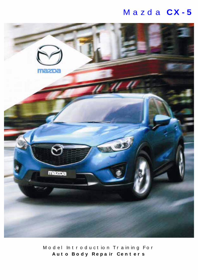
Model Introduction Training For Auto Body Repair Centers
Mazda CX-5
Copyright © 2012 Ford Motor Company of Southern Africa.
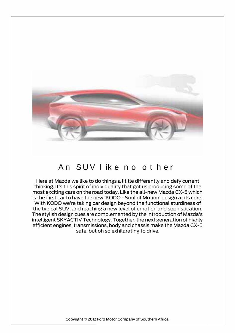
An SUV like no other
Here at Mazda we like to do things a lit tle differently and defy current thinking. It’s this spirit of individuality that got us producing some of the
most exciting cars on the road today. Like the all-new Mazda CX-5 which is the f irst car to have the new ‘KODO - Soul of Motion’ design at its core. With KODO we’re taking car design beyond the functional sturdiness of
the typical SUV, and reaching a new level of emotion and sophistication. The stylish design cues are complemented by the introduction of Mazda’s intelligent SKYACTIV Technology. Together, the next generation of highly efficient engines, transmissions, body and chassis make the Mazda CX-5
safe, but oh so exhilarating to drive.
Contents
Copyright © 2012 Ford Motor Company of Southern Africa.
Overview
Technical Specifications
Body
Restraint System
This introdution manual highlights the design and function of new vehicle models.
The introdution manual is not a repair manual!All values given are intended as a guideline only.
Some vehicle pictures may be overseas specification.
For body repair work, always refer to the current body repair manual on www.automx.co.za

Copyright © 2012 Ford Motor Company of Southern Africa.4
overview
Mazda CX-5 2.0L Active MT
• 6-speed manual transmission • 17" steel wheels• Tire pressure monitor• Hill launch assist• Radio/CD / AUX/ USB/ 4 speakers• Audio controls on steering wheel
Mazda CX-5 2.0L Dynamic AT
• 6-speed automatic transmission• 17" alloy wheels• Bluetooth• Multi-info display• Cruise control• Front fog lamps• Alarm• Karakuri tonneau cover• Leather covered gear knob and steering wheel• 6 speakers• 40:20:40 rear seat fold down
Mazda CX-5 2.0L Individual AT
• 6-speed automatic transmission • 19" alloy wheels • 9 speaker BOSE • Auto air conditioner • Adaptive Front Light System
(AFLS) • Auto headlamp levelling • Auto headlamp on/off • Auto interior rear view mirror
• Back-up monitor • Bi-Xenon headlamps • Heated Leather seats (driver & pass.) • Lumbar support - driver's seat • Parking sensors • Power seats • Rain sensing wipers • Running headlamp • Smart (hands-free) entry system • Sunroof

Copyright © 2012 Ford Motor Company of Southern Africa. 5
overview
Arctic White - A4D
Black - 16W
Velocity Red - 27A
Crystal White Pearl - 34K
Stormy Blue - 35J
Metropolitan Gray - 36C
Aluminum Metallic - 38P
Sky Blue - 41B
True Red - 41G
Colour Codes

Copyright © 2012 Ford Motor Company of Southern Africa.6
overview
Dimensions
A
D
B
C
E
A Length (mm) 4,555
B Width incl. mirrors (mm) 1,840
C Height (mm) 1,670
D Wheelbase (mm) 2,700
E Front track (mm) 1,585
E Rear track (mm) 1,590

Copyright © 2012 Ford Motor Company of Southern Africa. 7
overview
SKYACTIV G Petrol engine
The new SKYACTIV-G petrol engine features the compression ratio for a pro-duction engine of 13:1. With new 4-2-1 exhaust system, lightweight cavity pis-tons and numerous other innovative measures, it achieves highly competitive fuel economy and reduced CO2 emissions – and an equally impressiveincrease in torque across the entire rev range.
Benefits
• Combined fuel consumption of 6.8l for MT and 6.9l for AT according to Mazda’s testing conditions
• Power is at 114kW @ 6000rpm
• Torque is at 200Nm @ 4000 rpm
• CO2 emissions of 158g/km for MT and 161g/km for AT
SKYACTIV Transmissions
SKYACTIV-Drive
Supporting improved fuel economy, the six-speed SKYACTIV-Drive automatic transmission features a new lock-up clutch and provides linear acceleration with a smoother, more direct shift feel.
Benefits
• Smooth start-up and acceleration• Smooth, vibration-free gear shifting• Advanced design contributes to improved fuel
efficiency
SKYACTIV-MTSportier and precise, the six-speed SKYACTIV-MT manual transmission is compact and lightweight in design and generates less internal friction. This results in greater fuel economy and a shift feel reminiscent of a sports car.
Benefits
• Short, crisp and light gear shift• Direct sporty gear shift• Increased transmission efficiency improves fuel economy

Copyright © 2012 Ford Motor Company of Southern Africa.8
SKYACTIV-Chassis
• A next-generation high-performance lightweight chassis that balances precise handling with a comfortable ride feel to realize driving pleasure
• Newly developed front strut and rear multilink suspension ensures high rigidity and lightness.
• Mid-speed agility and high-speed stability — enhanced ride quality at all speeds achieved through a revision of the functional allocation of all the suspension and steering components
1. Combination of low-to mid-speed agility and high-speed stability2. Balance of ride comfort with low-to mid-speed agility3. Joint achievement of weight reduction and excellent tigidity
The front and rear suspension have been redesigned to deliver low-to mid-speed agility and high-speed stability, nimble yet high quality ride comfort, with a light chassis and superior rigidity. A lightweight, highly rigid cross mem-ber and electric power steering also contribute to quick handling.
TechnicAL
Trade-OffTrade-Off
Trade-Off
1. Combination of low-tomid-speed agility and
high-speed stability
2. Balance of ride comfortwith low-to mid-speed agility
3. Joint achievement of weightreduction and excellent rigidity
Feeling of onenesswith the vehicle
Stable& Safe Comfort
Weight reduction
Soft
Hard
Responsive
Unresponsive
Copyright © 2012 Ford Motor Company of Southern Africa. 9
TechnicAL
Combination of light feel at low-to-mid speeds and stability at high speeds
When the yaw gain (the force that turns a vehicle) is set at a high level to en-hance the car’s nimbleness at the low-to-mid speeds, it tends to become ex-cessive at high speeds, producing an oversensitive response in the car’s movements. To resolve this issue, we re-examined the geometry of the rear suspension. First of all, to ensure smooth movement at high speeds, we opti-mized the suspension links, and increased the grip of the rear wheels in re-sponse to impact (reducing the yaw gain).
Next, to ensure nimbleness of movement at low-to-mid speeds, we adopted a higher steering gear ratio (increasing yaw gain). By doing so, we simultane-ously increased yaw gain at low-mid speeds and reduced yaw gain at high speeds, achieving improved nimbleness at the low-mid speed range and greater stability at the high-speed range.
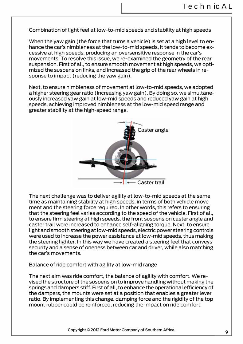
The next challenge was to deliver agility at low-to-mid speeds at the same time as maintaining stability at high speeds, in terms of both vehicle move-ment and the steering force required. In other words, this refers to ensuring that the steering feel varies according to the speed of the vehicle. First of all, to ensure firm steering at high speeds, the front suspension caster angle and caster trail were increased to enhance self-aligning torque. Next, to ensure light and smooth steering at low-mid speeds, electric power steering controls were used to increase the power assistance at low-mid speeds, thus making the steering lighter. In this way we have created a steering feel that conveys security and a sense of oneness between car and driver, while also matching the car’s movements.
Balance of ride comfort with agility at low-mid range
The next aim was ride comfort, the balance of agility with comfort. We re-vised the structure of the suspension to improve handling without making the springs and dampers stiff. First of all, to enhance the operational efficiency of the dampers, the mounts were set at a position that enables a greater lever ratio. By implementing this change, damping force and the rigidity of the top mount rubber could be reinforced, reducing the impact on ride comfort.
Caster angle
Caster trail

Copyright © 2012 Ford Motor Company of Southern Africa.10
The rear suspension trailing link attachment position was also shifted up-wards. In this way, the direction of movement of the trailing links is adjusted to more easily absorb longitudinal impact shocks from the road, contributing to improved ride comfort. At the same time, as this also prevents the rear of the vehicle from rising, the vehicle has increased stability when stopping, which helps to reduce stopping distance.
Lightweight cross member with high rigidity
To help to achieve the weight reduction target, we worked on the optimiza-tion of the cross member (suspension member) structure and engineering method. After first ensuring that the functionality requirements were met, CAE technology was then used to create a concept model to develop the op-timum structure. When doing so, we verified at the same time that this was coordinated with the overall vehicle package. In the front, the center car sec-tion was extended and the longitudinal offset of the lower arm attachment position was reduced. In the rear, the longitudinal span of the cross member was extended and the longitudinal offset of the lateral link attachment posi-tion was reduced. Welding flanges were also removed from the front and the rear, to enhance the coupling rigidity of the welded sections. The structure thus adopted achieves both weight reduction and superior rigidity, contribut-ing to weight reduction of the entire chassis, compared with current models.
TechnicAL
SKYACTIVNormalDirection of travel Direction of travel
30mm bump @ 30km/hr 30mm bump @ 30km/hr
Bush longitudinalimpact shock
Bush longitudinalimpact shock
Rear suspensiontrailing bush
Rear suspensiontrailing bush
Recession angle Recession angle
SKYACTIVSKYACTIV
Normal
Normal
Joining technologyStructural optimization
Enhanced coupling rigidity(removal of flanges)
Reduction oflongitudinal offsetbetween lower arm
support positionand center member
Expansion oflongitudinal
spanExpansionof centermember

Copyright © 2012 Ford Motor Company of Southern Africa. 11
Suspension
Front suspension
• Strut-type suspension adopted• For the front / rear crossmembers, the welded flange has been eliminated
(flange-less), the cross-section expanded and the connection rigidity of the welded parts improved to achieve both rigidity and light weight.
• By adoptiong a 6-point rigid mount-type front crossmember, the force generated from the tires is transmitted directly, and an agile vehicle response in low-to-mid speed range has been realized.
Rear suspension
• An E-type multi-link rear suspension adopted.• For the front /rear crossmembers, the welded flange has been eliminated
(flange-less), the cross-section expanded and the connection rigidity of the welded parts improved to achieve both rigidity and light weight.
TechnicAL
Coil spring
Front shock
Front stabilizer
absorber
control linkFront
stabilizer
Front lower arm
Frontcrossmember
Rear shockabsorber
Rear upperarm
Rear trailinglink
Rear laterallink
Rear crossmember
Rear stabilizer
Rear stabilizer control link
Coil spring
Rear lower arm

Copyright © 2012 Ford Motor Company of Southern Africa.12
SKYACTIV-Body
Highly rigid body and chassis that achieve outstanding crash safety perfor-mance through comprehensive weight reduction technology.
The SKYACTIV-Chassis is an impressive 14 per cent lighter, and features sus-pension and steering systems that have been redeveloped from scratch to re-inforce Mazda’s trademark driving dynamics while still achieving a lower overall weight, benefiting driving dynamics, economy and emissions.
The strut front and multi-link rear layout features lightweight construction as well optimised linkages and bushes for enhanced agility and greater ride comfort. A new electric power-steering set-up with a higher steering ratio, along with a new lightweight and highly rigid cross member results in excep-tional steering precision and feedback.
Mazda has always put the highest priority on offering driving pleasure, and istherefore strongly focused on weight. Reducing vehicle weight does not sim-ply boost fuel economy; combined with the innovative engines, it comple-ments the engine’s performance potential, and vastly improves the vehicles core performance attributes when driving, turning and stopping. To gain maximum benefit from the complete redesign of its base technologies, Maz-da also set itself the challenge of reducing the weight of its vehicles by ap-proximately 100 kilograms through a process of “comprehensive weight reduction,” which was focused mainly on the next generation body and chas-sis. This all-inclusive process aimed to achieve a lightweight and highly-rigid body with excellent crash safety performance by pursuing an ideal body structure, adopting new production technologies and substituting new mate-rials.
Body

Copyright © 2012 Ford Motor Company of Southern Africa. 13
A new-generation lightweight, highly-rigid body with outstanding crash safe-ty performance and high rigidity for greater driving pleasure
• High rigidity and lightness (8 percent lighter, 30 percent more rigid)• Outstanding crash safety performance and lightness• A "straight structure" in which each part of the frame is configured to be as
straight as possible. Additionally, a "continuous framework" approach was adopted in which each section functions in a coordinated manner with the other connecting sections
• Reduced weight through optimized bonding methods and expanded use of high-tensile steel
Ideal body structure
In terms of structure, we revisited the basic principles. For the basic frame-work, we adopted the concepts of ‘straightening’, and a ‘continuous frame-work’ in which each section functions in a coordinated manner with the other sections of the framework. The important thing when creating a light yet strong framework is to ensure that the structure disperses force widely throughout the entire framework, rather than receiving the force on only spe-cific sections of the vehicle.
Straight and continuous basic framework
For the underbody area, curves were removed as much as possible to create a straight frame in a continuous configuration from the front to the rear. For sections of the frame that still require some curvature, we implemented con-tinuous bonding with the horizontal frame to make the structure a closed section, thus contributing significantly to weight reduction while at the same time achieving rigidity.
SKYACTIV-BodyNormal Body
StraightCurvature
DiscontinuousContinuous
Straight ContinuousDeflections
Body

14
Body
The upperbody also functions as a constituent part of the continuously bond-ed framework. Specifically, the suspension mounting positions at the front and rear of the upperbody are directly bonded with the underbody framework as a “dual brace”.
In addition, by creating four ring structures for the upperbody that includes the roof rail and B-pillar, and the entire reinforcement area of the underbody, the overall rigidity of the body has been further enhanced.
Multi-load path structure
To improve crash safety performance, we adopted a multi-load path struc-ture. The structure efficiently absorbs the load at the time of a crash by dis-persing it in multiple directions. For example, energy received when a frontal collision occurs is absorbed by being dispersed along three continuous routes (paths): from the front frame to the B-frame, from the front frame to the side
Joins frameworkdirectly to underbody
B-pillar and underbodyconnected via closed section
Rear damper mountsconnected via closed section
Front suspension mounts &rear suspension crossconnected via closed section
Upperbody and underbodyconnected via ring structure
Copyright © 2012 Ford Motor Company of Southern Africa.

Body
Copyright © 2012 Ford Motor Company of Southern Africa.
of the body, and from the front frame to the A-pillar. In particular, the upper branch frame, which diverts the load to the A-pillar, is a multi-functional part that also works to cancel the upward motion of the front frame. To create this kind of path, parts such as door hinges, which do not normally play a role in absorbing shock, are important elements in the design. Naturally, the multi-load path structure is adopted for lateral collisions and rear collisions as well to function in the same way, thus greatly improving safety performance.
The multi-load path approach was also adopted for individual parts. We focused on directing the crash energy mainly along the ridge lines of the parts, mold-ing the front tip of the front frame into a cross shape. In a conventional square section, there are four ridge lines, but when a cross is created there are twelve ridge lines, and the shock is dispersed more widely. By doing so, the energy is then absorbed more efficiently, the space in the engine room is more effec-tively used, and there is also greater freedom in exterior design.
Optimized engineering process
To create a circular structure for the reinforcement, weld bonding was used for the roof rail section. Previously, this structure was separated from the rear frame due to the body assembly process. To bond this section directly, we adopted a method whereby the parts are bonded together in advance using the weld bonding method and then sent on to the assembly process as a bonded unit. By adopting this method, we have achieved continuous bond-ing, at the same time greatly increasing the number of spot weld points, which contribute to the excellent body rigidity.
15

Copyright © 2012 Ford Motor Company of Southern Africa.16
Body structure
In terms of materials, we have greatly increased our use of high-tensile steel, which is lightweight and has excellent strength and rigidity. In the new body , high-tensile steel, is used for most of the main parts, and this has resulted in significant weight reduction benefits.
Body
Weld bonded sections
Increased spot weld points

Copyright © 2012 Ford Motor Company of Southern Africa. 17
No Part Name MPa No Part Name MPa
1 Bumper bracket 590 18 Lower cowl side reinforcement (rear) 590
2 Front side frame (outer, rear) 590 19 Roof reinforcement No.2 590
3 Front side frame (inner, rear) 590 20 Front B frame front 590
4 Apron reinforcement No.3 590 21 Front B frame rear 590
5 Front frame (rear) 590 22 Floor reinforcement 780
6 Inner front pillar 780 23 Crossmember No.2 590
7 Inner hinge pillar 590 24 Crossmember No.2.5 780
8 Roof rail (inner) 590 25 Tunnel reinforcement 590
9 Roof rail reinforcement 780 26 Side sill (inner, front) 590
10 Front pillar reinforcement 590 27 Side sill (inner, rear) 780
11 Hinge reinforcement (upper) 590 28 Crossmember No.3 (lower) 590
12 Hinge reinforcement lower 590 29 Rear frame reinforcement 590
13 Side sill reinforcement 780 30 Rear side frame (front) 590
14 Center pillar reinforcement (upper) 980 31 Rear side frame (center) 590
15 Center pillar reinforcement (lower) 590 32 Rear side frame (rear) 590
16 Side sill reinforcement (rear) 590 33 Floor side panel No.1 590
17 Suspension housing reinforcement (upper) 780 34 Rear bumper bracket 590
Body
Ultra high-tension steel

Copyright © 2012 Ford Motor Company of Southern Africa.18
Characteristics of Ultra High-Tensile Steel Plates• Ultra high-tensile steel plates have enhanced tensile strength compared to
previous high-tensile steel plates.• Because the strength is maintained even though the plates are thin-
walled, the ultra high-tensile steel plates are used for the frames and the main frame parts which form the cabin, reducing the weight of the vehicle.
• Enhanced shock absorption has improved the safety.Range of Use and Cautions for Service• Because the ultra high-tensile steel is hard and it may be difficult to
reform, when extracting the damaged part using a frame repair machine, perform the work verifying that other parts are not affected.
• When drilling welded parts, use a well-ground drill bit.• After welding, inspect the weld strength. If adhesion is poor, perform arc
welding (plug welding).
Body panel
Outline• The multi-load path and triple H-shaped structure of distributing the
power absorbed at the collision were used for the body shell.• A ring structure has been adopted for the triple H structure, realizing top-
level crash safety performance.• Crushable structure from which an engine mounting bracket and suspen-
sion crossmember are made to secede at the collision is used for the body frame of an engine room.
• The energy absorption space between a bonnet and engine was secured.
Construction
Body
Side Collision

Copyright © 2012 Ford Motor Company of Southern Africa. 19
Triple H-shaped structure
• An H-shaped structure has been adopted in which reinforcements are equipped in the floor, side frame, and roof, and each connection area is strengthened.
• The combination of these three structural areas provide the strong triple H-shaped structure.
• Triple H structure distributes the impulse force at the side collision to rein-forcement of the roof, cabin side frame, and floor.
• Triple H-shaped structure controls the twisting of the cabin while driving.
Crushable structure
• Engine mounting brackets and front suspension crossmember are made to break away during a collision.
Multi-load path
• The multi-load path is stabilized during a collision, and has set the load distribution load path which carries out energy absorption.
Body
Engine mounting bracket
Engine mounting bracket Front suspension crossmember

Copyright © 2012 Ford Motor Company of Southern Africa.20
The front side frame, front B frame and rear side frame are made into straight forms.
The front side frame is supported by the side sill, front B frame and side mem-ber.
Bonnet
Purpose, Function
• The bonnet is constructed with a large space between the front end of the bonnet and the engine to absorb an impact.
Body
Rear side frame
Front B frame
Front side frame
Front B frame
Front side frame
Forward collisionSide
Member

Copyright © 2012 Ford Motor Company of Southern Africa. 21
Construction
• The bonnet stiffener positioned at the front end of the bonnet is shaped so that it collapses easily during an impact. In addition, there is an impact absorbing space which facilitates impact absorption.
• The large space between the bonnet and the engine facilitates impact absorption.
Bonnet
Engine
Bonnet stiffener
Bonnet stiffener Bonnet
Engine
Impact absorbingspace
Impact absorbingspace
Body

Copyright © 2012 Ford Motor Company of Southern Africa.22
Airbag system service warnings
Airbag module inspection
• Inspecting an airbag module using a tester can operate (deploy) the airbag module, which may cause serious injury. Do not use a tester to inspect an airbag module. Always use the onboard diagnostic function to diagnose the airbag module for malfunctions.
Airbag module handling
• Handling a live (undeployed) airbag module that is pointed toward your body could result in serious injury if the airbag module were to accidentally operate (deploy). When carrying a live (undeployed) airbag module, point the deployment surface away from your body to lessen the chance of injury in case it operates (deploys).
Restraint System

Copyright © 2012 Ford Motor Company of Southern Africa. 23
• A live (undeployed) airbag module placed with its deployment surface to ground is dangerous. If the airbag module were to accidentally operate (deploy), it could cause serious injury. Always place a live (undeployed) airbag module with its deployment surface up.
Side Air Bag Module Handling
• When a side air bag module operates (deploys) due to a collision, the inte-rior of the seat back (pad, frame, trim) may become damaged. If a side air bag does not operate (deploy) normally from a seat back that has been reused, a serious accident may result. After a side air bag has operated (deployed), always replace both the side air bag module and the seat back (pad, frame, trim) with new parts. After servicing, verify that the seat oper-ates normally and that the wiring harness is not caught.
SAS Control Module Handling
• When connecting or disconnecting the SAS control module connector, a person charged with static electricity could accidentally operate (deploy) each air bag module. Before connecting or disconnecting the SAS control module connector, discharge any charged static electricity from your body.
• Removing the SAS control module or disconnecting the SAS control mod-ule connector with the ignition ON can activate the sensor in the SAS con-trol module and operate (deploy) the air bags and pre-tensioner seat belts, which may cause serious injury. Before removing the SAS control module or disconnecting the SAS control module connector, always switch the ignition to off, disconnect the negative battery cable, and then wait for 1 min or more to allow the backup power supply of the SAS control module to deplete its stored power.
• Connecting the SAS control module connector with the SAS control mod-ule not securely fixed to the vehicle is dangerous. The sensor in the SAS control module could send an electrical signal to the air bag modules and pre-tensioner seat belts. This will operate (deploy) the air bags and pre-tensioner seat belts, which may result in serious injury. Therefore, before connecting the connector, securely fix the SAS control module to the vehi-cle.
Restraint System

Copyright © 2012 Ford Motor Company of Southern Africa.24
• Because a sensor is built into the SAS control module, once the air bags and pre-tensioner seat belts have operated (deployed) due to a collision or other causes, the SAS control module must be replaced with a new one even if the used one does not have any visible external damage or defor-mation. The used SAS control module may have been damaged internally, which may cause improper operation. If the SAS control module is reused, the air bags and pre-tensioner seat belts may not operate (deploy) nor-mally, which could result in a serious accident. Always replace the SAS control module with a new one. The SAS control module cannot be bench-checked or self-checked.
Crash Zone Sensor Handling
• Removing the crash zone sensor or disconnecting the crash zone sensor connector with the ignition ON can activate the crash zone sensor and operate (deploy) the air bags and pre-tensioner seat belts, which may cause serious injury. Before removing the crash zone sensor or disconnect-ing the crash zone sensor connector, always switch the ignition to off, dis-connect the negative battery cable, and then wait for 1 min or more to allow the backup power supply of the SAS control module to deplete its stored power.
• If the crash zone sensor is subjected to shock or the sensor is disassem-bled, the air bags and pretensioner seat belts may accidentally operate (deploy) and cause injury, or the system may fail to operate normally and cause a serious accident. Do not subject the crash zone sensor to shock or disassemble the sensor.
• Because a sensor is built into the crash zone sensor, once the air bags and pre-tensioner seat belts have operated (deployed) due to a collision or other causes, the crash zone sensor must be replaced with a new one even if the used one does not have any visible external damage or deformation. If the crash zone sensor is reused, the air bags and pre-tensioner seat belts may not operate (deploy) normally, which could result in a serious acci-dent. Always replace the crash zone sensor with a new one. The crash zone sensor cannot be bench-checked or self-checked.
Side Air Bag Sensor Handling
• Removing the side air bag sensor or disconnecting the side air bag sensor connector with the ignition ON can activate the side air bag sensor and operate (deploy) the side air bag, which may cause serious injury. Before removing the side air bag sensor or disconnecting the side air bag sensor connector, always switch the ignition to off, disconnect the negative bat-tery cable, and then wait for 1 min or more to allow the backup power sup-ply of the SAS control module to deplete its stored power.
• If the side air bag sensor is subjected to shock or the sensor is disassem-bled, the side air bag may accidentally operate (deploy) and cause injury, or the system may fail to operate normally and cause a serious accident. Do not subject the side air bag sensor to shock or disassemble the sensor.
Restraint System

Copyright © 2012 Ford Motor Company of Southern Africa. 25
• Because a sensor is built into the side air bag sensor, once the air bag has operated (deployed) due to a collision or other causes, the side air bag sensor must be replaced with a new one even if the used one does not have any visible external damage or deformation. If the side air bag sensor is reused, the side air bag may not operate (deploy) normally, which could result in a serious accident. Always replace the side air bag sensor with a new one. The side air bag sensor cannot be bench-checked or self-checked.
Pre-tensioner Seat Belt Inspection
• Inspecting a pre-tensioner seat belt using a tester can operate (deploy) the pre-tensioner seat belt, which may cause serious injury. Do not use a tester to inspect a pre-tensioner seat belt. Always use the on-board diag-nostic function to diagnose the pre-tensioner seat belt for malfunctions.
Air bag system service cautions
Air Bag System Component Disassembly
• Disassembling the air bag system components could cause it to not oper-ate (deploy) normally. Never disassemble any air bag system components.
Air Bag Module, Pre-tensioner Seat Belt Handling
• Oil, grease, or water on the air bag modules may cause the air bags to fail to operate (deploy) in an accident. Never allow oil, grease, or water to get on the air bag modules.
• Inserting a screwdriver or similar object into the connector of an air bag module or pretensioner seat belt may damage the connector and cause the air bag module or pre-tensioner seat belt to operate (deploy) improp-erly, which may cause serious injury. Never insert any foreign objects into the air bag module or pretensioner seat belts.
Restraint System

Copyright © 2012 Ford Motor Company of Southern Africa.26
Air Bag Module, Pre-tensioner Seat Belt Reuse
• Even if an air bag module or a pre-tensioner seat belt does not operate (deploy) in a collision and does not have any external signs of damage, it may have been damaged internally, which may cause improper operation. Before reusing a live (undeployed) air bag module and the pre-tensioner seat belts, always use the on-board diagnostic to diagnose the air bag module and the pre-tensioner seat belts to verify that they have no mal-function.
Air Bag Wiring Harness Repair
• Incorrectly repairing an air bag wiring harness can accidentally operate (deploy) the air bag module and pre-tensioner seat belts. If a problem is found in the air bag wiring harness, always replace the wiring harness with a new one.
Restraint System

Copyright © 2012 Ford Motor Company of Southern Africa. 27
Air bag component location
Restraint System
Instument cluster
Air bag systemwarning light
Clock springDriver side airbag module
Curtain airbag module
*Passenger air bagdeactivation (PAD) indicator
Passenger air bag module
*Passenger air bagdeactivation (PAD) switch
SAS control module
Passengerair bag
ON OFF
Passenger seatDriver seat
Side air bagmodule
Pre-tensionseat belt
Side air bagsensor No. 2
Side air bagsensor No. 1Crash zone sensors
* : Fitted with PAD switch
SAS Control module
Purpose
• The SAS control module controls the air bag system operation.
Function
• During a frontal collision, the SAS control module controls the following air bag module operation (deployment).
— Driver-side air bag module— Passenger-side air bag module— Driver/passenger-side pre-tensioner seat belt
• During a lateral collision, the SAS control module controls the following air bag module operation (deployment).
— Side air bag module on the collision side— Curtain air bag module on the collision side— Driver/passenger-side pre-tensioner seat belt

Copyright © 2012 Ford Motor Company of Southern Africa.28
• If an air bag is deployed due to a vehicle collision, the SAS control module sends an air bag deployment signal to each control module.
• When the signal is received, each control module performs the following controls to reduce secondary injuries caused by the vehicle collision.
— Rear body control module (RBCM): Collision detection unlock function.— DSC HU/CM, front body control module (FBCM): Secondary collision re duction (SCR)
Backup power supply function
• The backup power supply function enables the condenser to discharge and supply power to assure air bag system operation/deployment properly for a specified time even if the power supply to the SAS control module is cut due to a collision.
Configuration function
• Identifies the variation of the air bag module installed to the vehicle when replacing the SAS control module with a new one.
• If the air bag module installed to the vehicle and the module identified by the SAS control module differ, a DTC is displayed.
• Refer to the Workshop Manual for the configuration setting procedure.
Yaw Rate Sensor
• The yaw rate sensor in the SAS control module detects the vehicle yaw rate (vehicle turning angle speed), and sends the detected rate to the DSC HU/CM via special CAN lines between the SAS control module and the DSC CM.
Low-G sensor
• The low-G sensor in the SAS control module detects the vehicle longitudi-nal accelerations, and sends the detected accelerations to the DSC HU/CM via special CAN lines between the SAS control module and the DSC CM.
Construction
• SAS control module installed under the rear console.• The following sensors are built into the SAS control module.— Crash sensor— Yaw rate sensor— Low-G sensor
• If the degree of impact detected by the crash zone sensor and the crash sensor built into the SAS control module exceeds the set value during a frontal collision to the vehicle, the SAS control module sends an operation (deployment) signal to the air bag module and the pre-tensioner seat belts.
Restraint System

Copyright © 2012 Ford Motor Company of Southern Africa. 29
• If the degree of impact detected by side air bag sensor No. 1 or No. 2 and the crash sensor built into the SAS control module exceeds the set value during a side collision to the vehicle, the SAS control module sends an operation (deployment) signal to the side air bag module and curtain air bag module.
SAS control module removal/installation
Warning
• Handling the SAS control module or air bag module improperly can acci-dentally deploy the air bag modules and pre-tensioner seat belt, which may seriously injure you. Read the air bag system service warnings and cautions before handling the air bag module.
• If the connector is connected and the ignition switch is turned to the ON position with the SAS control module not secured completely using the installation nuts, the SAS control module may detect a degree of impact even when something contacts it lightly, deploying the air bag module and pre-tensioner seat belt accidentally.
• If the DSC sensor initialization procedure is not completed, it could result in an unexpected accident due to the DSC being inoperative. Therefore, after the SAS control module is replaced, always perform the DSC sensor initial-ization procedure to ensure proper DSC operation.
• If configuration is not performed when the SAS control module is replaced with a new one, the vehicle specification information is not stored in the SAS control module and the system will not operate normally.
Secondary collision reduction (SCR)
Purpose
• The Secondary Collision Reduction (SCR) is a part of the DSC system functions which operates the automatic brakes and flashes the hazard warning lights when the vehicle is hit while it is stopped and moved by the impact to avoid the occurrence of a secondary collision.
Warning
• The secondary collision reduction (SCR) performs the brake control (SCR brake), however, it is not a system which guarantees collision prevention under all conditions. Because deceleration by the brake control (SCR brake) is limited.
Note
• The secondary collision reduction (SCR) is a system for assisting driver operations. Accordingly, if the conditions for the secondary collision reduc-tion (SCR) are met, or even when the secondary collision reduction (SCR) is operating, if the driver operates the steering wheel, accelerator pedal, and the brake pedal, the driver’s operations take precedence and the sec-ondary collision reduction (SCR) operation is canceled.
Restraint System

Copyright © 2012 Ford Motor Company of Southern Africa.30
Function
• The secondary collision reduction (SCR) functions are categorized as fol-lows:
— Hazard warning (SCR hazard) which flashes the hazard warning lights to warn surrounding vehicles when the vehicle is collision.1. The hazard warning (SCR hazard) is equipped as standard.— Brake control (SCR brake) which operates the automatic brakes when the vehicle is hit while it is stopped and moved by the impact.2. The brake control (SCR brake) is equipped along with smart city brake
support (SCBS).
Clock spring
Caution• If the disc on the combination switch is deformed or has foreign material
adhering to it, performance of the steering angle sensor may be reduced, causing abnormal operation. When handling the clock spring, be careful not to deform the disc and make sure there is no foreign material on it.
Clock Spring Installation Note
Caution• If the clock spring is not adjusted, the spring wire in the clock spring will
break due to overtension when the steering wheel is turned. Always adjust the clock spring after installing it.
• Adjust the clock spring after installing it.
Clock spring adjustment
1. Set the front wheels straight ahead.
Caution• The clock spring will break if over-wound. Do not forcibly turn the clock
spring.
2. Turn the clock spring clockwise until it stops.
3. Turn the clock spring counter-clockwise approx. 2 turns.
4. Align the mark on the clock spring with the mark on the outer hous-ing.
Note• After adjusting the alignment
marks, the guides can be verified in the viewing slots shown in the figure.
Restraint System
Guide
Alignmentmarks
Clock spring
Alignmentmarks
Clock spring
Viewingslot


![KAA IPI kurz Karakuri Akademie 2020 Akademie_IPI_2020.pdf · 7HUPtQRYê NDOHQGi 0RGXO 7pPDWD 5R]VDK 7HUPtQ 0HFKDQLFNp NDUDNXUL VWUXNWXU\ 3RGVWDWDNDUNXUL =iNODG\ PHFKDQLN\ NLQHPDWLN\](https://img.pdfslide.net/doc/110x75/6042c1bd5912f748a514b40f/kaa-ipi-kurz-karakuri-akademie-akademieipi2020pdf-7huptqry-ndohqgi-0rgxo.jpg)