Embed Size (px)
Citation preview

OPERATION MANUAL
THIS MANUAL MUST ACCOMPANY THE EQUIPMENT AT ALL TIMES.
MODEL J36E2WALK-BEHIND TROWEL
(2 HP 230 VAC ELECTRIC MOTOR)
S/N LE0118040 AND ABOVE
Revision #5 (09/02/20)
PN: 30573
To find the latest revision of this publication or associated parts manual, visit our website at:
www.multiquip.com

PAGE 2 — J36E2 ELECTRIC WALK-BEHIND TROWEL • OPERATION MANUAL — REV. #5 (09/02/20)
Grinding/cutting/drilling of masonry, concrete, metal andother materials with silica in their composition may giveoff dust or mists containing crystalline silica. Silica is abasic component of sand, quartz, brick clay, granite andnumerous other minerals and rocks. Repeated and/orsubstantial inhalation of airborne crystalline silica cancause serious or fatal respiratory diseases, includingsilicosis. In addition, California and some otherauthorities have listed respirable crystalline silica as asubstance known to cause cancer. When cutting suchmaterials, always follow the respiratory precautionsmentioned above.
WARNING
Grinding/cutting/drilling of masonry, concrete, metal andother materials can generate dust, mists and fumescontaining chemicals known to cause serious or fatalinjury or illness, such as respiratory disease, cancer,birth defects or other reproductive harm. If you areunfamiliar with the risks associated with the particularprocess and/or material being cut or the composition ofthe tool being used, review the material safety datasheet and/or consult your employer, the materialmanufacturer/supplier, governmental agencies such asOSHA and NIOSH and other sources on hazardousmaterials. California and some other authorities, forinstance, have published lists of substances known tocause cancer, reproductive toxicity, or other harmfuleffects.
Control dust, mist and fumes at the source wherepossible. In this regard use good work practices andfollow the recommendations of the manufacturers orsuppliers, OSHA/NIOSH, and occupational and tradeassociations. Water should be used for dustsuppression when wet cutting is feasible. When thehazards from inhalation of dust, mists and fumes cannotbe eliminated, the operator and any bystanders shouldalways wear a respirator approved by NIOSH/MSHA forthe materials being used.
WARNING
SILICOSIS WARNING RESPIRATORY HAZARDS
SILICOSIS/RESPIRATORY WARNINGS

J36E2 ELECTRIC WALK-BEHIND TROWEL • OPERATION MANUAL — REV. #5 (09/02/20) — PAGE 3
TABLE OF CONTENTS
J36E2 Electric Walk-Behind TrowelSilicosis/Respiratory Warnings ................................ 2Table of Contents ..................................................... 3Training Checklist .................................................... 4Daily Pre-Operation Checklist ................................. 5Safety Information ............................................. 6–10Specifications ........................................................ 11General Information ............................................... 12Components .......................................................... 13Electric Motor ........................................................ 14Setup ..................................................................... 15Inspection .............................................................. 16Operation ......................................................... 17–19Options .................................................................. 20Maintenance .................................................... 21–28Troubleshooting ..................................................... 29Electrical Wiring Diagram ...................................... 30

PAGE 4 — J36E2 ELECTRIC WALK-BEHIND TROWEL • OPERATION MANUAL — REV. #5 (09/02/20)
TRAINING CHECKLIST
Training Checklist
No. Description OK? Date
1 Read operation manual completely.
2Machine layout, location of
components, checking of gearbox oil level.
3 Operation of controls (machine not running).
4 Safety controls, safety stop switch operation.
5 Emergency stop procedures.
6 Startup of machine, applying power.
7 Maintaining a hover.
8 Maneuvering.
9 Pitching.
10 Concrete fi nishing techniques.
11 Shutdown of machine.
12 Lifting of machine.
13 Machine transport and storage.

J36E2 ELECTRIC WALK-BEHIND TROWEL • OPERATION MANUAL — REV. #5 (09/02/20) — PAGE 5
DAILY PRE-OPERATION CHECKLIST
Daily Pre-Operation Checklist
1 Gearbox oil level
2 Condition of blades
3 Blade pitch operation
4 Safety stop switch operation
5 Main ON/OFF switch operation

PAGE 6 — J36E2 ELECTRIC WALK-BEHIND TROWEL • OPERATION MANUAL — REV. #5 (09/02/20)
SAFETY INFORMATION
DO NOT operate or service the equipment before reading the entire manual. Safety precautions should be followed at all times when operating this equipment. Failure to read and understand the safety messages and operating instructions could result in injury to yourself and others.
SAFETY MESSAGES
The four safety messages shown below will inform you about potential hazards that could injure you or others. The safety messages specifi cally address the level of exposure to the operator and are preceded by one of four words: DANGER, WARNING, CAUTION or NOTICE.
SAFETY SYMBOLS
DANGER
Indicates a hazardous situation which, if not avoided, WILL result in DEATH or SERIOUS INJURY.
WARNING
Indicates a hazardous situation which, if not avoided, COULD result in DEATH or SERIOUS INJURY.
CAUTION
Indicates a hazardous situation which, if not avoided, COULD result in MINOR or MODERATE INJURY.
NOTICE
Addresses practices not related to personal injury.
Potential hazards associated with the operation of this equipment will be referenced with hazard symbols which may appear throughout this manual in conjunction with safety messages.
Electric shock hazards
Explosive area hazards
Rotating parts hazards
Symbol Safety Hazard
Crush hazards
Respiratory hazards

J36E2 ELECTRIC WALK-BEHIND TROWEL • OPERATION MANUAL — REV. #5 (09/02/20) — PAGE 7
SAFETY INFORMATION
SAFETY DECALS
Decals associated with the safe operation of this equipment are defi ned below.
To avoid injury you must readand understand operator’s manual before using this machine.
WARNINGRead Manual
WARNINGBelt Guard Hazard
DECAL DEFINITIONWARNING
Rotating Blade HazardKeep hands, fingers, and feet clearof engine fan blades and guard rings.
Keep hands and fingers clear fromengine belts. Moving parts can crush. DO NOT remove belt guards.
P/N 23700
NEVER allow any person to stand underneath the trowel while lifting.
DANGERLifting/Crush Hazard
This machine to be operated by qualified personnel only. Ask for training as needed.
WARNINGTraining
Moving parts can cut.DO NOT remove guards.Stop engine before servicing.
DO NOT lift trowel with pans attached.ALWAYS make sure handleis securely attached.On Quick PitchTM models make sureT-Handle latch is locked (engaged).
DECAL DEFINITION
Visually inspect designated locationsbefore operating trowel. Check thatall components are in appropriateoperating condition.
NOTICEVisual Inspection
This is the symbol for a belt drive.
NOTICEBelt Drive
P/N 36099 ALWAYS wear appropriate clothing before operating trowel.
NOTICEProtective Clothing

PAGE 8 — J36E2 ELECTRIC WALK-BEHIND TROWEL • OPERATION MANUAL — REV. #5 (09/02/20)
SAFETY INFORMATION
GENERAL SAFETY
CAUTION
�NEVER operate this equipment without proper protective clothing, shatterproof glasses, respiratory protection, hearing protection, steel-toed boots and other protective devices required by the job or city and state regulations.
�Avoid wearing jewelry or loose-fi tting clothes that may snag on the controls or moving parts as this can cause serious injury.
�NEVER operate this equipment when not feeling well due to fatigue, illness or when on medication.
�NEVER operate this equipment under the infl uence of drugs or alcohol.
�ALWAYS clear the work area of any debris, tools, etc. that would constitute a hazard while the equipment is in operation.
�No one other than the operator is to be in the working area when the equipment is in operation.
�DO NOT use the equipment for any purpose other than its intended purposes or applications.
NOTICE
� This equipment should only be operated by trained and qualifi ed personnel 18 years of age and older.
�Whenever necessary, replace nameplate, operation and safety decals when they become diffi cult to read.
�Manufacturer does not assume responsibility for any accident due to equipment modifi cations. Unauthorized equipment modifi cation will void all warranties.
�NEVER use accessories or attachments that are not recommended by Multiquip for this equipment. Damage to the equipment and/or injury to the user may result.
�ALWAYS know the location of the nearest fi re extinguisher.
�ALWAYS know the location of the nearest fi rst aid kit.
�ALWAYS know the location of the nearest phone or keep a phone on the job site. Also, know the phone numbers of the nearest ambulance, doctor and fi re department. This information will be invaluable in the case of an emergency.

J36E2 ELECTRIC WALK-BEHIND TROWEL • OPERATION MANUAL — REV. #5 (09/02/20) — PAGE 9
SAFETY INFORMATION
TROWEL SAFETY
DANGER
�NEVER operate the equipment in an explosive atmosphere or near combustible materials. An explosion or fi re could result causing severe bodily harm or even death.
WARNING
�ALWAYS keep clear of rotating or moving parts while operating the trowel.
�DO NOT start or operate the trowel if the drive train will not disengage. Centrifugal force between the trowel and surface when starting can cause uncontrolled handle movement that can cause serious injury. The handle must not move while starting the electric motor.
�NEVER disconnect any emergency or safety devices. These devices are intended for operator safety. Disconnection of these devices can cause severe injury, bodily harm or even death. Disconnection of any of these devices will void all warranties.
CAUTION
�NEVER stand on the trowel during operation.
�NEVER lubricate components or attempt service on a running machine.
�NEVER place your feet or hands inside the guard rings while starting or operating this equipment.
NOTICE
�ALWAYS keep the machine in proper running condition.
� Fix damage to the machine and replace any broken parts immediately.
�ALWAYS store equipment properly when it is not being used. Equipment should be stored in a clean, dry location out of the reach of children and unauthorized personnel.
�A safety manual for operating and maintenance personnel of concrete power trowels produced by the Association of Equipment Manufacturers (AEM) can be obtained for a fee by ordering through their website at www.aem.org. Order FORM PT-160
ELECTRIC MOTOR SAFETY
WARNING
�NEVER operate the electric motor with guards removed.
�Keep fi ngers, hands, hair and clothing away from all moving parts to prevent injury.
GENERATOR SAFETY
If using a generator to power the trowel, refer to the applicable generator manual safety information section.
ELECTRICAL SAFETY
DANGER
�NEVER let power cords or cables lay in water.
�NEVER use damaged or worn cables or cords when connecting equipment to a generator or power source. Inspect for cuts in the insulation.
�NEVER grab or touch a live power cord or cable with wet hands. The possibility exists of electrical shock, electrocution or death.
�Make sure power cables are securely connected. Incorrect connections may cause electrical shock and damage to the trowel.

PAGE 10 — J36E2 ELECTRIC WALK-BEHIND TROWEL • OPERATION MANUAL — REV. #5 (09/02/20)
SAFETY INFORMATION
TRANSPORTING SAFETY
CAUTION
�NEVER allow any person or animal to stand underneath the equipment while it is being lifted.
NOTICE
�Some walk-behind trowels can be lifted or moved by two people utilizing lifting tubes or other special attachments. Generally, however, they must be lifted using lifting bails and cranes, hoists, or forklifts.
�NEVER transport the trowel with fl oat pans attached unless safety catches are used and are specifi cally cleared for such transport by the manufacturer.
�NEVER hoist the trowel more than three feet off the ground with fl oat pans attached.
�Before lifting, make sure that the lifting bail is not damaged.
�ALWAYS make sure the crane or lifting device has been properly secured to the lifting bails of the equipment.
�ALWAYS shut down the electric motor before transporting.
�NEVER lift the equipment while the motor is running.
�Use adequate lifting cable (strap or rope) of suffi cient strength.
�DO NOT lift the machine to unnecessary heights.
�ALWAYS tie down the equipment during transport by securing the equipment.
ENVIRONMENTAL SAFETY/DECOMMISSIONING
NOTICE
Decommissioning is a controlled process used to safely retire a piece of equipment that is no longer serviceable. If the equipment poses an unacceptable and unrepairable safety risk due to wear or damage or is no longer cost effective to maintain (beyond life-cycle reliability) and is to be decommissioned (demolition and dismantlement), be sure to follow the rules below.
�Contact your country’s Department of Public Works or recycling agency in your area and arrange for proper disposal of any electrical components, waste or oil associated with this equipment.
�When the life cycle of this equipment is over, it is recommended that the trowel frame and all other metal parts be sent to a recycling center.
Metal recycling involves the collection of metal from discarded products and its transformation into raw materials to use in manufacturing new products.
Recyclers and manufacturers alike promote the process of recycling metal. Using a metal recycling center promotes energy cost savings.
J36E2 ELECTRIC WALK-BEHIND TROWEL • OPERATION MANUAL — REV. #5 (09/02/20) — PAGE 11
SPECIFICATIONS
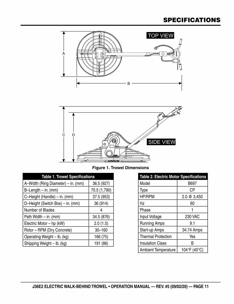
Figure 1. Trowel Dimensions
C
SIDE VIEW
A
B
TOP VIEW
C CD
Table 1. Trowel SpecificationsA–Width (Ring Diameter) – in. (mm) 36.5 (927)
B–Length – in. (mm) 70.5 (1,790)
C–Height (Handle) – in. (mm) 37.5 (953)
D–Height (Switch Box) – in. (mm) 36 (914)
Number of Blades 4
Path Width – in. (mm) 34.5 (876)
Electric Motor – hp (kW) 2.0 (1.5)
Rotor – RPM (Dry Concrete) 30–160
Operating Weight – lb. (kg) 166 (75)
Shipping Weight – lb. (kg) 191 (86)
Table 2. Electric Motor SpecificationsModel B697Type CPHP/RPM 2.0 @ 3,450Hz 60Phase 1Input Voltage 230 VACRunning Amps 9.1Start-up Amps 34.74 AmpsThermal Protection YesInsulation Class BAmbient Temperature 104°F (40°C)

PAGE 12 — J36E2 ELECTRIC WALK-BEHIND TROWEL • OPERATION MANUAL — REV. #5 (09/02/20)
GENERAL INFORMATION
INTENDED USE
Operate this trowel, tools and components in accordance with the manufacturer’s instructions. Use of any other tools for stated operation is considered contrary to designated use. The risk of such use lies entirely with the user. The manufacturer cannot be held liable for damages as a result of misuse.
TROWEL FAMILIARIZATION
This walk-behind trowel is designed for the floating and finishing of concrete slabs.
Walk around the trowel and take notice of all of the major components (Figure 2)—the electric motor, blades, steering handle, operator presence switch, gearbox, etc.
Read all safety instructions carefully. Safety instructions will be found throughout this manual and on the trowel. Keep all safety information in good, readable condition. Operators should be well trained on the operation and maintenance of the trowel.
Before using your trowel, test it on a flat, watered-down section of finished concrete that is free of any debris or other objects.
This trial test run will increase your confidence in using the trowel and will familiarize you with the trowel’s controls. In addition you will understand how the trowel handles under actual conditions.
ELECTRIC MOTOR
This trowel is equipped with a 2 hp, 230 VAC, 60 Hz, single-phase motor. Refer to the wiring chart affixed to the electric motor casing for the desired voltage configuration.
DRIVE SYSTEM
Power is transferred from the electric motor to the gearbox input shaft via a V-belt pulley drive system. The pulley engages using a centrifugal clutch. See the parts section of this manual for a breakdown of the drive system.
GEARBOX
The gearbox is located beneath the motor and transfers power to the spider assembly. The gearbox controls the rotational speed of the trowel and is equipped with two shafts (input and output).
SPIDER
The vertical output shaft of the gearbox connects to a cast hub called the spider. The spider has four arms that extend outward to which blades or other accessories are attached. Remember that as the gearbox output shaft rotates, so does the spider assembly.
GUARD RING
This unit is equipped with a safety guard ring. It is designed to prevent objects from coming into contact with the rotating blades while the trowel is in operation.
BLADES
The blades of the trowel finish the concrete as they are rotated around the surface. The trowel comes equipped with four combination blades (8 in./203 mm wide) per rotor equally spaced in a radial pattern and attached to the vertical rotating shaft by means of the spider assembly.
OPERATOR PRESENCE SWITCH
In the event of a trowel runaway condition (the operator releases the handlebar during operation), the operator presence switch will stop the electric motor and bring the trowel to a halt.
TRAINING
For proper training, please use the Training Checklist form located in the front of this manual. This checklist will provide an outline for an experienced operator to provide training to a new operator.

J36E2 ELECTRIC WALK-BEHIND TROWEL • OPERATION MANUAL — REV. #5 (09/02/20) — PAGE 13
COMPONENTS
Figure 2. Trowel Components
Figure 2 shows the location of the trowel’s basic components. Listed below is a brief explanation of each component.
1. Power Plug — Connect this plug to a 230 VAC power source. The unit is configured for 230 VAC when shipped from the factory.
2. Hand Grips — ALWAYS place both hands on the hand grips to operate the trowel. Replace hand grips when they become worn or damaged.
3. Pitch Control Star Wheel— Rotate the star wheel clockwise to pitch the blades upward. Rotate counterclockwise to pitch the blades flat (no pitch).
4. Operator Presence ON/OFF Lever Switch — When closed (squeezed), this lever switch will apply power to the electric motor. When the lever switch is opened (released), power to the electric motor will be interrupted. Please note the main ON/OFF switch must be in the ON position for the operator presence switch lever to operate.
5. Main ON/OFF Switch — Place in the ON position to apply power to the electric motor via the operator presence switch.
6. Adjustment Knob — Adjust this knob to vary blade speed.
1
23
45
6
7
891011
12
137. Guard Ring — Protects objects from coming into
contact with the rotating blades while the trowel is in operation.
8. V-Belt Cover — Remove this cover to gain access to the V-belt. NEVER operate the trowel with this cover removed.
9. Blades — The trowel is equipped with combination blades. These blades are versatile and should satisfy most troweling needs. In addition, float pans can be attached to the trowel arms that will allow the trowel to float on wet concrete. Contact MQ unit sales for more blade options.
10. Gearbox — Worm gear drive gearbox. Rotates the blades via electric motor interface. ALWAYS check the gearbox oil level prior to each use. Fill with Chevron Cetus® HiPerSYN® 460 synthetic oil.
11. Trowel Arm — NEVER operate the trowel with a bent, broken or out-of-adjustment trowel arm. If the blades show uneven wear patterns or some blades wear out faster than others, trowel arms may need to be adjusted. Use the trowel arm adjustment tool (P/N 1817) to adjust the trowel arms.
12. Electric Motor Reset Switch — Press this switch to reset the motor in the event of an overload. ALWAYS allow a sufficent amount of time for the motor to cool down before pressing the reset switch.
13. Electric Motor — The electric motor is configured at the factory for 230 VAC, 60 Hz, single-phase operation. For the wiring configuration, refer to the Electrical Wiring Diagram section of this manual.
WARNING
Adjustment of blade speed must be done by the operator with the electrical power to the motor turned OFF. If the motor is left on, the possibility exists of hands or fingers making contact with the rotating blades, causing serious injury.
WARNING
NEVER place hands or feet inside the guard ring while the machine is running. NEVER operate the trowel with broken or defective guard rings. Serious injury could occur.

PAGE 14 — J36E2 ELECTRIC WALK-BEHIND TROWEL • OPERATION MANUAL — REV. #5 (09/02/20)
ELECTRIC MOTOR
ELECTRIC MOTOR
For maintenance and operation of the electric motor, refer to your electric motor instruction booklet furnished with the electric motor.
Protect the electric motor from dust as much as possible and keep ventilating openings clean.
This trowel is equipped with a single-phase, 60 Hz, 2 hp motor. The motor is configured at the factory for 230 VAC operation. Make certain that a correctly sized, grounded, 3-wire type extension cord is used. See Table 3.
CAUTION
NEVER spray water on the electric motor.
NEVER operate the electric motor in an explosive environment.
Table 3. Recommended Extension Cord SizesElectric Motor
Input Voltage
50 ft. (15.24 m)
75 ft. (22.86 m)
100 ft. (30.48 m)
200 ft. (60.96 m)
2.0 hp 230 VAC No. 14 No. 12 No. 10 No. 8
3-PRONGPOWER PLUG
OPERATOR PRESENCEON/OFF LEVER SWITCH
POWERON/OFFSWITCH(FACTORY SET)2.0 HP, 230 VAC, 60 HZ
RESET BUTTONSWITCH
Figure 3. Electric Motor
Electric Motor Connection
The electric motor power plug (Figure 3) is located near the handlebar. This plug provides power to the electric motor. Plug one end of an adequately sized extension cord (Table 3) into the trowel power plug. Connect the other end of the extension cord to a power source.
Make sure the voltage supplied to the trowel’s electric motor is correct. Incorrect voltage could severely damage the electric motor.
A motor can burn out when the line voltage falls 10% below the voltage rating of the motor. Failure to use proper voltage will cause the motor to overheat and actuate the overload switch.
If overload protection should actuate because of improper voltage or any other malfunction, remove power from the electric motor. Allow the motor to cool and correct the problem that caused the overload, then press the reset switch button and reapply power to the electric motor.
CAUTION
NEVER disable or disconnect the electric motor main ON/OFF switch which is located on the main tube. It is provided for operator safety. Injury may result if it is disabled, disconnected or improperly maintained.
In addition, NEVER disable, disconnect or modify the operator presence ON/OFF lever switch located on the handlebar.
J36E2 ELECTRIC WALK-BEHIND TROWEL • OPERATION MANUAL — REV. #5 (09/02/20) — PAGE 15
SETUP
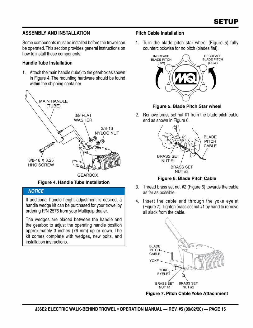
ASSEMBLY AND INSTALLATION
Some components must be installed before the trowel can be operated. This section provides general instructions on how to install these components.
Handle Tube Installation
1. Attach the main handle (tube) to the gearbox as shown in Figure 4. The mounting hardware should be found within the shipping container.
Figure 4. Handle Tube Installation
3/8 FLATWASHER
3/8-16NYLOC NUT
3/8-16 X 3.25HHC SCREW
MAIN HANDLE(TUBE)
GEARBOX
NOTICE
If additional handle height adjustment is desired, a handle wedge kit can be purchased for your trowel by ordering P/N 2576 from your Multiquip dealer.
The wedges are placed between the handle and the gearbox to adjust the operating handle position approximately 3 inches (76 mm) up or down. The kit comes complete with wedges, new bolts, and installation instructions.
Pitch Cable Installation
1. Turn the blade pitch star wheel (Figure 5) fully counterclockwise for no pitch (blades flat).
Figure 5. Blade Pitch Star wheel
2. Remove brass set nut #1 from the blade pitch cable end as shown in Figure 6.
Figure 6. Blade Pitch Cable
3. Thread brass set nut #2 (Figure 6) towards the cable as far as possible.
4. Inser t the cable end through the yoke eyelet (Figure 7). Tighten brass set nut #1 by hand to remove all slack from the cable.
Figure 7. Pitch Cable Yoke Attachment
INCREASEBLADE PITCH
(CW)
DECREASEBLADE PITCH
(CCW)
BLADEPITCHCABLE
BRASS SETNUT #1
BRASS SETNUT #2
BRASS SETNUT #1
BRASS SETNUT #2
YOKEEYELET
YOKE
BLADEPITCHCABLE

PAGE 16 — J36E2 ELECTRIC WALK-BEHIND TROWEL • OPERATION MANUAL — REV. #5 (09/02/20)
5. Using a wrench, tighten brass set nut #2 against the yoke boss. This will lock the cable in place.
6. Use a wrench to finish tightening brass set nut #1 against the yoke boss.
GEARBOX OIL
1. Determine if gearbox oil is low by removing the oil plug located on the side of the gearbox (Figure 8). This plug will be marked by the ‘check’ decal. The correct level of gearbox oil is to the bottom of the fill plug.
Figure 8. Gearbox Oil
2. If oil begins to seep out as the drain plug is removed, the gearbox has a sufficient amount of oil.
3. If oil does not seep out as the drain plug is removed, fill with Chevron Cetus® HiPerSYN® 460 synthetic oil until the oil filler hole begins to overflow.
V-BELT
A worn or damaged V-belt can adversely affect the performance of the trowel. If the V-belt is defective or worn simply replace the V-belt as outlined in the Maintenance section of this manual.
BELT GUARD
Check the belt guard for damage or loose or missing hardware.
BLADES
Check for worn or damaged blades. Check to see if one blade is worn out while the others look new. If this is the case there could be a blade pitch problem. Refer to the Maintenance section of this manual for the blade pitch adjustment procedure. Replace any worn blades.
OIL FILLPLUG
GEARBOX
INSPECTION
OPERATOR PRESENCE ON/OFF LEVER SWITCH
This trowel is equipped with an operator presence ON/OFF lever switch (Figure 9). This switch should be tested every time the motor is started.
The purpose of the switch is to stop the electric motor during a runaway situation (i.e. the operator releases the handle during operation).
Figure 9. Operator Presence Switch
WARNING
NEVER disable or disconnect the operator presence ON/OFF lever switch. It is provided for operator safety. Injury may result if it is disabled, disconnected or improperly maintained.
OPERATOR
PRESENCE
ON/OFF
LEVER SWITCH
POWER
ON
OFF
(CENTER)
J36E2 ELECTRIC WALK-BEHIND TROWEL • OPERATION MANUAL — REV. #5 (09/02/20) — PAGE 17
OPERATION
This section is intended to assist the operator with the initial startup and operation of the walk-behind trowel. It is extremely important that this section be read carefully before attempting to use the trowel in the field. DO NOT use your trowel until this section is thoroughly understood.
LIFTING THE TROWEL ONTO A CONCRETE SLAB
CAUTION
ALWAYS wear approved eye and hearing protection while operating the trowel.
NEVER place hands or feet inside the guard rings while the electric motor is running.
NOTICE
DO NOT attempt to operate the trowel until the Safety, General Information, and Inspection sections of this manual have been read and thoroughly understood.
WARNING
Extra care should be taken when lifting the trowel off the ground. Serious damage to the machine or personal injury could be caused by dropping a trowel.
WARNING
NEVER attempt to lift the trowel alone. ALWAYS use two people when lifting of the trowel is required. BE CAREFUL when lifting the trowel by the guard ring as it may rotate and cause injury.
WARNING
NEVER lift the trowel to unnecessary heights. NEVER stand underneath the trowel while it is being lifted. Serious damage to the machine or personal injury could be caused by a dropped trowel.
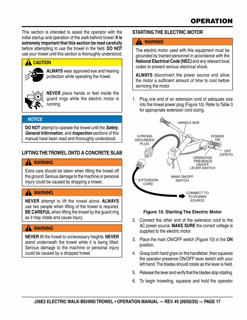
STARTING THE ELECTRIC MOTOR
1. Plug one end of an extension cord of adequate size into the trowel power plug (Figure 10). Refer to Table 3 for appropriate extension cord sizing.
Figure 10. Starting The Electric Motor
2. Connect the other end of the extension cord to the AC power source. MAKE SURE the correct voltage is supplied to the electric motor.
3. Place the main ON/OFF switch (Figure 10) in the ON position.
4. Grasp both hand grips on the handlebar, then squeeze the operator presence ON/OFF lever switch with your left hand. The blades should rotate as the lever is held.
5. Release the lever and verify that the blades stop rotating.
6. To begin troweling, squeeze and hold the operator
WARNING
The electric motor used with this equipment must be grounded by trained personnel in accordance with the National Electrical Code (NEC) and any relevant local codes to prevent serious electrical shock.
ALWAYS disconnect the power source and allow the motor a sufficient amount of time to cool before servicing the motor.
MAIN ON/OFFSWITCH
3-PRONGGROUNDED
PLUG
OPERATOR PRESENCE
ON/OFFLEVER SWITCH
POWERON
OFF(CENTER)
CONNECT TOTO POWER
SOURCE
HANDLE BAR
EXTENSIONCORD
PAGE 18 — J36E2 ELECTRIC WALK-BEHIND TROWEL • OPERATION MANUAL — REV. #5 (09/02/20)
presence lever switch. To stop troweling, release the lever.
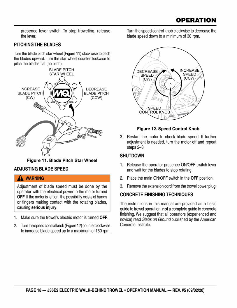
PITCHING THE BLADES
Turn the blade pitch star wheel (Figure 11) clockwise to pitch the blades upward. Turn the star wheel counterclockwise to pitch the blades flat (no pitch).
Figure 11. Blade Pitch Star Wheel
ADJUSTING BLADE SPEED
1. Make sure the trowel’s electric motor is turned OFF.
2. Turn the speed control knob (Figure 12) counterclockwise to increase blade speed up to a maximum of 160 rpm.
INCREASE
BLADE PITCH
(CW)
DECREASE
BLADE PITCH
(CCW)
BLADE PITCH
STAR WHEEL
WARNING
Adjustment of blade speed must be done by the operator with the electrical power to the motor turned OFF. If the motor is left on, the possibility exists of hands or fingers making contact with the rotating blades, causing serious injury.
OPERATION
Turn the speed control knob clockwise to decrease the blade speed down to a minimum of 30 rpm.
Figure 12. Speed Control Knob
3. Restart the motor to check blade speed. If further adjustment is needed, turn the motor off and repeat steps 2–3.
SHUTDOWN
1. Release the operator presence ON/OFF switch lever and wait for the blades to stop rotating.
2. Place the main ON/OFF switch in the OFF position.
3. Remove the extension cord from the trowel power plug.
CONCRETE FINISHING TECHNIQUES
The instructions in this manual are provided as a basic guide to trowel operation, not a complete guide to concrete finishing. We suggest that all operators (experienced and novice) read Slabs on Ground published by the American Concrete Institute.
SPEEDCONTROL KNOB
INCREASESPEED(CCW)
DECREASESPEED(CW)
J36E2 ELECTRIC WALK-BEHIND TROWEL • OPERATION MANUAL — REV. #5 (09/02/20) — PAGE 19
OPERATION
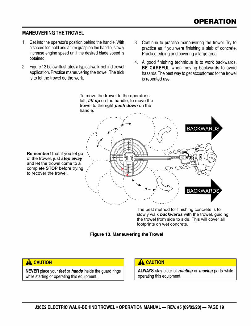
To move the trowel to the operator’sleft, on the handle, to move thetrowel to the right on thehandle.
lift uppush down
Remember!
STOP
that if you let goof the trowel, justand let the trowel come to acomplete before tryingto recover the trowel.
step away
The best method for finishing concrete is toslowly walk with the trowel, guidingthe trowel from side to side. This will cover allfootprints on wet concrete.
backwards
BACKWARDS
BACKWARDS
Figure 13. Maneuvering the Trowel
CAUTION
NEVER place your feet or hands inside the guard rings while starting or operating this equipment.
CAUTION
ALWAYS stay clear of rotating or moving parts while operating this equipment.
MANEUVERING THE TROWEL
1. Get into the operator’s position behind the handle. With a secure foothold and a firm grasp on the handle, slowly increase engine speed until the desired blade speed is obtained.
2. Figure 13 below illustrates a typical walk-behind trowel application. Practice maneuvering the trowel. The trick is to let the trowel do the work.
3. Continue to practice maneuvering the trowel. Try to practice as if you were finishing a slab of concrete. Practice edging and covering a large area.
4. A good finishing technique is to work backwards. BE CAREFUL when moving backwards to avoid hazards. The best way to get accustomed to the trowel is repeated use.
PAGE 20 — J36E2 ELECTRIC WALK-BEHIND TROWEL • OPERATION MANUAL — REV. #5 (09/02/20)
OPTIONS
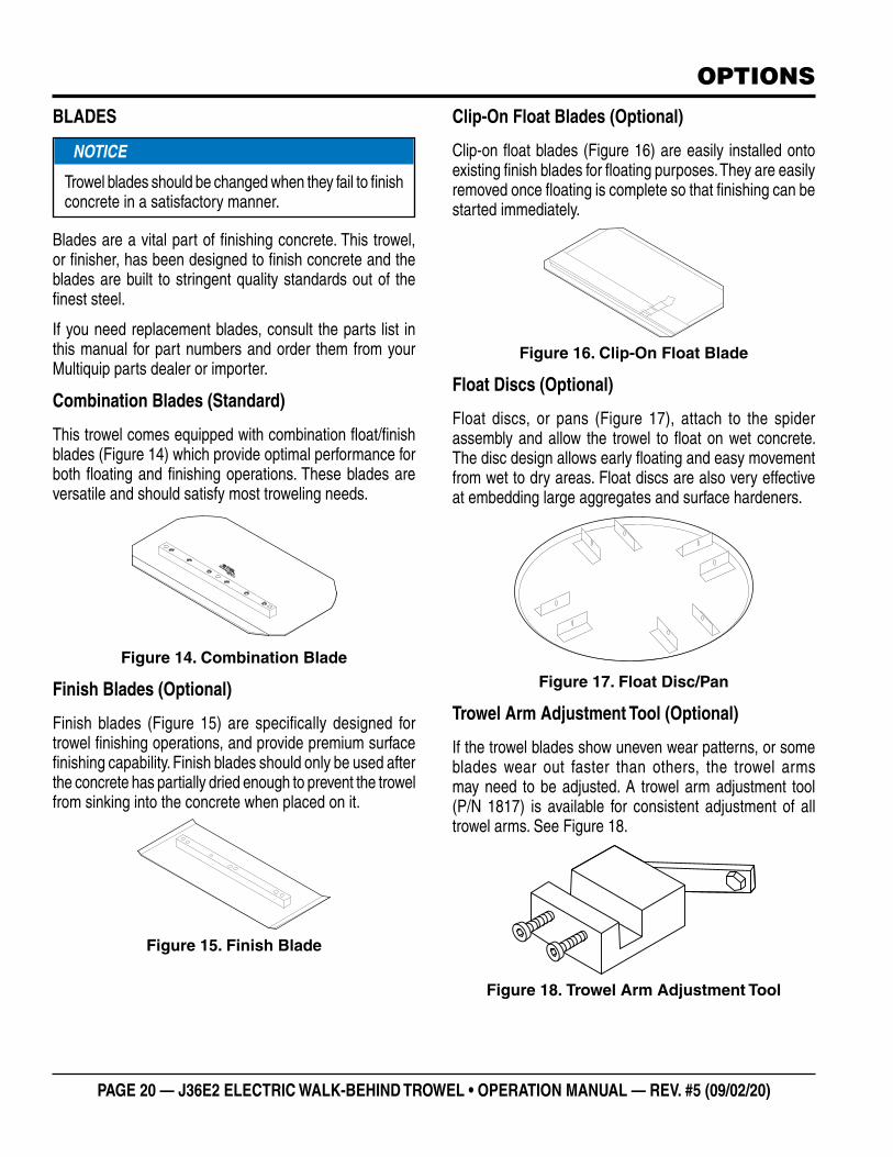
BLADES
Blades are a vital part of finishing concrete. This trowel, or finisher, has been designed to finish concrete and the blades are built to stringent quality standards out of the finest steel.
If you need replacement blades, consult the parts list in this manual for part numbers and order them from your Multiquip parts dealer or importer.
Combination Blades (Standard)
This trowel comes equipped with combination float/finish blades (Figure 14) which provide optimal performance for both floating and finishing operations. These blades are versatile and should satisfy most troweling needs.
Figure 14. Combination Blade
Finish Blades (Optional)
Finish blades (Figure 15) are specifically designed for trowel finishing operations, and provide premium surface finishing capability. Finish blades should only be used after the concrete has partially dried enough to prevent the trowel from sinking into the concrete when placed on it.
Figure 15. Finish Blade
NOTICE
Trowel blades should be changed when they fail to finish concrete in a satisfactory manner.
Clip-On Float Blades (Optional)
Clip-on float blades (Figure 16) are easily installed onto existing finish blades for floating purposes. They are easily removed once floating is complete so that finishing can be started immediately.
Figure 16. Clip-On Float Blade
Float Discs (Optional)
Float discs, or pans (Figure 17), attach to the spider assembly and allow the trowel to float on wet concrete. The disc design allows early floating and easy movement from wet to dry areas. Float discs are also very effective at embedding large aggregates and surface hardeners.
Figure 17. Float Disc/Pan
Trowel Arm Adjustment Tool (Optional)
If the trowel blades show uneven wear patterns, or some blades wear out faster than others, the trowel arms may need to be adjusted. A trowel arm adjustment tool (P/N 1817) is available for consistent adjustment of all trowel arms. See Figure 18.
Figure 18. Trowel Arm Adjustment Tool
J36E2 ELECTRIC WALK-BEHIND TROWEL • OPERATION MANUAL — REV. #5 (09/02/20) — PAGE 21
MAINTENANCE
Table 4. Trowel Maintenance Schedule
Item Operation DailyPeriodic Maintenance Interval
Every 50–60 Hrs.
Every 200–300 Hrs.
Every 2000–2500 Hrs.
V-Belt Check/Replace XRelube Trowel Arms Grease XBlades Check/Replace XTrowel Arms Remove/Clean XThrust Collar/Bushing Remove/Clean XBlade Arms Adjust XArm Bushing Remove/Replace XWear Ring Remove/Replace XThrust Collar Bearing Remove/Replace XPitch Control Cable Check X
General maintenance practices are crucial to the performance and longevity of your trowel. This equipment requires routine cleaning, blade and trowel arm inspection, lubrication, and V-belt inspection for wear and damage. Refer to Table 4 for scheduled trowel maintenance.
The following maintenance procedures can prevent serious trowel damage or malfunction.
GENERAL CLEANLINESS
Clean the trowel daily. Remove all dust and slurry buildup. If the trowel is steam cleaned, ensure that lubrication is performed AFTER steam cleaning.
ELECTRIC MOTOR
The electric motor bearing is prelubricated. No further lubrication or maintenance is required.
WARNING
ALWAYS disconnect power from the electric motor before performing maintenance on the trowel.
WARNING
NEVER place hands or feet inside the guard rings while the electric motor is running.
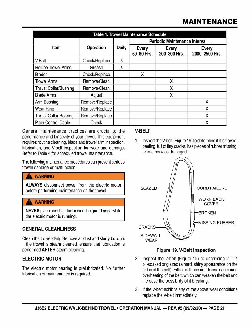
V-BELT
1. Inspect the V-belt (Figure 19) to determine if it is frayed, peeling, full of tiny cracks, has pieces of rubber missing, or is otherwise damaged.
Figure 19. V-Belt Inspection
2. Inspect the V-belt (Figure 19) to determine if it is oil-soaked or glazed (a hard, shiny appearance on the sides of the belt). Either of these conditions can cause overheating of the belt, which can weaken the belt and increase the possibility of it breaking.
3. If the V-belt exhibits any of the above wear conditions replace the V-belt immediately.
GLAZED
BROKEN
CORD FAILURE
CRACKSMISSING RUBBER
SIDEWALLWEAR
WORN BACKCOVER
PAGE 22 — J36E2 ELECTRIC WALK-BEHIND TROWEL • OPERATION MANUAL — REV. #5 (09/02/20)
MAINTENANCE
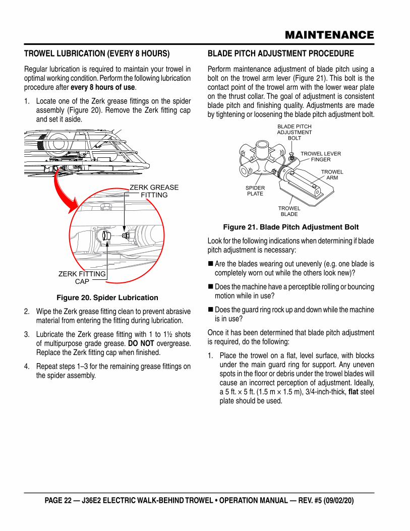
TROWEL LUBRICATION (EVERY 8 HOURS)
Regular lubrication is required to maintain your trowel in optimal working condition. Perform the following lubrication procedure after every 8 hours of use.
1. Locate one of the Zerk grease fittings on the spider assembly (Figure 20). Remove the Zerk fitting cap and set it aside.
Figure 20. Spider Lubrication
2. Wipe the Zerk grease fitting clean to prevent abrasive material from entering the fitting during lubrication.
3. Lubricate the Zerk grease fitting with 1 to 1½ shots of multipurpose grade grease. DO NOT overgrease. Replace the Zerk fitting cap when finished.
4. Repeat steps 1–3 for the remaining grease fittings on the spider assembly.
ZERK FITTING CAP
ZERK GREASEFITTING
BLADE PITCH ADJUSTMENT PROCEDURE
Perform maintenance adjustment of blade pitch using a bolt on the trowel arm lever (Figure 21). This bolt is the contact point of the trowel arm with the lower wear plate on the thrust collar. The goal of adjustment is consistent blade pitch and finishing quality. Adjustments are made by tightening or loosening the blade pitch adjustment bolt.
Figure 21. Blade Pitch Adjustment Bolt
Look for the following indications when determining if blade pitch adjustment is necessary:
�Are the blades wearing out unevenly (e.g. one blade is completely worn out while the others look new)?
�Does the machine have a perceptible rolling or bouncing motion while in use?
�Does the guard ring rock up and down while the machine is in use?
Once it has been determined that blade pitch adjustment is required, do the following:
1. Place the trowel on a flat, level surface, with blocks under the main guard ring for support. Any uneven spots in the floor or debris under the trowel blades will cause an incorrect perception of adjustment. Ideally, a 5 ft. × 5 ft. (1.5 m × 1.5 m), 3/4-inch-thick, flat steel plate should be used.
SPIDERPLATE
BLADE PITCHADJUSTMENT
BOLT
TROWELARM
TROWEL LEVERFINGER
TROWELBLADE
J36E2 ELECTRIC WALK-BEHIND TROWEL • OPERATION MANUAL — REV. #5 (09/02/20) — PAGE 23
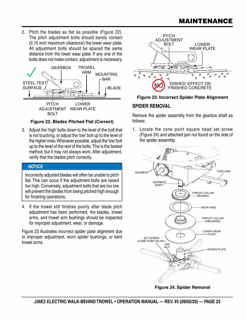
2. Pitch the blades as flat as possible (Figure 22). The pitch adjustment bolts should barely contact (0.10 inch maximum clearance) the lower wear plate. All adjustment bolts should be spaced the same distance from the lower wear plate. If any one of the bolts does not make contact, adjustment is necessary.
Figure 22. Blades Pitched Flat (Correct)
3. Adjust the ‘high’ bolts down to the level of the bolt that is not touching, or adjust the ‘low’ bolt up to the level of the higher ones. Whenever possible, adjust the ‘low’ bolt up to the level of the rest of the bolts. This is the fastest method, but it may not always work. After adjustment, verify that the blades pitch correctly.
4. If the trowel still finishes poorly after blade pitch adjustment has been performed, the blades, trowel arms, and trowel arm bushings should be inspected for improper adjustment, wear, or damage.
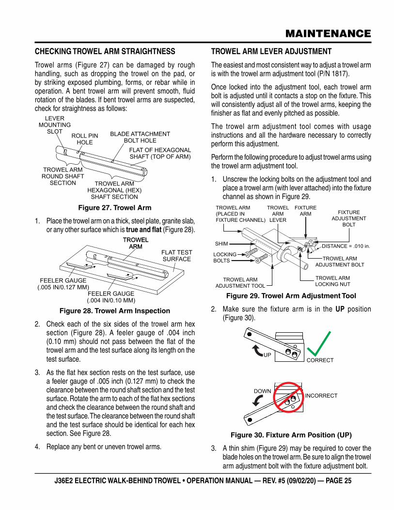
Figure 23 illustrates incorrect spider plate alignment due to improper adjustment, worn spider bushings, or bent trowel arms.
GEARBOX
BLADE
TROWELARM MOUNTING
BAR
LOWERWEAR PLATE
PITCHADJUSTMENT
BOLT
STEEL TESTSURFACE
NOTICE
Incorrectly adjusted blades will often be unable to pitch flat. This can occur if the adjustment bolts are raised too high. Conversely, adjustment bolts that are too low will prevent the blades from being pitched high enough for finishing operations.
MAINTENANCE
Figure 23. Incorrect Spider Plate Alignment
SPIDER REMOVAL
Remove the spider assembly from the gearbox shaft as follows:
1. Locate the cone point square head set screw (Figure 24) and attached jam nut found on the side of the spider assembly.
Figure 24. Spider Removal
NO
LOWERWEAR PLATE
PITCHADJUSTMENT
BOLT
‘DISHED’ EFFECT ONFINISHED CONCRETE
GEARBOX
GEARBOXSHAFT
THRUST COLLARBEARING
THRUST COLLARW/BUSHING
WEAR RING
LOWER WEARPLATE
SPIDER PLATE
JAMNUT
SET SCREW(CONE POINT SQ.HD.)
YOKE ARM

PAGE 24 — J36E2 ELECTRIC WALK-BEHIND TROWEL • OPERATION MANUAL — REV. #5 (09/02/20)
MAINTENANCE
2. Loosen the jam nut and cone point square head set screw.
3. Carefully lift the upper trowel/gearbox assembly off of the spider assembly. A slight tap with a rubber mallet may be necessary to dislodge the spider from the main shaft of the gearbox.
CHANGING BLADES
It is recommended to replace all of the trowel blades at the same time. If only one or some of the blades are changed, the machine may wobble or bounce and will not finish concrete consistently.
Perform the following procedure when changing blades:
1. Lift the trowel up and place blocks under the main guard ring to support it.
2. Remove the bolts and lock washers from all of the trowel arms, then remove the blades as shown in Figure 25.
Figure 25. Blade Removal
3. Wire brush and remove all concrete and debris from all six sides of each of the four trowel arms. This is important to properly seat the new blades.
NOTICE
Please note the orientation of each blade on the trowel arm before removing.
TROWEL ARM
BLADEATTACHMENT
SCREWS
TROWELBLADE
BLADEATTACHMENT
BAR
4. Install the new blades, maintaining the proper blade orientation for direction of rotation.
5. Reinstall the bolts and lock washers.
TROWEL ARM REMOVAL
1. Each trowel arm is held in place at the spider plate by a hex head bolt (Zerk grease fitting) and a roll pin. Remove both the hex head bolt and the roll pin from the spider plate (Figure 26).
Figure 26. Trowel Arm Removal
2. Remove the trowel arm from the spider plate.
3. Should the trowel arm insert (bushing) come out with the trowel arm, set the bushing aside in a safe place. If the bushing is retained inside the spider plate, carefully remove the bushing from the trowel arm.
4. Examine the trowel arm bushing insert, and clean it if necessary. Replace the bushing if it is out-of-round or worn.
TROWELARM
ROLL PIN
SPIDER PLATE
ZERKGREASEFITTING
CAP
BUSHING
J36E2 ELECTRIC WALK-BEHIND TROWEL • OPERATION MANUAL — REV. #5 (09/02/20) — PAGE 25
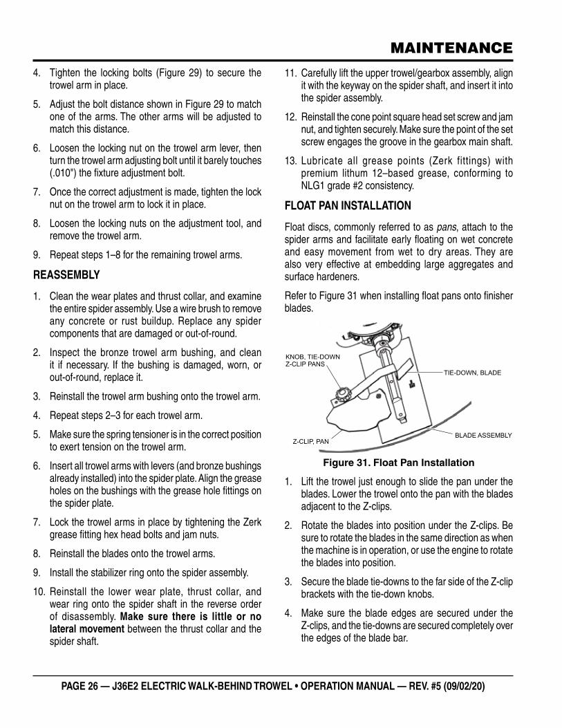
CHECKING TROWEL ARM STRAIGHTNESS
Trowel arms (Figure 27) can be damaged by rough handling, such as dropping the trowel on the pad, or by striking exposed plumbing, forms, or rebar while in operation. A bent trowel arm will prevent smooth, fluid rotation of the blades. If bent trowel arms are suspected, check for straightness as follows:
Figure 27. Trowel Arm
1. Place the trowel arm on a thick, steel plate, granite slab, or any other surface which is true and flat (Figure 28).
Figure 28. Trowel Arm Inspection
2. Check each of the six sides of the trowel arm hex section (Figure 28). A feeler gauge of .004 inch (0.10 mm) should not pass between the flat of the trowel arm and the test surface along its length on the test surface.
3. As the flat hex section rests on the test surface, use a feeler gauge of .005 inch (0.127 mm) to check the clearance between the round shaft section and the test surface. Rotate the arm to each of the flat hex sections and check the clearance between the round shaft and the test surface. The clearance between the round shaft and the test surface should be identical for each hex section. See Figure 28.
4. Replace any bent or uneven trowel arms.
TROWEL ARMROUND SHAFT
SECTION
ROLL PINHOLE
BLADE ATTACHMENTBOLT HOLE
FLAT OF HEXAGONALSHAFT (TOP OF ARM)
LEVERMOUNTING
SLOT
TROWEL ARMHEXAGONAL (HEX)
SHAFT SECTION
TROWELARM
TROWELARM
FLAT TESTSURFACE
FEELER GAUGE(.004 IN/0.10 MM)
FEELER GAUGE(.005 IN/0.127 MM)
MAINTENANCE
TROWEL ARM LEVER ADJUSTMENT
The easiest and most consistent way to adjust a trowel arm is with the trowel arm adjustment tool (P/N 1817).
Once locked into the adjustment tool, each trowel arm bolt is adjusted until it contacts a stop on the fixture. This will consistently adjust all of the trowel arms, keeping the finisher as flat and evenly pitched as possible.
The trowel arm adjustment tool comes with usage instructions and all the hardware necessary to correctly perform this adjustment.
Perform the following procedure to adjust trowel arms using the trowel arm adjustment tool.
1. Unscrew the locking bolts on the adjustment tool and place a trowel arm (with lever attached) into the fixture channel as shown in Figure 29.
Figure 29. Trowel Arm Adjustment Tool
2. Make sure the fixture arm is in the UP position (Figure 30).
Figure 30. Fixture Arm Position (UP)
3. A thin shim (Figure 29) may be required to cover the blade holes on the trowel arm. Be sure to align the trowel arm adjustment bolt with the fixture adjustment bolt.
TROWEL ARM(PLACED INFIXTURE CHANNEL)
TROWELARM
LEVERFIXTURE
ADJUSTMENTBOLT
FIXTUREARM
DISTANCE = .010 in.
TROWEL ARMADJUSTMENT TOOL
LOCKINGBOLTS
SHIM
TROWEL ARMLOCKING NUT
TROWEL ARMADJUSTMENT BOLT
.010"
UP
DOWN
CORRECT
INCORRECT
PAGE 26 — J36E2 ELECTRIC WALK-BEHIND TROWEL • OPERATION MANUAL — REV. #5 (09/02/20)
4. Tighten the locking bolts (Figure 29) to secure the trowel arm in place.
5. Adjust the bolt distance shown in Figure 29 to match one of the arms. The other arms will be adjusted to match this distance.
6. Loosen the locking nut on the trowel arm lever, then turn the trowel arm adjusting bolt until it barely touches (.010") the fixture adjustment bolt.
7. Once the correct adjustment is made, tighten the lock nut on the trowel arm to lock it in place.
8. Loosen the locking nuts on the adjustment tool, and remove the trowel arm.
9. Repeat steps 1–8 for the remaining trowel arms.
REASSEMBLY
1. Clean the wear plates and thrust collar, and examine the entire spider assembly. Use a wire brush to remove any concrete or rust buildup. Replace any spider components that are damaged or out-of-round.
2. Inspect the bronze trowel arm bushing, and clean it if necessary. If the bushing is damaged, worn, or out-of-round, replace it.
3. Reinstall the trowel arm bushing onto the trowel arm.
4. Repeat steps 2–3 for each trowel arm.
5. Make sure the spring tensioner is in the correct position to exert tension on the trowel arm.
6. Insert all trowel arms with levers (and bronze bushings already installed) into the spider plate. Align the grease holes on the bushings with the grease hole fittings on the spider plate.
7. Lock the trowel arms in place by tightening the Zerk grease fitting hex head bolts and jam nuts.
8. Reinstall the blades onto the trowel arms.
9. Install the stabilizer ring onto the spider assembly.
10. Reinstall the lower wear plate, thrust collar, and wear ring onto the spider shaft in the reverse order of disassembly. Make sure there is little or no lateral movement between the thrust collar and the spider shaft.
MAINTENANCE
11. Carefully lift the upper trowel/gearbox assembly, align it with the keyway on the spider shaft, and insert it into the spider assembly.
12. Reinstall the cone point square head set screw and jam nut, and tighten securely. Make sure the point of the set screw engages the groove in the gearbox main shaft.
13. Lubricate all grease points (Zerk fittings) with premium lithum 12–based grease, conforming to NLG1 grade #2 consistency.
FLOAT PAN INSTALLATION
Float discs, commonly referred to as pans, attach to the spider arms and facilitate early floating on wet concrete and easy movement from wet to dry areas. They are also very effective at embedding large aggregates and surface hardeners.
Refer to Figure 31 when installing float pans onto finisher blades.
Figure 31. Float Pan Installation
1. Lift the trowel just enough to slide the pan under the blades. Lower the trowel onto the pan with the blades adjacent to the Z-clips.
2. Rotate the blades into position under the Z-clips. Be sure to rotate the blades in the same direction as when the machine is in operation, or use the engine to rotate the blades into position.
3. Secure the blade tie-downs to the far side of the Z-clip brackets with the tie-down knobs.
4. Make sure the blade edges are secured under the Z-clips, and the tie-downs are secured completely over the edges of the blade bar.
BLADE ASSEMBLYZ-CLIP, PAN
TIE-DOWN, BLADE
KNOB, TIE-DOWNZ-CLIP PANS
J36E2 ELECTRIC WALK-BEHIND TROWEL • OPERATION MANUAL — REV. #5 (09/02/20) — PAGE 27
MAINTENANCE
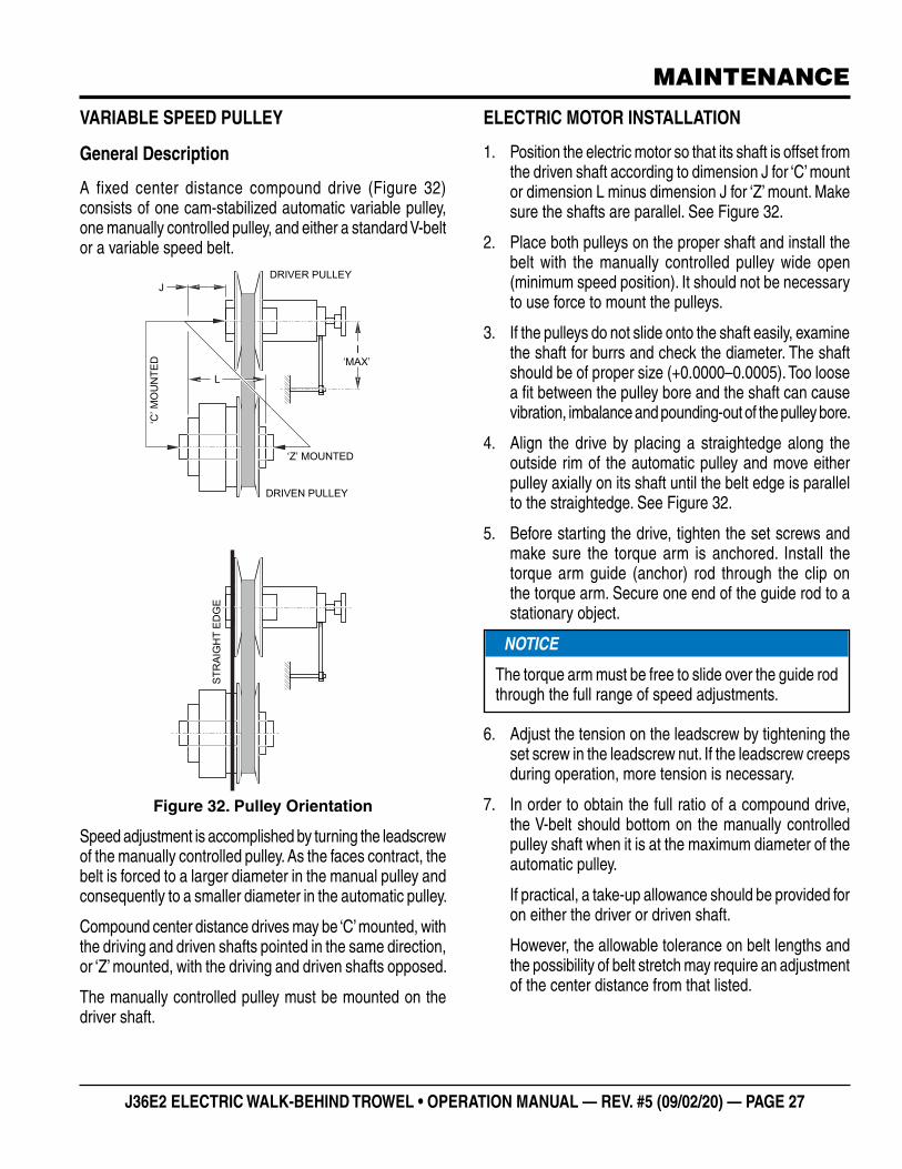
VARIABLE SPEED PULLEY
General Description
A fixed center distance compound drive (Figure 32) consists of one cam-stabilized automatic variable pulley, one manually controlled pulley, and either a standard V-belt or a variable speed belt.
Figure 32. Pulley Orientation
Speed adjustment is accomplished by turning the leadscrew of the manually controlled pulley. As the faces contract, the belt is forced to a larger diameter in the manual pulley and consequently to a smaller diameter in the automatic pulley.
Compound center distance drives may be ‘C’ mounted, with the driving and driven shafts pointed in the same direction, or ‘Z’ mounted, with the driving and driven shafts opposed.
The manually controlled pulley must be mounted on the driver shaft.
DRIVER PULLEY
DRIVEN PULLEY
‘Z’ MOUNTED
I‘MAX’
L
J
‘C’ M
OU
NTE
D
STR
AIG
HT
EDG
E
ELECTRIC MOTOR INSTALLATION
1. Position the electric motor so that its shaft is offset from the driven shaft according to dimension J for ‘C’ mount or dimension L minus dimension J for ‘Z’ mount. Make sure the shafts are parallel. See Figure 32.
2. Place both pulleys on the proper shaft and install the belt with the manually controlled pulley wide open (minimum speed position). It should not be necessary to use force to mount the pulleys.
3. If the pulleys do not slide onto the shaft easily, examine the shaft for burrs and check the diameter. The shaft should be of proper size (+0.0000–0.0005). Too loose a fit between the pulley bore and the shaft can cause vibration, imbalance and pounding-out of the pulley bore.
4. Align the drive by placing a straightedge along the outside rim of the automatic pulley and move either pulley axially on its shaft until the belt edge is parallel to the straightedge. See Figure 32.
5. Before starting the drive, tighten the set screws and make sure the torque arm is anchored. Install the torque arm guide (anchor) rod through the clip on the torque arm. Secure one end of the guide rod to a stationary object.
6. Adjust the tension on the leadscrew by tightening the set screw in the leadscrew nut. If the leadscrew creeps during operation, more tension is necessary.
7. In order to obtain the full ratio of a compound drive, the V-belt should bottom on the manually controlled pulley shaft when it is at the maximum diameter of the automatic pulley.
If practical, a take-up allowance should be provided for on either the driver or driven shaft.
However, the allowable tolerance on belt lengths and the possibility of belt stretch may require an adjustment of the center distance from that listed.
NOTICE
The torque arm must be free to slide over the guide rod through the full range of speed adjustments.

PAGE 28 — J36E2 ELECTRIC WALK-BEHIND TROWEL • OPERATION MANUAL — REV. #5 (09/02/20)
MAINTENANCE
DISASSEMBLY
1. Remove the handwheel (Figure 33) from the leadscrew. Screw in the leadscrew until the front disc comes off the shaft.
Figure 33. Drive Pulley Components
2. The bearing housing (Figure 33) will push the lube seal out of the front disc.
3. Remove the shaft bearing (Figure 33) by removing the retaining ring and pushing against the inside end of the leadscrew in an arbor press.
NOTICE
LUBRICATION: The fixed-center compound drive pulley has oil-impregnated sintered bushings on all bearing surfaces and under normal operating conditions will not require lubrication for the life of the pulley. Ball bearings in the manual control are permanently lubricated.
NOTICE
CLEANING: Foreign matter may collect in the moving parts of the pulley causing them to stick or freeze. If this occurs, disassemble the pulley (see following section on disassembly) and clean the slide disc bushing and shaft thoroughly with a solvent. After cleaning, relubricate the pulley by wiping a film of grease on all bearing surfaces.
HANDWHEELLEAD SCREW NUT ASSY.
SLIDE FACE BEARING
SET SCREW
LEAD SCREW
STOP NUT
BEARING SEATWASHERS
BEARING SEAT
FLEX-LOC NUT
TORQUE ARMASSY
SLIDE DISC
RETAININGRING
SHAFT BEARING
SET SCREW
BEARING HOUSING
COTTER PIN
COTTER PIN
LUBE SEAL
SET SCREW
COTTER PIN
SET SCREW
SET SCREW
SHAFT DISCBUSHING
4. Remove the disc bearing by pushing against the outer face of the bearing from the profile end of the front disc. Use extreme care while removing the bearings as they are easily damaged.
LONG-TERM STORAGE
When storing the trowel for more than 30 days, clean all external components of the trowel with a cloth, then cover the trowel and store it away from direct sunlight in a clean, dry location.
NOTICE
Before the parts are removed, they should be line-marked so they can be reassembled in the correct order.
Reassemble all of the parts onto the pulley shaft in the reverse sequence in which they were removed for placement under the arbor press.

J36E2 ELECTRIC WALK-BEHIND TROWEL • OPERATION MANUAL — REV. #5 (09/02/20) — PAGE 29
TROUBLESHOOTING
Troubleshooting (Walk-Behind Trowel)
Symptom Possible Problem Solution
Trowel bounces, rolls concrete, or makes uneven swirls in concrete.
Blades?
Make certain blades are in good condition, not excessively worn. Finish blades should measure no less than 2"" (50mm) from the blade bar to the trailing edge, combo blades should measure no less that 3.5"" (89mm). Trailing edge of blade should be straight and parallel to the blade bar.
Pitch adjustment?
Check that all blades are set at the same pitch angle as measured at the spider. A fi eld adjustment tool is available for height adjustment of the trowel arms. (Contact Parts Dept.)
Bent trowel arms?Check the spider assembly for bent trowel arms. If one of the arms is even slightly bent, replace it immediately.
Spider?
Check fi t of arms in spider. This can be done by moving the trowel arms up and down. If there is more than 1/8 inch (3.2 mm) of travel at the tip of the arm, the spider and arms should be replaced.
Thrust collar?Check the fl atness of the thrust collar by rotating it on the spider. If it varies by more than 0.02 inch (0.5 mm) replace the thrust collar.
Thrust collar bushing?
Check the thrust collar by rocking it on the spider. If it can tilt more than 3/32 inch (2.4 mm) - as measured at the thrust collar O.D., replace the thrust collar.
Thrust bearing worn? Check the thrust bearing to see that it is spinning freely. Replace if necessary.
Machine has a perceptible rolling motion while running
Main shaft?
The main output shaft of the gearbox assembly should be checked for straightness. The main shaft must run straight and cannot be more than 0.003"" (0.08 mm) out of round at the spider attachment point.
Yoke?Check to make sure that both fi ngers of the yoke press evenly on the wear cap. Replace yoke as necessary.
Blade Pitch?Check to ensure that each blade is adjusted to have the same pitch as all other blades. Adjust per maintenance section in manual.
Troubleshooting (Electric Motor)Symptom Possible Cause Solution
Electric motor will not start.
Is there power? Check power source. Check reset button.
Is power cable plugged in? Plug in power cable.Is ON/OFF switch placed in ON position? Place ON/OFF switch in ON position.
Defective cable? Check cable.Electric motor continuously stops. Reset button OK? Check power source.Electric motor RPM's too low. Low voltage? Check input voltage.Electric motor RPM's too high. High voltage? Check input voltage.
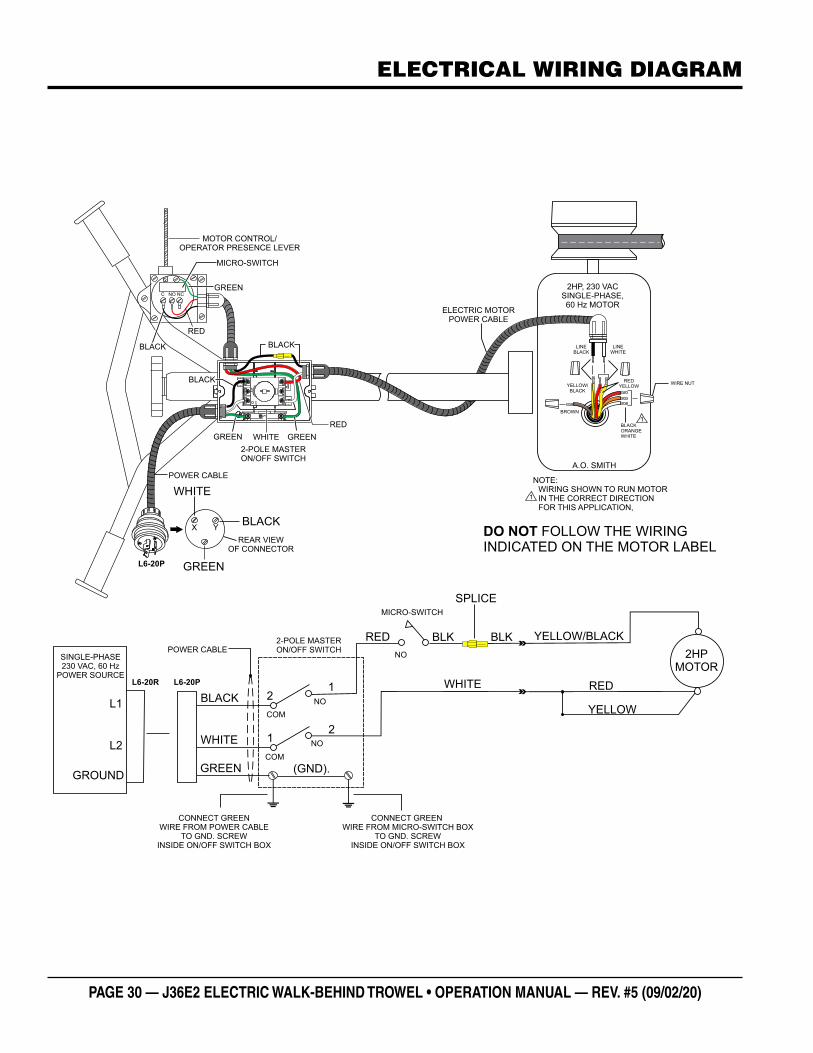
PAGE 30 — J36E2 ELECTRIC WALK-BEHIND TROWEL • OPERATION MANUAL — REV. #5 (09/02/20)
BLACK
RED
NOC NC
RED
BLACK
WHITE
MICRO-SWITCH
2-POLE MASTER ON/OFF SWITCH
MOTOR CONTROL/OPERATOR PRESENCE LEVER
X Y
GREEN
BLACK
WHITE
REAR VIEWOF CONNECTOR
WHITE
BLACK NO
1
2
RED
NO
COM
COM
NO
MICRO-SWITCH
WHITE
BLK
GREEN
CONNECT GREENWIRE FROM POWER CABLE
TO GND. SCREWINSIDE ON/OFF SWITCH BOX
YELLOW/BLACK
2HPMOTOR
2-POLE MASTER ON/OFF SWITCH
YELLOW
RED
BROWN
YELLOW/BLACK
BLACKORANGEWHITE
REDYELLOW
LINEBLACK
LINEWHITE
WIRING SHOWN TO RUN MOTORIN THE CORRECT DIRECTION FOR THIS APPLICATION,
1
NOTE:
WIRE NUT
2HP, 230 VACSINGLE-PHASE,60 Hz MOTOR
ELECTRIC MOTORPOWER CABLE
A.O. SMITH
1
SINGLE-PHASE230 VAC, 60 Hz
POWER SOURCE
L1
GROUND
L2
2
1
L6-20P
31
5
24
6
2
5
46
13
OF
F
ON
SPLICE
DO NOT FOLLOW THE WIRINGINDICATED ON THE MOTOR LABEL
GREENGREEN
BLACK
BLK
L6-20PL6-20R
(GND).
POWER CABLE
POWER CABLE
CONNECT GREEN WIRE FROM MICRO-SWITCH BOX
TO GND. SCREW INSIDE ON/OFF SWITCH BOX
GREEN
ELECTRICAL WIRING DIAGRAM

J36E2 ELECTRIC WALK-BEHIND TROWEL • OPERATION MANUAL — REV. #5 (09/02/20) — PAGE 31
NOTES

OPERATION MANUAL
Your Local Dealer is:
HERE’S HOW TO GET HELPPLEASE HAVE THE MODEL AND SERIAL
NUMBER ON-HAND WHEN CALLING
© COPYRIGHT 2020, MULTIQUIP INC.
Multiquip Inc , the MQ logo are registered trademarks of Multiquip Inc. and may not be used, reproduced, or altered without written permission. All other trademarks are the property of their respective owners and used with permission.
This manual MUST accompany the equipment at all times. This manual is considered a permanent part of the equipment and should remain with the unit if resold.
The information and specifi cations included in this publication were in effect at the time of approval for printing. Illustrations, descriptions, references and technical data contained in this manual are for guidance only and may not be considered as binding. Multiquip Inc. reserves the right to discontinue or change specifi cations, design or the information published in this publication at any time without notice and without incurring any obligations.
UNITED STATES Multiquip Inc.
(310) 537- 3700 6141 Katella Avenue Suite 200Cypress, CA 90630 E-MAIL: [email protected]: www.multiquip.com
CANADA UNITED KINGDOM
Multiquip Multiquip (UK) Limited Head Offi ce
(450) 625-2244 4110 Industriel Boul.Laval, Quebec, Canada H7L 6V3 E-MAIL : [email protected]
0161 339 2223 Unit 2, Northpoint Industrial Estate, Globe Lane,Dukinfi eld, Cheshire SK16 4UJ E-MAIL : [email protected]
PN: 30573