Embed Size (px)
Citation preview
Revit Architecture 2010, Revit MEP 2010 and Revit Structure 2010
Model Performance TechnicalNote
March 2009
© 2009 Autodesk, Inc. All Rights Reserved. Except as otherwise permitted by Autodesk, Inc., this publication, or parts thereof, may not bereproduced in any form, by any method, for any purpose.
Certain materials included in this publication are reprinted with the permission of the copyright holder.
DisclaimerTHIS PUBLICATION AND THE INFORMATION CONTAINED HEREIN IS MADE AVAILABLE BY AUTODESK, INC. "AS IS." AUTODESK, INC. DISCLAIMSALL WARRANTIES, EITHER EXPRESS OR IMPLIED, INCLUDING BUT NOT LIMITED TO ANY IMPLIED WARRANTIES OF MERCHANTABILITY ORFITNESS FOR A PARTICULAR PURPOSE REGARDING THESE MATERIALS.
TrademarksThe following are registered trademarks or trademarks of Autodesk, Inc., in the USA and other countries: 3DEC (design/logo), 3December,3December.com, 3ds Max, ADI, Alias, Alias (swirl design/logo), AliasStudio, Alias|Wavefront (design/logo), ATC, AUGI, AutoCAD, AutoCADLearning Assistance, AutoCAD LT, AutoCAD Simulator, AutoCAD SQL Extension, AutoCAD SQL Interface, Autodesk, Autodesk Envision, AutodeskInsight, Autodesk Intent, Autodesk Inventor, Autodesk Map, Autodesk MapGuide, Autodesk Streamline, AutoLISP, AutoSnap, AutoSketch,AutoTrack, Backdraft, Built with ObjectARX (logo), Burn, Buzzsaw, CAiCE, Can You Imagine, Character Studio, Cinestream, Civil 3D, Cleaner,Cleaner Central, ClearScale, Colour Warper, Combustion, Communication Specification, Constructware, Content Explorer, Create>what's>Next>(design/logo), Dancing Baby (image), DesignCenter, Design Doctor, Designer's Toolkit, DesignKids, DesignProf, DesignServer, DesignStudio,Design|Studio (design/logo), Design Web Format, Discreet, DWF, DWG, DWG (logo), DWG Extreme, DWG TrueConvert, DWG TrueView, DXF,Ecotect, Exposure, Extending the Design Team, Face Robot, FBX, Filmbox, Fire, Flame, Flint, FMDesktop, Freewheel, Frost, GDX Driver, Gmax,Green Building Studio, Heads-up Design, Heidi, HumanIK, IDEA Server, i-drop, ImageModeler, iMOUT, Incinerator, Inferno, Inventor, InventorLT, Kaydara, Kaydara (design/logo), Kynapse, Kynogon, LandXplorer, LocationLogic, Lustre, Matchmover, Maya, Mechanical Desktop, Moonbox,MotionBuilder, Movimento, Mudbox, NavisWorks, ObjectARX, ObjectDBX, Open Reality, Opticore, Opticore Opus, PolarSnap, PortfolioWall,Powered with Autodesk Technology, Productstream, ProjectPoint, ProMaterials, RasterDWG, Reactor, RealDWG, Real-time Roto, REALVIZ,Recognize, Render Queue, Retimer,Reveal, Revit, Showcase, ShowMotion, SketchBook, Smoke, Softimage, Softimage|XSI (design/logo),SteeringWheels, Stitcher, Stone, StudioTools, Topobase, Toxik, TrustedDWG, ViewCube, Visual, Visual Construction, Visual Drainage, VisualLandscape, Visual Survey, Visual Toolbox, Visual LISP, Voice Reality, Volo, Vtour, Wire, Wiretap, WiretapCentral, XSI, and XSI (design/logo).
The following are registered trademarks or trademarks of Autodesk Canada Co. in the USA and/or Canada and other countries:Backburner,Multi-Master Editing, River, and Sparks.
The following are registered trademarks or trademarks of MoldflowCorp. in the USA and/or other countries: Moldflow, MPA, MPA(design/logo),Moldflow Plastics Advisers, MPI, MPI (design/logo), Moldflow Plastics Insight,MPX, MPX (design/logo), Moldflow Plastics Xpert.
Third Party Software Program CreditsACIS Copyright© 1989-2001 Spatial Corp. Portions Copyright© 2002 Autodesk, Inc.Flash ® is a registered trademark of Macromedia, Inc. in the United States and/or other countries.International CorrectSpell™ Spelling Correction System© 1995 by Lernout & Hauspie Speech Products, N.V. All rights reserved.InstallShield™ 3.0. Copyright© 1997 InstallShield Software Corporation. All rights reserved.PANTONE® Colors displayed in the software application or in the user documentation may not match PANTONE-identified standards. Consultcurrent PANTONE Color Publications for accurate color. PANTONE Color Data and/or Software shall not be copied onto another disk or intomemory unless as part of the execution of this Autodesk software product.Portions Copyright© 1991-1996 Arthur D. Applegate. All rights reserved.Portions of this software are based on the work of the Independent JPEG Group.RAL DESIGN© RAL, Sankt Augustin, 2002RAL CLASSIC© RAL, Sankt Augustin, 2002Representation of the RAL Colors is done with the approval of RAL Deutsches Institut für Gütesicherung und Kennzeichnung e.V. (RAL GermanInstitute for Quality Assurance and Certification, re. Assoc.), D-53757 Sankt Augustin.Typefaces from the Bitstream® typeface library copyright 1992.Typefaces from Payne Loving Trust© 1996. All rights reserved.Printed manual and help produced with Idiom WorldServer™.WindowBlinds: DirectSkin™ OCX © Stardock®
AnswerWorks 4.0 ©; 1997-2003 WexTech Systems, Inc. Portions of this software © Vantage-Knexys. All rights reserved.The Director General of the Geographic Survey Institute has issued the approval for the coordinates exchange numbered TKY2JGD for JapanGeodetic Datum 2000, also known as technical information No H1-N0.2 of the Geographic Survey Institute, to be installed and used withinthis software product (Approval No.: 646 issued by GSI, April 8, 2002).Portions of this computer program are copyright © 1995-1999 LizardTech, Inc. All rights reserved. MrSID is protected by U.S. Patent No.5,710,835. Foreign Patents Pending.Portions of this computer program are Copyright ©; 2000 Earth Resource Mapping, Inc.OSTN97 © Crown Copyright 1997. All rights reserved.OSTN02 © Crown copyright 2002. All rights reserved.OSGM02 © Crown copyright 2002, © Ordnance Survey Ireland, 2002.FME Objects Engine © 2005 SAFE Software. All rights reserved.ETABS is a registered trademark of Computers and Structures, Inc. ETABS © copyright 1984-2005 Computers and Structures, Inc. All rightsreserved.RISA is a trademark of RISA Technologies. RISA-3D copyright © 1993-2005 RISA Technologies. All rights reserved.
Portions relating to JPEG © Copyright 1991-1998 Thomas G. Lane. All rights reserved. This software is based in part on the work of the IndependentJPEG Group.Portions relating to TIFF © Copyright 1997-1998 Sam Leffler. © Copyright 1991-1997 Silicon Graphics, Inc. All rights reserved. The Tiff portionsof this software are provided by the copyright holders and contributors “as is” and any express or implied warranties, including, but not limitedto, the implied warranties or merchantability and fitness for a particular purpose are disclaimed. In no event shall the copyright owner orcontributors of the TIFF portions be liable for any direct, indirect, incidental, special, exemplary, or consequential damages (including, but notlimited to, procurement of substitute goods or services; loss of use, data, or profits; or business interruption) however caused and on any theoryof liability, whether in contract, strict liability, or tort (including negligence or otherwise) arising in any way out of the use of the TIFF portionsof this software, even if advised of the possibility of such damage. Portions of Libtiff 3.5.7 Copyright © 1988-1997 Sam Leffler. Copyright ©1991-1997 Silicon Graphics, Inc. Permission to use, copy, modify, distribute, and sell this software and its documentation for any purpose ishereby granted without fee, provided that (i) the above copyright notices and this permission notice appear in all copies of the software andrelated documentation, and (ii) the names of Sam Leffler and Silicon Graphics may not be used in any advertising or publicity relating to thesoftware without the specific, prior written permission of Sam Leffler and Silicon Graphics.Portions of Libxml2 2.6.4 Copyright © 1998-2003 Daniel Veillard. All Rights Reserved. Permission is hereby granted, free of charge, to any personobtaining a copy of this software and associated documentation files (the “Software”), to deal in the Software without restriction, includingwithout limitation the rights to use, copy, modify, merge, publish, distribute, sublicense, and/or sell copies of the Software, and to permitpersons to whom the Software is furnished to do so, subject to the following conditions: The above copyright notices and this permission noticeshall be included in all copies or substantial portions of the Software.
Government UseUse, duplication, or disclosure by the U.S. Government is subject to restrictions as set forth in FAR 12.212 (Commercial ComputerSoftware-Restricted Rights) and DFAR 227.7202 (Rights in Technical Data and Computer Software), as applicable.

Contents
Chapter 1 Model Performance Technical Note . . . . . . . . . . . . . . . . . . . . . . . . . . . . . . . 1Platform Hardware Requirements and Recommendations . . . . . . . . . . . . . . . . . . . . . . . . . 1Detailed Hardware Recommendations . . . . . . . . . . . . . . . . . . . . . . . . . . . . . . . . . . . 3
Central Processing Unit (CPU) . . . . . . . . . . . . . . . . . . . . . . . . . . . . . . . . . . . . 3Multiple-Core / Multiple Processors . . . . . . . . . . . . . . . . . . . . . . . . . . . . . . . . . 4CPU Performance . . . . . . . . . . . . . . . . . . . . . . . . . . . . . . . . . . . . . . . . . . . 4L2 Cache . . . . . . . . . . . . . . . . . . . . . . . . . . . . . . . . . . . . . . . . . . . . . . . 4Hard Drive . . . . . . . . . . . . . . . . . . . . . . . . . . . . . . . . . . . . . . . . . . . . . . . 5Video Cards . . . . . . . . . . . . . . . . . . . . . . . . . . . . . . . . . . . . . . . . . . . . . . 5Hardware Acceleration . . . . . . . . . . . . . . . . . . . . . . . . . . . . . . . . . . . . . . . . 5Memory . . . . . . . . . . . . . . . . . . . . . . . . . . . . . . . . . . . . . . . . . . . . . . . . 6Optimizing OS for Performance . . . . . . . . . . . . . . . . . . . . . . . . . . . . . . . . . . . 7
Operating Systems . . . . . . . . . . . . . . . . . . . . . . . . . . . . . . . . . . . . . . . . . . . . . 9Network Recommendations . . . . . . . . . . . . . . . . . . . . . . . . . . . . . . . . . . . . . . . . 10Remote Desktop Sharing . . . . . . . . . . . . . . . . . . . . . . . . . . . . . . . . . . . . . . . . . . 10User Group Comments . . . . . . . . . . . . . . . . . . . . . . . . . . . . . . . . . . . . . . . . . . 11Revit Platform Model Optimization and Best Practices . . . . . . . . . . . . . . . . . . . . . . . . . . 11
General Guidelines . . . . . . . . . . . . . . . . . . . . . . . . . . . . . . . . . . . . . . . . . 11Arrays . . . . . . . . . . . . . . . . . . . . . . . . . . . . . . . . . . . . . . . . . . . . . . . . 11Constraints . . . . . . . . . . . . . . . . . . . . . . . . . . . . . . . . . . . . . . . . . . . . . . 12Design Options . . . . . . . . . . . . . . . . . . . . . . . . . . . . . . . . . . . . . . . . . . . 12DWG Files . . . . . . . . . . . . . . . . . . . . . . . . . . . . . . . . . . . . . . . . . . . . . . 12Family Creation . . . . . . . . . . . . . . . . . . . . . . . . . . . . . . . . . . . . . . . . . . . 12Importing & Linking . . . . . . . . . . . . . . . . . . . . . . . . . . . . . . . . . . . . . . . . . 14Modeling Economically . . . . . . . . . . . . . . . . . . . . . . . . . . . . . . . . . . . . . . . 15Project Templates . . . . . . . . . . . . . . . . . . . . . . . . . . . . . . . . . . . . . . . . . . 15Railings . . . . . . . . . . . . . . . . . . . . . . . . . . . . . . . . . . . . . . . . . . . . . . . . 16Raster Images . . . . . . . . . . . . . . . . . . . . . . . . . . . . . . . . . . . . . . . . . . . . 16Stairs . . . . . . . . . . . . . . . . . . . . . . . . . . . . . . . . . . . . . . . . . . . . . . . . . 16Upgrading Linked Projects to a New Version of Revit . . . . . . . . . . . . . . . . . . . . . . . 16Views . . . . . . . . . . . . . . . . . . . . . . . . . . . . . . . . . . . . . . . . . . . . . . . . . 16Volumes - Rooms and Spaces . . . . . . . . . . . . . . . . . . . . . . . . . . . . . . . . . . . . 18
v
Worksets . . . . . . . . . . . . . . . . . . . . . . . . . . . . . . . . . . . . . . . . . . . . . . . 19Worksharing . . . . . . . . . . . . . . . . . . . . . . . . . . . . . . . . . . . . . . . . . . . . . 20
Revit Structure 2010 Software Optimization and Best Practices . . . . . . . . . . . . . . . . . . . . . 21Revit MEP 2010 Software Optimization and Best Practices . . . . . . . . . . . . . . . . . . . . . . . . 23Interacting with Autodesk Support . . . . . . . . . . . . . . . . . . . . . . . . . . . . . . . . . . . . 26
vi | Contents
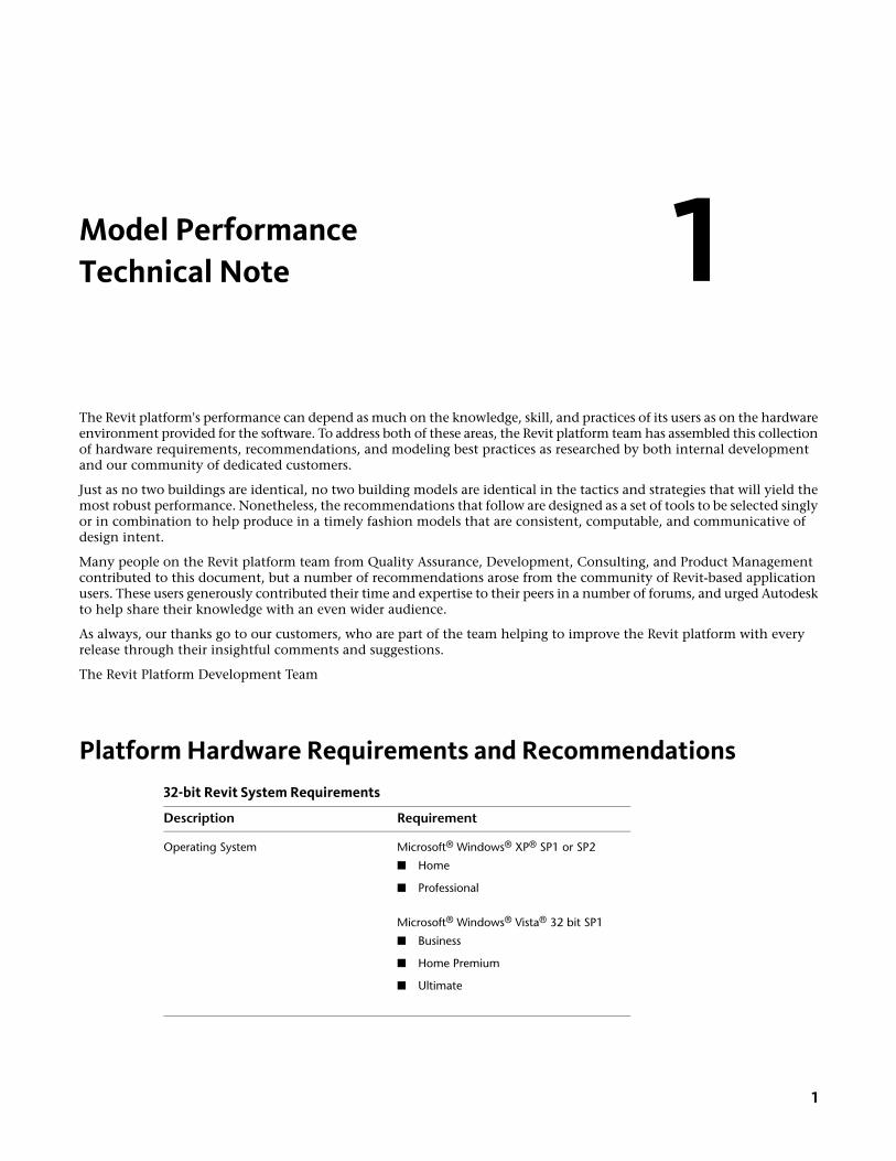
Model PerformanceTechnical Note
The Revit platform's performance can depend as much on the knowledge, skill, and practices of its users as on the hardwareenvironment provided for the software. To address both of these areas, the Revit platform team has assembled this collectionof hardware requirements, recommendations, and modeling best practices as researched by both internal developmentand our community of dedicated customers.
Just as no two buildings are identical, no two building models are identical in the tactics and strategies that will yield themost robust performance. Nonetheless, the recommendations that follow are designed as a set of tools to be selected singlyor in combination to help produce in a timely fashion models that are consistent, computable, and communicative ofdesign intent.
Many people on the Revit platform team from Quality Assurance, Development, Consulting, and Product Managementcontributed to this document, but a number of recommendations arose from the community of Revit-based applicationusers. These users generously contributed their time and expertise to their peers in a number of forums, and urged Autodeskto help share their knowledge with an even wider audience.
As always, our thanks go to our customers, who are part of the team helping to improve the Revit platform with everyrelease through their insightful comments and suggestions.
The Revit Platform Development Team
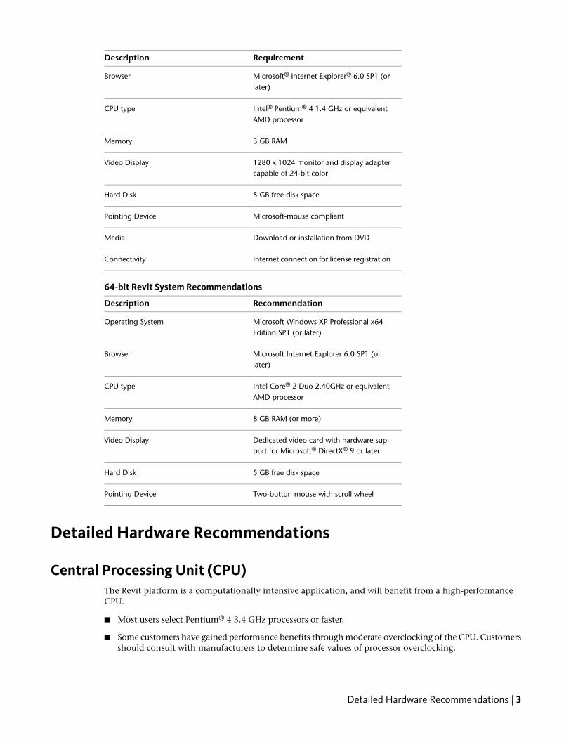
Platform Hardware Requirements and Recommendations32-bit Revit System Requirements
RequirementDescription
Microsoft® Windows® XP® SP1 or SP2Operating System
■ Home
■ Professional
Microsoft® Windows® Vista® 32 bit SP1
■ Business
■ Home Premium
■ Ultimate
1
1
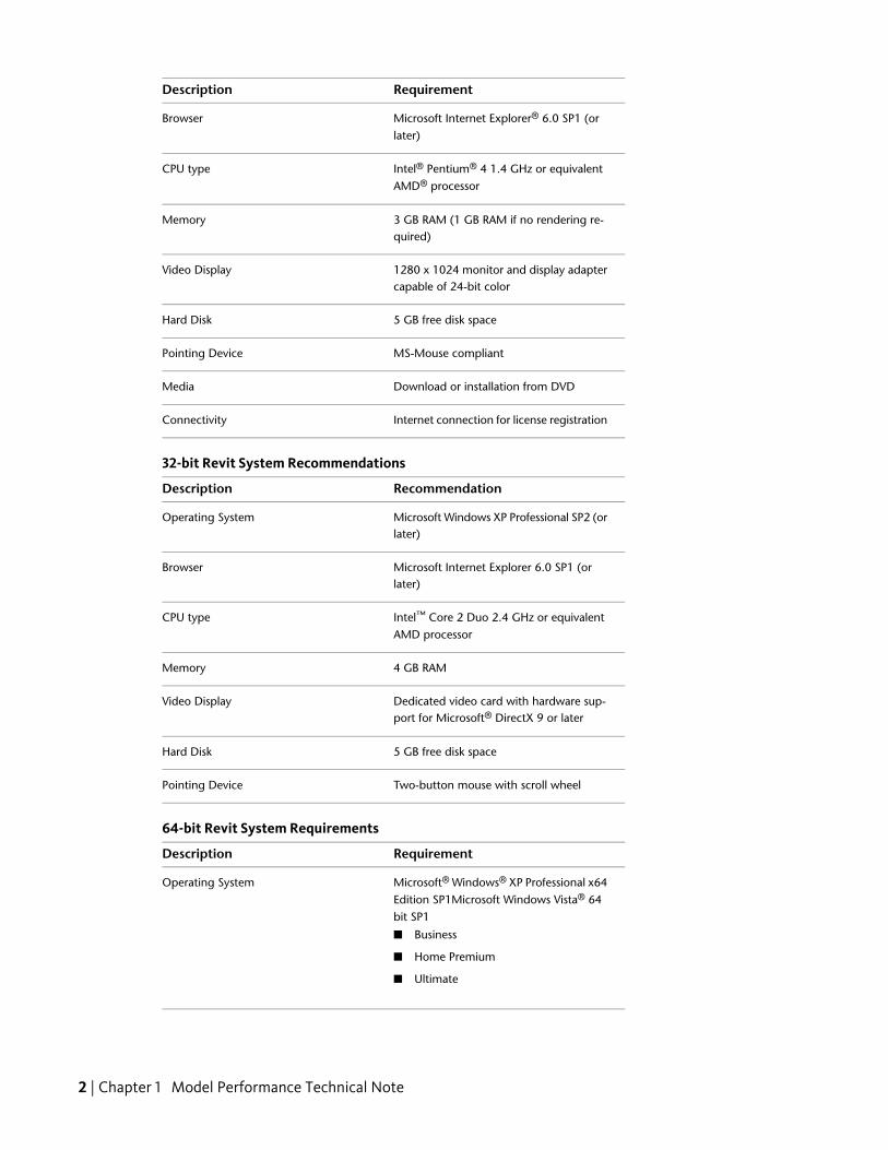
RequirementDescription
Microsoft Internet Explorer® 6.0 SP1 (orlater)
Browser
Intel® Pentium® 4 1.4 GHz or equivalentAMD® processor
CPU type
3 GB RAM (1 GB RAM if no rendering re-quired)
Memory
1280 x 1024 monitor and display adaptercapable of 24-bit color
Video Display
5 GB free disk spaceHard Disk
MS-Mouse compliantPointing Device
Download or installation from DVDMedia
Internet connection for license registrationConnectivity
32-bit Revit System Recommendations
RecommendationDescription
Microsoft Windows XP Professional SP2 (orlater)
Operating System
Microsoft Internet Explorer 6.0 SP1 (orlater)
Browser
Intel™ Core 2 Duo 2.4 GHz or equivalentAMD processor
CPU type
4 GB RAMMemory
Dedicated video card with hardware sup-port for Microsoft® DirectX 9 or later
Video Display
5 GB free disk spaceHard Disk
Two-button mouse with scroll wheelPointing Device
64-bit Revit System Requirements
RequirementDescription
Microsoft® Windows® XP Professional x64Edition SP1Microsoft Windows Vista® 64bit SP1
Operating System
■ Business
■ Home Premium
■ Ultimate
2 | Chapter 1 Model Performance Technical Note
RequirementDescription
Microsoft® Internet Explorer® 6.0 SP1 (orlater)
Browser
Intel® Pentium® 4 1.4 GHz or equivalentAMD processor
CPU type
3 GB RAMMemory
1280 x 1024 monitor and display adaptercapable of 24-bit color
Video Display
5 GB free disk spaceHard Disk
Microsoft-mouse compliantPointing Device
Download or installation from DVDMedia
Internet connection for license registrationConnectivity
64-bit Revit System Recommendations
RecommendationDescription
Microsoft Windows XP Professional x64Edition SP1 (or later)
Operating System
Microsoft Internet Explorer 6.0 SP1 (orlater)
Browser
Intel Core® 2 Duo 2.40GHz or equivalentAMD processor
CPU type
8 GB RAM (or more)Memory
Dedicated video card with hardware sup-port for Microsoft® DirectX® 9 or later
Video Display
5 GB free disk spaceHard Disk
Two-button mouse with scroll wheelPointing Device
Detailed Hardware Recommendations
Central Processing Unit (CPU)The Revit platform is a computationally intensive application, and will benefit from a high-performanceCPU.
■ Most users select Pentium® 4 3.4 GHz processors or faster.
■ Some customers have gained performance benefits through moderate overclocking of the CPU. Customersshould consult with manufacturers to determine safe values of processor overclocking.
Detailed Hardware Recommendations | 3
■ Centrino®/Pentium-M®/Core Duo® Intel processors for laptops work well with the Revit platform, andare recommended for laptops given their higher efficiency and reduced heat output. Multiply aCentrino/Pentium-M's processor speed by 1.6 to find its approximately equivalent Pentium 4 processorspeed.
Multiple-Core / Multiple Processors■ Although the Revit platform is not fully optimized for multi-threading, multiple-core processors reduce
cycle use by other applications running concurrently. Some reports show as much as a 20% increase inRevit platform performance in a multi-core or multiple processor environment.
■ In Revit 2010, multi-threaded methods for printing and wall join cleanup have been made available.Multi-threaded hidden line removal for printing has been enabled by default.
■ Due to the operating system overhead of maintaining multiple threads, multiprocessing of wall joincleanups can experience a minor degradation when only 2 CPU cores are present, but up to a 27%performance increase when 4 hyper-threaded CPU cores are present. Because 2 CPU core systems remainthe most common configuration of Revit systems as reported by CIP data, multiprocessing of this featuresis OFF by default.
■ To enable multiprocessing for wall join cleanup, add the following entries to the Revit.ini file:[PerformanceOptimizations]
ParallelWallJoins=ON
■ To disable multiprocessing for wall join cleanup, you may omit any entries in the[PerformanceOptimizations] section of the Revit.ini file, or explicitly set the state of either one or bothmultiprocessing optimizations:[PerformanceOptimizations]
ParallelWallJoins=OFF
ParallelPrintProcessing=OFF
■ The Revit platform's rendering function is optimized to use up to four processors. The Revit platformwill share processing time with one of these four rendering processors, so there is no exclusive gain forthe Revit platform in making more than four processors available. Additional processors may be desiredif other computationally-intensive applications need to run while the Revit platform is rendering.
CPU PerformanceA variety of benchmarks are available to compare CPU performance. The following links are provided as aservice to customers who may wish to do further research. Autodesk makes no warranties about the accuracyor veracity of this data:
http://www.tomshardware.com/charts/cpu-charts-2008-q1-2008/3D-Studio-Max-9,369.html
http://www.cpubenchmark.net/
http://www.spec.org/benchmarks.html
L2 CacheThe Revit platform team strongly recommends CPUs that include L2 caches because of their substantialperformance benefits. Larger L2 caches of 2MB and beyond can provide performance benefits forcomputationally-intensive operations such as model regeneration.
Processors with a smaller or no L2 cache, such as the Celeron® and Sempron® models are not recommendedfor use with the Revit platform.
4 | Chapter 1 Model Performance Technical Note
Hard Drive
Speed
Workstation hard drive speed affects Revit platform performance during model load, local model save, andhard disk swapping managed by the Microsoft Windows operating system.
If higher performance is desired during these operations, a faster hard drive may provide some benefit;however, the Revit platform team considers this workstation improvement of lower priority when comparedwith performance enhancements related to CPU speed and available RAM.
Type
SCSI or SATA drives are optional for the Revit platform.
Configuration
For the Windows operating system swap file, it is recommended that you set both the minimum andmaximum settings to the same value, which should be at least twice the value of your installed RAM. Thisapproach will prevent the Windows operating system from changing the size of the swap file while you areworking.
Defragmentation
It is recommended that you defragment local PCs and servers periodically. Highly fragmented drives maynoticeably slow PC performance.
Video Cards■ The Revit platform team strongly recommends dedicated video cards supporting DirectX 9 or later.
■ Consider video cards designed to support CAD applications.
■ Integrated video support should be avoided because such schemes use machine RAM rather than on-cardmemory.
■ Relatively inexpensive video cards may perform as well as or better than more expensive cards.
■ Revit platform rendering does not benefit from the video card graphics processing unit (GPU), nor doesit not benefit from a large amount of video RAM. 128MB of video memory should be more than sufficient.
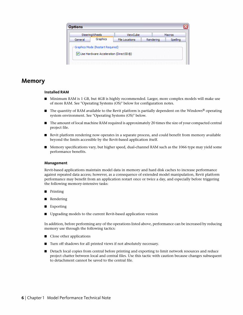
Hardware AccelerationTo take full advantage of Direct3D hardware acceleration, please follow these steps:
1 On the Revit application menu, click Options.
2 Select the Graphics tab.
3 Select the Use Hardware Acceleration (Direct 3D) option, shown below.
4 Close and restart the Revit-based application.
Hard Drive | 5
Memory
Installed RAM
■ Minimum RAM is 1 GB, but 4GB is highly recommended. Larger, more complex models will make useof more RAM. See "Operating Systems (OS)" below for configuration notes.
■ The quantity of RAM available to the Revit platform is partially dependent on the Windows® operatingsystem environment. See "Operating Systems (OS)" below.
■ The amount of local machine RAM required is approximately 20 times the size of your compacted centralproject file.
■ Revit platform rendering now operates in a separate process, and could benefit from memory availablebeyond the limits accessible by the Revit-based application itself.
■ Memory specifications vary, but higher speed, dual-channel RAM such as the 1066 type may yield someperformance benefits.
Management
Revit-based applications maintain model data in memory and hard disk caches to increase performanceagainst repeated data access; however, as a consequence of extended model manipulation, Revit platformperformance may benefit from an application restart once or twice a day, and especially before triggeringthe following memory-intensive tasks:
■ Printing
■ Rendering
■ Exporting
■ Upgrading models to the current Revit-based application version
In addition, before performing any of the operations listed above, performance can be increased by reducingmemory use through the following tactics:
■ Close other applications
■ Turn off shadows for all printed views if not absolutely necessary.
■ Detach local copies from central before printing and exporting to limit network resources and reduceproject chatter between local and central files. Use this tactic with caution because changes subsequentto detachment cannot be saved to the central file.
6 | Chapter 1 Model Performance Technical Note
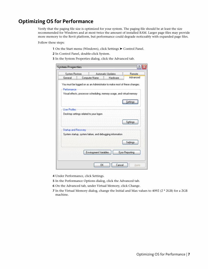
Optimizing OS for PerformanceVerify that the paging file size is optimized for your system. The paging file should be at least the sizerecommended for Windows and at most twice the amount of installed RAM. Larger page files may providemore memory to the Revit platform, but performance could degrade noticeably with expanded page files.
Follow these steps:
1 On the Start menu (Windows), click Settings ➤ Control Panel.
2 In Control Panel, double-click System.
3 In the System Properties dialog, click the Advanced tab.
4 Under Performance, click Settings.
5 In the Performance Options dialog, click the Advanced tab.
6 On the Advanced tab, under Virtual Memory, click Change.
7 In the Virtual Memory dialog, change the Initial and Max values to 4092 (2 * 2GB) for a 2GBmachine.
Optimizing OS for Performance | 7
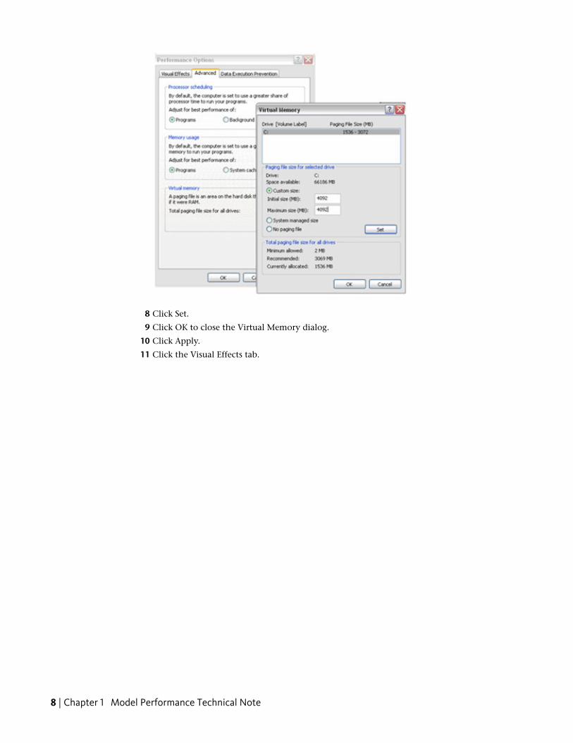
8 Click Set.
9 Click OK to close the Virtual Memory dialog.
10 Click Apply.
11 Click the Visual Effects tab.
8 | Chapter 1 Model Performance Technical Note
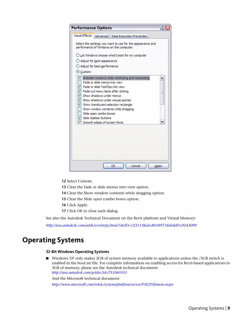
12 Select Custom.
13 Clear the Fade or slide menus into view option.
14 Clear the Show window contents while dragging option.
15 Clear the Slide open combo boxes option.
16 Click Apply.
17 Click OK to close each dialog.
See also the Autodesk Technical Document on the Revit platform and Virtual Memory:
http://usa.autodesk.com/adsk/servlet/ps/item?siteID=123112&id=8018971&linkID=9243099
Operating Systems32-Bit Windows Operating Systems
■ Windows XP only makes 2GB of system memory available to applications unless the /3GB switch isenabled in the boot.ini file. For complete information on enabling access for Revit-based applications to3GB of memory, please see the Autodesk technical document:http://usa.autodesk.com/getdoc/id=TS1060353
And the Microsoft technical document:
http://www.microsoft.com/whdc/system/platform/server/PAE/PAEmem.mspx
Operating Systems | 9

■ Windows Vista similarly limits applications to 2GB of memory use, unless the /increaseuserva 3072switch is enabled. Windows Vista no longer employs the boot.ini file. Instead, the command line utilitybcdedit must be used. Please see the Microsoft technical document:http://msdn2.microsoft.com/en-us/library/aa906211.aspx
64-Bit
■ 64-bit operating systems place no practical limit to the quantity of memory available to applications.32-bit Revit-based applications will access between 3 and 4GB of RAM in a 64-Bit OS environment if atleast 5GB of total memory is available. The Windows OS will always reserve at least 1GB of memory forOS services and hardware management. A total of 8GB of memory is recommended for such systems tomake available 4GB of memory to the Revit platform, at least 1GB for the OS, and additional memoryfor other commonly used applications to run comfortably alongside the Revit-based applications.
■ A 64-bit OS will provide similar performance to a 32-bit OS. However, due to the capability of the Revitplatform to access additional memory, 32-bit Revit may exhibit increased stability and performance whenediting larger models. 64-bit Revit is optimized to take advantage of the 64-bit Operating System.
Network RecommendationsThe Revit platform team strongly recommends a gigabit speed local area network (LAN) for worksharedprojects. The gigabit threshold should be maintained at all stages of the network, including:
■ Gigabit speed Ethernet cards at the desktop
■ Category 5e or Category 6 cabling
■ Gigabit switches
■ One or more gigabit Ethernet cards at the data storage device (server or Storage Area Network) housingthe central model
When serving a geographically diverse project team across a wide area network (WAN) the Revit platformteam strongly recommends traffic optimization and acceleration as provided by several appliances currentlyon the market.
Data Server Specification
Servers storing Revit-based application central files can benefit from:
■ Hard drive speeds as fast as economically practical
■ Multiple processors
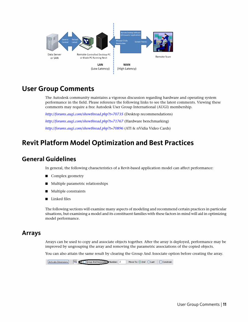
Remote Desktop SharingAn alternative or additional strategy beyond increasing network and server performance can be remotedesktop sharing, where keystrokes, mouse clicks and screen paints are transmitted between remote locationsand local desktops dedicated to offsite control for the Revit-based application model interaction, as in thefollowing diagram:
10 | Chapter 1 Model Performance Technical Note
User Group CommentsThe Autodesk community maintains a vigorous discussion regarding hardware and operating systemperformance in the field. Please reference the following links to see the latest comments. Viewing thesecomments may require a free Autodesk User Group International (AUGI) membership.
http://forums.augi.com/showthread.php?t=70735 (Desktop recommendations)
http://forums.augi.com/showthread.php?t=71767 (Hardware benchmarking)
http://forums.augi.com/showthread.php?t=70896 (ATI & nVidia Video Cards)
Revit Platform Model Optimization and Best Practices
General GuidelinesIn general, the following characteristics of a Revit-based application model can affect performance:
■ Complex geometry
■ Multiple parametric relationships
■ Multiple constraints
■ Linked files
The following sections will examine many aspects of modeling and recommend certain practices in particularsituations, but examining a model and its constituent families with these factors in mind will aid in optimizingmodel performance.
ArraysArrays can be used to copy and associate objects together. After the array is deployed, performance may beimproved by ungrouping the array and removing the parametric associations of the copied objects.
You can also attain the same result by clearing the Group And Associate option before creating the array.
User Group Comments | 11
ConstraintsMinimal constraints will help prevent:
■ "Can't keep joined" errors when moving objects.
■ Workset sharing issues where a user may unknowingly take ownership of an object.
Design Options■ Limit the use of rooms in design options to necessities to avoid additional processor time spent on
detecting room option conflict. (See Volumes - Rooms and Spaces, below.)
■ Use separate models for variations of the whole building wings.
■ Preserve design options only as long as they are useful to the project. Even though options may not beactive and visible, when changes are made within the main model all design options will update tomaintain the model's consistency.
■ Consider whether options should be preserved long term in separate models, which can be linked asneeded.
DWG Files■ Minimize the number of linked or imported DWG files.
■ Avoid importing unnecessary data like hatching or AutoCAD®-specific linework such as constructionlines. Delete unnecessary parts and layers of the DWG file within AutoCAD and import only the cleaned,smaller DWG.
■ Avoid exploding the geometry imported from DWG files. The exploding operation within a Revit-basedapplication can change a DWG from a single managed element to hundreds or thousands of additionalelements depending on the number of entities in the imported DWG.
■ Only link essential DWG files into necessary views.
■ Switch off visibility of 2D AutoCAD DWGs in perpendicular views. A 2D AutoCAD file linked into a planview will show as collinear lines in elevation, causing performance degradation.
Family Creation■ Create a family component instead of in-place families for repetitive components. When an in-place
family is copied (which may itself be problematic), it makes an entirely new entity each time, as opposedto referencing the type information from the first instance.
■ Limit the use of detailed/nested/parameterized families to necessities.
■ Families require fewer resources than groups. Use families instead of groups, where possible. Groups arevery powerful, but updating large quantities of group instances consumes significant computing resources.
■ Where possible, avoid widespread use of voids in family geometry.
■ Where possible, avoid arrays and formulas.
■ Use symbolic lines and masking regions instead of geometry in plan views.
12 | Chapter 1 Model Performance Technical Note
■ Parametric families place a greater computational burden on the model than static families. Considercarefully whether a family needs parametric flexibility and confine that flexibility to necessary adjustments.
■ Families that cut their hosts consume significant computing resources on regeneration as compared tofamilies that reside on a given surface without cutting the host. Consider modeling building componentssuch as HVAC registers as 2D ceiling-based or face-based families to reduce penetration calculation.
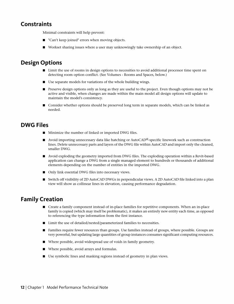
■ Model designs selectively. Objects only viewed from certain points need only be modeled to appearcorrect in those selected views. The following illustrations show two families, both designed to representthe same toilet in plan:
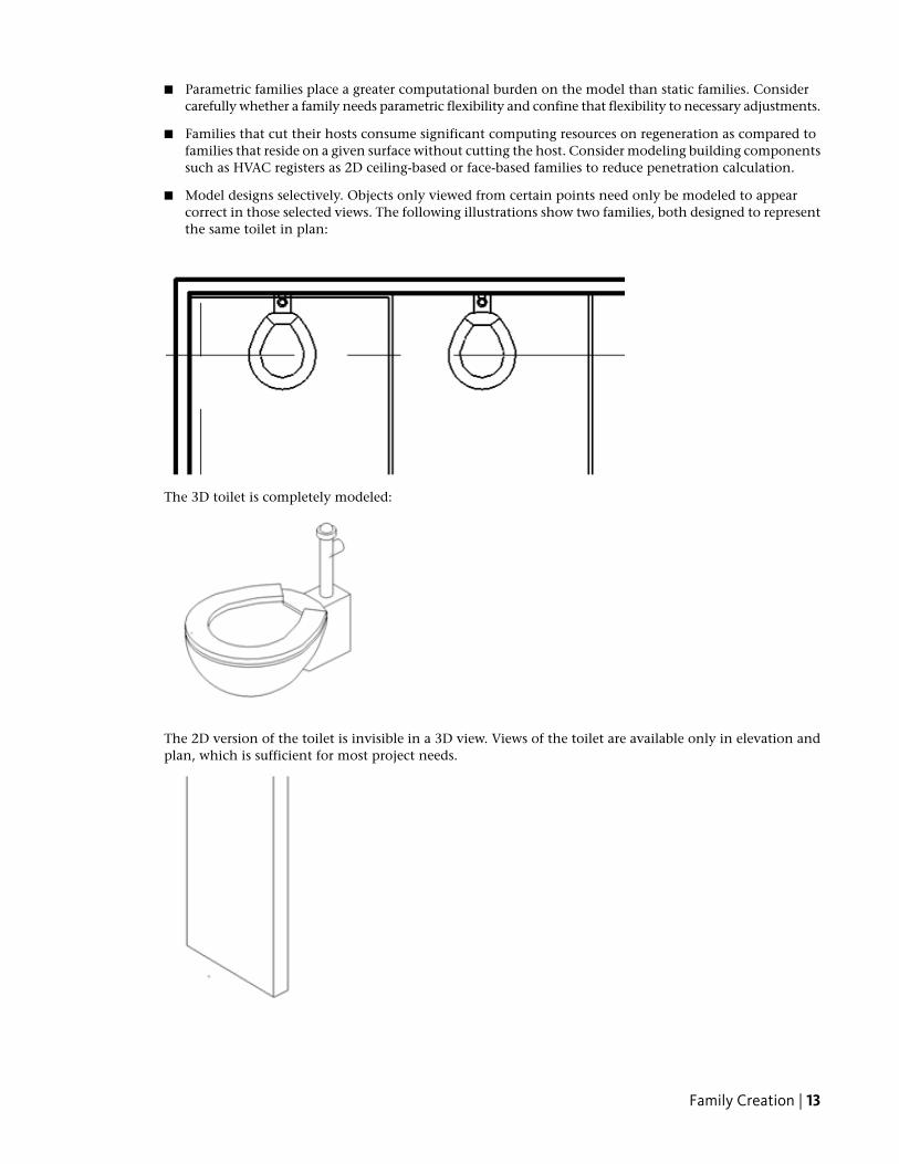
The 3D toilet is completely modeled:
The 2D version of the toilet is invisible in a 3D view. Views of the toilet are available only in elevation andplan, which is sufficient for most project needs.
Family Creation | 13
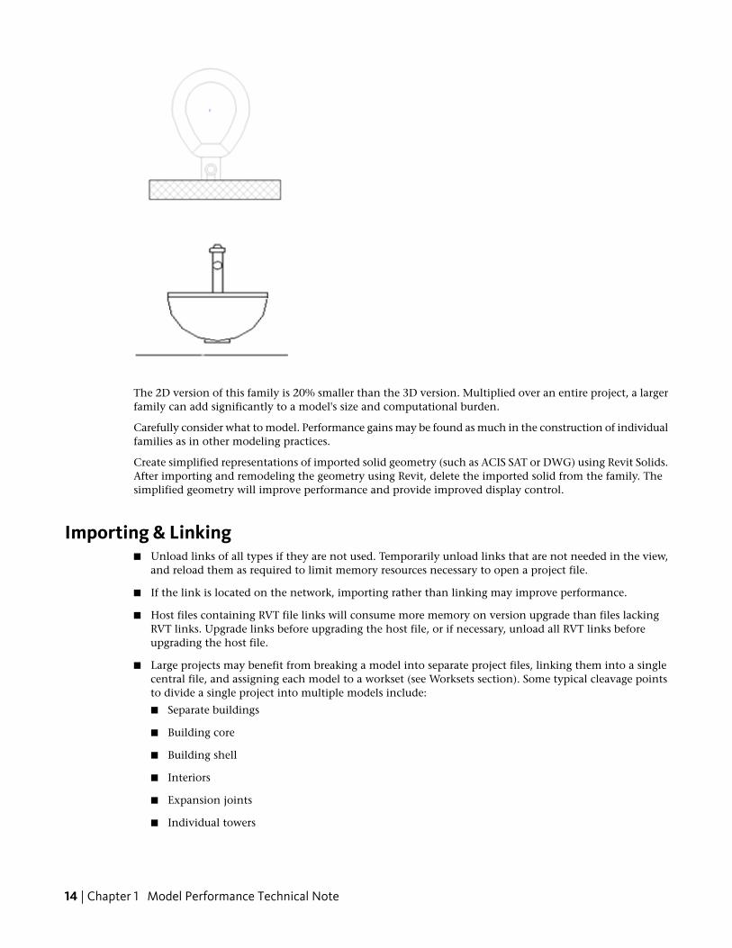
The 2D version of this family is 20% smaller than the 3D version. Multiplied over an entire project, a largerfamily can add significantly to a model's size and computational burden.
Carefully consider what to model. Performance gains may be found as much in the construction of individualfamilies as in other modeling practices.
Create simplified representations of imported solid geometry (such as ACIS SAT or DWG) using Revit Solids.After importing and remodeling the geometry using Revit, delete the imported solid from the family. Thesimplified geometry will improve performance and provide improved display control.
Importing & Linking■ Unload links of all types if they are not used. Temporarily unload links that are not needed in the view,
and reload them as required to limit memory resources necessary to open a project file.
■ If the link is located on the network, importing rather than linking may improve performance.
■ Host files containing RVT file links will consume more memory on version upgrade than files lackingRVT links. Upgrade links before upgrading the host file, or if necessary, unload all RVT links beforeupgrading the host file.
■ Large projects may benefit from breaking a model into separate project files, linking them into a singlecentral file, and assigning each model to a workset (see Worksets section). Some typical cleavage pointsto divide a single project into multiple models include:
■ Separate buildings
■ Building core
■ Building shell
■ Interiors
■ Expansion joints
■ Individual towers
14 | Chapter 1 Model Performance Technical Note
■ Parking structure(s)
■ Files may be linked, but not imported, using Shared Coordinates. Files may be imported using ProjectCoordinates only.
Modeling Economically■ Minimize geometric detail that will be invisible at the chosen output scale. The necessary level of detail
in a given model can often be conveyed to a team in terms of a commonly understood drawing scale,such as "Provide detail to a ¼" level of detail" or some other commonly employed measure of scale. Asmuch as possible, leverage the project team's understanding of typical 2D drawing conventions to investthe correct level of complexity into the model.
■ Until wall, roof, window, and door types are determined, use the generic versions of these elements,which incorporate less geometry. Unless material use or other types of analysis will be applied to themodel, consider that a generic wall may be sufficient for some projects or project areas.
■ Consistent customer practice is to break up a large model into multiple files of about 160 MB each for32-bit Revit, or 200 MB for 64-bit Revit, then link together the resulting project files. Such a procedurewill work best if the user can work on one file while the other links are unloaded for a majority of thetime. Engineering consumers of architectural models may have to maintain one or more constantlyloaded links, which may affect model size estimation and thresholds for those disciplines.
■ When creating detail views, model hatches with filled regions rather than lines.
■ Limit joined geometry to necessities.
■ Remove unneeded area schemes.
■ Avoid maintaining unnecessary groups. Delete unused groups from the project browser.
■ Purge unused objects. Because purged objects cannot be recovered, you may wish to make a backup ofthe project before purging.
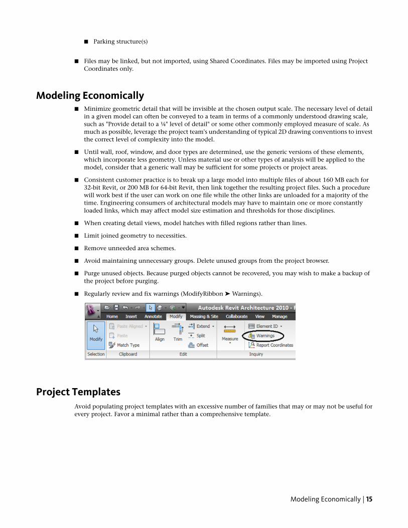
■ Regularly review and fix warnings (ModifyRibbon ➤ Warnings).
Project TemplatesAvoid populating project templates with an excessive number of families that may or may not be useful forevery project. Favor a minimal rather than a comprehensive template.
Modeling Economically | 15
Railings■ Avoid use of railings for extensive fences or separation systems, or at the very least limit the visibility of
these elements. There is no warning offered by Revit-based applications, but performance is impactedbecause of the number of lines required to generate each railing element.
■ If a lengthy railing element is desired, consider modeling a simplified railing representation, relying onrailing details to fully describe the design.
Raster Images■ Remove unneeded raster images and renderings. Raster images represent a performance and file size cost
that should be minimized.
■ Monochrome raster images are smaller than color images. Save black and white raster images as 1 bit perpixel format instead of JPG or TIF. MS Paint refers to this format as Monochrome Bitmap.
■ Large raster images such as logos scaled down to fit into title blocks will still retain the original file size.Consider creating a smaller, simplified image for import into a Revit-based application.
StairsLike railings, stairs are complex elements, but may not be easily simplified. Confine stair visibility to essentialviews.
Upgrading Linked Projects to a New Version of Revit■ Temporarily rename all central files. Renamed central files will fail to locate any Revit models linked to
the renamed central, and Revit will avoid temporarily upgrading the links.
■ After you have upgraded each central file, use the Save As command to return each to its original name.
■ Upgrade each central file's linked files. The upgraded central files will once again find the upgraded linkedfile.
Views■ Before closing a file, keep only a simple drafting view open to accelerate saving and subsequent opening
of the file.
■ Minimize view depth where possible in elevation, plan, and section views.
■ Consider back clipping views to reduce the quantity of geometry maintained in a view. Right-click inviews to select View Properties ➤ Far Clip Offset, and set the distance from the view camera to the desiredview depth.
■ Use section boxes to limit visible geometry when working in a 3D view.
■ Minimize view quantity to help reduce model size. To optimize static models to be linked into activemodels (for instance, in the case of an existing contextual building model adjoined to a model of newconstruction) delete as many views as possible from the static model to be linked.
■ Use the Wireframe or Shading display modes when working in a linked file environment. Wireframeand Shading modes can be 3 times faster than the Hidden Line or Shading with Edges modes.
16 | Chapter 1 Model Performance Technical Note
■ Avoid hiding large quantities of individual elements in views.
■ Using the Paste Aligned command to paste into closed views will open and close the target views. Whenrepeating such an operation several times, performance will be improved by opening all the target viewsbefore beginning the sequence of paste operations.
■ Zoom in to speed up drawing and snapping.
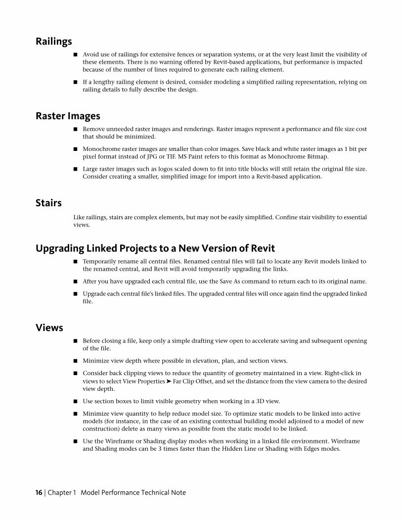
■ If you have a very dense view, and snap lines appear to be shooting off in all directions, click Managetab > Settings panel > Snaps, and in the Snaps dialog, clear the Snap to Remote Objects option.
■ Close unnecessary windows. When you are working in a 3D view, most of the file is placed into RAM.It is also recommended that these views should be closed when saving to central, since the Revit-basedapplications will regenerate this complex view as part of the save process.
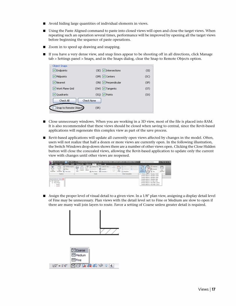
■ Revit-based applications will update all currently open views affected by changes in the model. Often,users will not realize that half a dozen or more views are currently open. In the following illustration,the Switch Windows drop-down shows there are a number of other views open. Clicking the Close Hiddenbutton will close the concealed views, allowing the Revit-based application to update only the currentview with changes until other views are reopened.
■ Assign the proper level of visual detail to a given view. In a 1/8" plan view, assigning a display detail levelof Fine may be unnecessary. Plan views with the detail level set to Fine or Medium are slow to open ifthere are many wall join layers to route. Favor a setting of Coarse unless greater detail is required.
Views | 17
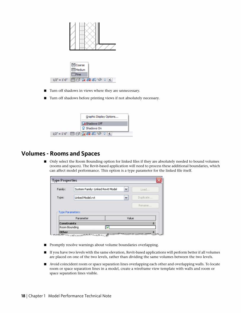
■ Turn off shadows in views where they are unnecessary.
■ Turn off shadows before printing views if not absolutely necessary.
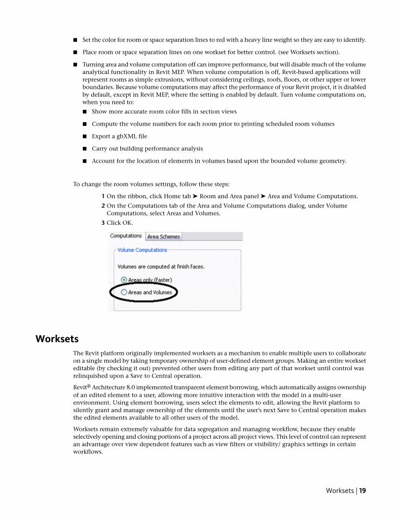
Volumes - Rooms and Spaces■ Only select the Room Bounding option for linked files if they are absolutely needed to bound volumes
(rooms and spaces). The Revit-based application will need to process these additional boundaries, whichcan affect model performance. This option is a type parameter for the linked file itself.
■ Promptly resolve warnings about volume boundaries overlapping.
■ If you have two levels with the same elevation, Revit-based applications will perform better if all volumesare placed on one of the two levels, rather than dividing the same volumes between the two levels.
■ Avoid coincident room or space separation lines overlapping each other and overlapping walls. To locateroom or space separation lines in a model, create a wireframe view template with walls and room orspace separation lines visible.
18 | Chapter 1 Model Performance Technical Note
■ Set the color for room or space separation lines to red with a heavy line weight so they are easy to identify.
■ Place room or space separation lines on one workset for better control. (see Worksets section).
■ Turning area and volume computation off can improve performance, but will disable much of the volumeanalytical functionality in Revit MEP. When volume computation is off, Revit-based applications willrepresent rooms as simple extrusions, without considering ceilings, roofs, floors, or other upper or lowerboundaries. Because volume computations may affect the performance of your Revit project, it is disabledby default, except in Revit MEP, where the setting is enabled by default. Turn volume computations on,when you need to:
■ Show more accurate room color fills in section views
■ Compute the volume numbers for each room prior to printing scheduled room volumes
■ Export a gbXML file
■ Carry out building performance analysis
■ Account for the location of elements in volumes based upon the bounded volume geometry.
To change the room volumes settings, follow these steps:
1 On the ribbon, click Home tab ➤ Room and Area panel ➤ Area and Volume Computations.
2 On the Computations tab of the Area and Volume Computations dialog, under VolumeComputations, select Areas and Volumes.
3 Click OK.
WorksetsThe Revit platform originally implemented worksets as a mechanism to enable multiple users to collaborateon a single model by taking temporary ownership of user-defined element groups. Making an entire workseteditable (by checking it out) prevented other users from editing any part of that workset until control wasrelinquished upon a Save to Central operation.
Revit® Architecture 8.0 implemented transparent element borrowing, which automatically assigns ownershipof an edited element to a user, allowing more intuitive interaction with the model in a multi-userenvironment. Using element borrowing, users select the elements to edit, allowing the Revit platform tosilently grant and manage ownership of the elements until the user's next Save to Central operation makesthe edited elements available to all other users of the model.
Worksets remain extremely valuable for data segregation and managing workflow, because they enableselectively opening and closing portions of a project across all project views. This level of control can representan advantage over view dependent features such as view filters or visibility/ graphics settings in certainworkflows.
Worksets | 19
While the capability to check out a workset remains valuable under certain circumstances outlined below,in general the best practice is to use element borrowing rather than checking out entire worksets. The Revitplatform team recommends that worksets should be employed most often to segregate conceptual areas ofa project, such as:
■ Separate buildings
■ Grid and levels
■ Building core
■ Building shell
■ Furniture and equipment spanning multiple categories
■ Spatially identifiable areas of a single building (such as wings)
■ Linked RVT and DWG files
■ Room or space separation lines (see Volumes - Rooms and Spaces section)
More workset information:
■ Checking out a workset may occasionally be of use if certain model elements, such as the building gridor linked files, need to be protected from accidental change. In that event, BIM managers or team leaderswill sometimes check out a workset containing project elements that should not be casually edited orrelocated.
■ Worksets can help manage element visibility to reduce visual clutter during editing, as well as the Revitplatform's use of memory. Closing currently unneeded worksets can release allocated RAM for the Revitplatform's use in memory-intensive tasks such as printing and exporting.Although closed worksets will not appear in views, any elements within them will still be updated duringmodel regeneration if they are impacted by changes made in open worksets, thus maintaining datacoordination across the model.
NOTE Upgrading models to the current version of the Revit-based application will force every workset to open,and will therefore not benefit from selective workset closure before file upgrade.
■ Use selective workset opening when accessing a workshared project file.
■ Close worksets not required for a given editing session.
■ When creating a workset, leave the Visible by default in all views option selected. Clearing this optioncan render the workset completely invisible and problematic in multi-discipline workflows where featurevisibility can be of paramount importance.
Worksharing■ Any large project requires constant team coordination. Most customers have realized many benefits by
providing teams with instant messaging (IM) software to help coordinate model editing and savingbetween geographically dispersed teams.
■ When making significant changes in a project (moving a level or major geometry changes), it isrecommended that you perform the operation when no other users are working on the file and all otherusers have relinquished all elements. Once the changes are saved to central, have all users make newlocal files.
■ Save to Central operations can be accelerated by a preceding Reload Latest command.
20 | Chapter 1 Model Performance Technical Note
■ When a project has been edited by other users for a day or more, it may be faster to create a new localfrom the central model rather than relying on the Reload Latest command to update the individual localmodel a day or more behind the remainder of the team.
■ Try to keep project team workstation specifications equivalent. A dramatically weaker machine specificationused by a single team member can reduce overall project performance.
■ Revit-based applications save only one local model at a time to the central file. As deadlines approachand the frequency of saving to central increases, use the Worksharing Monitor feature to coordinate Saveto Central commands across the team. Alternatively, team members could stagger their regular saves tocentral by either communicating an intention to save to central to the team or by assigning a standardsaving time to each team member; for example, at ten or fifteen minutes after the hour.
■ When attempts to save to central collide, Revit-based applications notify you that another user is currentlysaving to central. Cancelling the Save to Central operation will prevent queuing the save request, allowingthe user to continue to edit the local file before another Save to Central command.
■ Because the Revit platform attempts to update all open views before saving, both local saves and savingto central will increase in performance if a simple view, such as a drafting view, is the only view openwhen the save operation begins.
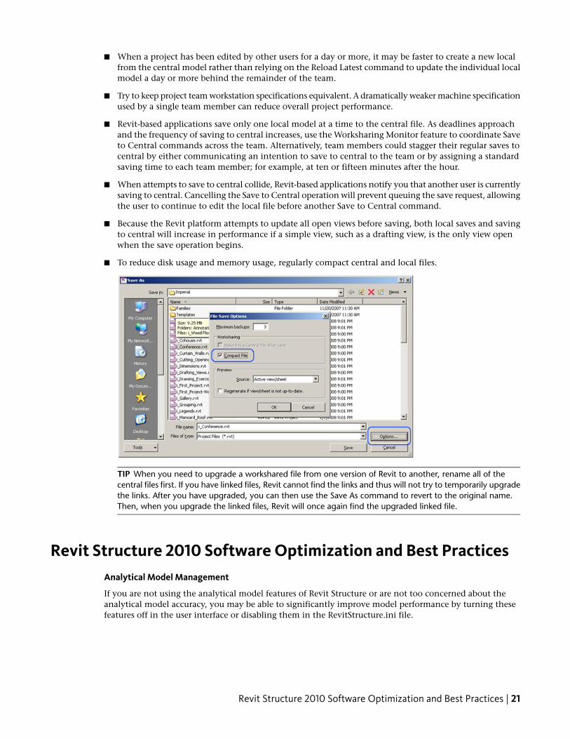
■ To reduce disk usage and memory usage, regularly compact central and local files.
TIP When you need to upgrade a workshared file from one version of Revit to another, rename all of thecentral files first. If you have linked files, Revit cannot find the links and thus will not try to temporarily upgradethe links. After you have upgraded, you can then use the Save As command to revert to the original name.Then, when you upgrade the linked files, Revit will once again find the upgraded linked file.
Revit Structure 2010 Software Optimization and Best PracticesAnalytical Model Management
If you are not using the analytical model features of Revit Structure or are not too concerned about theanalytical model accuracy, you may be able to significantly improve model performance by turning thesefeatures off in the user interface or disabling them in the RevitStructure.ini file.
Revit Structure 2010 Software Optimization and Best Practices | 21
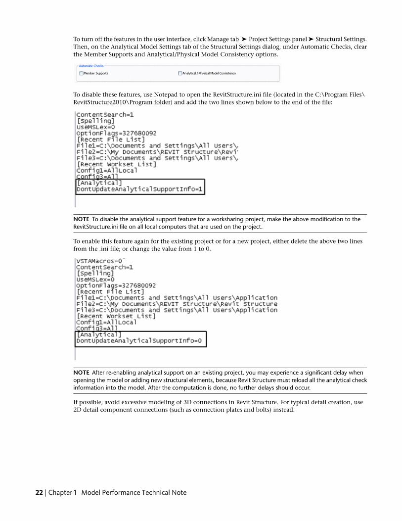
To turn off the features in the user interface, click Manage tab ➤ Project Settings panel ➤ Structural Settings.Then, on the Analytical Model Settings tab of the Structural Settings dialog, under Automatic Checks, clearthe Member Supports and Analytical/Physical Model Consistency options.
To disable these features, use Notepad to open the RevitStructure.ini file (located in the C:\Program Files\RevitStructure2010\Program folder) and add the two lines shown below to the end of the file:
NOTE To disable the analytical support feature for a worksharing project, make the above modification to theRevitStructure.ini file on all local computers that are used on the project.
To enable this feature again for the existing project or for a new project, either delete the above two linesfrom the .ini file; or change the value from 1 to 0.
NOTE After re-enabling analytical support on an existing project, you may experience a significant delay whenopening the model or adding new structural elements, because Revit Structure must reload all the analytical checkinformation into the model. After the computation is done, no further delays should occur.
If possible, avoid excessive modeling of 3D connections in Revit Structure. For typical detail creation, use2D detail component connections (such as connection plates and bolts) instead.
22 | Chapter 1 Model Performance Technical Note
Revit MEP 2010 Software Optimization and Best PracticesView Performance
The Model Graphics Style settings have the largest impact on performance for view manipulation operations(scroll, pan, and zoom). Due to the requirement to dynamically generate gaps and hidden lines whenelements overlap in the view, the Hidden Line style requires the most processing and thus results in anoticeable performance impact in views with many visible elements. The following best practices will helpto mitigate this performance impact and streamline project workflows.
Modeling and Sheet Views
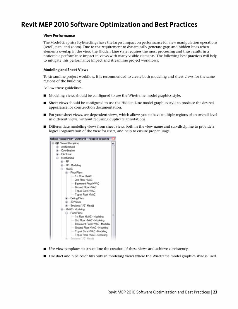
To streamline project workflow, it is recommended to create both modeling and sheet views for the sameregions of the building.
Follow these guidelines:
■ Modeling views should be configured to use the Wireframe model graphics style.
■ Sheet views should be configured to use the Hidden Line model graphics style to produce the desiredappearance for construction documentation.
■ For your sheet views, use dependent views, which allows you to have multiple regions of an overall levelin different views, without requiring duplicate annotations.
■ Differentiate modeling views from sheet views both in the view name and sub-discipline to provide alogical organization of the view for users, and help to ensure proper usage.
■ Use view templates to streamline the creation of these views and achieve consistency.
■ Use duct and pipe color fills only in modeling views where the Wireframe model graphics style is used.
Revit MEP 2010 Software Optimization and Best Practices | 23
Optimizing Hidden Line Performance
Performance in views with the Hidden Line model graphics style enabled is directly related to the numberof faces displayed in the view. Although elements display as 2D lines in a Revit view, in the model they are3D objects made up of faces. The faces are processed by the Revit graphics system and display in the viewas 2D lines. Use the following best practices to optimize the performance of views with the Hidden Linemodel graphics style enabled.
■ Avoid using the Fine detail level when working in mechanical views unless necessary, as multi-linerepresentations slow performance. Displaying pipes as 1-line at Medium detail level is usually sufficientwhen working with HVAC systems.
■ If using complex 3D components in your building service designs, turn off the visibility of the complex3D geometry in your sheet views. In place of the complex 3D geometry, use model lines that convey theoverall component shape in the family definition. Make those model lines visible at the detail leveldefined in your sheet views.
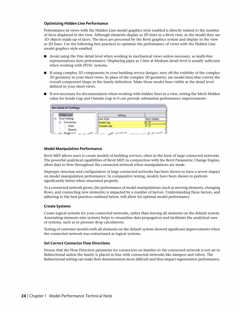
■ If not necessary for documentation when working with hidden lines in a view, setting the Mech Hiddenvalue for Inside Gap and Outside Gap to 0 can provide substantial performance improvements.
Model Manipulation Performance
Revit MEP allows users to create models of building services, often in the form of large connected networks.The powerful analytical capabilities of Revit MEP, in conjunction with the Revit Parametric Change Engine,allow data to flow throughout the connected network when manipulations are made.
Improper structure and configuration of large connected networks has been shown to have a severe impacton model manipulation performance. In comparative testing, models have been shown to performsignificantly better when structured properly.
As a connected network grows, the performance of model manipulations (such as moving elements, changingflows, and connecting new elements) is impacted by a number of factors. Understanding these factors, andadhering to the best practices outlined below, will allow for optimal model performance.
Create Systems
Create logical systems for your connected networks, rather than leaving all elements on the default system.Associating elements into systems helps to streamline data propagation and facilitates the analytical usesof systems, such as in pressure drop calculations.
Testing of customer models with all elements on the default system showed significant improvements whenthe connected network was restructured as logical systems.
Set Correct Connector Flow Directions
Ensure that the Flow Direction parameter for connectors on families in the connected network is not set toBidirectional unless the family is placed in-line with connected networks like dampers and valves. TheBidirectional setting can make flow determination more difficult and thus impact regeneration performance.
24 | Chapter 1 Model Performance Technical Note
Multiple Files
While maintaining the entire design for a building service in one well connected model allows for full datapropagation, the size of the connected network is directly related to its manipulation performance. Testinghas shown a linear decrease in manipulation performance as a connected network size grows. The rate ofdecrease is directly related to the topics mentioned in this section.
Because the performance of connected networks decreases with larger size, the benefits of data propagationand connectivity may be outweighed by the need for better model manipulation performance.
For large, complex buildings, the aforementioned best practices may still not provide optimum modelmanipulation performance. In these cases, the model should be built across multiple Revit project files.
There are two fundamental ways to structure the MEP project files: by MEP discipline or by region of thebuilding. Both of these approaches have their benefits and drawbacks, and ultimately it is the choice of theBIM/CAD manager.
By Discipline
■ This strategy creates separate project files for each MEP discipline; that is, separate Mechanical, Electrical,Plumbing, and Fire Protection files.
By Region
■ This strategy creates separate project files for different regions of the building, keeping all disciplines ineach file.
In order to achieve optimal coordination between the MEP disciplines, each discipline must be within thesame Revit project file. This organization allows disciplines to connect to each other's elements directly, likeelectrical connections or drain connections on mechanical equipment. Additionally, product team testinghas shown that separate connected networks do not have a significant impact on each other; a duct networkdoes not have a significant impact on model manipulation of a plumbing network in the same project file.
Based on these considerations, it may be helpful to structure large projects by region of the building.
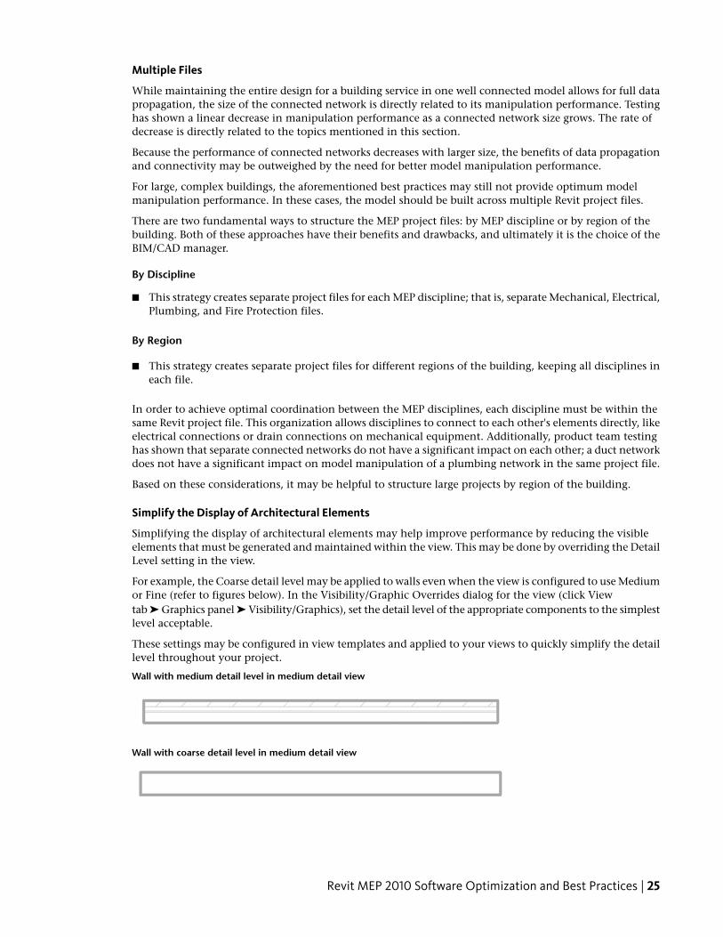
Simplify the Display of Architectural Elements
Simplifying the display of architectural elements may help improve performance by reducing the visibleelements that must be generated and maintained within the view. This may be done by overriding the DetailLevel setting in the view.
For example, the Coarse detail level may be applied to walls even when the view is configured to use Mediumor Fine (refer to figures below). In the Visibility/Graphic Overrides dialog for the view (click Viewtab ➤ Graphics panel ➤ Visibility/Graphics), set the detail level of the appropriate components to the simplestlevel acceptable.
These settings may be configured in view templates and applied to your views to quickly simplify the detaillevel throughout your project.
Wall with medium detail level in medium detail view
Wall with coarse detail level in medium detail view
Revit MEP 2010 Software Optimization and Best Practices | 25
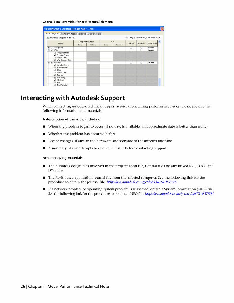
Coarse detail overrides for architectural elements
Interacting with Autodesk SupportWhen contacting Autodesk technical support services concerning performance issues, please provide thefollowing information and materials:
A description of the issue, including:
■ When the problem began to occur (if no date is available, an approximate date is better than none)
■ Whether the problem has occurred before
■ Recent changes, if any, to the hardware and software of the affected machine
■ A summary of any attempts to resolve the issue before contacting support
Accompanying materials:
■ The Autodesk design files involved in the project: Local file, Central file and any linked RVT, DWG andDWF files
■ The Revit-based application journal file from the affected computer. See the following link for theprocedure to obtain the journal file: http://usa.autodesk.com/getdoc/id=TS1067426
■ If a network problem or operating system problem is suspected, obtain a System Information (NFO) file.See the following link for the procedure to obtain an NFO file: http://usa.autodesk.com/getdoc/id=TS1057804
26 | Chapter 1 Model Performance Technical Note