Embed Size (px)
Citation preview
1 of 60
``MODEL ROCKETRY FUNDAMENTALS
Unit 1—Plastic Fins OnlyUnit 2—Balsa/Basswood Fins Only*Each unit requires a separate supplemental booklet for plastic or balsa/basswood fin rocket construction.
Table of Contents
Introduction
Rocketry—Hobby, Craft, Sport and a Profession
Brief History of Early to Modern Rocketry
Model Rocketry Profile
History of Model Rocketry
NAR Model Rocketry Safety Code
Types of Model Rockets
Science Principles of Rocketry
Newton’s Three Laws of Motion
Law of Inertia –1ST Law
Law of Momentum --2nd Law
Law of Reaction –3 rd Law
Anatomy of a Rocket
*Systematic Process of Model Rocket Construction
Unit 1 Supplemental Booklet –Plastic Fin Model Rocket Construction
Unit 2 Supplement Booklet –Balsa and Basswood Model Rocket Construction
Elements and Principles of Rocket Flight
Black Powder Rocket Motors
Parts of a Solid Fuel Rocket Motor
How a Motor Performs in Flight
Motor Classification
2 of 60
Rocket Stability
Understanding Stability
Center of Gravity (CG)
Center of Pressure (CP)
Other Factors that Affect Stability
Types of Recovery Systems
Launch Systems and Field Operations
Parts of a Model Rocket Launch System
Selection and Preparation of a Launch Field
Flight Operation and Safety Check Procedures
Preparing Your Rocket for Flight
Recovery Wadding
Experiment with Parachutes
Preparation of a Parachute and Streamer Recovery System
Motor Installation
Installation of an Igniter
Placing the Rocket to the Launch Pad
Launching Your Rocket
Launch Procedures
Ignition Misfires
Rocket Recovery
Checklist
Launch Setup and Range Equipment Checklist
Flight Preparations Checklist
Rocket Flight Log Sheet
3 of 60
Adventure Questions
Glossary of Terms
Educational and Rocket Resources
*Unit 1—Supplemental Booklet –Model Rocket Construction with Plastic Fins
Select a Rocket Kit and Get Organized
Where to Look for Rocket Kits
Selecting your Rocket Kit
Find an Appropriate Work Area
Practice Patience
Read Your Kit Instructions Entirely Before You Begin
Well-Equipped Rocketry Tool and Range Box
Construction Supplies and Tools for Plastic Model Rocket Kits
Optional Build Equipment and Supplies
Range Tools and Supplies
Plastic Model Rocket Construction Techniques
Preparation of all Plastic Parts
Gluing Plastic Parts
Nosecone Preparation
Airframe (Body Tube) Preparation, if needed
About Shock Cords
Methods of Attaching the Shock Cord
Motor Mount Assembly
Couplers and Payload Sections
Learning about Fins
4 of 60
Attaching the Fins or Fin Can Unit
Attaching the Launch Lug, if needed
Painting Techniques
Finishing Techniques
Rocket Log Sheet for Unit 1
Unit 2 Supplemental Booklet ---Model Rocket Construction with Balsa and Basswood Fins
Select a Rocket Kit and Get Organized
Where to Look for Rocket Kits
Selecting Your Rocket Kit
Inventory Your Rocket Kit
Find an Appropriate Work Area
Practice Patience
Read Your Kit Instructions Entirely Before You Begin
Well-Equipped Rocketry Tool and Range Box
Construction Supplies and Tools for Balsa and Basswood Fins
Optional Build Equipment and Supplies
Range Box Tools and Supplies
Balsa and Basswood Model Rocket Construction Techniques
Preparation of All Plastic Parts
Gluing Plastic Parts
Nosecone Preparation
Airframe (Body Tube) Preparation
About Shock Cords
Methods of Attaching the Shock Cord
Motor Mount Assembly
5 of 60
Couplers and Payload Sections
Learning about Fins
Balsa and Basswood Fin Preparation
Marking the Airframe for Fins and Launch Lug
Aligning, Attaching and Filleting the Fins
Painting Techniques
Finishing Techniques
Rocket Log Sheets for Unit 2
INTRODUCTION
Congratulations! By taking this project, you are taking steps to becoming the next astronaut or scientist who will change space travel in the future.
Model Rocketry Fundamentals is for the 4-H member who has little to no experience in building or launching model rockets. As a 4-H member, leader, or parent, you will learn about the history of rocketry (brief), principles of rocketry, systematic instruction for plastic fin rocketry construction (Unit 1), balsa/basswood fin rocketry construction (Unit 2), and launching principles.
A member may take both Unit 1 and Unit 2, but will need to exhibit in the highest unit completed.
ROCKETRY—HOBBY, CRAFT, SPORT AND A PROFESSION
Hobby—Rocketry is a hobby simply for the enjoyment of building rockets and the thrill of launching. Hobbyists not only enjoy building rockets, but they love adding to their fleet of rockets and searching for vintage rockets. There are three main categories in model rocketry: Low Power Rocketry (LPR) or Model Rocketry, High Power Rocketry (HPR), and Amateur Rocketry (includes Experimental or Research Rocketry).
Craft—Rocketry is a craft where members learn about external and internal parts of a rocket and the basic characteristics of a rocket. Members also learn about Newton’s Three Laws of Motion, center of gravity, center of pressure, rocket stability and flight of a rocket. Members develop rocket construction techniques and skills, and discover finishing techniques for a show quality rocket.
Sport—Rocketry is a sport involving launches opens to the public, which are typically supported by local National Association of Rocketry (NAR) or Tripoli chartered section clubs. Rocketry clubs often support schools and youth groups in educational programs involving the science of rocketry. Chartered section clubs also hold rocket contests for fun and prizes, e.g. Egg Loft, Glide Duration, Hang Duration, Streamer or Parachute Spot Landing events. As members advance in rocketry and rocketry skills, they become eligible to participate in events on a national level and compete for scholarship opportunities.
6 of 60
Profession—Rocketry is also a profession involving private, commercial and governmental jobs and opportunities. A variety of careers can be centered on rocketry, such as mechanical, electrical and software engineers; scientists; mathematicians; physicists; chemists; technicians; and astronauts.
BRIEF HISTORY OF ROCKETRY
Modern rocketry is the culmination of over 2,000 years of human imagination, experimentation, invention, warfare and scientific discovery. As early as the 3rd century B.C., Archytas, a Greek philosopher, mathematician and astronomer, created a device propelled by a jet of steam or compressed air, the first known recording of a device that used thrust for motion. Around 50 A.D., Greek mathematician, physicist, and engineer Hero of Alexandria invented a rocket-like reaction steam motor, called an “aeolipile,” that utilized the fundamental principles of rocket and jet propulsion. Rocket technology was discovered in the early 13th century when Chinese technicians noticed that their fireworks, made from rudimentary gunpowder in bamboo tubes, would sometimes skip or fly through the air, propelled by gas-produced thrust. From that time on until the advent of modern-era space travel, rocket innovations were used primarily for military purposes, aided by basic and applied scientific research in astronomy, physics, math and engineering.
In the 17 century, Italian astronomer and physicist Galileo Galilei discovered “inertia,” one of the most important contributions to the science of motion. Building on Galileo’s work, Sir Issac Newton, also during the 17th century, published his Three Laws of Motion, which form the scientific basis for all of modern rocket science. Scientists, theorists and engineers applied these principles in their designs and inventions for the next 300 years. British Colonel William Congreve, circa 1800, invented case-shot rockets, incendiary rockets, and launching rockets from ships. During the War of 1812, the British launched hundreds of rockets against Fort McHenry in Baltimore, Maryland. Inspired by American resistance, Francis Scott Key wrote “The Star Spangled Banner,” the poem that became our National Anthem, containing the lines “and the Rockets’ red glare, the Bombs bursting in air.”
In the last one hundred fifty years, three individuals contributed greatly to science model rocketry. Konstantin Tsiolkovsky (the “Father of Modern Astronautics”) was a Russian schoolteacher renowned for his vision of space exploration and his research into the possibilities of earth satellites and space stations. American college professor Robert Goddard (the “Father of Modern Rocketry”) created and launched the first liquid propellant rocket motor in 1926, and received patents for combustion chambers, exhaust nozzles, propellant feed systems and multi-stage rockets. Hermann Oberth of Germany (the “Father of Space Flight”), is acclaimed for his numerous publications and writings about rocket travel into outer space that resulted in the development of many small rocket societies around the world.
German rocket physicist and astronautics engineer Wernher von Braun and colleagues built the World War II-era V2 rocket, which evolved into the intercontinental ballistic missile (ICBM) system, the forerunner of the manned space program. Von Braun and other German scientists secretly entered the U.S. after World War II to work for the U.S. Army. Von Braun became a naturalized U.S. citizen in 1955,

7 of 60
eventually joined NASA, and was the chief architect of the Saturn V launch vehicle, the vehicle that propelled the Apollo spacecraft to the Moon.
After World War II, the United States and the Soviet Union competed to be the first nation into space. The Soviet Union sent the first manmade objects into space in 1957 with its satellites’ Sputnik I and Sputnik II. The U.S. countered with the launching of its first satellite Explorer I in 1958. Russian Cosmonaut Yuri Gagarin became the first human being to orbit the earth in 1961, followed by American Alan Shepherd’s suborbital flight. The rocket that carried the Mercury space capsule with Shepherd into space was not powerful enough to reach earth’s orbit. In 1962, American Astronaut John Glenn would be the first American to orbit the earth, and in 1969, American Astronauts Neil Armstrong and Buzz Aldrin would be the first human beings to land on the moon.
From the early 1960s to present day, the United States and other countries have made tremendous advances in both manned and unmanned space technology and travel. Titan rockets were used to launch the Gemini missions, and the Titan’s successors propelled satellites into orbit and launched unmanned spacecraft to other planets and beyond, as witnessed by the Viking missions to Mars and the Voyager missions into deep space. Smaller rockets such as the Canadian Black Brant, the European Space Agency’s Ariane, and the American Atlas and Pegasus carry commercial, scientific and military satellites and payloads into space. The Space Shuttle flew its first mission in 1981. A four-part vehicle transportation system, the Shuttle program’s major purpose was to build and supply the International Space Station (ISS) with crews and cargo. The ISS, which is supported by 16 nations, points toward a peaceful future for the mission of rocket science and space exploration. (Recommend to see the movie “October Sky”)
MODEL ROCKETRY PROFILE
History of Model Rocketry
With the end of World War II, the sky no longer held “limits” for individual imaginations and reaching for the stars was no longer a dream but a possibility. Young rocket enthusiasts started designing and building their own “model” rockets and rocket motors—involving metallic airframes and the mixing of dangerous propellants—that was responsible for injuring and even killing numerous young scientific experimenters. A licensed pyrotechnics expert, Orville Carlisle and his brother Robert designed a model rocket and model rocket motors for Robert to use in his lectures on the principles of rocket-powered flight. G. Harry Stine, and engineer and author, wrote articles published in Popular Mechanics about young people attempting to make their own rocket motors with disastrous results. Upon reading those articles, the Carlisle’s realized their rocket motors could be marketed to provide a safer alternative for the hobby of model rocketry. The Carlisle brothers sent samples of their designs to Mr. Stine, resulting in Mr. Stine’s publication of the Handbook of Model Rocketry. Mr. Stine, who later became known as the “Father of Model Rocketry,” founded the National Association of Rocketry (NAR) shortly after the launch of Sputnik I in 1957 to promote model rocketry and safety within the hobby. Mr. Stine and Orville Carlisle also formed the first model rocket company, Model Missiles Incorporated, in Denver, Colorado. Orville Carlisle became the first member of NAR, and later served as a member of the

8 of 60
“Technical Committee on Pyrotechnics” of the National Fire Protection Agency (NFPA). NAR, in collaboration with NFPA, sets the standards, which governs all model rocketry enthusiasts today, the NAR Model Rocketry Safety Code.
Today, model rockets are constructed of much safer materials—such as cardboard, plastic, and balsa wood—and are fueled by single-use rocket motors manufactured by professional concerns. These rockets may be flown repeatedly simply by replacing the used motor with a fresh one. They typically contain a parachute, streamer, or other recovery device that allows them to land gently for later re-flight. The modeler need never mix, pack, or work with explosives or propellants.
For Adult and Volunteer Leaders:
Check out the 4-H website for information on governing agencies and model rocketry organizations and clubs at www.colorado4h.org
NAR Model Rocket Safety Code
1. Materials. I will use only lightweight, non-metal parts for the nose, body, and fins of my rocket. 2. Motors. I will use only certified, commercially made model rocket motors, and will not tamper
with these motors or use them for any purposes except those recommended by the manufacturer.
3. Ignition System. I will launch my rockets with an electrical launch system and electrical motor igniters. My launch system will have a safety interlock in series with the launch switch, and will use a launch switch that returns to the "off" position when released.
4. Misfires. If my rocket does not launch when I press the button of my electrical launch system, I will remove the launcher's safety interlock or disconnect its battery, and will wait 60 seconds after the last launch attempt before allowing anyone to approach the rocket.
5. Launch Safety. I will use a countdown before launch, and will ensure that everyone is paying attention and is a safe distance of at least 15 feet away when I launch rockets with D motors or smaller, and 30 feet when I launch larger rockets. If I am uncertain about the safety or stability of an untested rocket, I will check the stability before flight and will fly it only after warning spectators and clearing them away to a safe distance.
6. Launcher. I will launch my rocket from a launch rod, tower, or rail that is pointed to within 30 degrees of the vertical to ensure that the rocket flies nearly straight up, and I will use a blast deflector to prevent the motor's exhaust from hitting the ground. To prevent accidental eye injury, I will place launchers so that the end of the launch rod is above eye level or will cap the end of the rod when it is not in use.
7. Size. My model rocket will not weigh more than 1,500 grams (53 ounces) at liftoff and will not contain more than 125 grams (4.4 ounces) of propellant or 320 N-sec (71.9 pound-seconds) of total impulse.
8. Flight Safety. I will not launch my rocket at targets, into clouds, or near airplanes, and will not put any flammable or explosive payload in my rocket.

9 of 60
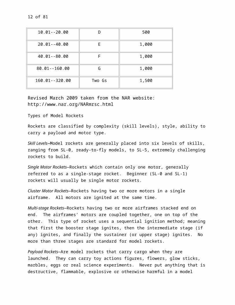
9. Launch Site. I will launch my rocket outdoors, in an open area at least as large as shown in the table below and in safe weather conditions with wind speeds no greater than 20 miles per hour. I will ensure that there is no dry grass close to the launch pad, and that the launch site does not present risk of grass fires.
10. Recovery System. I will use a recovery system such as a streamer or parachute in my rocket so that it returns safely and undamaged and can be flown again, and I will use only flame-resistant or fireproof recovery system wadding in my rocket.
11. Recovery Safety. I will not attempt to recover my rocket from power lines, tall trees, or other dangerous places.
A fire extinguisher and First Aid Kit should be available.
LAUNCH SITE DIMENSIONS
Installed Total Impulse (N-sec)
Equivalent Motor Type
Minimum Site Dimensions (ft.)
0.00--1.25 1/4A, 1/2A 50
1.26--2.50 A 100
2.51--5.00 B 200
5.01--10.00 C 400
10.01--20.00 D 500
20.01--40.00 E 1,000
40.01--80.00 F 1,000
80.01--160.00 G 1,000
160.01--320.00 Two Gs 1,500
Revised March 2009 taken from the NAR website: http://www.nar.org/NARmrsc.html
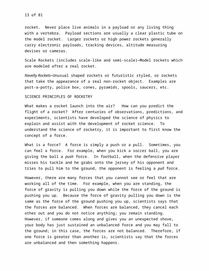
Types of Model Rockets
Rockets are classified by complexity (skill levels), style, ability to carry a payload and motor type.
Skill Levels—Model rockets are generally placed into six levels of skills, ranging from SL-0, ready-to-fly models, to SL-5, extremely challenging rockets to build.

10 of 60
Single Motor Rockets—Rockets which contain only one motor, generally referred to as a single-stage rocket. Beginner (SL-0 and SL-1) rockets will usually be single motor rockets.
Cluster Motor Rockets—Rockets having two or more motors in a single airframe. All motors are ignited at the same time.
Multi-stage Rockets—Rockets having two or more airframes stacked end on end. The airframes’ motors are coupled together, one on top of the other. This type of rocket uses a sequential ignition method; meaning that first the booster stage ignites, then the intermediate stage (if any) ignites, and finally the sustainer (or upper stage) ignites. No more than three stages are standard for model rockets.
Payload Rockets—Are model rockets that carry cargo when they are launched. They can carry toy actions figures, flowers, glow sticks, marbles, eggs or real science experiments. Never put anything that is destructive, flammable, explosive or otherwise harmful in a model rocket. Never place live animals in a payload or any living thing with a vertebra. Payload sections are usually a clear plastic tube on the model rocket. Larger rockets or high power rockets generally carry electronic payloads, tracking devices, altitude measuring devises or cameras.
Scale Rockets (includes scale-like and semi-scale)—Model rockets which are modeled after a real rocket.
Novelty Rockets—Unusual shaped rockets or futuristic styled, or rockets that take the appearance of a real non-rocket object. Examples are port-a-potty, police box, cones, pyramids, spools, saucers, etc.
SCIENCE PRINCIPLES OF ROCKETRY
What makes a rocket launch into the air? How can you predict the flight of a rocket? After centuries of observations, predictions, and experiments, scientists have developed the science of physics to explain and assist with the development of rocket science. To understand the science of rocketry, it is important to first know the concept of a force.
What is a force? A force is simply a push or a pull. Sometimes, you can feel a force. For example, when you kick a soccer ball, you are giving the ball a push force. In football, when the defensive player misses his tackle and he grabs onto the jersey of his opponent and tries to pull him to the ground, the opponent is feeling a pull force.
However, there are many forces that you cannot see or feel that are working all of the time. For example, when you are standing, the force of gravity is pulling you down while the force of the ground is pushing you up. Because the force of gravity pulling you down is the same as the force of the ground pushing you up, scientists says that the forces are balanced. When forces are balanced, they cancel each other out and you do not notice anything; you remain standing. However, if someone comes along and gives you an unexpected shove, your body has just sustained an unbalanced force and you may fall to the ground; in this case, the forces are not balanced. Therefore, if one force is greater than another is, scientists say that the forces are unbalanced and then something happens.

11 of 60
The ideas of Galileo and Isaac Newton explain how forces can make things move. These laws explain rocketry.
Galileo’s discovery of inertia is especially important for rocketry. Galileo rolled balls down ramps, across flat surfaces, and threw them around a room. He discovered that falling objects fall increasingly faster because gravity is pulling them to the ground. However, he noticed that objects rolling along a flat surface kept the same speed. Galileo called this concept inertia. Inertia describes why a spacecraft keeps moving forever in space at the same speed unless it uses its engine to speed up or slow down or until it bumps into something.
Explore Inertia Activity
Prep time: 20 seconds
Experiment time: 10 seconds
Fun factor: 4.5 stars out of 5 stars if you have not seen this trick before
Materials:
Mug
One playing card
Nickel or quarter
1. Place the mug upside down on a flat surface, preferably a table or a counter. 2. Place the playing card on top of the bottom of the mug so that the ends of the playing card stick
over the edge of the mug. 3. Place the coin on top of the card at the center of the mug.4. Using your thumb and forefinger, snap the card away from you. Be sure to snap level with the
card.5. Next time try it with the mug right side up. What happens?
What happened? The coin should slightly drop onto the bottom of the mug in the same position as before, in the center of the mug.
Why? This activity illustrates inertia. Before you snap the card, the force of gravity is pulling down on the coin and the force of the card is pushing up on the coin; the forces are balanced. When you snap the card away, the coin stays in the same relative position in the center of the mug because of inertia; the coin is at rest and remains at rest until a force is acted upon it. (The coin falls slightly onto the bottom of the mug because the force of gravity is no longer countered by the force of the card.)
12 of 60
You may have seen several different versions of this trick. In one version, a person pulls the tablecloth out from under a table setting of china dishes and crystal glasses. All of these different versions illustrate the concept of inertia!
Another example of unbalanced forces:
Straw activity
Prep time: 5 seconds
Experiment time: 5 seconds
Fun Factor: 5 out of 5 stars
Material: Drinking straw with paper wrapper on it
Procedure:
1. Carefully tear off one end of the paper wrapper on a drinking straw. Slide the paper wrapper about ½” away from the end, so that when you put your mouth on the drinking straw, the paper is not in your mouth.
2. Blow into the straw.
What happens? The paper wrapper on the drinking straw shoots off the straw.
Why? When air is blown into the straw with the paper wrapper, the paper wrapper moves away from you.
Isaac Newton used Galileo’s discovery of inertia to develop his first law of motion; in fact, this law is usually called the law of inertia. Newton’s first law says that an object at rest will remain at rest and an object in motion will remain in motion unless acted upon by an unbalanced force.
An object at rest will stay at rest until a force is exerted on it. This means that when you put your rocket on the launch pad, it will stay there until you launch the rocket. The surface of the launch pad pushes the rocket up while gravity pulls the rocket down. Because these forces are equal, the rocket remains on the launch pad. When an additional force is exerted on the rocket, the force from the motor lifts the rocket off the launch pad.
An object will keep moving in a straight line at a constant speed until a force acts on it. For example, if you kick a soccer ball, it will keep rolling. However, you know that the soccer ball will eventually stop rolling and Newton’s law explains why. The force from friction of the grass and the air acts on the soccer ball, slowing it down until the soccer ball eventually stops. However, in outer space, friction is small. In rocketry, Newton’s first law says that a space rocket will move in a straight line at the same speed until other forces change the flight path of the rocket. When you watch the movement of a puck on an air
13 of 60
hockey table, you are observing a system with almost no friction, similar to outer space. The puck keeps moving in a straight line until it bumps into the side of the table, hits the goal, or until a player hits the puck.
What causes friction? Tiny grooves and ridges on the surfaces of objects cause friction. Many times, you cannot even see these grooves and bumps. However, the grooves and ridges snag on each other, slowing down the object. The rougher the surface, the bigger the grooves and the ridges are, making it easier to snag and slow down the object.
Drag is a type of friction that occurs when objects move through liquids such as water or gases such as air. Drag slows down runners, swimmers, and racecars. That is why many swimmers in the Olympics wear specially designed swim suits to make the grooves and ridges in the swim suit fabric smaller, or in other words, to minimize the drag of a swimmer in the water; these specially designed swim suits can make a person swim a fraction of a second faster, enough to help that person win a race. Drag is also, why racecars have a more streamlined shape than a van.
Drag also affects model rockets. If the surface of your model rocket is not smooth, your rocket will not accelerate as much and will not soar as high as predicted with a certain rocket engine. Therefore, you might need to sand your rocket fins. When you participate in an advanced model rocketry project, you will have the opportunity to design your own rocket. In that project, you may want to design a streamlined rocket to minimize drag.
Newton’s second law describes what happens when a force acts on something. If the force acts on an object that is not moving (at rest) and the force is big enough, then the object will start moving (accelerating) in the direction of the force. If the object is moving, then the force can make the object move faster (accelerate), slow it down (decelerate), or change its direction.
Newton expressed these ideas in a simple mathematical equation:
F=ma
Force (f) = mass (m) multiplied by (X) acceleration (a).
According to his equation, if the object keeps the same mass, the bigger the force that is applied, the larger the acceleration will be. The more powerful rocket engine that you use to launch your rocket, the greater the acceleration of your model rocket.
However, Newton’s equation also says that if the force stays the same, a lighter object that has less mass will accelerate or decelerate faster than a heavier object with more mass. What does this mean? For example, if you are racing on a bicycle, it is easier to go faster on a lighter weight bicycle than on a
14 of 60
heavier one. Similarly, this law explains why it takes longer from a freight train to come to a stop than a car or a person on a bicycle; a freight train loaded down with coal is a much heavier object with much more mass.
Newton’s second law explains why there are different types of rocket engines for model rockets. A model rocket with less mass will have a greater acceleration than a rocket with more mass using the same type of rocket engine. Therefore, the acceleration of a model rocket depends upon the mass of the rocket and the force of the rocket engine. If you are attempting to launch a model rocket with more mass, you will need to use a more powerful engine to overcome the force of gravity.
By now, you have probably noticed that we have used the words mass and weight. Many people use weight and mass interchangeably, but that is not technically correct. So, what is the difference between mass and weight? For example, pretend that you weigh 100 pounds when you step onto a scale on Earth. However, if you step onto a scale on the moon you will weigh less than 17 pounds and on Jupiter, you will weigh a whopping 264 pounds. What happened? After all, you are the same person; the amount of material that you contain, called your mass, is the same. No matter whether you are standing on the Earth, on the moon, or on Jupiter, your mass remains the same. When you weigh yourself on Earth, the scale records your mass plus the force of Earth’s gravity, the number on the scale that you see is called your weight. However, the force of gravity on the moon is one-sixth the force of gravity on Earth; thus, you weigh much less on the moon than you do on Earth. In contrast, the force of gravity on Jupiter is 2.64 greater. Therefore, you weigh much more on Jupiter than you do on Earth. Thus, mass is the amount of material that an object contains and remains the same regardless of its location. In contrast, weight depends upon the force of gravity on an object’s mass; thus, an object’s weight will change depending upon its location.
Why is this important? Newton’s equation uses mass instead of weight. Thus, the equation says that the force necessary to move an object is the same on the Earth, the moon, Jupiter, or in space.
There is also a difference between acceleration and speed (velocity). Let us say that you are running at the pace of 9 miles per hour. After awhile, you get tired and start to slow down. Then as you are reaching the finish line, you see that your competitor is just in front of you. By speeding up or accelerating, you cross the finish line before your opponent and win the race! Thus, speed is how fast you are traveling. Acceleration describes any change in speed, whether it is positive or negative. A Decrease in speed is called deceleration.
Newton’s third law states that for every action, there is an equal and opposite reaction. This law explains why a rocket launches into space. When the rocket motor pushes gas downward (the action in Newton’s law), the gas pushes back on the rocket (the reaction in Newton’s law), pushing the rocket upward, and liftoff occurs.
Activities to explore Newton’s third law
15 of 60
Balloon activityPrep time: 30 seconds
Experiment time: 20 seconds
Fun Factor: 4.8 stars out of 5 stars
Material: balloons
Procedure: Blow up a balloon. Release.
What happens? The balloon “flies” around the room.
Why? When air is released from the balloon (the action in Newton’s third law), the balloon moves away (the reaction in Newton’s third law). Why doesn’t the balloon move straight forward? That is because the air is not released evenly from the balloon, causing the balloon to vibrate, and move unpredictably around the room.
Rocket balloons
Prep time: 3-5 minutes
Experiment time: 30 seconds
Fun factor: 3 stars out of 5 stars
This is a fun activity. However, it is a little more difficult than the previous activities because it is tricky to attach the balloon properly to the straw.
Materials:
Balloons Drinking straw Smooth string or fishing line (at least 10 feet)
Tape Helpers
Procedure:
1. Thread the string through the drinking straw. Have a helper hold each end of the string, pulling the string taut. The straw should be close to one end of the string.
2. Blow up the balloon.3. Have another helper carefully tape the balloon to the drinking straw. (Do not tape the balloon
to the straw at the end of the balloon where you blew in the air.)4. Release the balloon.
16 of 60
What happened? The balloon moved along the string, away from its starting location.
Why? When the balloon is released, air escapes from the balloon (the action in Newton’s third law). The balloon then moves away (the equal and opposite reaction in Newton’s third law).
Try repeating this activity using different sizes and types of balloons and by blowing up the balloons using different amounts of air (partially blowing up the balloon, blowing up the balloon to its maximum capacity, etc.). Observe.
When you launched your rocket, you noticed that the rocket did not go straight into the air and return straight back down to land on top of the launch pad. In fact, the flight path of a model rocket usually has the geometric shape of a parabola. How can you predict the flight path of your model rocket? How can you predict the apogee, or total height, of your rocket that you have designed? To answer those questions, requires more complicated mathematical calculations than addition, subtraction, multiplication, and division. In fact, Newton developed a completely new type of mathematics called calculus so that he could make those predictions.
As you participate in more advanced rocketry projects, you will study Newton’s laws and the science and mathematics of rocketry in more detail. You will then be on your way to becoming an aeronautical engineer, or a real “rocket scientist”!
Anatomy of a Rocket
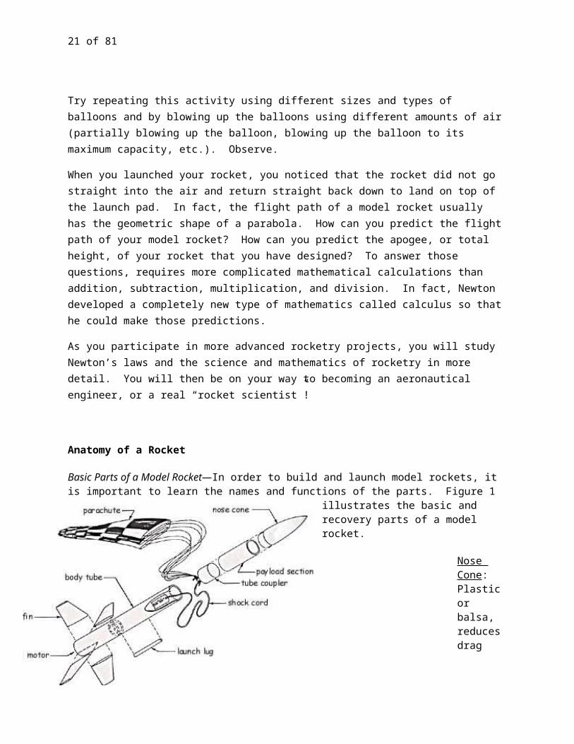
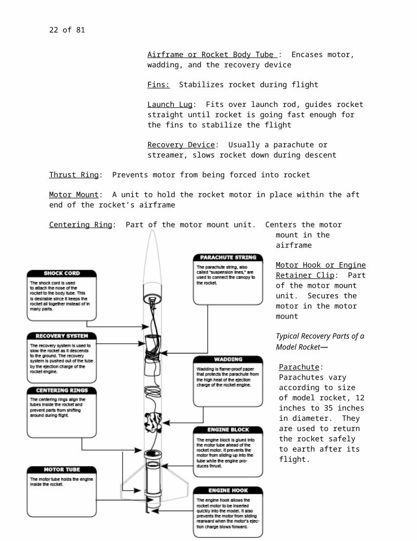
Basic Parts of a Model Rocket—In order to build and launch model rockets, it is important to learn the names and functions of the parts. Figure 1 illustrates the basic and recovery parts of a model rocket.
Nose Cone: Plastic or balsa, reduces drag
Airframe or Rocket Body Tube : Encases motor, wadding, and the recovery
device
17 of 60
Fins: Stabilizes rocket during flight
Launch Lug: Fits over launch rod, guides rocket straight until rocket is going fast enough for the fins to stabilize the flight
Recovery Device: Usually a parachute or streamer, slows rocket down during descent
Thrust Ring: Prevents motor from being forced into rocket
Motor Mount: A unit to hold the rocket motor in place within the aft end of the rocket’s airframe
Centering Ring: Part of the motor mount unit. Centers the motor mount in the airframe
Motor Hook or Engine Retainer Clip: Part of the motor mount unit. Secures the motor in the motor mount
Typical Recovery Parts of a Model Rocket—
Parachute: Parachutes vary according to size of model rocket, 12 inches to 35 inches in diameter. They are used to return the rocket safely to earth after its flight.
18 of 60
Parachute Shroud Lines: A series of thin strings attached to the parachute enabling the parachute to billow out, catching the wind, to slow the flight descent.
Shock Cord Mount: A system used to connect the shock cord to the airframe.
Shock Cord: The shock cord connects the airframe to the nose cone eyelet so they do not become completely separated upon deployment of the parachute.
Nose Cone Eyelet: Where the top of the shock cord and the parachute shroud lines connect to ensure completely separated upon deployment of the parachute.
Recovery Wadding: Flameproof (material) used to keep the recovery system from melting or burning.
SYSTEMATIC PROCESS OF MODEL ROCKET CONSTRUCTION
Both Unit 1 and Unit 2 have a separate supplemental booklet for model rocket construction. If you do not already have your supplemental booklet, be sure to get one from your club leader. They are as follows:
*Unit 1 Supplemental Booklet for Plastic Fins Only—Model Rocket Construction
*Unit 2 Supplemental Booklet for Balsa/Basswood Fins Only—Model Rocket Construction
*You may continue with your studies contained in this manual with “Elements and Principles of Rocket Flight” before or during construction of your model rocket.
Shock Cord
19 of 60
ELEMENTS AND PRINCIPLES OF ROCKET FLIGHT
Black Powder Rocket Motors---(color the areas on the motor)
Parts of a Solid Fuel Rocket Motor—
The following is a list of parts for a solid propellant motor:
Paper casing Ceramic nozzle with nozzle throat Solid propellant Smoke tracking and delay element Ejection charge Clay retainer
cap
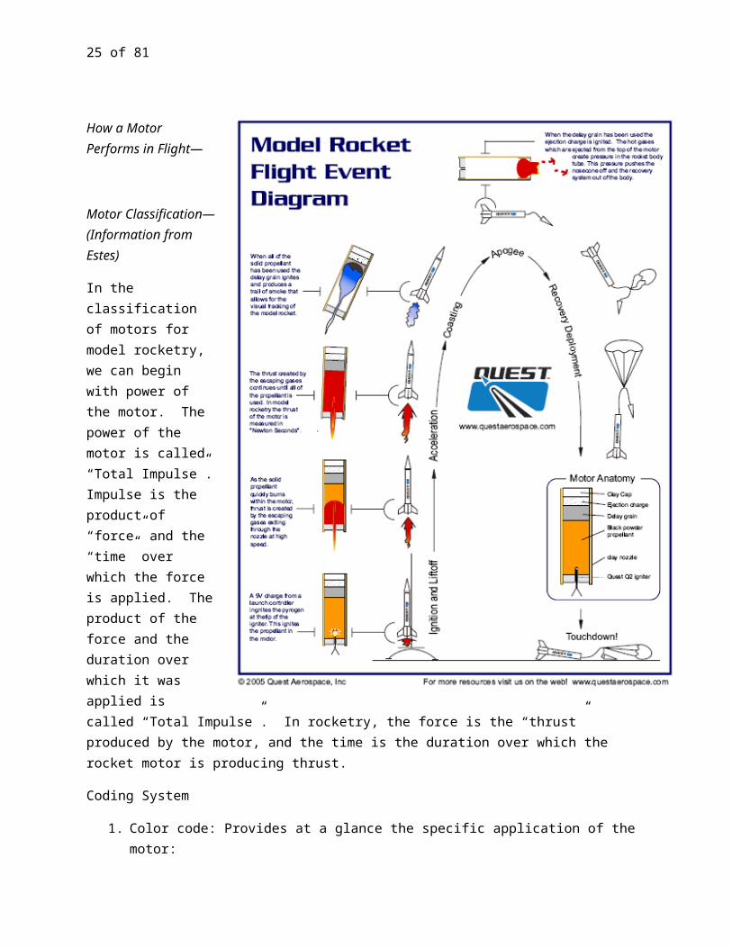
How a Motor Performs in Flight—
Motor Classification—(Information from Estes)
In the classification of motors for model rocketry, we can begin with power of the motor. The power of the motor is called “Total Impulse”. Impulse is the product of “force” and the “time” over which the force is applied. The product of the force and the duration over which it was applied is called “Total Impulse”. In
20 of 60
rocketry, the force is the “thrust” produced by the motor, and the time is the duration over which the rocket motor is producing thrust.
Coding System
1. Color code: Provides at a glance the specific application of the motor:
a. Green –Single engine
b. Purple –Upper Stage (on Multi-Staged Rockets)
c. Red –Booster Stage
d. Black –Plugged for special applications
2. Alpha-numeric code: Provides the motor’s performance information
Total Impulse Classification
This chart shows the approximate altitudes that can be achieved with single stage rockets.
21 of 60
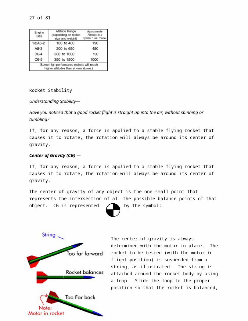
Rocket Stability
Understanding Stability—
Have you noticed that a good rocket flight is straight up into the air, without spinning or tumbling?
If, for any reason, a force is applied to a stable flying rocket that causes it to rotate, the rotation will always be around its center of gravity.
Center of Gravity (CG) —
If, for any reason, a force is applied to a stable flying rocket that causes it to rotate, the rotation will always be around its center of gravity.
The center of gravity of any object is the one small point that represents the intersection of all the possible balance points of that object. CG is represented by the symbol:
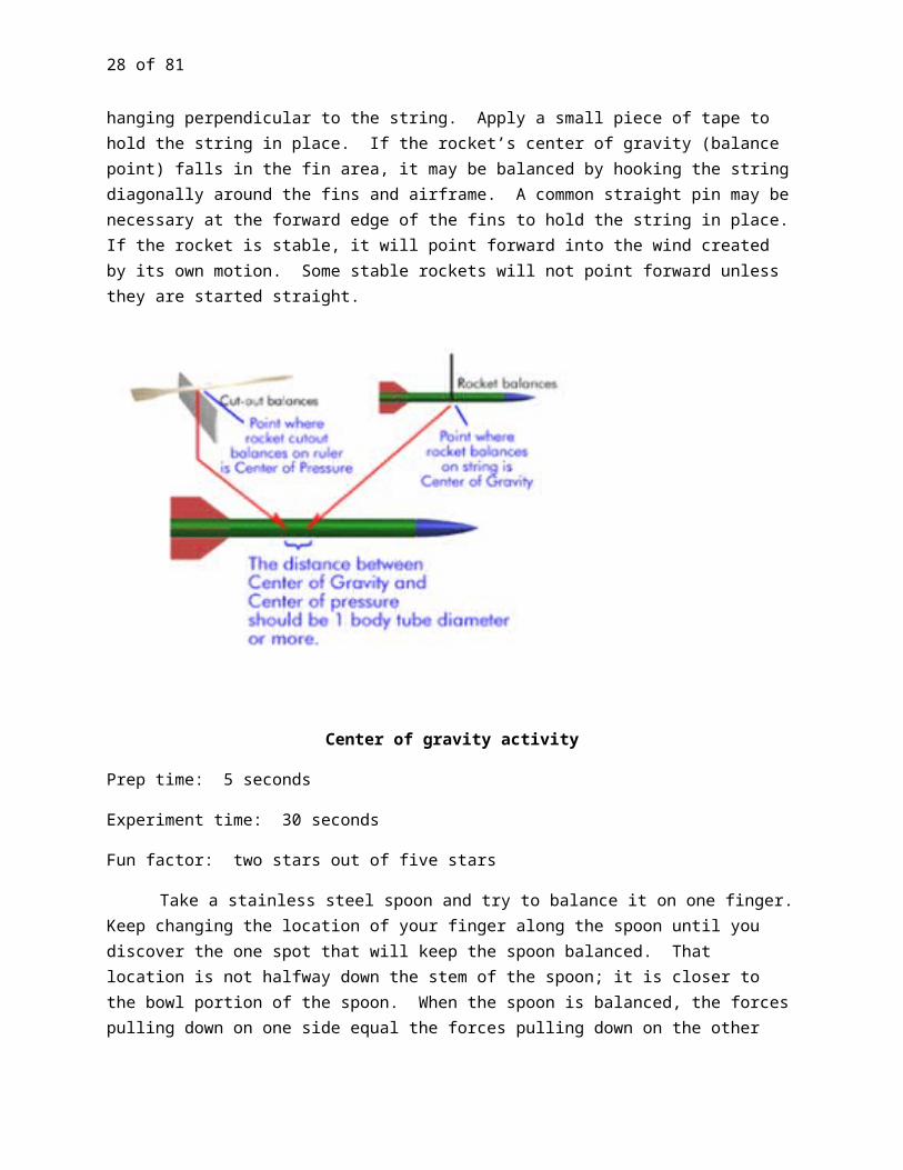
The center of gravity is always determined with the motor in place. The rocket to be tested (with the motor in flight position) is suspended from a string, as illustrated. The string is attached around the rocket body by using a loop. Slide the loop to the proper position so that the rocket is balanced, hanging perpendicular to the string. Apply a small piece of tape to hold the string in place. If the rocket’s center of gravity (balance point) falls in the fin area, it may be balanced by hooking the string diagonally around the fins and airframe. A common straight pin may be necessary at the forward edge of the fins to hold the string in place. If the rocket is stable, it will point forward into the wind created by its own motion. Some stable rockets will not point forward unless they are started straight.
22 of 60
Center of gravity activity
Prep time: 5 seconds
Experiment time: 30 seconds
Fun factor: two stars out of five stars
Take a stainless steel spoon and try to balance it on one finger. Keep changing the location of your finger along the spoon until you discover the one spot that will keep the spoon balanced. That location is not halfway down the stem of the spoon; it is closer to the bowl portion of the spoon. When the spoon is balanced, the forces pulling down on one side equal the forces pulling down on the other side, this balancing point is the center. Gravity is the force. The balancing point is called the center of gravity.
The center of gravity is important to make sure that an object remains stable. For example, car manufacturers need to determine the center of gravity of cars to determine how easy it is for a car to rollover during an accident. A vehicle such as a dune buggy has a low center of gravity so that it does not usually tip over when making a turn.
Center of Pressure (CP) —
As a model rocket flies through the air, aerodynamic forces act on all parts of the rocket. In the same way that the weight of all the rocket components acts through the center of gravity, the aerodynamic forces act through a single point called the center of pressure. CP is represented by the symbol:
One method to find the Center of Pressure of your Rocket
Step 1: Cut out a profile of your
rocket in cardboard. It does not haveto be the same size, but it doesneed to be accurate in shape and scale.
23 of 60
Step 2: Balance the cutout on the edge of a ruler. Mark the rocket where it balances. This spot marks the Center of Pressure of your rocket.For the rocket to be stable, the CG must always be forward of the CP, with a minimum distance of the diameter of the rocket’s body tube (airframe) between each.
A good way to keep the CP and CG symbols straight is CP is the one with the dot or point in the center. Think “Center of Pressure = Pressure Point.”
Other Factors that Affect Stability—
Numerous factors can cause a model rocket to become unstable in flight. A few of those factors are listed below.
“Crooked or Canted Fins: If you have fins on your rocket that are not perfectly straight, they have the potential to cause unexpected lift forces to be generated.
Fins Where the Airfoils Are Different: If each fin on your rocket has a different airfoil, this would have the same effect as crooked or canted fins. It generates non-uniform lift forces. The best airfoil on all the fins
would be the teardrop shape (symmetrical); but if it is not uniform on both sides, you have what is called a “cambered” airfoil. This type of airfoil is similar to those on the wing of an airplane, whose purpose is specifically to generate lift.
Forward Fins: These are any fins placed on the model in front of the Center-of-Gravity (CG). They are always destabilizing if they generate lift. Therefore, it is critically important that they be made as small as possible, and that they are “perfectly straight” on the model. If they are not, the model is probably going to be unstable. (Forward fins are also known as “canard” fins.)
Asymmetrical Fin Arrangements: The word asymmetrical means “not” symmetrical; in other words, fins that are not placed or spaced equal distances around the tube. It would also include having some fins on the rocket being bigger than others are. In either case, what happens is that the lift force on one side of the rocket can be bigger than on the other side. This can cause the model to do loop if it is hit by a sudden gust of wind (on the wrong side of the model).
The following was taken from “Why Do Rockets Go Unstable?” by Tim Van Milligan; excerpt from “Apogee’s Rocketry E-zine,” Issue #42 (03/04/01)

24 of 60
Fins That Pop Off During Flight: When this happens, the result is that the lift forces around the rocket are not uniform. This makes the rocket do loops, and it is easy to figure out after the flight, if you are fortunate to find the parts afterward.
Loose Fins: Even if the fins do not pop off during flight, the reason we do not tolerate loose fins on the rocket is that they can vibrate back and forth. This disrupts the airflow on one side of the model, and can cause it to go unstable. So never, tape a fin onto a rocket or permit someone else to do so. This is just asking for trouble.
Loose Nose Cones That Are Canted in the Tube: This is similar to the Number 8 above, because a canted nose cone can generate more lift forces on one side of the rocket than the other can.
Rocket Binding on the Launch Rod: This is similar to the one above. The rocket hangs up for just a moment, decreasing its speed. When it lets go, now, it is not traveling fast enough.
Getting entangled in the igniter clips, preventing it from lifting off smoothly: This would be anything that slows the rocket while it is on the rod may be a detriment to the stability of the flight.”
Loose or Constricted Launch Lug: The sudden force of pressure applied to a loose launch lug after the motor is ignited can cause the launch lug to snap off. The rocket will respond by twisting, causing it to cant or turn horizontal before even leaving the distance of the launch rod.
Constricted Launch Lug: Launch lugs that are not completely straight in line with the body tube, or has decals placed in front or behind it, are factors that can cause the launch lug to bind against the launch rod. The results can cause the rocket to decrease in speed prior to leaving the pad, hang up on the rod and not leave the pad, or cause the flight to become unstable.
TYPES OF RECOVERY SYSTEMS
As part of a successful launch, the rocket must return to ground level safely. Several types of recovery systems are used to slow the speed of the rocket, allowing for the safe return of the rocket.
Parachute: The most common method of recovery used to bring your rocket down safely.
Streamer: Long narrow strips of plastic that help break the fall of the rocket.
Featherweight: Is a small lightweight rocket that floats back to earth.
Tumble: Is similar to a featherweight except the rocket uses tumbling motion to help break its fall.
Helicopter: The rocket uses a revolving or spinning motion to help break its fall. Helicopter recovery systems generally consist of rotary blades of some type.
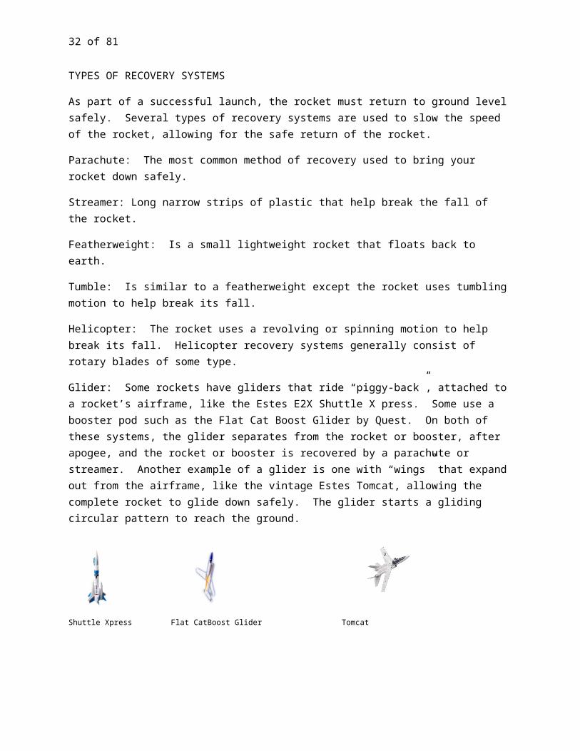
Glider: Some rockets have gliders that ride “piggy-back”, attached to a rocket’s airframe, like the Estes E2X Shuttle X press. Some use a booster pod such as the Flat Cat Boost Glider by Quest. On both of these systems, the glider separates from the rocket or booster, after apogee, and the rocket or booster is recovered by a parachute or streamer. Another example of a glider is one with “wings” that expand out from the airframe, like the vintage Estes Tomcat, allowing the complete rocket to glide down safely. The glider starts a gliding circular pattern to reach the ground.
25 of 60
Shuttle Xpress Flat CatBoost Glider Tomcat
LAUNCH SYSTEMS AND FIELD OPERATIONS
Parts of a Model Rocket Launch System
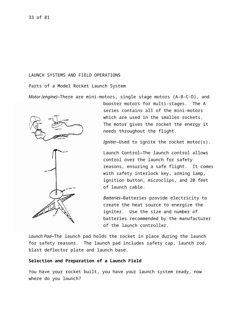
Motor (engine)—There are mini-motors, single stage motors (A-B-C-D), and booster motors for multi-stages. The A series contains all of the mini-motors which are used in the smaller rockets. The motor gives the rocket the energy it needs throughout the flight.
Igniter—Used to ignite the rocket motor(s).
Launch Control—The launch control allows control over the launch for safety reasons, ensuring a safe flight. It comes with safety interlock key, arming lamp, ignition button, microclips, and 20 feet of launch cable.
Batteries—Batteries provide electricity to create the heat source to energize the igniter. Use the size and number of batteries recommended by the manufacturer of the launch controller.
Launch Pad—The launch pad holds the rocket in place during the launch for safety reasons. The launch pad includes safety cap, launch rod, blast deflector plate and launch base.
Selection and Preparation of a Launch Field

26 of 60
You have your rocket built, you have your launch system ready, now where do you launch?
Refer back to the NAR Model Rocketry Safety Code to ensure you are following all the required rules related to launching your rocket. In selecting your launch site, also check with your local law enforcement for park restrictions relating to model rockets. It is also recommended and considerate to contact your local fire department to inform them that you will be performing a model rocket launch. If a fire ban is in place, there may be a no-cost permit you can obtain from the Fire Marshall in order to launch rockets.
The launch field should be devoid of power lines, trees, buildings and other obstructions. Prevent rockets form flying over spectators’ heads, including yours, by setting up the launch pad at an angle of 90 in relationship to the wind. Rope or mark off the launch range to prevent spectators from roaming -̊into the range. Set up a field table for rocket preparation, and if you are conducting a multiple flight event, set up a range table for the launch ignition system and data recording. Having a flag posted near the launch site is also helpful in tracking direction of the wind.
Setting up the Launch Pad System
If you are using a single portable launch systems (e.g. Estes Port-a-Pad or Quest’s Lift Off Model Rocket Launch Pad) to launch rockets with, be sure to set the pad up in an area free from dry grass or other easily burnable material at a minimum distance of 15 feet for D motors or smaller and 30 feet for rockets with larger motors. Remember to place the safety cap on the launch rod to avoid eye or other type of injuries. Tie the ignition key to the string attached to the safety cap. This will prevent an accidental launch from happening while you are working with your on the pad.
Do a simple tie with the power cord (micro-clip end) around one of the pad’s legs, looping it through the opening in the leg closest to the blast deflector. Be sure to leave enough length for the micro clips to reach up to the rocket’s igniter. This will help to prevent someone from pulling the igniter clips off or the igniter out of the motor when picking up the launch controller unit on the other end of the power cord.
Once you have placed the launch rod into the launch pad stand, immediately place the safety cap on top of the rod.
Tip #1: Tie the ignition key to the other end of the safety cap string. With the ignition key tied to the safety cap, an accidental launch of the rocket may be avoided while you are working with your rocket at the pad.
Tip #2: Sometimes a slight wind gust on heavier rockets can tip the launch pad system over. Either stake the legs down or strengthen it with some large rocks.
Flight Operation and Safety Check Procedures
Whether you launch your rocket by yourself or with a group, you always need to prepare for the unexpected. Always have near you the following range safety equipment: rakes or flapper rakes,
27 of 60
shovel, jugs of water and a fire extinguisher. In addition, always have on you a cell phone for calling for emergency assistance if needed.
Organized rocket club launches will usually set up a multiple pad launch system, sometimes set up for both model rockets and high power rockets, with the range roped off. Many will use a speaker system so all spectators can always hear what is going on, especially for “heads-up” flights. Moreover, most clubs require participants to complete a rocket log for each rocket flight for their club records and for the officers to use when announcing each launch.
Organized rocket club launches will appoint a minimum of two officers, a range safety officer (RSO) and a launch control officer (LCO). For major club launches, the officers must be members of either NAR or Tripoli. If you launch your rocket by yourself, you are responsible for following the NAR Safety Code and are responsible for any spectators who may be present.
Launch Operation and Safety Procedures
Whether you launch your rocket by yourself or with a group, you always need to prepare for the unexpected. At all times have near you the following range safety equipment: rakes or flapper rakes, shovel, jugs of water and a fire extinguisher. Always have a cell phone available for calling for emergency assistance if needed.
Organized rocket club launches will usually set up a multiple pad launch system, sometimes set up for both model rockets and high power rockets, with the range roped off. Many will use a speaker system so all spectators can hear what is going on, especially for “heads-up” flights. Most clubs require participants to complete a rocket log for each rocket flight for their club records and for the officers to use when announcing each launch.
Organized rocket club launches will appoint a minimum of two officers, a range safety officer (RSO) and a launch control officer (LCO). For major club launches, the officers must be member of either NAR or Tripoli. If you launch your rocket by yourself, you are responsible for following the NAR Safety Code and responsible for the safety of any spectators who may be present.
Range Safety Officer (RSO) Responsibilities—
Responsible for the safe operation of the rocket launch range.
Has the final authority to approve or deny launch of any rocket.
May also act as the rocket check-in officer.
May also act as the person in charge of assigning the rockets to the launch pads.
Launch Control Officer (LCO) Responsibilities—
Keeps the launch range running smoothly.
Assists RSO in maintaining safe range operations.
28 of 60
Operates the launch controller(s).
Controls whether a launch range is “open” or “closed.”
May act to assign rockets to launch pads.
Makes announcements over the PA system.
“Range is Open” means the LCO has removed the safety key from the launch control system, possible misfires have sat for at least one minute, and it is safe for you to approach the launch pads.
“Range is Closed” means the LCO has closed the launch pads for any further activity, and prepares to launch the rockets currently on the pads. No one is permitted to approach the launch pads for any reason.
Spectators are permitted to sit on chairs, but never on the ground primarily for their safety. Trying to quickly get off the ground when a rocket is coming in “ballistic” or to get out of the way of a rocket that “CATO” is nearly impossible to do.
“Ballistic” means the rocket’s recovery system has failed and the rocket is returning to earth at a very high rate of speed.
“CATO” means a catastrophic failure or a “catastrophe at take off.” Most CATOs are due to mishandling of motors, dropping them onto a hard surface, or storing them in uncontrolled temperature environments (freezing and thawing). Examples of CATOs: Motor and case separation, a crack in the motor casing or a crack in the propellant.
Spectators also need to be aware of “heads-up” flights at all times. A heads-up flight can consist of a ballistic or a CATO event, or it can mean the rocket about to be launch is of questionable stability or may be the first flight (maiden flight) for the rocket.
PREPARING YOUR ROCKET FOR FLIGHT
You have built your rocket, your launch site is properly set up, and now you want to launch it into the sky. Here are four key steps you need to perform to prepare your rocket for flight.
Recovery Wadding
Recovery wadding is material used to protect your rocket’s recovery system. Wadding must be both flameproof (flame retardant) and biodegradable. Common types of wadding are flameproof tissue wadding and cellulose fiber, commonly known as “Dog Barf.” Estes Industries, Inc. first developed the tissue wadding from common toilet paper, coating it with a flame retardant agent. Dog Barf is actually Cellulose insulation, composed of 75-85% recycled paper filler (usually newspaper material) and 15% fire retardant such as boric acid or ammonium sulphate. Tissue wadding may be purchased at most hobby stores and online web stores. Cellulose insulation can easily be obtained at a local hardware store, usually under $10 a bail, which will last you a lifetime of rocketry.

29 of 60
Wadding is use to seal off any vents (air holes) above the motor. This prevents the hot gasses from the ejection charge to reach the recovery system. If the hot cases were able to reach the recovery system, they would melt the recovery system and burn through the shock cord.
When using tissue wadding, the number of sheets to use depends on the size of the rocket’s airframe (body tube). Your kit instructions will usually tell you how many sheets to use. Generally, you will use from 3 to 6 sheets per rocket flight.
1 2 3 4 5 6 (sheets)Steps to follow when using tissue wadding:
Gently “crumble” each sheet of wadding, individually. Do not wad into a tight ball.
Insert each sheet, individually, into the body tube, pushing it down as far as possible.
Blow the wadding to the top of the motor mount (or as far into the airframe as possible).
Experimenting with Parachutes
Parachute activity
Prep time: 20 minutes
Experiment time: 5-10 minutes
Fun factor: 2.5 stars out of five stars
Note: This experiment can be a tricky one to perform correctly. It is important to use the same toy figure or toy figures that are similar in shape and weight. If the toy figure does not weigh enough, then the differences between the drop times for the various sized parachutes will be negligible. The height for the drop also makes a difference. If you are standing on a kitchen chair, the differences in drop times for the various sized parachutes may not be significant; thus, it is important to drop the toy figures from at least eight feet above the ground. Finally, it is important to let go of the toy figure as opposed to tossing the toy figure.
Materials:
Plastic trash bags

30 of 60
Small toy figures of the same weight
Ruler
Tape
Strong thread
Scissors
Stopwatch
Friend
1. Make three different sized parachutes by cutting three squares from the trash bags: 3 inches on each side, 4 inches on each side, and 6 inches on each side.
2. Cut 12--12” lengths of thread and tape each piece to every corner of each square.
3. On each parachute, tie the four loose ends of a thread together, and then tape to the toy figure.
4. Predict which parachute will fall the fastest, and which will fall the slowest.
5. Stand at the top of the stairs, the top of a slide, or on a balcony and let go of the figure. Have a friend use a stopwatch to time how long the parachute takes to land.
What happens? The figure with the larger parachute will take longer to reach the ground if the figures are all the same.
Why? The larger parachute has a greater surface that is exposed to the air and thus encounters greater drag. The force of the air friction or drag slows the descent of the figure with the large parachute.
The concept of drag is important for the recovery system of your rocket. You will notice that a bigger parachute will float in the air and will take longer to land. This is especially critical if it is windy. The wind will catch your rocket and carry it farther away from your launch site. In addition, the size of your parachute and the weight of your rocket are critical. If you borrow a parachute from a rocket kit and that rocket weighs much less than your rocket, you may have a problem with rocket recovery; your rocket will return to the ground much faster and the harder landing may damage the rocket.
Sometimes, rocket kits will provide a parachute and will then have you cut a hole in the middle of the parachute. The hole is to decrease the force of drag and to increase the speed of the falling rocket so that it returns to the ground much faster and is not carried farther away in a breeze so that it lands closer to the launch site. However, if you cut too large of a hole, the rocket will fall too quickly and become damaged.
Preparation of a Parachute or Streamer Recovery System
31 of 60
Spread the plastic streamer or parachute flat and rub talcum powder onto both sides of the parachute. Be sure to cover each side thoroughly from edge to edge.
Never wad and stuff your parachute or streamer into the rocket. You may follow your kit instructions on how to fold your parachute or streamer or follow the steps below.
For a streamer, start by folding it end to end in half several times, depending on the size of the streamer. When you get to about 2- to 3-inches in length, roll the streamer the rest of the way, tight enough that it will slide easily into the rocket’s airframe.
For a parachute, start by folding the parachute in half, making a half circle. Continue folding the chute into triangles by taking one outside edge corner, bring it into the center bottom edge of the chute, and repeat with the opposite side. Continue folding the chute in by triangles until you have a size small enough to fit your rocket’s airframe.
Make sure the parachute shroud lines are straight. Place the shroud lines inside the folds of the parachute or gently wrap them in a neat row around the parachute. Do not pull the shroud lines too tight or allow them to hang too loose, which can cause tangles or hang-ups.
Insert as much of the shock cord into the rocket as possible first, followed by the streamer or parachute and the rest of the shock cord. Do not stuff the recovery system too tightly into rocket. The parachute or streamer should easily slide in and out of the airframe. Make sure the recovery system is placed below the “neckline” of the nose cone.
The rocket’s nose cone should be loose fitting, but tight enough not to fall out when held upside down and lightly shaken. Add masking tape to the nose cone until you get a proper fit. Make sure the shroud lines and the shock cord are not sticking out of the rocket or stuck between the nose cone and the airframe, which can cause the nose cone to bind and not deploy properly, if at all.
Motor Installation
Insert the motor into the rear of the rocket, nozzle end pointing out.
32 of 60
For friction fit motor mounts, add masking tape to the motor if the motor appears to be too loose.
Installation of an Igniter
To ensure proper handling:
Do not tear Do not cut Do not remove the tape between the two lead wires of the same igniter.
This tape holds the lead wires in place to prevent shorts and to provide strength to hold the igniter’s shape. You may cut the tape to separate igniters on the same strip.
The keys to successful igniter installation are to insert the igniter all the way to the bottom of the nozzle and to secure the igniter firmly in place. If the igniter tip does not actually touch the propellant the igniter will “burn,” but the propellant will not be heated enough to initiate combustion. If the igniter is not firmly secured in the correct position, the small weight of a microclip and its lead wire may be enough to pull the igniter slightly away from the propellant.
After the igniter is properly inserted, push an igniter plug into the nozzle. This will bend the lead wires to one side a little. However, do not bend the lead wires before inserting the plug. Bending the wire before inserting the plug will pull the tip of the igniter away from the propellant.
After inserting the igniter and igniter plug in your model rocket motor, carefully bend igniter wires back and form leads into a “U-shape”. This provides two points to which each microclip is attached instead of one and will give you a better chance of having a successful ignition.
Placing the Rocket on the Launch Pad
Remove the safety cap (with ignition key attached) from the launch rod. Place the model rocket on the launch pad by placing the launch rod through the launch lugs. If you are using a port-a-pad system that sits on the ground, be sure to replace the safety cap onto the launch rod.
The next step is to attach the microclips. To do this you want to make sure that the microclips are clean. Do not allow the microclips to touch each other, the launch rod or the blast deflector plate. You are now ready for the countdown.
Launching Your Rocket
Launch Procedures
Whether you launch by yourself, as a family, with friends or with a rocket club there are procedures you should follow as you prepare to launch your rocket.
1st) Close the range. If you are launching with an organized rocket club, the LCO will ultimately be the one who will close the rocket range. However, if you are launching as a family or with a group of
33 of 60
friends, you need to announce to all spectators that the range has been closed. Be sure that you everyone’s attention when you prepare to launch your rocket.
2) Verify Electrical Continuity. The LCO (or you) will announce if you have continuity. If you are using a port-a-pad, you perform this task by inserting the launch key into the launch control box. If the light turns on, then you continuity and you are ready for the next step. If not, you may want to check your batteries.
3) Perform Range Safety Check. Make sure the launch area is clear of any obstructions or people. Check the sky for planes, parachutists, ultralites, etc. This is also the responsibility of the RSO. Ultimately, anyone can stop a launch at any point in the launch count. As you are focus on your countdown procedures, you may not be aware of an interference approaching your launch range, and you should advise your spectators to keep an eye and ear open to any possible interference.
4) Proceed with Launch Countdown. Most rocket clubs’ LCO will perform the countdown for you. Some will even perform the actual launch. However, if you are performing this duty yourself, make sure the spectators are aware that you are in the process of launching by counting down in a loud voice. If you have someone tracking or spotting your rocket for you, be sure, you have his or her attention. Again, at any point during the countdown, a halt to the launch can be called by the RSO, the LCO, a spectator, and yourself. For LPR (low power rockets) or model rockets the countdown usually starts at five counting down to one and then launch. For HPR launches, countdowns usually start at 10, giving all spectators time to become alert to the launch which is about to occur. Perform your countdown and launch. If your rocket for any reason misfires, remember to wait one minute before approaching your rocket or get permission from the LCO to approach the launch pads.
Ignition Misfires
Ignition misfires mean the motor failed to ignite. This can be caused by a broken igniter, a break in the electrical circuit, or an igniter pulled away from contact with the motor propellant. NEVER approach a rocket immediately following a misfire, as it is possible that the ignition is just delayed. According to the NAR Model Rocketry Safety Code, wait one full minute prior to approaching a rocket that misfired.
Rocket Recovery
When recovering your rocket, you must first find out if the range is “open,” if your rocket is still on the launch pad or if it landed within the rocket launch range. If there are still rockets waiting to be launched on other launch pads, do not approach your rocket until the LCO has given you permission. If your rocket has landed outside of the range site, and you do not have to cross into the range site to retrieve your rocket, than it will be safe for you to recover the rocket. When you have permission to recover your rocket, never run to retrieve the rocket. When running, it is very easy to stumble, trip or run over your rocket.
Checklists

34 of 60
The following two pages are checklists for you to use when you plan to launch your rocket. The checklists include what you look for in a launch site, what you need to set up a launch range, and the procedures to follow for launching your rocket. To ensure you have a safe and fun launch, make a copy of the following checklists each time you set out to launch your rocket.
To record your rocket’s flight information, attached is a Rocket Flight Log Sheet. Did you build the rocket yourself? Was it a Ready-to-Fly kit? Did someone loan you a rocket to launch? Make a copy of the Rocket Flight Log Sheet and complete one sheet for each rocket built or flew. You may record information for two flights per rocket. Complete as much of the information as you can and add these sheets to your project record book.
LAUNCH SETUP AND RANGE EQUIPMENT CHECKLIST (change shield to deflector)
Launch Flight Permission: No Fire Bans Obtained Fire Marshall Permission
Launch Site Permission: Land owner’s permission OR City, State or National Parks (Local Authorities’) okay
Launch Site Needs: Review the NAR Model Rocketry Safety Code Site free from power Lines, trees, buildings, etc. Launch surface—asphalt, cement, gravel, bare ground, green grass, or covered with a flameproof
platform.
Individual Field Safety Preparations (Launching without Spectators or an Organized Rocket Club): Leaf rake or flapper rake Shovel Fire extinguisher Jugs of water Cell phones with fire department number on speed dial Field table for preparing your rocket for flight Launch Pad System— Electronic Control Unit Fresh Batteries Launch Pad Stand Unit Blast Shield Launch Rod Safety Key Safety Cap, if applicable, in place on launch rod Standoff clip, i.e. clothespin (used for raising the rocket off the blast shield, if needed, for ignition
clips)
Group/Club Field Safety Preparations (Launching with Spectators): Checked off prior list Ropes to mark off range site Flag(s) for wind direction
Launch System Control Table Data Recording Table (Registration Sign In)
PA System, if applicable Appoint LCO Name: Appoint RSO Name:
Range Box Equipment and Supplies: Masking tape Baby powder
35 of 60
Needle-nose pliers Long thin dowel rod or probe (for pushing
down wadding or pushing out motor) Motors Motor Plugs Igniters Parachutes and streamers (different sizes)
Fishing Swivel Hooks (for quick recovery system changes)
Wadding or Dog Barf Super Glue (for quick fixes) Acetone (to unstuck fingers) Hobby craft sticks (for applying Super Glue) Small cup container (for quick fixes) Tin can for spent motors, igniters and plugs
Individual Self: Hat Sturdy shoes or hiking boots Plenty of drinking water Sunscreen LotionOther Suggestions: Camera Lawn chairs Light snacks
Use with adult supervision only!
36 of 60
FLIGHT PREPARATION CHECKLIST
Rocket—Fins and Launch Lug(s): Aligned straight Securely attached with filletsRocket Stability: Center of Gravity (CG) is ahead of Center of Pressure (CP) No loose, cracked or broken partsRocket Recovery Preparation: Wadding properly placed into the rocket (No wad balls) Shock cord secured and in good condition Baby powder on plastic parachute or streamer Parachute or streamer properly folded and inserted into the airframe Parachute, streamer and shock cord properly attached to the nose cone Nose cone slides into airframe easily, not too tight and not too loose
Rocket Motor Preparation: Check the size of motor for rocket and weather conditions Properly fit motor into motor mount assembly (friction fit may require masking tape) Check condition of igniter (wires not crossed or broken, filament not broken) Insert igniter (top of igniter must touch the propellant) Insert motor plug (motor plug color correct for size of motor being used) Lightly shake rocket right side up to see if the motor and igniter are securely attached
Field Flight Preparation: Remove safety cap (with safety key attached) from launch rod Slide rocket onto launch rod via the launch lug(s) Replace safety cap (with safety key attached) onto launch rod Secure igniter clips onto the igniter (one per igniter wire) Check to verify igniter clips are not touching each other, the launch rod or blast shield Remove safety cap (with safety key attached) from launch rod and return to launch control box
Flight Procedure: Close the range Insert safety key (with safety cap attached) into launch control box—check for continuity Receive permission for launch from LCO and RSO, if launching with an organized club Advise spectators you are about to conduct a launch (if no LCO or RSO is present) Check field range for obstructions Check air space for obstacles Perform countdown (5 – 4 – 3 – 2 – 1 – Launch!) Remove the safety key from the control box
Misfires: Wait until the range is open or a minimum of one minute before approaching the rocket Replace safety cap onto launch rod before looking at your rocket Check for short in electrical current (igniter clips touching blast shield, each other or launch rod) Check for damaged or spent igniter and replace, if needed Remove safety cap and repeat “Flight Procedure”
Rocket Recovery: Obtain permission from the RSO to retrieve your rocket (if it landed within the rocket range site) Do not attempt to recover your rocket yourself if it landed high in a tree, on a power line or building Do not run towards your rocket For long-range recoveries, take a friend with you and bring plenty of water Re-pack your recovery system into the rocket at point of recovery (preventing cord and line tangles and tears)
37 of 60
ROCKET FLIGHT LOG SHEET(Use one Rocket Log Sheet for each rocket built or launched. Record up to two flights for each rocket.)
MEMBER ACTIVITIES:Did you build this rocket? (Y or N) ____________________________________ Did you paint this rocket? (Y or N) Did you launch this rocket? (Y or N)___________________________________ Total times this rocket was launched:
ROCKET DESCRIPTION PER KIT PACKAGING (Must meet your unit’s rocket criteria.):Name of Rocket Kit: __________________________________________ Manufacturer’s Name: Rocket Skill Level (check one): SL-0 Ready-to-Fly E2X Kit Quick Build Kit SL-1 KitRocket Weight without Motor: Rocket Length: Number of Fins: Fin Type: Plastic Fins Balsa Fins Basswood FinsRecommended Motors: Recovery System: Parachute Streamer
FLIGHT #1—LAUNCH INFORMATION (if launched):Date: Launch Site: Launch Conditions:Approx. Temperature: Humidity/Precipitation: Wind Direction: Approx. Wind Speed: Cloud Cover: Rocket Information:Motor Used: Recovery System Used: Launch Pad Information:System Used (check one): Single-Pad System Multi-Pad SystemNo. of Misfires (if any): Lift-Off Information (check one): Successful Lift-Off Hung-up on Rod or Stand-Off Support Caught on Igniter Clips Motor Failure Other: Flight Information (check one): Straight-Up Flight Spinning but Straight Corkscrew Ascent Unstable Horizontal Flight Weather Cocked Into the Wind Other: Recovery Information (check all that applies): Did Not Deploy Partially Deploy Deployed Fully Nosecone Separation Stable Descent Tangled Shroud Lines Motor Ejected Motor Mount EjectedLanding Information (check one): Soft Landing Hard Landing Non-Deployment (Nose Dive) Water Landing Landed in Tree Landed on Building Caught on Power Line Drifted Out-of-Sight Other: #1 POST-FLIGHT INFORMATION (describe any damage to rocket):
FLIGHT #2—LAUNCH INFORMATION (if launched twice):Date: Launch Site: Launch Conditions:Approx. Temperature: Humidity/Precipitation: Wind Direction: Approx. Wind Speed: Cloud Cover: Rocket Information:Motor Used: Recovery System Used: Launch Pad Information:System Used (check one): Single-Pad System Multi-Pad SystemNo. of Misfires (if any): Lift-Off Information (check one): Successful Lift-Off Hung-up on Rod or Stand-Off Support Caught on Igniter Clips Motor Failure Other: Flight Information (check one): Straight-Up Flight Spinning but Straight Corkscrew Ascent Unstable Horizontal Flight Weather Cocked Into the Wind Other: Recovery Information (check all that applies): Did Not Deploy Partially Deploy Deployed Fully Nosecone Separation Stable Descent Tangled Shroud Lines Motor Ejected Motor Mount EjectedLanding Information (check one): Soft Landing Hard Landing Non-Deployment (Nose Dive) Water Landing Landed in Tree Landed on Building Caught on Power Line Drifted Out-of-Sight Other: #1 POST-FLIGHT INFORMATION (describe any damage to rocket):

38 of 60
[Congratulations! You have successfully completed Model Rocketry Fundamentals. If you chose to complete Unit, 1 (or 1A)’s Supplement Booklet for Plastic Fins for your exhibit project, we recommend you complete Unit 2 (or 1B)’s Supplemental Booklet for Balsa/Basswood Fin.
To exhibit your rocket at fair, you must enter in the highest unit level completed for the year.]
39 of 60
UNIT 1 SUPPLEMENTAL BOOKLET FOR PLASTIC FINS ONLY—MODEL ROCKET CONSTRUCTION
SELECT A ROCKET KIT AND GET ORGANIZED
Where to Look for Rocket Kits
Model rocket kits and launch supplies can be purchased in almost any hobby shop and toy store. Some carry an assortment of rocket kits designed for all ages and levels of skill, from simple starter kits to complicated scale models, but the selection of rocket manufacturers and kits may be limited.
Coupons—Watch for store coupons via local coupon fliers, booklets, newspaper or the Internet.
Catalogs—Manufacturer catalogs usually can be found free in hobby stores, or you may want to write to a manufacturer and request a copy of their catalog. (See List of Manufacturers under Resources.)
Internet—The Internet is another source for purchasing model rocket kits. Look for vintage rockets on Internet auction sites such as eBay. Many manufacturers specialize in types of rockets: SL-0 through SL-3 model rocket kits, SL-2 through SL-5 mid and high power rockets, novelty type rockets, rocket gliders and even experimental rocket kits. Refer to Resources in the back of this manual for website information.
Selecting Your Rocket Kit
Unit 1 members are required to build a simple 3 to 5 finned Skill Level 1, E2X or Quick Build rocket. Be sure the rocket kit you choose meet the requirements as stated in the “Unit 1 Rocket Criteria Requirements” listed at the beginning of this manual.
Check Condition—
When purchasing your rocket kit, verify that the body tube(s) nose cone and fins are in good condition. Body tubes are easily crushed or crinkled before the package is opened.
Skills and Knowledge, Not Size—
Members are not judged on the size of the rocket, but rather on the skills and knowledge learned, and the quality of the construction and finishing of the rocket.
Inventory Your Rocket Kit
Carefully open the kit package ---
Many online hobby stores are in business.
40 of 60
Most kits contain one or two very small parts, so be careful when opening your kit package.
Look for Missing Parts—
Refer to the list of items in your kit instructions and check for missing or badly damaged parts. If you have missing or damaged parts, consider returning the kit to the store for a replacement kit.
Determine What Supplies Are Needed—
Check your kit instructions for supplies you will need to construct your rocket. Also refer to the section “A Well-Equipped Rocketry Tool and Range Box” for suggestions and hints.
Find an Appropriate Work Area
Your work area should include plenty of workspace, good lighting, and proper ventilation. For rocket construction, you can safely perform the work inside the house or inside a garage with good ventilation. If any painting is necessary or desired, it will be necessary to set up a protected area in a well-ventilated garage or an area outdoors, blocked from the wind.
Safety First! Working with glue and paints require good ventilation!
Protect Your Work Area—
Cover your work area with a protective plastic sheet, white or brown paper such as butcher paper or flattened paper bags. Do not use newspaper to cover your work area as the newsprint can transfer to your rocket parts and yourself.
Working with Glues—
Work with water-soluble glues if possible for easy cleanup. Wear protective gloves to avoid getting glue on your hands, and refrain from touching your face when working with glue.
Practice Patience
The old saying goes: “Patience is a virtue.” You can avoid many unnecessary mistakes, repairs and cleanups by taking your time and not “rushing” into a task.
Read Your Kit Instructions Entirely Before You Start
Another way to avoid mistakes is to read the instructions prior to starting any construction on your rocket kit. After reading the kit’s instructions, also review the construction techniques listed in this booklet for each phase of your build process.
A WELL-EQUIPPED ROCKETRY TOOL AND RANGE BOX
Construction Supplies and Tools for Plastic Model Kits
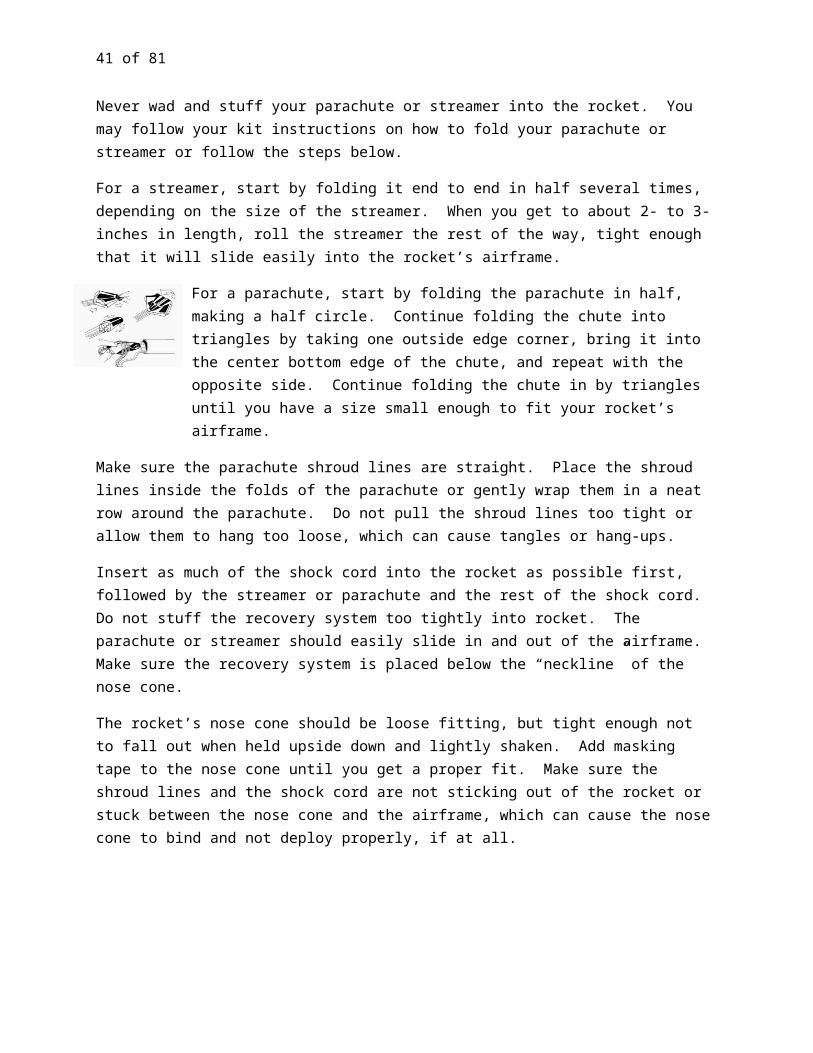
41 of 60
Applicators—(Toothpicks, hobby sticks, etc.,) Use for performing application tasks such as applying glues, adhesives, fillers, decals, etc
Glue ---Use to glue paper shock card mounts, shock card knots, motor mounts, and for fillets ( a thin line of glue along fins and launch lugs.) Recommend water-based glue, such as clear drying white glue or yellow carpenter’s wood glue (preferred). You may purchase wood glue at most hobby stores and home improvement stores. Glues come in many container sizes. One brand of wood glue comes in a small, “pen-shaped” container with a small nozzle end, and easy to refill.
Glue for Plastic onto Cardboard ---Use to glue plastic fin units to the rocket’s cardboard airframe (body tube). Suggested glues: E6000, Epoxy or a general-purpose adhesive. Check the label on the glue to see if it is compatible for plastic and cardboard. NOTE: Adult supervision is required for most of these gules, as well as proper ventilation.
Hobby Knife—A soft grip hobby knife with a protective blade cap and extra blades. Use to remove flashing on nosecones or other plastic parts, the inner mold from the nosecone eyelet.
Pencil (Mechanical or Standard) ---Use to mark lines on the rocket for part placement. Tip: Never use a pen to mark lines as the ink can be seen under the paint.
Plastic Modeling Cement ---Use to glue plastic parts together. Plastic cement comes in both liquid and gel forms. The liquid form is generally easier to use and control. Tip: Testers cement for plastic models works well with most plastic model kits. NOTE: May require adult supervision and requires proper ventilation.
Ruler— Use for measuring where the launch lug, the motor mount and other parts of the rocket may fit together. A small 6-inch or 12-inch hard plastic or metal ruler is recommended.
Sandpaper (400, 600-Grit to Micro-Fine, recommended but optional)—Use for sanding plastic edges or smoothing out the seemliness of the nosecone, and sanding grove lines filled with wood filler on the rocket’s airframe (body tube).
Scissors—For cutting out patterns, decals, and shock cord mounts, shroud lines etc., as needed.
Optional Build Equipment and Supplies
Airbrushes—If you are skilled in using airbrushes, they can be an excellent tool when painting a rocket.
Cardboard Box (Oversized)---Use as a paint box for your rocket.
Cloth (Tack Cloth, Micro-Fiber Cloth, or Lent-Free Towels)—Removes residue from parts of the rocket during the sanding and painting processes.
Crafter Gloves-- Use to protect your hands from glues, chemicals and paints, keeps the oils of your hands from transferring to your rocket causing some paints to not adhere well to the rockets, etc.

42 of 60
Containers with Lids (Small Plastic) –Use when working with glues or to mix wood filler with water in to form a workable paste. (Only if you choose to fill in the body tube groves, will you need any wood filler).
Elastic Binding Card (1/16”, 1/8” or ½”) ---Use instead of the rubber-band shock cord. The rubber band shock cords tend to become dried out and brittle, breaking after a few flights.
Face Mask or Scarf---Safety prevention tool to keep from breathing in sanding particles or fumes from glues and paint.
Glue Application Tips ---Small tips that can be connected to plastic cement tubes to provide a thin line of glue.
Hobby Syringe or Eyedropper---Use to apply two or three drops of water at a time t o wood fillers.
Masking Tape (Automotive Grade)---For masking off areas of the rocket you do not want to paint.
Modeling Plastic Putty---Fills in dips, seam lines, and scratches on external plastic parts.
Paint Drapes or Newspapers---For masking off areas of the rocket you do not want to paint.
Paint Supports or Stands---A means to prop the rocket nosecone and/or rocket for painting. See suggestions given under “Painting Techniques.”
Paper Towels or Soft White Cloth---Use for quick cleanups.
Right-Angle Metal Bar ---Use to assist in drawing straight lines along the body tubes. NOTE: Door frames or any right-angle object can be used this technique.
Safety Goggles---May be used when painting to protect the eyes from overspray.
Sandpaper (320-and 400-Grit) –If you choose to paint your rocket, use the sandpaper for sanding wood filler placed in the groves of the airframe’s body tube. Also, use sandpaper to remove the waxy coating on the body tube.
Sealer/Finishing Clear Coats---Use to secure decals and for providing a nice flat, matt or glossy finish to your rocket. (An optional technique.)
Spray Paint Gun (Plastic) –A plastic spray gun, which uses a trigger device, that can be attached directly to the spray paint can, making it easier to hold, control, and guide the flow of paint. Easily found at hardware stores.
Spray Paints for Top Coats—Use to paint your rocket (if desired). Some SL-1, E2X or Quick Build kits can be painted. Mixing different brands or paint for your primer, top and finishing coats could cause what is known as an “orange-peel” or bubbling reaction to the paint. Until you know for certain what works well together, it is recommended that you use the same brand name for all the various
43 of 60
stages of coats of paint. If you choose to paint your rocket in bright colors –yellow, red, orange—a first coat of white paint is recommended.
Spray Primer (Sandable)—Use a sandable primer prior to spraying on any top coats! Gray, white or rust sandable primer is acceptable.
Super Glue—Use for reinforcing the ends of body tubes and for quick field repairs. NOTE: Adult supervision is required.
Transfer or Decal Paper---May be used to create your own decals.
Tweezers—Use for parts that are too small to be readily picked up with your fingers.
Wood Filler (Water-based)—Fills in the grove lines on the rocket’s airframe (body tube). Look for fillers that are water cleanup, have no chemical odors, and are easy to sand and paint. Recommended examples: Elmer’s ProBond Wood Filler or Zar’s Latex Wood Patch.
Range Tools and Supplies
Acetone—Use for Super Glue removal from exposed skin. Tip: Finger Nail Polish Remover contains acetone and works well to remove Super Glue from skin. NOTE: Adult supervision required.
Baby Powder—Use on plastic parachutes and streamers to make the surface slick, making it easier for the parachutes and streamers to unfurl (open up). Also aids in locating the rocket in the sky when the recovery system deploys.
Container (Small) ---Good to have on hand when working with glues.
Dowel Rod (Long/Thin) or Probe—Helps to push down recovery wading towards the motor mount, and sometimes to help push out a motor that may have jammed up inside the airframe.
Hobby Craft Sticks---Good to have on hand when applying glues while at the launch site.
Masking Tape—Creates a better friction fit for nose cones and rocket motors.
Motor Plugs---Holds the igniter in the rocket motor.
Needle- Nose Pliers---Helps to pull out the hot, spent motor, and for opening and closing swivel snap hooks.
Parachutes—Most common recovery systems. Having several sizes available, some with holes and some without, makes it easy to do a quick change out for range and launch conditions.
Scouring Pad ---Use to remove any residue on the launch rod to prevent the launch lugs from hanging up on the rod. Recommend a heavy-duty commercial scouring pad made from synthetic fibers.

NOTE: Some plastic model rocket kits with parts like foil or metallic fin cans, nosecones, and airframes may not need any preparation.
44 of 60
Streamers---Use for quicker rocket descents, especially useful for smaller launch fields, colder days, and higher winds. Be sure to have a variety of sizes available to choose from.
Super Glue-- Use for quick fixes when on the launch site. Adult supervision required.
Swivel Snap Hooks---Use to attach parachutes or streamers for quick-change outs, and helps to reduce shroud line tangles.
PLASTIC MODEL ROCKET CONSTRUCTION TECHNIQUES
Each model rocket kit is unique in its design and construction. Be sure to read the kit’s instructions completely prior to starting any work. The following sections below suggest methods and techniques towards the building process of rockets in general. The following sections are listed in the order of recommended procedures and may not necessarily follow the same order of steps in your kit instructions. Be sure to review and compare each of the following sections with your kit instructions so you may apply the best technique or application for your rocket.
NOTE: Your model rocket kit may or may not require some of the following construction techniques. Reach each section to see if it would apply to your kit build. If it does not, then proceed to the next section.
Preparation of All Plastic Parts
Removing Plastic Flashing—
“Flashing” is leftover plastic from the molding process. With a sharp blade (hobby knife), trim all excess flashing off each part.
Safety First! Hold and guide your knife blade away from your body and remember to replace the safety cap when you are done with the hobby knife.
o Tip: Be sure to not scrape off any taps or pegs used to connect pieces together.
Wash Off Chemicals—
During the molding process, chemical agents are use to coat the molds so the plastic parts will not adhere to the molds themselves when formed. When the plastic parts are removed from the molds, an unseen residue of those chemicals can transfer to those parts, making it difficult for paints to adhere to them.
Use warm water with a couple drops of dishwashing detergent to wash off any residue chemicals (also referred to as “film”) from any exterior plastic parts, to include the nosecone and fins.
45 of 60
Gluing Plastic Parts
Safety First! Always work in a well-ventilated area when working with any type of chemical-based compound or glue.
Test Fit Parts Prior to Gluing
Make sure you are working with the correct parts, and that they fit together snuggly prior to gluing.
Application of Glue –
Use applicator tips, toothpicks, etc., something that will allow you to apply a thin line of glue. Do not use your fingers!
Safety First! Use protective gloves to keep the glue off your hands, especially when working with any type of plastic cement.
Apply Glue Sparingly!
Use glue sparingly and work quickly. Plastic cement heats up the plastic, effectively softening it (melting it) so both pieces join together to form one piece.
Tip: Do not use Super Glue or any type of quick repair glue for general construction. Sometimes, kit instructions will recommend a type of glue to use. Tester’s Plastic Cement generally works well for most plastic modeling construction.
Nosecone Preparation
After removing the flashing and washing off the nosecone perform the following steps:
Filling in Dips, Groves and scratches on the Nosecone---
You can use modeling plastic putty to fill in any dips, groves or scratches you may find on your nosecone, particularly along the mold seam lines. Once the putty has hardened, start with 400-grit sandpaper to smooth the filler down even with the body of the nosecone.
Safety First! Many types of plastic putty used for model craft have toxic and flammable vapors. Be sure to follow the product’s instructions for use and storage and use only in a well-ventilated area.
Tip: Check with your local hobby stores or do an Internet search for plastic putty.
Fine Sand the Nosecone
Use 600-grit or finer sandpaper to sand lightly the entire nosecone to a nice smooth finish. A smooth nosecone creates less drag on your rocket, allowing it to fly smoother and faster into the air. (Refer to

46 of 60
Newton’s Three Laws of Motion, the Law of Inertia.) Sanding a nosecone also allows primer paint to adhere to it better should you choose to paint your nosecone. Micro-fine sandpaper works well here.
Safety First! If you are sensitive to dust particles, use some type of facemask or scarf to keep from breathing in the dust created by sanding.
Tip: Avoid sanding too far down on the lip of the nosecone. The nosecone lip edge should line up with the outer edge of the rocket’s airframe.
Wipe down the nosecone with a micro-fiber cloth or Tack Cloth.
Tip: Do not press down and rub when using Tack Cloth as it will leave a sticky coating on the surface of the nosecone. Instead, just lightly brush the cloth across.
Test Fit Nosecone—
Test the fit of the nosecone “shoulder” (refer back to “Anatomy of a Model Rocket”) into the rocket’s body tube (also known as the “airframe”). The lip of the nosecone should match the outside edge of the airframe.
E a small piece of masking tap
The nosecone should fit snug enough that when you tip the rocket upside down the nosecone will not fall out, but not so tight that it is difficult to pull out.
Tip: If the nosecone easily fails out, take a small piece of masking tape and attach it to one side of the nosecone’s shoulder. Re-test fit the nosecone to the body tube. If the nosecone still falls out when e of the tipped upside down, add a little more masking tape to the nosecone’s shoulder until it fits properly.
Airframe (Body Tube) Preparation, If Needed.
The main body tube of the rocket, the one where all the parts fit onto, is the “airframe” of the rocket. Some rockets have more than one body tube to create either or longer or a wider airframe, or to serve as accessory parts to the rocket.
Model rocket body tubes are made up of several layers of paper/cardboard material and rolled to create a tube. Some plastic-finned rocket kits are manufacturer-finished or painted, and do not need to have anything done to them. Others—even those with colored airframes—may have large “roll” groves in them. These groves can cause drag on your rocket and can have an unseemly appearance to your rocket. You may leave them as they are, or you may fill in the groves to give your rocket a sleeker look and to eliminate the additional drag on your rocket.
Shoulder
Nosecone Airframe
Lip
47 of 60
If you choose to fill in the groves on your rocket, you will ultimately need to paint (or repaint) the airframe. Follow the steps below to prep your airframe.
Fill In Groves—
Put a small amount of wood filler into a small container and mix in just enough water to make it into a toothpaste-like consistency. Too much water can cause the cardboard to bubble, so use sparingly.
o Tip: Use an eyedropper or plastic syringe to apply two or three drops of water at a time.
With a small applicator (toothpick, hobby stir stick, or even your finger), pat the wood filler into the groves along the body tube. Try to keep it mostly in just the groves, for whatever excess is on the body tube will need to be sanded away later. Let dry completely.
Sand the wood filler smooth and even with the body tube. Start with 320 grit, wipe off residue, and repeat the steps with 400 and then 600 grit sandpaper.
o Tip: Use a tack cloth, a micro-fiber cloth, or dust-free towel to wipe off residue.
Remove Glossy Coating—
Even if your rocket’s airframe does not need to have any groves filled in, you may still want to paint it. Most airframes have a glossy coating to them, which should be remove prior to painting, making it easier for the primer paint to adhere to the airframe. Use 400 to 600--grit sandpaper to sand lightly away the glossy coating and to smooth out any bumps in the airframe.
Strengthen the Top End of the Airframe (Optional)—
The end of airframe where the recovery system deploys tends to start raveling or breaking down after a few flights. Strengthening the inside edge of the tube with a little Super Glue helps to keep the end from deteriorating too fast.
Safety First! Be sure to have adult supervision whenever using Super Glue and to always read the warning labels. Work in a well-ventilated area and have acetone nearby in case fingers are stuck. Nail polish remover has acetone in it and works well to removing Super Glue.
Depending on which end of the rocket the recovery system is deployed—front or rear ejection—paint on a thin layer of Super Glue inside the tube, from the top edge to about ¾” down. Let dry.
Take a small piece of 320- or 400-grit sandpaper and lightly sand smooth.
Re-test fit your nosecone to the airframe. If necessary, removes either excess masking tape or lightly sand the shoulder of the nosecone to obtain a smooth, but snug fit. Remember: the nosecone should come out easily when tugged, but not fall out when tipped upside down.
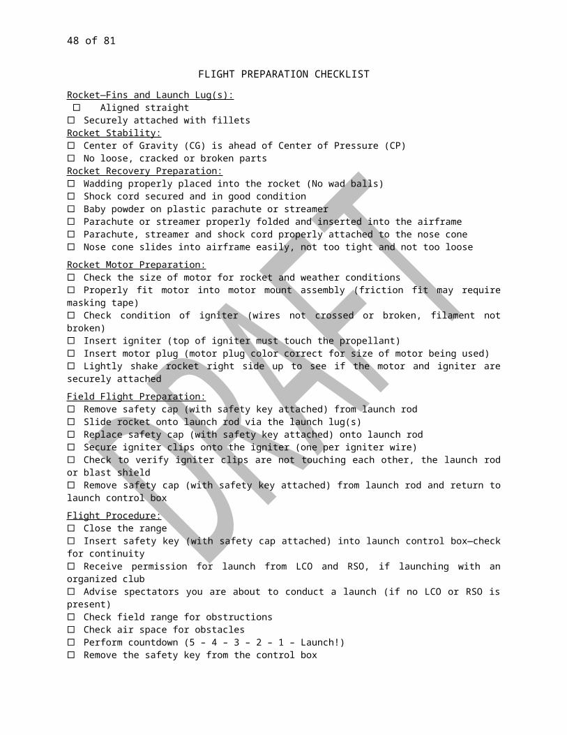
Fold Lines
48 of 60
About Shock Cords
Shock cords serve two main purposes for the rocket. First, they are used to connect the nosecone to the rocket’s airframe. Second, shock cords absorb the shock of force produced by the ejection charge of the rocket motor. The “force” is the result of the hot gasses created and released by the ejection charge.
Most Skill Level 0, Skill Level 1, Quick Builds and E2X rocket kits contain a shock cord made out of rubber band type material. Two other common types of shock cords for model rockets are elastic band material commonly used in sewing projects, and Kevlar cord. Rubber band shock cords will quickly dry out and become brittle. Elastic band shock cords, the type used for sewing, will generally last longer than the rubber band shock cords. However, these too will become charred from the hot gasses and will burn through or break over time. Kevlar cord is a flame resistant material, but it has no elastic material in it. Being flame and heat resistant, though, Kevlar shock cords will last longer than the other materials.
Shock cord length is also important. Shock cords need to be long enough to keep the nosecone from bouncing back into the rocket, which could cause damage. The “bounce back” is referred to as “recoil.” When you stretch a rubber band and release it, it recoils back to its original shape. Since Kevlar cord is not elastic, it needs to be long enough to absorb the shock of force applied to it, as well as long enough to keep the nosecone from damaging the rocket. A general rule to follow is to make your shock cord at least three times as long as your rocket especially if you are using Kevlar.
Methods of Attaching the Shock Cord.
There are numerous ways to secure the shock cord to a rocket. One of the methods is by attaching the shock cord to your motor mount. Read your kit instructions on how to connect the shock cord to your rocket and how to build your motor mount (also see “Motor Mount Assembly” in this supplement). Consider where you would like to place your shock cord to your rocket. You can always follow your kit instructions, or try one of these three methods:
Paper Shock Cord Mount Method—
Use this method with rubber band or flat elastic shock cords only.
Cut out the shock cord mount from the kit instructions or use the template shown here to make your own.
Follow your kit instructions on how to glue the shock cord to the shock cord mount. It is important that the shock cord is coming out at the top of the folds at a slight angle on the shock cord mount after all the folds are completed. Refer to the picture shown below.

Mound wood filler, let dry, and sand smooth.
49 of 60
While the glue is still wet, curve the shock cord mount around your finger with the smooth side next to your finger.
Place glue to completely cover the folded side of the shock cord mount and insert into the airframe. The top of the shock cord should be below the shoulder length of the nosecone, approximately 1 ½ “from the top of the tube. Press the shock cord mount against the interior of the airframe, making it as smooth as possible. Remove any excess glue from inside the tube. Bumps in the shock cord mount or rough dried glue on the inside of the tube could cause the parachute or streamer recovery system to snag and not deploy properly.
Through-The-Wall Method—
This method is best used with rubber band or flat elastic shock cords. Some kits use the through-the-wall method and use a small plastic cover to place over the knot.
Cut a small slit in the airframe near the center of the tube. Line the slit up with where a fin will be placed. This prevents the shock cord from getting in the way of the launch lug and launch rod.
Slip one end of the shock cord through the slit and secure the end with a double knot. Add a drop or two of white glue to the knot to secure it. Let dry.
Take some wood putty or filler and mold a small mound over the knot and onto the airframe. Round and smooth the mound towards the rear of the airframe to allow the airflow to glide over the mound, creating less drag on the rocket. Let dry.
Sand the mound smooth, but do not sand down to the knot.
The Motor Mount Assembly Method—
This method works best with Kevlar shock. If your kit comes with a motor mount already assembled, you will not be able to apply this method. Otherwise, be sure to read the next section on “Motor Mount Assembly” before proceeding with this method.
Glue the knot.

A
BC
Double Knots
50 of 60
There are several ways to connect the shock cord to a motor mount and some plastic model kits come with specific instructions as to how to connect the shock cord to a motor mount.
However, you chose to connect the cord to the motor mount assembly, remember the following steps:
Secure the end of the shock cord with a tight double knot.(See Examples A and B.)
Tip: File or cut a small groove inside the centering ring for the shock cord to rest into. This makes it easier for the centering ring to slide over the motor tube, motor hook and shock cord.
Tie the shock cord around the motor casing on the far side of the centering ring to give added security. (See Example C.)
Motor Mount Assembly
Many plastic SL-1, Quick Build and E2X kits come with a pre-built motor mount assembly. If yours does not, the parts generally required are the motor tube (holds the motor), motor hook (a metal clip), and one or two centering rings.
Read your kit instructions on how to build your motor mount completely through prior to assembly. Refer “To Motor Mount Assembly Method” above, if you decide to connect your shock cord to the motor mount. If your kit requires you to build a motor mount, follow the steps below. If not, you may proceed to the section “Learning about Fins.”
Building the Motor Mount:
Make a mark where the centering ring(s) go and where the motor hook inserts into the motor tube. Most kit instructions will have you cut a 1/8 inch slot about ¼ inches from the top of the motor tube.
Tip: Slightly pinch the motor tube end with your thumb and forefinger as you “gently” press down with the tip of the hobby knife. This will help you to avoid crushing the tube as you cut the slot.
Safety First! Be careful when applying pressure with the hobby knife. Less pressure will help avoid slips and possibly cutting your hand.
Secure the motor hook in place (in a straight line down the tube). With a piece of cellophane tape, secure the motor hook on the motor tube. This will help to prevent it from shifting or sliding out of position while you are placing on your centering ring.
Always test fit parts prior to gluing.
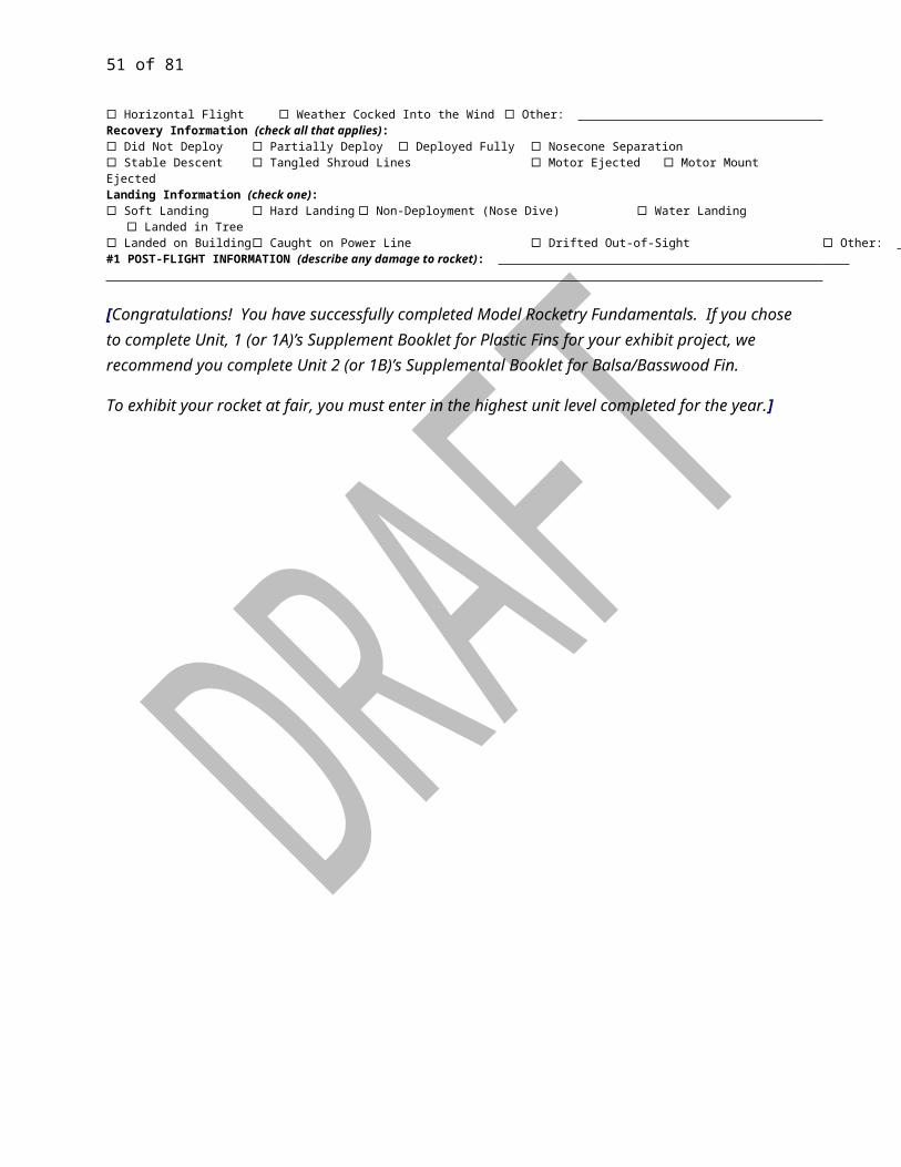
Marked Line Glue
Thrust Ring moves into tube.Line Marking
Push in to Line Marking
Motor
51 of 60
Apply enough glue to the motor tube about ½ inches from the centering ring line to allow you to slide and position the centering ring into the proper place. Wipe of the excess glue from the end of the centering ring with your finger. Leave some glue on the joint. Let dry.
Apply another line of glue on the other end of the centering ring. Stand on end and let dry. Glue applied to joints is called “fillets”. Fillets are used to strengthen parts together.
Securing the Thrust Ring---
If your rocket kit comes with a thrust ring, be sure to follow your kit instructions in the placement of the thrust ring. Either it may go directly into the rocket’s airframe, or it may be placed into the motor tube. Some basic steps to follow when gluing the thrust ring into the motor tube or airframe are as follows:
Make a mark on a motor (preferably a spent motor) about ¼” from nozzle end.
Mark an applicator stick about ¼ “shorter than the size of the motor.
Apply glue to the marked end of the applicator stick. Insert the applicator stick into the airframe (or
motor tube, per your kit instructions) up to the line you marked.
Apply the glue to the inside of the airframe (or motor tube). Be sure to spread glue all the way around the inside of the tube.
Place the thrust ring into the tube. Using the pre-marked motor, push the thrust ring up into the airframe (or motor tube). Continue to push up to the line marking on the motor. Quickly remove the motor.
Inserting the Motor Mount into the Airframe---
Again, read your kit instructions prior to inserting your motor mount into the airframe or your rocket. Some kits will have you insert the motor mounts even with the bottom of the airframe. Others will have you leave about ¼ “ to ½” of the motor mount to hang on the outside of the airframe.
The kit instructions should tell you how far down inside the airframe to apply the glue for the motor mount assembly. In general, you will apply glue into the airframe just short of where the centering ring will be placed. The glue will spread forward into the airframe as the motor mount is pushed into the airframe. The general steps to securing the motor mount into the airframe are similar to the steps used in gluing the thrust ring into the airframe (or motor mount).
Mark an applicator stick to the depth indicated in your kit instructions
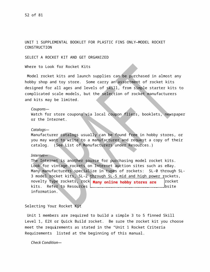
52 of 60
Apply glue to the same marked end of the applicator stick. Insert the applicator stick into the airframe up to the line you marked. Apply glue to the inside of the airframe. Be sure to spread glue all the way around the inside of
the airframe.
Tip: This is a case where more glue is preferred to less glue. Too little glue could cause the motor mount to “freeze” in place before getting it all the way into the airframe. However, too much glue can cause excess glue to run down the inside of your airframe and onto the shock cord.
In one quick motion, slide the motor mount into the airframe.
Tip: If you have already placed lines for your fins and launch lug onto your body tube, be sure to place the motor hook between two of those lines. Lining the motor hook along one of the fin lines could make it possible to put a motor into the motor mount. Lining the motor hook along the launch lug can cause interference with the launch rod and cause a short in the electrical current.
Once you have the motor mount into position, prop the airframe up with the motor mount end down, to help prevent excess glue from running down the inside of the tube. Let dry.
Apply a glue fillet to the outside joint of the motor mount to the airframe. Let dry.
Couplers and Payload Sections
Couplers—
Some model rocket kits include one or more couplers. Couplers are used to join two body tubes together to make a longer airframe. Sometimes, the body tubes are the same size in diameter, and sometimes they are not. So couples will also be used to change the airframe’s tube diameter from one section to another. Couplers are made from balsa, plastic or cardboard tubing. Couplers are sometimes glued on both ends, and sometimes just one end is glued.
Payload Sections---
Other model rocket kits may include a payload section. For most kits, the payload section is made from a clear plastic tube. Some common payloads are eggs, scientific experiments, and even liquids. Payloads sections usually have just one end glued to the airframe.
Recommended Glues for Couplers and Payload Sections----
Use wood glue when gluing cardboard or balsa parts to a cardboard body tube. To glue a plastic coupler or payload section to a cardboard body tube, it is recommended to use an E6000, Epoxy or a general-
53 of 60
purpose adhesive. Check the label on the glue to see if it is compatible for plastic and cardboard. NOTE: Adult supervision is required for most of these glues, as well as proper ventilation.
Learning about Fins
Fins come in all sizes and shapes. They are used to stabilize your rocket while in flight. The center of gravity (CG) and center of pressure (CP) are also determined by the size and placement of fins. Always remember to place your fins as your rocket kit instructions tell you. Commercial rocket kits are tested for proper fin placement and size, so you know that the CG and the CP will be in the right places on the rocket.
Most fins have three or four edges to them. All edges have a name. The “root edge” is the edge that will be glued to the rocket’s airframe. The “leading edge” is the edge that will lead into the sky. The “trailing edge” is the edge last to enter into the sky, and the “outboard edge” is the edge between the leading and trailing edges, also known as the “outside edge”. Two typical fin patterns are shown below.
Example 1 Example 2
Attaching the Fins or Fin Can Unit
Most plastic kit models either use a fin can unit or inset plastic fins (fins that fit through the body tube). Follow your kit instructions in the placement of the fins or the fin can unit.
Fin Can Units—
If you are using a fin can unit, be sure to check that the fit is snug against the airframe, and is not sitting slightly twisted or offset. Also, check the alignment with your motor hook and launch lug. Neither should be aligned with your fins. Note: Some rocket kits will have the launch lug built into the fin can unit.
Individual Fins—
Pre-fit each fin prior to gluing. Using plastic cement, place one fin into the fin slot on the airframe.
Make sure the alignment of the fins is vertical with the rocket’s airframe. Let dry and repeat procedure with the rest of fins.
Trailing Edge
Root Edge
Leading Edge
Leading Edge
Trailing Edge
Outboard EdgeRoot Edge
54 of 60
Safety First! Fins that are not correctly place on the rocket can cause your rocket to fly unpredictably.
If you attached your fins directly to the cardboard airframe, you can strengthen their fit by applying a thin line of glue called a “fillet”. Use clear-drying non-toxic glue, along both seams of the root edge for each fin. Smooth out with your fingertips.
Tip: Do not use plastic cement to fillet your fins, as too much glue could distort the plastic fins. (Remember, plastic cements have a chemical reaction, which melts plastic.)
Tip: Many plastic types of cement will not adhere to a cardboard airframe. There are other types of white glues that dry clear and can work well for this procedure. Example: Pinecar Pinewood Derby Formula Glue is fast setting nontoxic and nonflammable. It is rated for wood, paints, meta l and plastic.
Sometimes a second application of glue may be needed if bubbles form in the fillet.
Attaching the Launch Lug.
Most plastic model rocket kits have holes in the airframe to insert the launch lug into, or the launch lugs have been molded into the fin can unit. However, if you have a kit that does not already have a designated spot for the launch lug, follow the procedures below.
Check Placement of the Launch Lug—
Your kit may have the launch lug built into the fin can unit. If so, you may proceed to the section “Painting Techniques”.
Refer to your kit instructions for proper placement of the launch lug(s). If your kit provides a fin and launch lug alignment guide, be sure to use it to mark where each should be placed. Place the launch lug so that it does not interfere with the fins of the rocket or the motor hook. Small rockets generally use only one launch lug, but larger rockets may use longer launch lugs, two, or even three launch lugs in vertical alignment with each other. Generally, one launch lug is placed 1” above the fins, but it may also be placed along the edge of a fin. If using two launch lugs, the second launch lug should be placed about 1” down from the top of the airframe.
Alignment and Attachment of the Launch Lug—
It is important to align the launch lug vertical along the rocket’s airframe. If the launch lug is slanted any, it can bind against the launch rod on takeoff, which can cause the launch lug to tear off or partially off, causing the rocket to fly off in any direction.
Prepare your airframe by lightly sanding it in the general area where your launch lug will be placed. To align your launch lug properly, draw a straight line on the airframe by using a right-angle metal bar or a doorframe.
55 of 60
Lightly sand one edge of the launch lug (along the entire length of the launch lug.) Apply a slight amount of glue to both the airframe and the launch lug and let sit for about one minute. Apply a second slight amount of glue to the launch lug (in the same spot as before) and attach to the airframe. If you applied too much glue, the launch lug will easily slip off or out of alignment. Raise the rocket to eye level and hold out at arm’s length. Sight down the rocket’s airframe and launch lug to ensure proper alignment. Let dry.
Apply Fillets—
Apply fillets to both edges of the launch lug and smooth out with your fingertip. Be sure the glue does not close up the launch lugholes.
o Again, do not use plastic cement for this procedure, as it does not adhere well to cardboard airframes.
Painting Techniques
If your rocket is pre-colored (or painted) kit and you do not wish to paint it, proceed to the section “Finishing Techniques”.
If you built a rocket that can be painted, how should you paint your rocket? Scale, semi-scale, or scale-like rockets should be painted and decaled according to the picture on the kit package. If your rocket is not a scale, semi-scale or a scale-like rocket, then you are free to paint it in any color scheme you choose.
No matter how your rocket is painted, you want to produce a nice smooth surface, and avoid runs or splatters. Spray paints are recommended. A small plastic spray gun, which attaches to the top of spray paint cans can easily be found in hardware or automotive stores and are easy to work with. If you have experience using airbrushes, those may also be used. Using small paintbrushes to hand paint designs can cause excess paint buildup, causing additional weight and drag to your rocket.
Paint reveals all. If the groves in the airframe, or notches in the nosecone, etc., were not completely filled in and sanded smooth, they will appear through the paint.
Never paint your rocket’s nosecone while attached to airframe! The paint will seal the nosecone into the rocket and you will have to cut it out, sand, and repaint.
Create an Appropriate Environment in Which to Paint—
If you ever had experience working with spray paints, you know that much of the paint spreads out into the air like dust particles. These dust-like particles are the “overspray” of the paint. They can land on surfaces far away, from where you are painting. Select a safe area in which to paint, either in a well-ventilated shop or garage, or outdoors out of the wind. Make sure there are no drafts in the direction of your work area that can blow dirt onto your rocket.

56 of 60
Wear old clothes that you can afford to get paint stains on.
Spread out plastic sheets, paint drapes or newspapers to cover the surrounding floor area and cabinetry.
Use as oversized box with one side cut out as a paint box. It is recommended to cover the box with brown or white paper. As your paper becomes covered with paint residue, you can replace it with new paper, allowing you to use your box repeatedly.
Safety First! If you are sensitive to paint fumes, consider wearing a facemask while you paint. Safety goggles and gloves are also recommended to avoid getting paint in your eyes, on your glasses, or on your hands.
Methods to Hold the Rocket for Painting—
Roll up heavy paper into a cone and insert into the motor mount. (See Example A.)
Use an extra body tube with a coupler or a dowel rod and insert into the motor mount of your rocket. (See Example B.)
Use a stand to hold the rocket while painting. (See Example C.)
For the nosecone, if it has an eyelet attached to its base, run it through a coat hanger wire or other stiff wire, which you can then lay across the top of the box and rotate as you paint. (See Example D.)
The shoulder of the nose cone never is painted, so you can also brace the nose cone into a foam block or cut a small opening in the top of a box and sit the shoulder of the nosecone through the opening. (See Example E.)
o Tip. Remember to leave space between the top of the box and the lip of the nosecone so the paint can be smoothly applied clear to the lip’s edge.
A
BC
D
E
57 of 60
Primer Paint—
Select a “sandable” primer. Primer and topcoat paints should be the same brand name to avoid any “crazing” damage (dissolving, cracking or bubbling of paint).
Lightly spray in a continual motion parallel to the rocket, about 8 to 10 inches away from the rocket. Be sure to cover all parts of the rocket, but do not paint the inside of the airframe. Do not forget to paint all the fin edges, including the trailing and outboard edges. Allow to dry completely.
Lightly sand the entire rocket. Remove paint dust with a cloth (micro-cloth, tack cloth or other lint-free cloth).
Check for any blemishes or cracks and fill in as needed.
Repeat the painting process with light coats of primer, sanding in between, until all blemishes are gone. Usually 2 to 3 coats of primer will do.
Spray one last light coat of primer and let rocket dry for 24 hours.
If you choose to paint your nosecone, follow the same steps listed above.
Masking—
Masking is a method of shielding parts of the rocket you do not want to paint or wish to paint a different color for the rest of the rocket. Regular masking tape, usually a tan or beige color, usually does not seal well and is not recommended. Instead, an alternative would be to purchase a paint masking tape that will give you sharp paint lines. Most home hardware stores carry several brands of tape that will work well.
When working with masking tapes, be sure to rub the tape down to form a good seal against the airframe or fins and to whatever material you use to shield the rest of your rocket.
o Tip: Plastic automotive masking tape is excellent for multicolor painting and is easy to peel off. It is a much more expensive product, though.
o Tip: Plastic grocery sacks make excellent shielding material. Create a small hole in the bottom of the sack, large enough to place your rocket through. Secure bottom end with the masking tape to the area you want to shield. Drape the rest of the sack over your hand and arm while you are holding the rocket.
Use plastic bags, white or brown paper to shield the rest of the rocket. Never use newspaper to shield your rocket as the newsprint can rub off onto your hands and onto your rocket.
Allow your rocket to dry completely prior to removing the tape.
58 of 60
o Tip. Remember to mask off the shoulder of the nosecone. If paint gets onto the shoulder, use paint thinner to remove it or sand it off. Having paint on the shoulder of the nosecone may cause it to stick to the airframe or fit too snuggly to the airframe.
Applying Top Coat Paint—
As noted before, if your model rocket is considered a scale, scale-like or semi-scale model, than you must paint your rocket according to the scale (kit package photo). Otherwise, you may choose your own colors.
Be sure to read and follow the recommended process for applying paint, which is listed on the paint cans. If you decide to paint a bright color—yellow, red, orange—do a light undercoat of white paint first. Allow to dry completely before applying the bright color.
Take your time when painting. Do not rush the job. Apply three to four light coats of paint, 10 minutes between each coat, to avoid any paint “runs.” Let dry for another 10 minutes. Remove any dust and give one final, slightly heavier coat of paint. NOTE: Each light coat and the final coat should be completed within about one hour.
Let the paint dry completely. Once completely dry, remove the tape and shield before applying additional color.
Multicolor Painting—
The first color applied must be “hardened” (dry for 1 to 2 days) prior to applying additional color to your rocket.
For fine and crisp lines, again, use masking tape and some type of shielding to mask off areas not to be painted.
Apply all additional paint colors the same as your first top coat color.
Finishing Techniques
Some kits may already have decals placed on the rocket. If so, then your rocket is now complete and is ready to launch. If you have a rocket kit with a sheet of decals, then continue with this section.
Scale, scale-like, or semi-scale rockets should have all decals applied according to their respective kit photos. Otherwise, you may follow the kit package photo, or decide where to apply the decals yourself. The following are methods of applying different types of decals.
Water Decals—
If you removed the waxy coating or painted your rocket with a dullcote finish, paint the rocket with a clear gloss coat before applying water decals. The decals will stick better and will not form a fog under them. Make sure the clearcote is completely dry prior to applying the water decals.

59 of 60
Soak the decals in warm water, about 30-to 60-seconds, to soften the glue on the backing paper. Once soften, slide the decal onto the surface of the rocket and position it into place. Blot excess water off with a soft cloth or a paper towel. Do not rub, as it may cause the decals to tear. Starting from the center and pressing outward, work bubbles out to the edge of the decal. Let dry.
To return your rocket to a nice dull finish after applying your decals and after the decals have completely dried, spray paint a test sample decal with clear dullcote paint. If successful, no crazing occurs, spray the entire rocket.
Pressure-Sensitive Decals—
If you had painted your rocket, confirm that the paint is “hardened” before applying the decals. It is recommended to wait 36 to 48 hours before applying decals to your painted rocket.
Most rocket kits come with adhesive backed decals (pressure-sensitive). Some need to be cut out, while others can be peeled off the backing sheet.
Check to see where the decal is to go before you remove it from its protective backing sheet. For scale models, apply the decals as depicted on your kit photo.
Carefully cut close to the edges of one decal, or peel off one decal. Line the decal up by sight before placing it onto the rocket. Carefully place the center of the decal into place. Smooth the decal from the center out, carefully working out any air bubbles. If you are unable to get all the air bubbles out, use a hobby knife to cut, a small slit and work out the bubbles.
Repeat the process for all your decals.
For placement of large pressure-sensitive decals, draw a line with a pencil along one edge of the decal onto the rocket prior to removing the backing. Gently peel the backing from that edge of the decal only, line up with the pencil marking, and gradually peel and smooth the rest of the decal on.
Tip. Soaking the decal without its backing in one drop of dishwashing detergent to one bowl of water for about 10 seconds. This will help in the placement of the decal. Be sure to remove all access water.
Make Your Own Decals—
Transfer paper for homemade decals is available at most hobby stores or you can purchase decal paper for laser or ink jet printer’s at most home office stores. Create your own decals and apply the same methods used for pressure-sensitive decals.
Using Finishing Clear Coats—

60 of 60
Some modelers on their rockets use this optional technique. When painting scale models of military missile rockets, many of the rockets are painted with camouflage colors. Adding a dull clearcote over the camouflage provides a more realistic look to the rocket.
When using any type of finishing coat, remember to stay with same brand name of paint that you use for both your primer and top coats to avoid any crazing (bubbling or peeling).
Apply light coats of the clearcote, allowing each to dry completely before applying any additional coats. Usually, though, one coat will be sufficient. Let dry completely before handling.
{End of Supplemental Booklet for Unit 1 Plastic Fin Model Construction Techniques}