Embed Size (px)
Citation preview

Model SC-7S2 User Guide
Stereo Control Amplifier
SC-7S2 UN 00 Cover 06.8.9, 1:51 PMPage 5 Adobe PageMaker 6.5J/PPC
CAUTIONRISK OF ELECTRIC SHOCK
DO NOT OPEN
CAUTION: TO REDUCE THE RISK OF ELECTRIC SHOCK,
DO NOT REMOVE COVER (OR BACK)
NO USER-SERVICEABLE PARTS INSIDE
REFER SERVICING TO QUALIFIED SERVICE PERSONNEL
The lightning flash with arrowhead symbolwithin an equilateral triangle is intended toaler t the user to the presence ofuninsulated “dangerous voltage” within theproduct’s enclosure that may be ofsufficient magnitude to constitute a risk ofelectric shock to persons.
The exclamation point within an equilateraltriangle is intended to alert the user to thepresence of important operating andmaintenance (servicing) instructions in theliterature accompanying the product.
WARNINGTO REDUCE THE RISK OF FIRE OR ELECTRIC SHOCK,DO NOT EXPOSE THIS APPLIANCE TO RAIN OR MOISTURE.
CAUTION: TO PREVENT ELECTRIC SHOCK, MATCH WIDEBLADE OF PLUG TO WIDE SLOT, FULLY INSERT.
ATTENTION: POUR EVITER LES CHOCS ELECTRIQUES,INTRODUIRE LA LAME LA PLUS LARGE DE LA FICHE DANSLA BORNE CORRESPON-DANTE DE LA PRISE ETPOUSSER JUSQU’AU FOND.
SC-7S2 UN 00 Cover 06.8.9, 1:51 PMPage 1 Adobe PageMaker 6.5J/PPC
IMPORTANT SAFETYINSTRUCTIONSREAD BEFORE OPERATING EQUIPMENT
This product was designed and manufactured to meet strict quality and safety standards. There are, however, some installationand operation precautions which you should be particularly aware of.
1. Read these instructions.
2. Keep these instructions.
3. Heed all warnings.
4. Follow all instructions.
5. Do not use this apparatus near water.
6. Clean only with dry cloth.
7. Do not block any ventilation openings. Install in accordance with the manufacture's instructions.
8. Do not install near any heat sources such as radiators, heat registers, stoves, or other apparatus (including amplifiers) thatproduce heat.
9. Do not defeat the safety purpose of the polarized or grounding-type plug. A polarized plug has two blades with one wider thanthe other. A grounding type plug has two blades and a third grounding prong. The wide blade or the third prong are providedfor your safety. If the provided plug does not fit into your outlet, consult an electrician for replacement of the obsolete outlet.
10. Protect the power cord from being walked on or pinched particularly at plugs, convenience receptacles, and the point wherethey exit from the apparatus.
11. Only use attachments/accessories specified by the manufacturer.
12. Use only with the cart, stand, tripod, bracket, or table specified by the manufacturer, or sold with the apparatus. When a cartis used, use caution when moving the cart/apparatus combination to avoid injury from tip-over.
13. Unplug this apparatus during lightning storms or when unused for long periods of time.
14. Refer all servicing to qualified service personnel. Servicing is required when the apparatus has been damaged in any way,such as power-supply cord or plug is damaged, liquid has been spilled or objects have fallen into the apparatus, theapparatus has been exposed to rain or moisture, does not operate normally, or has been dropped.
Additional Safety Information!
• This product should not be placed in a built-in installation such as a bookcase or rack unless properventilation is provided or the manufacturer’s instructions have been adhered to.
• Apparatus shall not be exposed to dripping or splashing and that no objects filled with liquids, such asvases, shall be placed on the apparatus.
• When the switch is in the OFF position, the apparatus isn’t completely switched-off from the MAINS.
• The equipment shall be installed near the Socket-Outlet and shall be easily accessible.
SC-7S2 UN 00 Cover 06.8.9, 1:51 PMPage 2 Adobe PageMaker 6.5J/PPC
ENGLISH
WARRANTYFor warranty information, contact your local Marantz distributor.
RETAIN YOUR PURCHASE RECEIPTYour purchase receipt is your permanent record of a valuablepurchase. It should be kept in a safe place to be referred to asnecessary for insurance purposes or when corresponding withMarantz.
IMPORTANTWhen seeking warranty service, it is the responsibility of theconsumer to establish proof and date of purchase. Your purchasereceipt or invoice is adequate for such proof.
FOR U.K. ONLYThis undertaking is in addition to a consumer's statutory rights anddoes not affect those rights in any way.
FRANÇAIS
GARANTIEPour des informations sur la garantie, contacter le distributeur localMarantz.
CONSERVER L'ATTESTATION D'ACHATL'attestation d'achat est la preuve permanente d'un achat de valeur.La conserver en lieu sur pour s'y reporter aux fins d'obtention d'unecouverture d'assurance ou dans le cadre de correspondances avecMarantz.
IMPORTANTPour l'obtention d'un service couvert par la garantie, il incombe auclient d'établir la preuve de l'achat et d'en corroborer la date. Le reçuou la facture constituent des preuves suffisantes.
DEUTSCH
GARANTIEBei Garantiefragen wenden Sie sich bitte an Ihren Marantz-Händler.
HEBEN SIE IHRE QUITTING GUT AUFDie Quittung dient Ihnen als bleibende Unterlage für Ihren wertvollenEinkauf Das Aufbewahren der Quittung ist wichtig, da die darinenthal tenen Angaben fü r Versicherungswecke oder beiKorrespondenz mit Marantz angeführt werden müssen.
WICHTIG!Bei Garantiefragen muß der Kunde eine Kaufunterlage mitKaufdatum vorlegen. Ihren Quittung oder Rechnung ist alsUnterlage ausreichend.
English
WARNINGS– Do not expose the equipment to rain or moisture.– Do not remove the cover from the equipment.– Do not insert anything into the equipment through the ventilation holes.– Do not handle the mains cord with wet hands.– Do not cover the ventilation with any items such as tablecloths, newspapers,
curtains, etc.– No naked flame sources, such as lighted candles, should be placed on the
equipment.– When disposing of used batteries, please comply with governmental regulations
or environmental public instruction’s rules that apply in your country or area.– Make a space of about 0.2 meter around the unit.– No objects filled with liquids, such as vases, shall be placed on the equipment.– When the switch is in the OFF position, the equipment is not completely
switched off from MAINS.– The equipment shall be installed near the power supply so that the power supply
is easily accessible.
Français
AVERTISSEMENTS– Ne pas exposer l’appareil à la pluie ni à l’humidité.– Ne pas essayer de retirer le boîtier de l’appareil.– Ne rien insérer dans l’appareil par les orifices de ventilation.– Ne pas manipuler le cordon d’alimentation avec les mains mouillées.– Ne pas recouvrir les ouïes de ventilation avec un objet quelconque comme une
nappe, un journal, un rideau, etc.– Ne placer aucune source de flamme nue, comme une bougie allumée, sur
l'appareil.– Pour mettre au rebut les piles usées, respecter les lois gouvernementales ou les
règlements officiels concernant l’environnement qui s'appliquent à votre pays ourégion.
– Veiller à ce qu’aucun objet ne soit à moins de 0,2 mètre des côtés de l'appareil.– Aucun objet rempli de liquide, un vase par exemple, ne doit être placé sur
l'appareil.– Lorsque l'interrupteur est sur la position OFF, l'appareil n'est pas complètement
déconnecté du SECTEUR (MAINS).– L'appareil sera installé près de la source d'alimentation, de sorte que cette
dernière soit facilement accessible.
Deutsch
WARNHINWEISE– Das Gerät nicht Regen oder Feuchtigkeit aussetzen.– Die Abdeckung nicht vom Gerät abnehmen.– Keine Gegenstände durch die Belüftungsschlitze stecken.– Das Netzkabel nicht mit feuchten oder nassen Händen anfassen.– Decken Sie die Lüftungsöffnungen nicht mit einem Tischtuch, einer Zeitung,
einem Vorhang usw. ab.– Es dürfen keine Gegenstände mit offener Flamme, wie etwa brennende Kerzen,
auf dem Gerät aufgestellt werden.– Beachten Sie bei der Entsorgung der verbrauchten Batterien alle geltenden
lokalen und überregionalen Regelungen.– Auf allen Geräteseiten muß ein Zwischenraum von ungefähr 0,2 meter
vorhanden sein.– Auf das Gerät dürfen keine mit Flüssigkeiten gefüllte Behälter, wie etwa eine
Vase, gestellt werden.– Wenn der Schalter ausgeschaltet ist (OFF-Position), ist das Gerät nicht
vollständig vom Stromnetz (MAINS) abgetrennt.– Das Gerät sollte in der Nähe einer Netzsteckdose aufgestellt werden, damit es
leicht an das Stromnetz angeschlossen werden kann.
CE MARKINGEnglishThe SC7S2/N1G is in conformity with the EMC directive and low-voltage directive.FrançaisLe SC7S2/N1G est conforme à la directive EMC et à la directive sur les basses tensions.DeutschDas Modell SC7S2/N1G entspricht den EMC-Richtlinien und den Richtlinien für Niederspannungsgeräte.
SC-7S2 UN 00 Cover 06.8.9, 1:51 PMPage 3 Adobe PageMaker 6.5J/PPC
EN
GL
ISH
1
TABLE OF CONTENTS
A NOTE ABOUT RECYCLING
This product’s packaging materials are recyclable and can be reused. This productand the accessories packed together are the applicable product to the WEEE directiveexcept batteries.Please dispose of any materials in accordance with your local recycling regulations.When discarding the unit, comply with your local rules or regulations.Batteries should never be thrown away or incinerated but disposed of in accordancewith your local regulations concerning chemical wastes.
INSTRUCTION FOR USE...................................................................................................................... 2
FOREWORD .......................................................................................................................................................2
EQUIPMENT MAINS WORKING SETTING .......................................................................................................2
COPYRIGHT .......................................................................................................................................................2
PRECAUTIONS ..................................................................................................................................................2
HOW TO USE BATTERY ....................................................................................................................................2
ACCESSARIES ..................................................................................................................................... 2
MAIN FEATURE OF PRODUCT ............................................................................................................ 3
CONNECTIONS .................................................................................................................................... 4
BALANCED TERMINAL ......................................................................................................................................5
BI-AMP (CONNECTION) ....................................................................................................................................7
COMPLETE BI-AMP CONNECTION ..................................................................................................................9
INSTALLING THE SUPER AUDIO CD MULTI-CHANNEL AUDIO SPEAKERS ............................................... 10
(ITU) INTERNATIONAL TELECOMMUNICATION UNION ...............................................................................10
NAME AND FUNCTION ...................................................................................................................... 12
FRONT PANEL .................................................................................................................................................12
DISPLAY SECTION ..........................................................................................................................................12
REAR PANEL ....................................................................................................................................................13
REMOTE CONTROLLER .................................................................................................................................14
STANDARD OPERATION .................................................................................................................... 16
HOW TO PLAY ..................................................................................................................................................16
HOW TO RECORD ...........................................................................................................................................16
HOW TO OPERATE FUNCTION AND HOW TO SET UP ................................................................... 17
ATTENUATE FUNCTION ..................................................................................................................................17
HOW TO SET UP THE ATTENUATION LEVEL ................................................................................................17
TRIM ADJUSTMENT FUNCTION.....................................................................................................................18
SPECIFICATION .................................................................................................................................. 20
SPECIFICATION ...............................................................................................................................................20
DIMENSIONS ...................................................................................................................................................20
BLOCK DIAGRAM ............................................................................................................................... 20
TROUBLE SHOOTING ........................................................................................................................ 21
ABOUT ERROR CODES ..................................................................................................................................21
MAINTENANCE ................................................................................................................................... 21
SC-7S2 UN DFU 01 ENG 1/3 06.8.9, 1:52 PMPage 1 Adobe PageMaker 6.5J/PPC
EN
GL
ISH
2
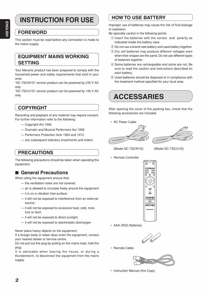
INSTRUCTION FOR USE HOW TO USE BATTERYImproper use of batteries may cause the risk of fluid leakageor explosion.Be specially careful in the following points.
q Insert the batteries with the correct and polarity asindicated inside the battery case.
w Do not use a brand-new battery and used battery together.
e Dry cell batteries may produce different voltages evenwhen their shapes are the same. Do not use different typesof batteries together.
r Some batteries are rechargeable and some are not. Besure to read the caution and instructions described oneach battery.
t Used batteries should be disposed of in compliance withthe treatment method specified for your local area.
FOREWORDThis section must be read before any connection is made tothe mains supply.
EQUIPMENT MAINS WORKINGSETTING
Your Marantz product has been prepared to comply with thehousehold power and safety requirements that exist in yourarea.“SC-7S2/N1G” version product can be powered by 230 V AConly.“SC-7S2/U1G” version product can be powered by 120 V AConly.
COPYRIGHTRecording and playback of any material may require consent.For further information refer to the following:
— Copyright Act 1956
— Dramatic and Musical Performers Act 1958
— Performers Protection Acts 1963 and 1972
— any subsequent statutory enactments and orders
PRECAUTIONSThe following precautions should be taken when operating theequipment.
7 General PrecautionsWhen siting the equipment ensure that:
— the ventilation holes are not covered;
— air is allowed to circulate freely around the equipment
— it is on a vibration free-surface;
— it will not be exposed to interference from an externalsource;
— it will not be exposed to excessive heat, cold, moisture or dust;
— it will not be exposed to direct sunlight;
— it will not be exposed to electrostatic discharges
Never place heavy objects on the equipment.If a foreign body or water does enter the equipment, contactyour nearest dealer or service centre.Do not pull out the plug by pulling on the mains lead, hold theplug.It is advisable when leaving the house, or during athunderstorm, to disconnect the equipment from the mainssupply.
ACCESSARIES
After opening the cover of the packing box, check that thefollowing accessories are included.
• AC Power Cable
(Model SC-7S2/N1G) (Model SC-7S2/U1G)
• Remote Controller
• AAA (R03) Batteries
• Remote Cable
• Instruction Manual (this Copy)
L
TRIM
FM/BAM/A
RETURNTOP MENU MENU
VOLUME
CLOSE MODE
PHONO CDBALANCED
RECORDER 1 LINE 1
RECORDER 2 LINE 2
EXIT TONE
ENTER
DISPLAY ATT
SCANRANDOM REPEAT
+
-
OPEN/ SOUND
R
SC-7S2 UN DFU 01 ENG 1/3 06.8.9, 1:52 PMPage 2 Adobe PageMaker 6.5J/PPC
EN
GL
ISH
3
MAIN FEATURE OF PRODUCT
7 The concept: channel separationfor super wide range & dynamicaudio
We think it’s of the utmost importance to extend high frequencyresponse as well as channel separation so you can hear thetrue meating of “Super Audio.”This is why we have designed the input and output circuitry,volume control section, and power supply circuits accordingto this philosophy.The result: an astonishing channel separation of over 100dBat 20kHz.
7 Fully balanced control amp withan linear volume control
The SC-7S2 is a full balanced, two-channel control ampproviding the channel separation you need for Super Audio.Based on our own high quality four-gang active volume controlwe have developed an even better linear control volume thatreduces gang errors from 0 to 100dB, ±0.5dB. By adding anadditional HDAM SA (Hyper Dynamic Amplifier Module), weimproved the Common Mode Reject Ratio (CMRR)dramatically, attaining an incredible ultra-wide frequency bandof 150kHz and succeeded in producing the perfect controlamplifier for Super Audio CD.
7 HDAM SAThe feedback impedance of the Current Feedback circuit wasreduced to its minimum to make it faster. We developed a newHyper Dynamic Amplifier Modules (HDAM), a separetedmodule operating as a buffer for the amplifier. The SC-7S2has four HDAM SA on each input-output buffer and anotherfour units on the V/I converter.
7 Choke input systemIn the power supply section, the choke input topology wasadopted to drastically reduce rectifier harmonic noise. Thissystem is especially suitable for a control amplifier in whichvery small signal amplification occurs.
7 Floating control bus systemWe make it possible to synchronously drive two or more controlamps by using a floating control bus system connected to asmany as 6 sets of control amplifiers. We also enable you totrim levels using the remote control, making it easy to set upthe optimal sound field on a multi-channel configuration. Thehighest achievable stereo performance can be accomplishedwhen a system configured with two sets of SC-7S2 and foursets of MA-9S2 are connected in a bi-amped mode.You will experience superb sound with unbelievable channelseparation.
SC-7S2 UN DFU 01 ENG 1/3 06.8.9, 1:52 PMPage 3 Adobe PageMaker 6.5J/PPC
EN
GL
ISH
4
MA-9S2
For L ch For R ch
MA-9S2
SC-7S2
POWER10
9
8
7
65
4
3
2
1
0
1 1
OUTPUTS
BALANCED
UNBALANCED
LEFTRIGHT ANALOG
INPUT OUTPUTANALOG
L
R
PUSH
PUSH
PUSH
PUSH
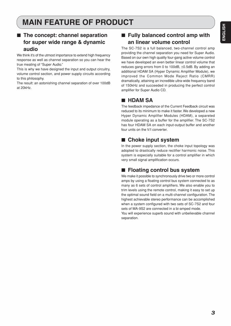
Setting 1
MODE
BI-AMPSTEREO
Setting STEREO
6
5
4
3
2
ID NO.ID NO.
1
or
Unbalanced connection
balanced connection
or
CD Player
CD Recorder / Tape Deck
:Signal flow
or
To connect analog output of FM tuner, DVD player.
CONNECTIONS
This connection can have options i.e. You may connect the units using either balanced or unbalanced cablesto connect your CD and control Amp, as well as the SC-7S2 with MA-9S2s. But you can not inter match.
Connection 1 Stereo connection
SC-7S2 UN DFU 01 ENG 1/3 06.8.9, 1:52 PMPage 4 Adobe PageMaker 6.5J/PPC
EN
GL
ISH
5
Connection 1–4 are recommended by Marantz for SC-7S2 with Marantz MA-9S2.If using the MA-9S2s, Please read the instruction manual for the MA-9S2.Name and Function P13
CONNECTIONS
Standard set-up in using Marantz Monaural Power Amp MA-9S2.Please refer to this connection in event of using other PowerAmps also.
• SC-7S2 doesn't have Phono equalizer. So in the event ofusing a turn table, please use a Phono equalizer to connectwith the SC-7S2.
• In event that stereo L ch signal has been wired with A chinput, the signal will come out of the pre-out of A ch. Pleasepay attention to L ch, R ch if SC-7S2 is connected with theother equipment.
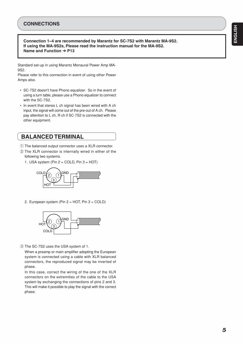
BALANCED TERMINAL
q The balanced output connector uses a XLR connector.
w The XLR connector is internally wired in either of thefollowing two systems.
1. USA system (Pin 2 = COLD, Pin 3 = HOT)
2. European system (Pin 2 = HOT, Pin 3 = COLD)
e The SC-7S2 uses the USA system of 1.
When a preamp or main amplifier adopting the Europeansystem is connected using a cable with XLR balancedconnectors, the reproduced signal may be inverted ofphase.
In this case, correct the wiring of the one of the XLRconnectors on the extremities of the cable to the USAsystem by exchanging the connections of pins 2 and 3.This will make it possible to play the signal with the correctphase.
2 13
HOT
GND
COLD
2 13
GNDCOLD
HOT
SC-7S2 UN DFU 01 ENG 1/3 06.8.9, 1:52 PMPage 5 Adobe PageMaker 6.5J/PPC
EN
GL
ISH
6
1 1
OUTPUTS
BALANCED
UNBALANCED
LEFTRIGHT ANALOG
INPUT OUTPUTANALOG
L
R
PUSH
PUSH
PUSH
PUSH
PUSH
PUSH
MA-9S2 MA-9S2
MA-9S2 MA-9S2
MODE
BI-AMPSTEREO
6
5
4
3
21
SC-7S2
For L ch For R ch
Setting STEREO
CD Player
CD Recorder / Tape Deck
For L ch MF/HF For R ch MF/HF
:Signal flow
Setting 1
To connect analog output of FM tuner, DVD player.
or
Unbalanced connection
balanced connection
POWER10
9
8
7
65
4
3
2
1
0
ID NO.ID NO.
CONNECTIONS
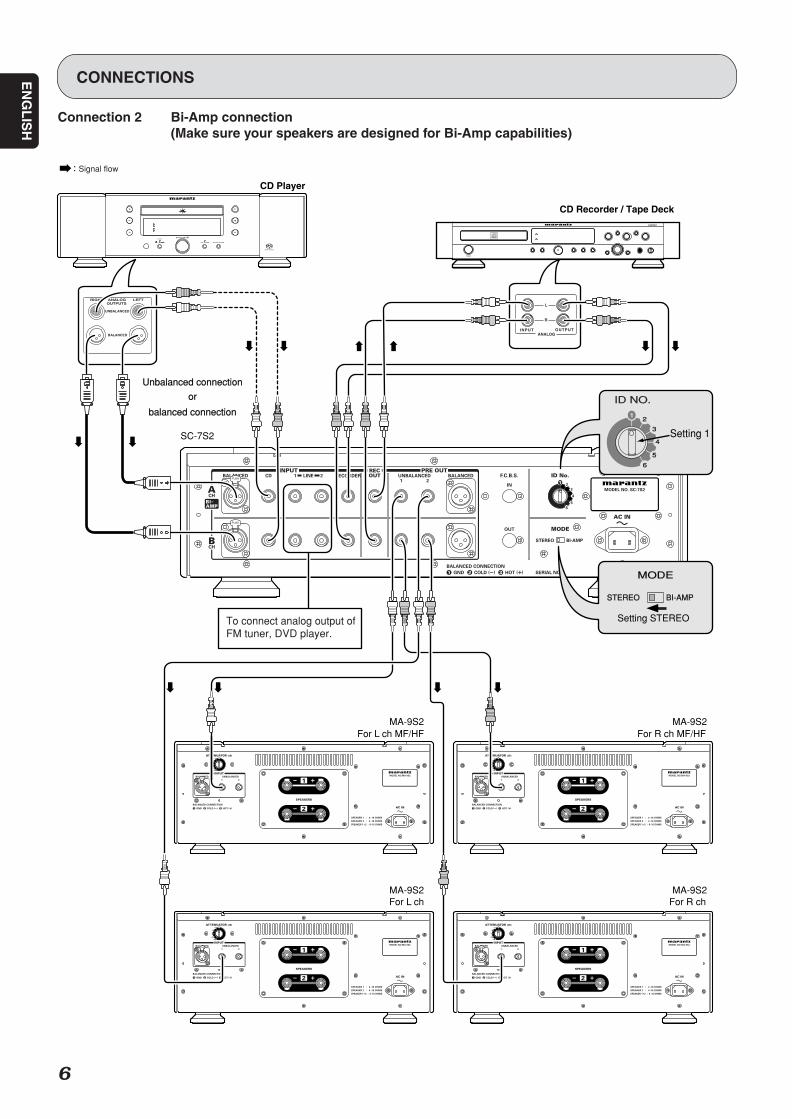
Connection 2 Bi-Amp connection(Make sure your speakers are designed for Bi-Amp capabilities)
SC-7S2 UN DFU 01 ENG 1/3 06.8.9, 1:52 PMPage 6 Adobe PageMaker 6.5J/PPC
EN
GL
ISH
7
This connection can have options i.e. You may connect the units using either balanced or unbalancedcables to connect your CD player and control Amp. But you can not inter match.Please select either way of connection.
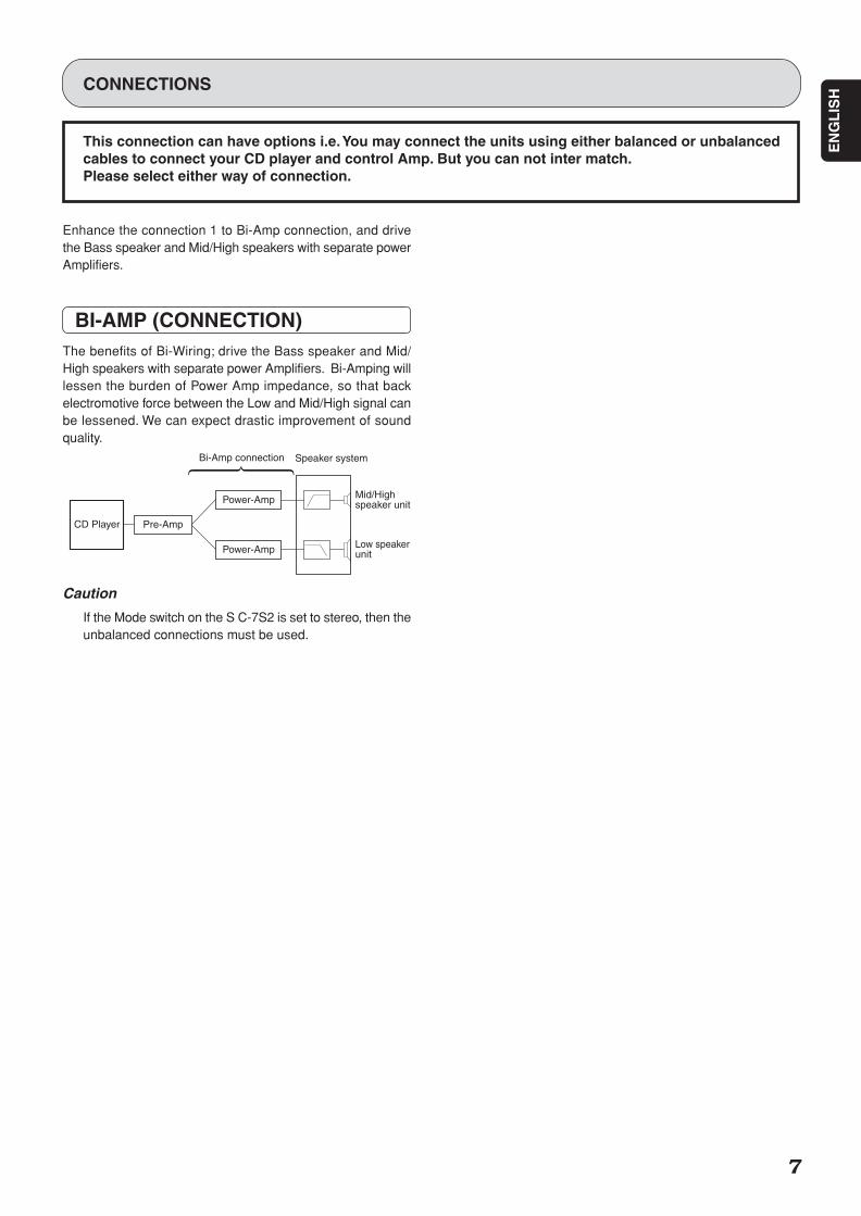
Enhance the connection 1 to Bi-Amp connection, and drivethe Bass speaker and Mid/High speakers with separate powerAmplifiers.
BI-AMP (CONNECTION)The benefits of Bi-Wiring; drive the Bass speaker and Mid/High speakers with separate power Amplifiers. Bi-Amping willlessen the burden of Power Amp impedance, so that backelectromotive force between the Low and Mid/High signal canbe lessened. We can expect drastic improvement of soundquality.
Caution
If the Mode switch on the S C-7S2 is set to stereo, then theunbalanced connections must be used.
CONNECTIONS
CD Player
Speaker system
Pre-Amp
Mid/Highspeaker unit
Low speakerunit
Power-Amp
Power-Amp
Bi-Amp connection
SC-7S2 UN DFU 01 ENG 1/3 06.8.9, 1:52 PMPage 7 Adobe PageMaker 6.5J/PPC
EN
GL
ISH
8
1 1
OUTPUTS
BALANCED
UNBALANCED
LEFTRIGHT ANALOG
INPUT OUTPUTANALOG
L
R
PUSH
PUSH
PUSH
PUSH
PUSH
PUSH
PUSH
PUSH
Setting 1
MODE
BI-AMPSTEREO
Setting BI-AMP
6
5
4
3
2
ID NO.ID NO.
1
6
5
4
3
2
ID NO.ID NO.
1
Setting 2
MODE
BI-AMPSTEREO
CD Player
CD Recorder / Tape Deck
For L chSC-7S2
FOR R chSC-7S2
POWER10
9
8
7
65
4
3
2
1
0
:Signal flow
oror
or or
or or
MA-9S2 MA-9S2
MA-9S2 MA-9S2 For L ch For R ch
For L ch MF/HF For R ch MF/HF
Setting BI-AMP
Bch can’t be used.
Bch can’t be used.
To connect analog output Lch of FM tuner, DVD player.
To connect analog output Rch of FM tuner, DVD player.
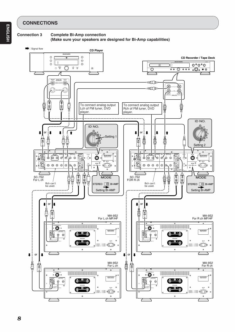
CONNECTIONS
Connection 3 Complete Bi-Amp connection(Make sure your speakers are designed for Bi-Amp capabilities)
SC-7S2 UN DFU 01 ENG 1/3 06.8.9, 1:52 PMPage 8 Adobe PageMaker 6.5J/PPC
EN
GL
ISH
9
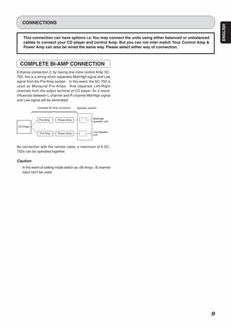
This connection can have options i.e. You may connect the units using either balanced or unbalancedcables to connect your CD player and control Amp. But you can not inter match. Your Control Amp &Power Amp can also be wired the same way. Please select either way of connection.
CONNECTIONS
COMPLETE BI-AMP CONNECTIONEnhance connection 2, by having one more control Amp. SC-7S2, this is a wiring which separates Mid/High signal and Lowsignal from the Pre-Amp section. In this event, the SC-7S2 isused as Monaural Pre-Amps. And separate Left/Rightchannels from the output terminal of CD player. As a result,influences between L channel and R channel Mid/High signaland Low signal will be eliminated.
By connection with the remote cable, a maximum of 6 SC-7S2s can be operated together.
Caution
In the event of setting mode switch as <Bi-Amp>, B channelinput can't be used.
CD Player
Pre-Amp
Speaker system
Pre-Amp
Power-Amp
Power-Amp
Complete Bi-Amp connection
Mid/Highspeaker unit
Low Speakerunit
SC-7S2 UN DFU 01 ENG 1/3 06.8.9, 1:52 PMPage 9 Adobe PageMaker 6.5J/PPC
EN
GL
ISH
10
CONNECTIONS
Centerspeaker
Rear speaker(Right Surround)
Sub-woofer
Front speaker(Left)
Rear speaker(Left Surround)
Front speaker(Right)
Reference listeningposition
approx. 110° approx. 110°
60°
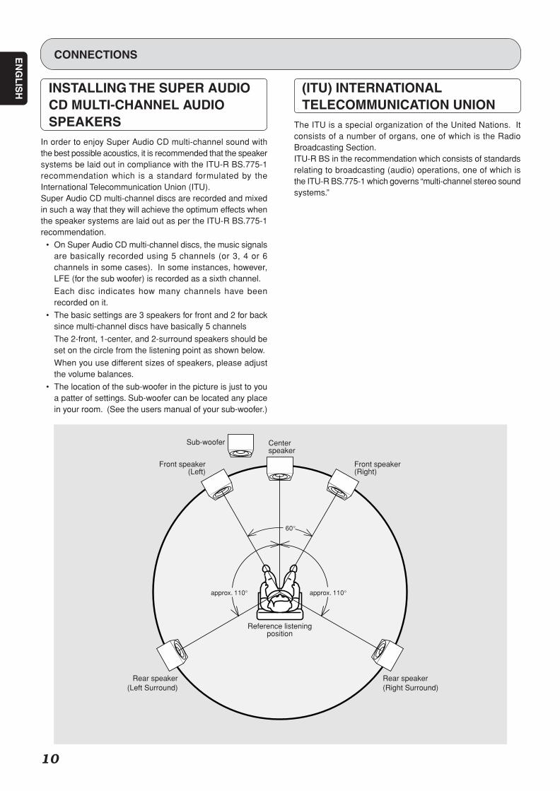
INSTALLING THE SUPER AUDIOCD MULTI-CHANNEL AUDIOSPEAKERS
In order to enjoy Super Audio CD multi-channel sound withthe best possible acoustics, it is recommended that the speakersystems be laid out in compliance with the ITU-R BS.775-1recommendation which is a standard formulated by theInternational Telecommunication Union (ITU).Super Audio CD multi-channel discs are recorded and mixedin such a way that they will achieve the optimum effects whenthe speaker systems are laid out as per the ITU-R BS.775-1recommendation.
• On Super Audio CD multi-channel discs, the music signalsare basically recorded using 5 channels (or 3, 4 or 6channels in some cases). In some instances, however,LFE (for the sub woofer) is recorded as a sixth channel.
Each disc indicates how many channels have beenrecorded on it.
• The basic settings are 3 speakers for front and 2 for backsince multi-channel discs have basically 5 channels
The 2-front, 1-center, and 2-surround speakers should beset on the circle from the listening point as shown below.
When you use different sizes of speakers, please adjustthe volume balances.
• The location of the sub-woofer in the picture is just to youa patter of settings. Sub-woofer can be located any placein your room. (See the users manual of your sub-woofer.)
(ITU) INTERNATIONALTELECOMMUNICATION UNION
The ITU is a special organization of the United Nations. Itconsists of a number of organs, one of which is the RadioBroadcasting Section.ITU-R BS in the recommendation which consists of standardsrelating to broadcasting (audio) operations, one of which isthe ITU-R BS.775-1 which governs “multi-channel stereo soundsystems.”
SC-7S2 UN DFU 01 ENG 1/3 06.8.9, 1:52 PMPage 10 Adobe PageMaker 6.5J/PPC
11
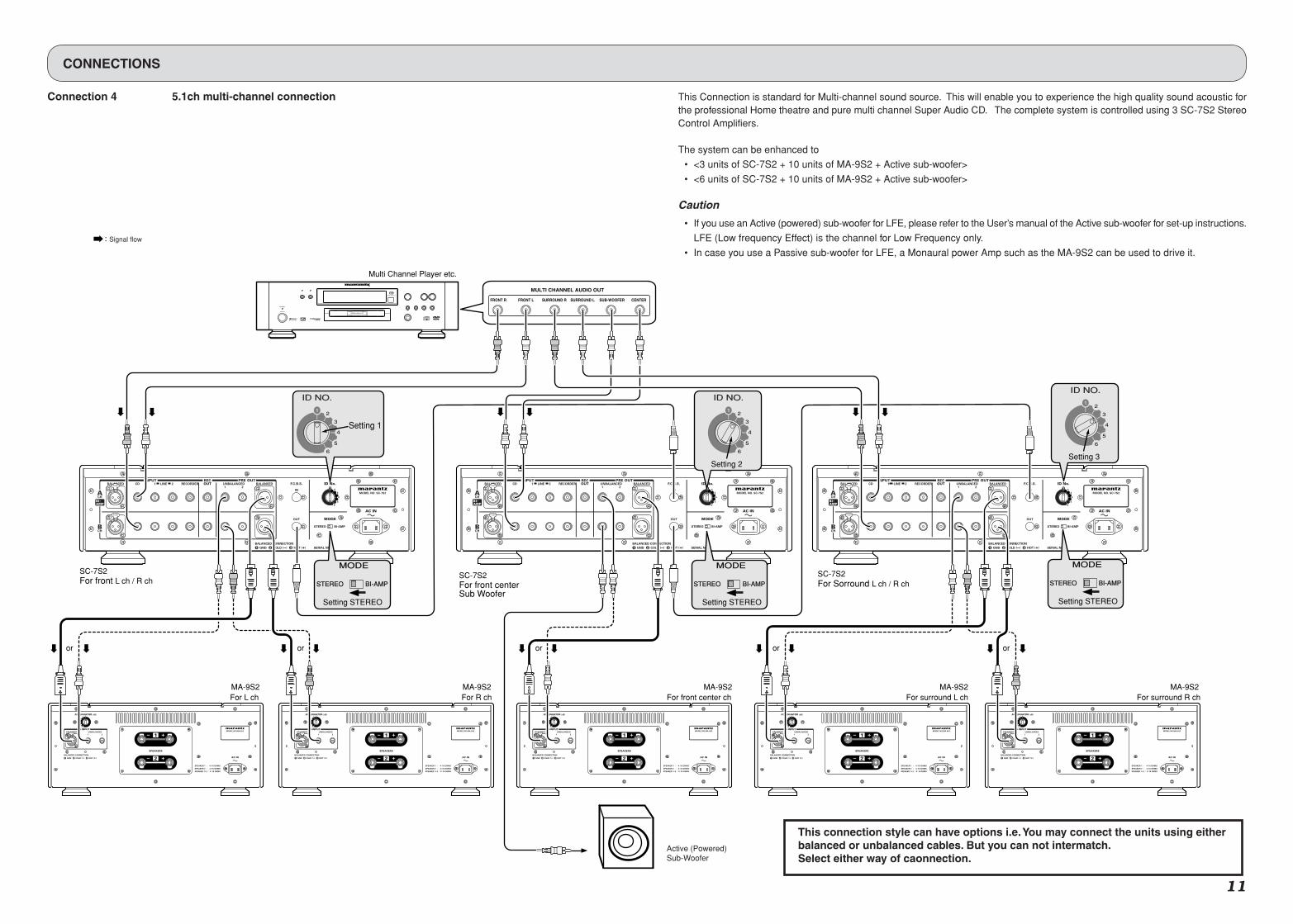
This Connection is standard for Multi-channel sound source. This will enable you to experience the high quality sound acoustic forthe professional Home theatre and pure multi channel Super Audio CD. The complete system is controlled using 3 SC-7S2 StereoControl Amplifiers.
The system can be enhanced to
• <3 units of SC-7S2 + 10 units of MA-9S2 + Active sub-woofer>
• <6 units of SC-7S2 + 10 units of MA-9S2 + Active sub-woofer>
Caution
• If you use an Active (powered) sub-woofer for LFE, please refer to the User’s manual of the Active sub-woofer for set-up instructions.
LFE (Low frequency Effect) is the channel for Low Frequency only.
• In case you use a Passive sub-woofer for LFE, a Monaural power Amp such as the MA-9S2 can be used to drive it.
POWER
STANDBY
For front L ch / R ch
MA-9S2 For L ch
For front centerSub Woofer
SC-7S2SC-7S2
For Sorround L ch / R chSC-7S2
FRONT R FRONT L SURROUND R SURROUND L SUB-WOOFER
MULTI CHANNEL AUDIO OUT
CENTER
MA-9S2 For R ch
MA-9S2 For front center ch
MA-9S2 For surround L ch
MA-9S2 For surround R ch
PUSH
PUSH
PUSH
PUSH
PUSH
PUSH
PUSH
PUSH
PUSH
PUSH
PUSH
MODE
Setting 1
6
5
4
3
2
ID NO.
1
BI-AMPSTEREO
Setting STEREO
MODE
BI-AMPSTEREO
Setting STEREO
MODE
BI-AMPSTEREO
Setting STEREO
6
5
4
3
2
ID NO.
1
Setting 36
5
4
3
2
ID NO.
1
Setting 2
ororor or
Active (Powered)Sub-Woofer
or
:Signal flow
Multi Channel Player etc.
This connection style can have options i.e. You may connect the units using eitherbalanced or unbalanced cables. But you can not intermatch.Select either way of caonnection.
CONNECTIONS
Connection 4 5.1ch multi-channel connection
SC-7S2 UN DFU 01 ENG 2/3 06.8.9, 1:52 PMPage 11 Adobe PageMaker 6.5J/PPC
12
NAME AND FUNCTION
BALANCED
CD
LINE 1
DISPLAY ATTLINE 2
RECORDER
A SYNC B
input selector
power on/of f
stereo control ampl i f ier sc-7s2
volume
q
r
uw y te
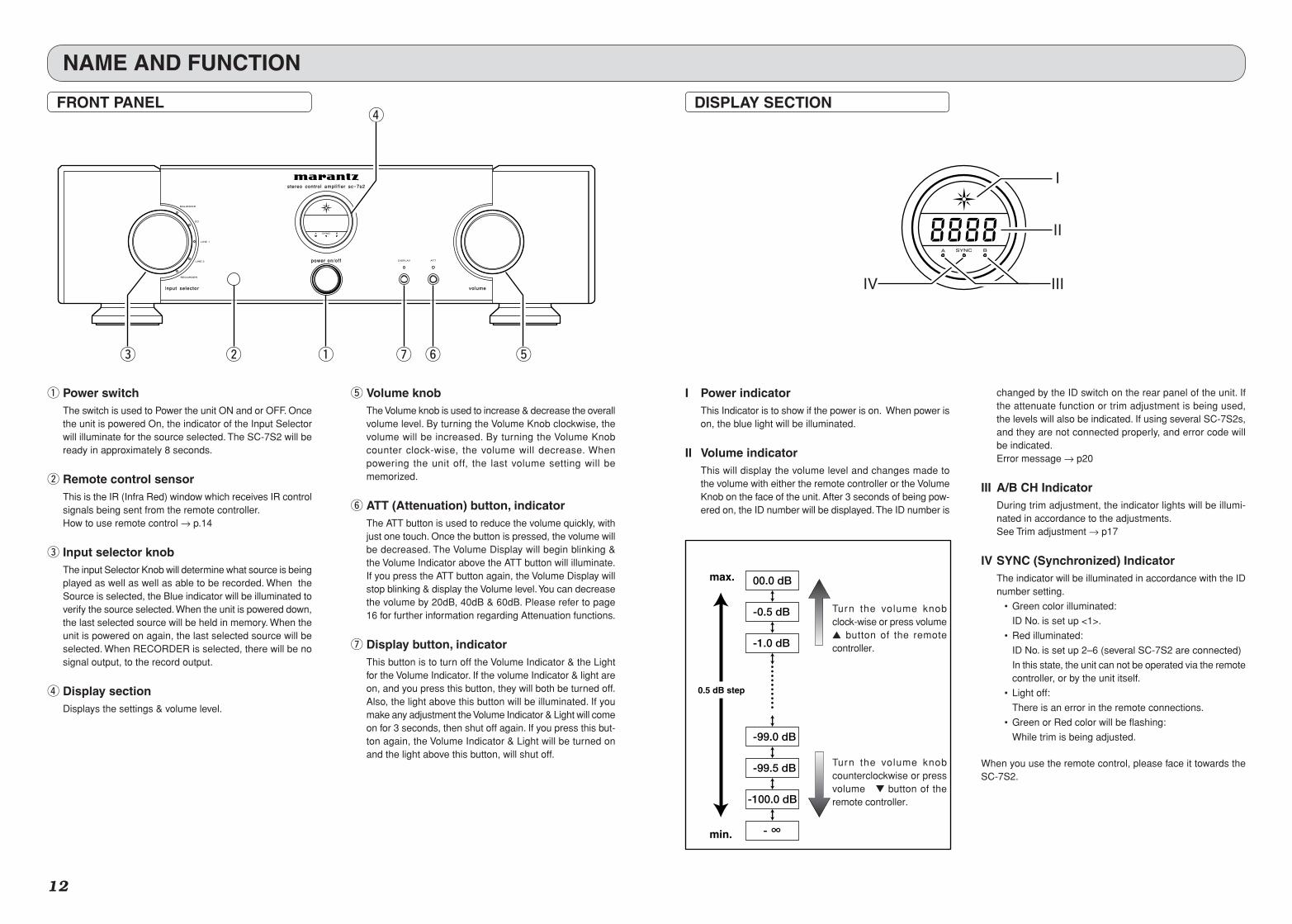
q Power switchThe switch is used to Power the unit ON and or OFF. Oncethe unit is powered On, the indicator of the Input Selectorwill illuminate for the source selected. The SC-7S2 will beready in approximately 8 seconds.
w Remote control sensorThis is the IR (Infra Red) window which receives IR controlsignals being sent from the remote controller.How to use remote control → p.14
e Input selector knobThe input Selector Knob will determine what source is beingplayed as well as well as able to be recorded. When theSource is selected, the Blue indicator will be illuminated toverify the source selected. When the unit is powered down,the last selected source will be held in memory. When theunit is powered on again, the last selected source will beselected. When RECORDER is selected, there will be nosignal output, to the record output.
r Display sectionDisplays the settings & volume level.
t Volume knobThe Volume knob is used to increase & decrease the overallvolume level. By turning the Volume Knob clockwise, thevolume will be increased. By turning the Volume Knobcounter clock-wise, the volume will decrease. Whenpowering the unit off, the last volume setting will bememorized.
y ATT (Attenuation) button, indicatorThe ATT button is used to reduce the volume quickly, withjust one touch. Once the button is pressed, the volume willbe decreased. The Volume Display will begin blinking &the Volume Indicator above the ATT button will illuminate.If you press the ATT button again, the Volume Display willstop blinking & display the Volume level. You can decreasethe volume by 20dB, 40dB & 60dB. Please refer to page16 for further information regarding Attenuation functions.
u Display button, indicatorThis button is to turn off the Volume Indicator & the Lightfor the Volume Indicator. If the volume Indicator & light areon, and you press this button, they will both be turned off.Also, the light above this button will be illuminated. If youmake any adjustment the Volume Indicator & Light will comeon for 3 seconds, then shut off again. If you press this but-ton again, the Volume Indicator & Light will be turned onand the light above this button, will shut off.
A SYNC B
I
II
IIIIV
DISPLAY SECTION
I Power indicatorThis Indicator is to show if the power is on. When power ison, the blue light will be illuminated.
II Volume indicatorThis will display the volume level and changes made tothe volume with either the remote controller or the VolumeKnob on the face of the unit. After 3 seconds of being pow-ered on, the ID number will be displayed. The ID number is
changed by the ID switch on the rear panel of the unit. Ifthe attenuate function or trim adjustment is being used,the levels will also be indicated. If using several SC-7S2s,and they are not connected properly, and error code willbe indicated.Error message → p20
III A/B CH IndicatorDuring trim adjustment, the indicator lights will be illumi-nated in accordance to the adjustments.See Trim adjustment → p17
IV SYNC (Synchronized) IndicatorThe indicator will be illuminated in accordance with the IDnumber setting.
• Green color illuminated:
ID No. is set up <1>.
• Red illuminated:
ID No. is set up 2–6 (several SC-7S2 are connected)
In this state, the unit can not be operated via the remotecontroller, or by the unit itself.
• Light off:
There is an error in the remote connections.
• Green or Red color will be flashing:
While trim is being adjusted.
When you use the remote control, please face it towards theSC-7S2.
max.
min.
00.0 dB
-0.5 dB
-1.0 dB
-99.0 dB
-99.5 dB
-100.0 dB
- ∞
0.5 dB step
Turn the volume knobclock-wise or press volume button of the remotecontroller.
Turn the volume knobcounterclockwise or pressvolume button of theremote controller.
FRONT PANEL
SC-7S2 UN DFU 01 ENG 2/3 06.8.9, 1:52 PMPage 12 Adobe PageMaker 6.5J/PPC
EN
GL
ISH
13
REAR PANEL
PUSH
PUSH
z bvc n , .mx
NAME AND FUNTION
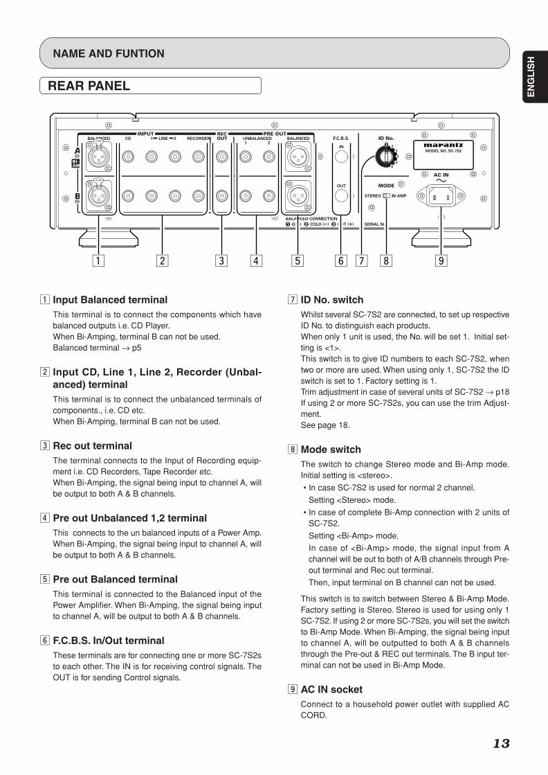
z Input Balanced terminalThis terminal is to connect the components which havebalanced outputs i.e. CD Player.When Bi-Amping, terminal B can not be used.Balanced terminal → p5
x Input CD, Line 1, Line 2, Recorder (Unbal-anced) terminalThis terminal is to connect the unbalanced terminals ofcomponents., i.e. CD etc.When Bi-Amping, terminal B can not be used.
c Rec out terminalThe terminal connects to the Input of Recording equip-ment i.e. CD Recorders, Tape Recorder etc.When Bi-Amping, the signal being input to channel A, willbe output to both A & B channels.
v Pre out Unbalanced 1,2 terminalThis connects to the un balanced inputs of a Power Amp.When Bi-Amping, the signal being input to channel A, willbe output to both A & B channels.
b Pre out Balanced terminalThis terminal is connected to the Balanced input of thePower Amplifier. When Bi-Amping, the signal being inputto channel A, will be output to both A & B channels.
n F.C.B.S. In/Out terminalThese terminals are for connecting one or more SC-7S2sto each other. The IN is for receiving control signals. TheOUT is for sending Control signals.
m ID No. switchWhilst several SC-7S2 are connected, to set up respectiveID No. to distinguish each products.When only 1 unit is used, the No. will be set 1. Initial set-ting is <1>.This switch is to give ID numbers to each SC-7S2, whentwo or more are used. When using only 1, SC-7S2 the IDswitch is set to 1. Factory setting is 1.Trim adjustment in case of several units of SC-7S2 → p18If using 2 or more SC-7S2s, you can use the trim Adjust-ment.See page 18.
, Mode switchThe switch to change Stereo mode and Bi-Amp mode.Initial setting is <stereo>.
• In case SC-7S2 is used for normal 2 channel.
Setting <Stereo> mode.
• In case of complete Bi-Amp connection with 2 units ofSC-7S2.
Setting <Bi-Amp> mode.
In case of <Bi-Amp> mode, the signal input from Achannel will be out to both of A/B channels through Pre-out terminal and Rec out terminal.
Then, input terminal on B channel can not be used.
This switch is to switch between Stereo & Bi-Amp Mode.Factory setting is Stereo. Stereo is used for using only 1SC-7S2. If using 2 or more SC-7S2s, you will set the switchto Bi-Amp Mode. When Bi-Amping, the signal being inputto channel A, will be outputted to both A & B channelsthrough the Pre-out & REC out terminals. The B input ter-minal can not be used in Bi-Amp Mode.
. AC IN socketConnect to a household power outlet with supplied ACCORD.
SC-7S2 UN DFU 01 ENG 3/3 06.8.9, 1:52 PMPage 13 Adobe PageMaker 6.5J/PPC
EN
GL
ISH
14
NAME AND FUNTION
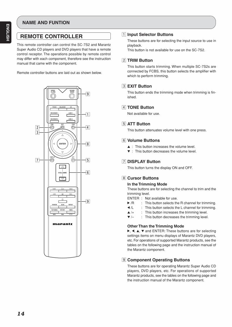
REMOTE CONTROLLERThis remote controller can control the SC-7S2 and MarantzSuper Audio CD players and DVD players that have a remotecontrol receptor. The operations possible by remote controlmay differ with each component, therefore see the instructionmanual that came with the component.
Remote controller buttons are laid out as shown below.
L
TRIM
FM/BAM/A
RETURNTOP MENU MENU
VOLUME
CLOSE MODE
PHONO CDBALANCED
RECORDER 1 LINE 1
RECORDER 2 LINE 2
EXIT TONE
ENTER
DISPLAY ATT
SCANRANDOM REPEAT
+
-
OPEN/ SOUND
R
z Input Selector ButtonsThese buttons are for selecting the input source to use inplayback.This button is not available for use on the SC-7S2.
x TRIM ButtonThis button starts trimming. When multiple SC-7S2s areconnected by FCBS, this button selects the amplifier withwhich to perform trimming.
c EXIT ButtonThis button ends the trimming mode when trimming is fin-ished.
v TONE ButtonNot available for use.
b ATT ButtonThis button attenuates volume level with one press.
n Volume Buttons3 : This button increases the volume level.4 : This button decreases the volume level.
m DISPLAY ButtonThis button turns the display ON and OFF.
, Cursor ButtonsIn the Trimming ModeThese buttons are for selecting the channel to trim and thetrimming level.ENTER : Not available for use.2 /R : This button selects the R channel for trimming.1 /L : This button selects the L channel for trimming.3 /+ : This button increases the trimming level.4 /– : This button decreases the trimming level.
Other Than the Trimming Mode2, 1, 3, 4 and ENTER: These buttons are for selectingsettings items on menu displays of Marantz DVD players,etc. For operations of supported Marantz products, see thetables on the following page and the instruction manual ofthe Marantz component.
. Component Operating ButtonsThese buttons are for operating Marantz Super Audio CDplayers, DVD players, etc. For operations of supportedMarantz products, see the tables on the following page andthe instruction manual of the Marantz component.
SC-7S2 UN DFU 01 ENG 3/3 06.8.9, 1:53 PMPage 14 Adobe PageMaker 6.5J/PPC
EN
GL
ISH
15
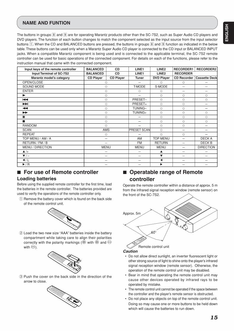
7 Operatable range of Remotecontroller
Operate the remote controller within a distance of approx. 5 mfrom the infrared signal reception window (remote sensor) onthe front of the SC-7S2.
Caution• Do not allow direct sunlight, an inverter fluorescent light or
other strong source of light to shine onto the player’s infraredsignal reception window (remote sensor). Otherwise, theoperation of the remote control unit may be disabled.
• Bear in mind that operating the remote control unit maycause other devices operated by infrared rays to beoperated by mistake.
• The remote control unit cannot be operated if the space betweenthe controller and the player’s remote sensor is obstructed.
• Do not place any objects on top of the remote control unit.
Doing so may cause one or more buttons to be held downwhich will cause the batteries to run down.
NAME AND FUNTION
The buttons in groups , and . are for operating Marantz products other than the SC-7S2, such as Super Audio CD players andDVD players. The function of each button changes to match the component selected as the input source from the input selectorbuttons z. When the CD and BALANCED buttons are pressed, the buttons in groups , and . function as indicated in the belowtable. These buttons can be used only when a Marantz Super Audio CD player is connected to the CD input or BALANCED INPUTjacks. When a compatible Marantz component is being used and is connected to the applicable terminal, the SC-7S2 remotecontroller can be used for basic operations of the connected component. For details on each of the functions, please refer to theinstruction manual that came with the connected component.
7 For use of Remote controllerLoading batteriesBefore using the supplied remote controller for the first time, loadthe batteries in the remote controller. The batteries provided areused to verify the operations of the remote controller only.
q Remove the battery cover which is found on the back sideof the remote control unit.
w Load the two new size “AAA” batteries inside the batterycompartment while taking care to align their polaritiescorrectly with the polarity markings ( with and with ).
e Push the cover on the back side in the direction of thearrow to close.
Approx. 5m
60°
Remote control unit
Input keys of the remote controller BALANCED CD LINE1 LINE2 RECORDER1 RECORDER2Input Terminal of SC-7S2 BALANCED CD LINE1 LINE2 RECORDERMarantz model’s category CD Player CD Player Tuner DVD Player CD Recorder Cassette Deck
OPEN/CLOSE ‡ --- ‡ ‡ ---SOUND MODE ‡ T-MODE S-MODE --- ---ENTER ‡ ‡ ‡ --- ---33333 ‡ --- ‡ ‡ ‡
44444 ‡ PRESET– ‡ ‡ ‡
¢¢¢¢¢ ‡ PRESET+ ‡ ‡ ---11111 ‡ TUNING– ‡ ‡ ---¡¡¡¡¡ ‡ TUNING+ ‡ ‡ ‡
88888 ‡ --- ‡ ‡ ‡
77777 ‡ --- ‡ ‡ ‡
RANDOM ‡ --- ‡ ‡ ---SCAN AMS PRESET SCAN ‡ --- ---REPEAT ‡ --- ‡ ‡ ---TOP MENU / AM / A --- AM TOP MENU --- DECK ARETURN / FM / B --- FM RETURN --- DECK BMENU / DIRECTION MENU MENU MENU --- DIRECTION3 /+ --- --- 3 --- ---4 / – --- --- 4 --- ---1 / L --- --- 1 --- ---2 / R --- --- 2 --- ---
SC-7S2 UN DFU 01 ENG 3/3 06.8.9, 1:53 PMPage 15 Adobe PageMaker 6.5J/PPC
EN
GL
ISH
16
L
TRIM
VOLUME
PHONO CDBALANCED
RECORDER 1 LINE 1
RECORDER 2 LINE 2
EXIT TONE
ENTER
DISPLAY ATT
+
-
R
w
et
BALANCEDBALANCED
CD
LINE 1
DISPLAYDISPLAY ATTLINE 2
RECORDERRECORDER
A SYNC B
input selector
power on/of f
stereo control ampl i f ier sc-7s2
volumevolume
q y e tw
L
TRIM
CLOSE MODE
PHONO CDBALANCED
RECORDER 1 LINE 1
RECORDER 2 LINE 2
EXIT TONE
ENTER
+
OPEN/ SOUND
R
w
BALANCEDBALANCED
CD
LINE 1
DISPLAYDISPLAY ATTLINE 2
RECORDERRECORDER
A SYNC B
input selector
power on/of f
stereo control ampl i f ier sc-7s2
volumevolume
qw
STANDARD OPERATION
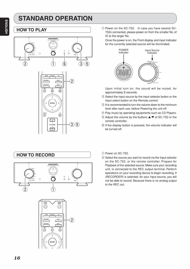
HOW TO PLAY q Power on the SC-7S2. In case you have several SC-7S2s connected, please power on from the smaller No. ofID to the larger No.
Once the power is on, the Front display and input indicatorfor the currently selected source will be illuminated.
A SYNC B
BALANCED
CD
LINE 1
LINE 2
RECORDER
POWERIndicator
Input SourceIndicator
Upon initial turn on, the sound will be muted, forapproximately 8 seconds.
w Select the input source by the input selector button or theInput select button on the Remote control.
e It is recommended to turn the volume down to the minimumlevel after each use, before Powering the unit off.
r Play music by operating equipments such as CD Players.
t Adjust the volume by the buttons / of SC-7S2 or theremote controller.
y If the display button is pressed, the volume indicator willbe turned off.
HOW TO RECORD q Power on SC-7S2.
w Select the source you want to record via the Input selectoron the SC-7S2, or the remote controller. Prepare forPlayback of the selected source. Make sure your recordingunit, is connected to the REC output terminal. Performoperations on your recording device to begin recording. If(RECORDER) is selected, for your input source, you willnot be able to record, Because there is no analog outputto the REC out.
SC-7S2 UN DFU 01 ENG 3/3 06.8.9, 1:53 PMPage 16 Adobe PageMaker 6.5J/PPC
EN
GL
ISH
17
HOW TO OPERATE FUNCTION AND HOW TO SET UP
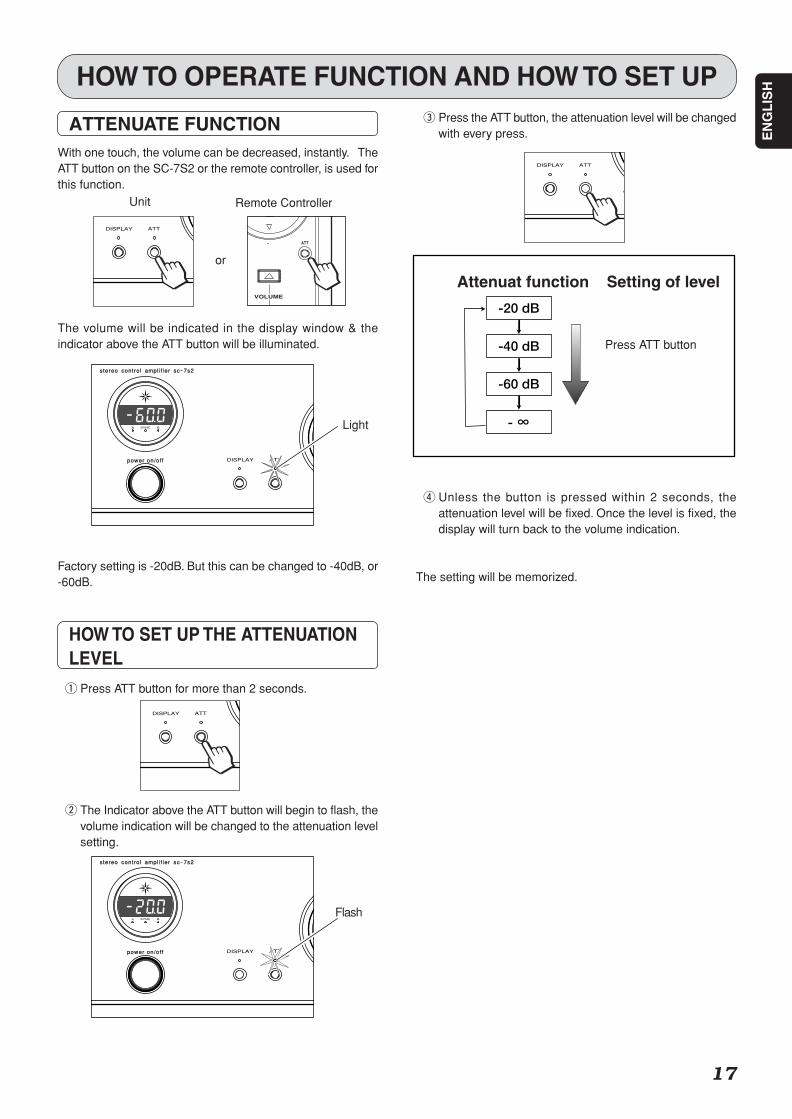
ATTENUATE FUNCTIONWith one touch, the volume can be decreased, instantly. TheATT button on the SC-7S2 or the remote controller, is used forthis function.
The volume will be indicated in the display window & theindicator above the ATT button will be illuminated.
Factory setting is -20dB. But this can be changed to -40dB, or-60dB.
HOW TO SET UP THE ATTENUATIONLEVEL
q Press ATT button for more than 2 seconds.
w The Indicator above the ATT button will begin to flash, thevolume indication will be changed to the attenuation levelsetting.
DISPLAY ATT
input selector
power
stereo control ampl i f ier sc-7s1
volume
VOLUME
ATT-
A SYNC B
DISPLAY ATT
input selector
power on/of f
stereo control ampl i f ier sc-7s2
volume
DISPLAY ATT
input selector
power
stereo control ampl i f ier sc-7s1
volume
A SYNC B
input selector
power on/of f
stereo control ampl i f ier sc-7s2
volume
DISPLAY ATT
e Press the ATT button, the attenuation level will be changedwith every press.
r Unless the button is pressed within 2 seconds, theattenuation level will be fixed. Once the level is fixed, thedisplay will turn back to the volume indication.
The setting will be memorized.
DISPLAY ATT
input selector
power
stereo control ampl i f ier sc-7s1
volume
-40 dB
-60 dB
- ∞
-20 dB
Press ATT button
Attenuat function Setting of level
Unit
or
Remote Controller
Light
Flash
SC-7S2 UN DFU 01 ENG 3/3 06.8.9, 1:53 PMPage 17 Adobe PageMaker 6.5J/PPC
EN
GL
ISH
18
HOW TO OPERATE FUNCTION AND HOW TO SET UP
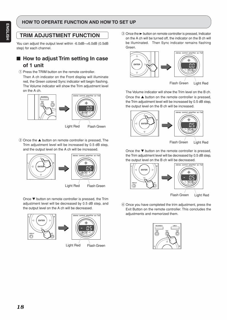
TRIM ADJUSTMENT FUNCTIONYou can adjust the output level within -6.0dB–+6.0dB (0.5dBstep) for each channel.
77777 How to adjust Trim setting In caseof 1 unit
q Press the TRIM button on the remote controller.
Then A ch indicator on the Front display will illuminatered, the Green colored Sync indicator will begin flashing.The Volume indicator will show the Trim adjustment levelon the A ch.
w Once the button on remote controller is pressed, TheTrim adjustment level will be increased by 0.5 dB step,and the output level on the A ch will be increased.
Once button on remote controller is pressed, the Trimadjustment level will be decreased by 0.5 dB step, andthe output level on the A ch will be decreased.
e Once the 3 button on remote controller is pressed, Indicatoron the A ch will be turned off, the indicator on the B ch willbe illuminated. Then Sync indicator remains flashingGreen.
The Volume indicator will show the Trim level on the B ch.
Once the button on the remote controller is pressed,the Trim adjustment level will be increased by 0.5 dB step,the output level on the B ch will be increased.
Once the button on the remote controller is pressed,the Trim adjustment level will be decreased by 0.5 dB step,the output level on the B ch will be decreased.
r Once you have completed the trim adjustment, press theExit Button on the remote controller. This concludes theadjustments and memorized them.
L
TRIM
RECORDER 2
EXIT
+
A SYNC B
input selector
power
stereo control ampl i f ier sc-7s2
volume
L
ENTER
DISPLAY ATT
+
R
A SYNC B
input selector
power
stereo control ampl i f ier sc-7s2
volume
L
ENTER
DISPLAY ATT-
R
A SYNC B
input selector
power
stereo control ampl i f ier sc-7s2
volume
ENTER
+
R
A SYNC B
input selector
power
stereo control ampl i f ier sc-7s2
volume
L
ENTER
DISPLAY ATT
+
R
A SYNC B
input selector
power
stereo control ampl i f ier sc-7s2
volume
L
ENTER
DISPLAY ATT-
R
A SYNC B
input selector
power
stereo control ampl i f ier sc-7s2
volume
L
TRIM
RECORDER 2 LINE 2
EXIT TONE
+
R
Light RedFlash Green
Light RedFlash Green
Light RedFlash Green
Flash GreenLight Red
Flash GreenLight Red
Flash GreenLight Red
SC-7S2 UN DFU 01 ENG 3/3 06.8.9, 1:53 PMPage 18 Adobe PageMaker 6.5J/PPC
EN
GL
ISH
19
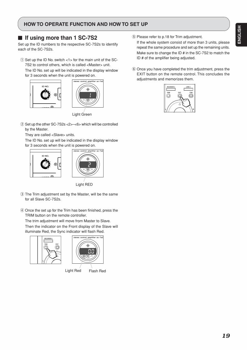
77777 If using more than 1 SC-7S2Set up the ID numbers to the respective SC-7S2s to identifyeach of the SC-7S2s.
q Set up the ID No. switch <1> for the main unit of the SC-7S2 to control others, which is called <Master> unit.
The ID No. set up will be indicated in the display windowfor 3 seconds when the unit is powered on.
w Set up the other SC-7S2s <2>–<6> which will be controlledby the Master.
They are called <Slave> units.
The ID No. set up will be indicated in the display windowfor 3 seconds when the unit is powered on.
e The Trim adjustment set by the Master, will be the samefor all Slave SC-7S2s.
r Once the set up for the Trim has been finished, press theTRIM button on the remote controller.
The trim adjustment will move from Master to Slave.
Then the indicator on the Front display of the Slave willilluminate Red, the Sync indicator will flash Red.
HOW TO OPERATE FUNCTION AND HOW TO SET UP
t Please refer to p.18 for Trim adjustment.
If the whole system consist of more than 3 units, pleaserepeat the same procedure and set up the remaining units.
Make sure to change the ID # in the SC-7S2 to match theID # of the amplifier being adjusted.
y Once you have completed the trim adjustment, press theEXIT button on the remote control. This concludes theadjustments and memorizes them.
ID NO.ID NO.REMOTE
CONTROLPRE OUTINPUT
BALANCED
RECOUTTAPE1 LINE 2SACD/CDBALANCED
ABI-AMP
21UNBALANCED
IN
OUT MODE
BI-AMPSTEREO
1
6
5
4
3
2
AC IN
BALANCED CONNECTION 1 COLD 2 COLD(-) 3 HOT(+)
CH
BCH
A SYNC B
input selector
power
stereo control ampl i f ier sc-7s2
volume
ID NO.ID NO.REMOTE
CONTROLPRE OUTINPUT
BALANCED
RECOUTTAPE1 LINE 2SACD/CDBALANCED
ABI-AMP
21UNBALANCED
IN
OUT MODE
BI-AMPSTEREO
1
6
5
4
3
2
AC IN
BALANCED CONNECTION 1 COLD 2 COLD(-) 3 HOT(+)
CH
BCH
A SYNC B
input selector
power
stereo control ampl i f ier sc-7s2
volume
L
TRIM
RECORDER 2
EXIT
+
A SYNC B
input selector
power
stereo control ampl i f ier sc-7s2
volume
L
TRIM
RECORDER 2 LINE 2
EXIT TONE
+
R
Light Red Flash Red
Light RED
Light Green
SC-7S2 UN DFU 01 ENG 3/3 06.8.9, 1:53 PMPage 19 Adobe PageMaker 6.5J/PPC
EN
GL
ISH
20
BALANCED
CD
LINE 1
DISPLAY ATTLINE 2
RECORDER
A SYNC B
input selector
power on/of fpower on/of f
stereostereo control ampl i f ier sc-7s2
volumevolume
441
19
136
459
18
SPECIFICATION
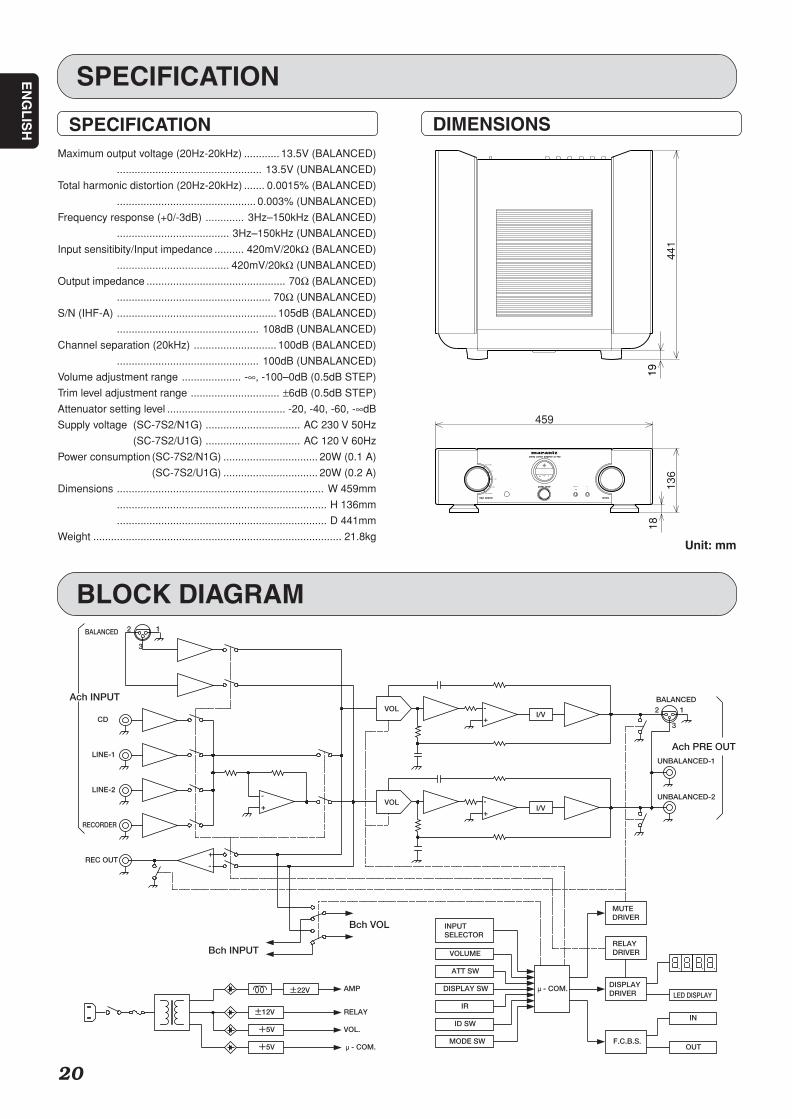
SPECIFICATIONMaximum output voltage (20Hz-20kHz) ............ 13.5V (BALANCED)
................................................. 13.5V (UNBALANCED)
Total harmonic distortion (20Hz-20kHz) ....... 0.0015% (BALANCED)
............................................... 0.003% (UNBALANCED)
Frequency response (+0/-3dB) ............. 3Hz–150kHz (BALANCED)
...................................... 3Hz–150kHz (UNBALANCED)
Input sensitibity/Input impedance .......... 420mV/20kΩ (BALANCED)
...................................... 420mV/20kΩ (UNBALANCED)
Output impedance ............................................... 70Ω (BALANCED)
.................................................... 70Ω (UNBALANCED)
S/N (IHF-A) ...................................................... 105dB (BALANCED)
................................................ 108dB (UNBALANCED)
Channel separation (20kHz) ............................ 100dB (BALANCED)
................................................ 100dB (UNBALANCED)
Volume adjustment range .................... -∞, -100–0dB (0.5dB STEP)
Trim level adjustment range .............................. ±6dB (0.5dB STEP)
Attenuator setting level ........................................ -20, -40, -60, -∞dB
Supply voltage (SC-7S2/N1G) ................................ AC 230 V 50Hz
(SC-7S2/U1G) ................................ AC 120 V 60Hz
Power consumption (SC-7S2/N1G) ................................ 20W (0.1 A)
(SC-7S2/U1G) ................................ 20W (0.2 A)
Dimensions ...................................................................... W 459mm
....................................................................... H 136mm
....................................................................... D 441mm
Weight .................................................................................... 21.8kg
DIMENSIONS
12
3
BALANCED
CD
LINE-1
LINE-2
RECORDER
REC OUT
12
3
BALANCED
UNBALANCED-1
UNBALANCED-2
Ach INPUT
±22V
+5V
±12V
AMP
RELAY
LED DISPLAY
F.C.B.S.
DISPLAYDRIVER
IN
OUT
VOLUME
DISPLAY SW
ATT SW
IR
ID SW
I/VVOL
I/VVOL
+5V
VOL.
-
+
+
-
+
-
+
-
μ- COM.
INPUTSELECTOR
MODE SW
μ- COM.
MUTEDRIVER
RELAYDRIVER
Ach PRE OUT
Bch INPUT
Bch VOL
Unit: mm
BLOCK DIAGRAM
SC-7S2 UN DFU 01 ENG 3/3 06.8.9, 1:53 PMPage 20 Adobe PageMaker 6.5J/PPC
EN
GL
ISH
21
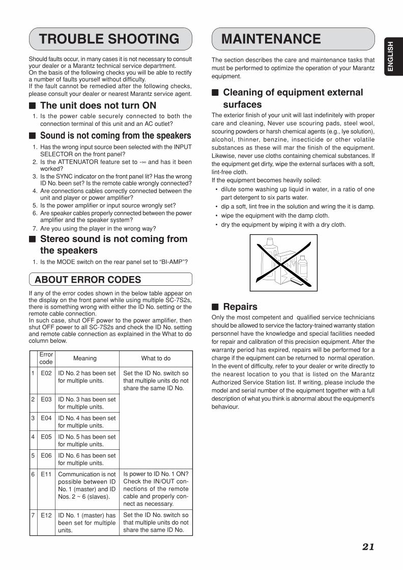
Should faults occur, in many cases it is not necessary to consultyour dealer or a Marantz technical service department.On the basis of the following checks you will be able to rectifya number of faults yourself without difficulty.If the fault cannot be remedied after the following checks,please consult your dealer or nearest Marantz service agent.
77777 The unit does not turn ON1. Is the power cable securely connected to both the
connection terminal of this unit and an AC outlet?
77777 Sound is not coming from the speakers1. Has the wrong input source been selected with the INPUT
SELECTOR on the front panel?2. Is the ATTENUATOR feature set to -∞ and has it been
worked?3. Is the SYNC indicator on the front panel lit? Has the wrong
ID No. been set? Is the remote cable wrongly connected?4. Are connections cables correctly connected between the
unit and player or power amplifier?5. Is the power amplifier or input source wrongly set?6. Are speaker cables properly connected between the power
amplifier and the speaker system?7. Are you using the player in the wrong way?
77777 Stereo sound is not coming fromthe speakers
1. Is the MODE switch on the rear panel set to “BI-AMP”?
ABOUT ERROR CODESIf any of the error codes shown in the below table appear onthe display on the front panel while using multiple SC-7S2s,there is something wrong with either the ID No. setting or theremote cable connection.In such case, shut OFF power to the power amplifier, thenshut OFF power to all SC-7S2s and check the ID No. settingand remote cable connection as explained in the What to docolumn below.
TROUBLE SHOOTINGThe section describes the care and maintenance tasks thatmust be performed to optimize the operation of your Marantzequipment.
77777 Cleaning of equipment externalsurfaces
The exterior finish of your unit will last indefinitely with propercare and cleaning, Never use scouring pads, steel wool,scouring powders or harsh chemical agents (e.g., lye solution),alcohol, thinner, benzine, insecticide or other volatilesubstances as these will mar the finish of the equipment.Likewise, never use cloths containing chemical substances. Ifthe equipment get dirty, wipe the external surfaces with a soft,lint-free cloth.If the equipment becomes heavily soiled:
• dilute some washing up liquid in water, in a ratio of onepart detergent to six parts water.
• dip a soft, lint free in the solution and wring the it is damp.
• wipe the equipment with the damp cloth.
• dry the equipment by wiping it with a dry cloth.
77777 RepairsOnly the most competent and qualified service techniciansshould be allowed to service the factory-trained warranty stationpersonnel have the knowledge and special facilities neededfor repair and calibration of this precision equipment. After thewarranty period has expired, repairs will be performed for acharge if the equipment can be returned to normal operation.In the event of difficulty, refer to your dealer or write directly tothe nearest location to you that is listed on the MarantzAuthorized Service Station list. If writing, please include themodel and serial number of the equipment together with a fulldescription of what you think is abnormal about the equipment'sbehaviour.
MAINTENANCE
Meaning
ID No. 2 has been setfor multiple units.
ID No. 3 has been setfor multiple units.
ID No. 4 has been setfor multiple units.
ID No. 5 has been setfor multiple units.
ID No. 6 has been setfor multiple units.
Communication is notpossible between IDNo. 1 (master) and IDNos. 2 ~ 6 (slaves).
ID No. 1 (master) hasbeen set for multipleunits.
What to do
Set the ID No. switch sothat multiple units do notshare the same ID No.
Is power to ID No. 1 ON?Check the IN/OUT con-nections of the remotecable and properly con-nect as necessary.
Set the ID No. switch sothat multiple units do notshare the same ID No.
Errorcode
1 E02
2 E03
3 E04
4 E05
5 E06
6 E11
7 E12
SC-7S2 UN DFU 01 ENG 3/3 06.8.9, 1:53 PMPage 21 Adobe PageMaker 6.5J/PPC

Printed in Japan 08/2006 00M340J851320 mzh-g
www.marantz.comYou can find your nearest authorized distributor or dealer on our website.
is a registered trademark.
SC-7S2 UN 00 Cover 06.8.9, 1:51 PMPage 4 Adobe PageMaker 6.5J/PPC


![7S2 - Zaklopka Za Zaštitu Od Požara, Cilindrična-Tip PPZ-C-K90[1]](https://img.pdfslide.net/doc/110x75/56d6bf781a28ab3016965e6d/7s2-zaklopka-za-zastitu-od-pozara-cilindricna-tip-ppz-c-k901.jpg)