Embed Size (px)
Citation preview

Model:
Table Top Orbital Shaker*
Operating and Maintenance ManualManual No: 7014518 Rev. 0
* Triple counter-balanced, single eccentric drive mechanism (U.S. Patent #5,558,437)
Model 4518 TT Orbital Shaker ____________________________________________________________________
i
Read This Instruction Manual.
Failure to read, understand and follow the instructions inthis manual may result in damage to the unit, injury to operat-ing personnel, and poor equipment performance.
CAUTION! All internal adjustments and maintenance mustbe performed by qualified service personnel.
Refer to the serial tag on the back of this manual.
The material in this manual is for information purposesonly. The contents and the product it describes are subject tochange without notice. Thermo Forma makes no representationsor warranties with respect to this manual. In no event shallThermo Forma be held liable for any damages, direct or inciden-tal, arising out of or related to the use of this manual.
MANUAL NO. 7014518
-- -- 12/29/98 Removed P/N 300311 from Section 1.1, per A. Campbell deg
- 17428 / OS-154 6/22/98 Added warning on ground to recorder outlet heg
- OS-136 7/31/97 Added pkg Sealview to packing list heg
- IN-2212 1/24/97 Patent notation added to cover heg
0 IN-2212 12/19/96 Added RJ-11 connector information heg
- - 1/24/97 Patent notation on cover deg
REV ECN DATE DESCRIPTION By
Contains Parts and AssembliesSusceptible to Damage by
Electrostatic Discharge (ESD)
CAUTION
The Model 4518 must be used to process non-flammable materials only!
Model 4518 TT Orbital Shaker ____________________________________________________________________
ii
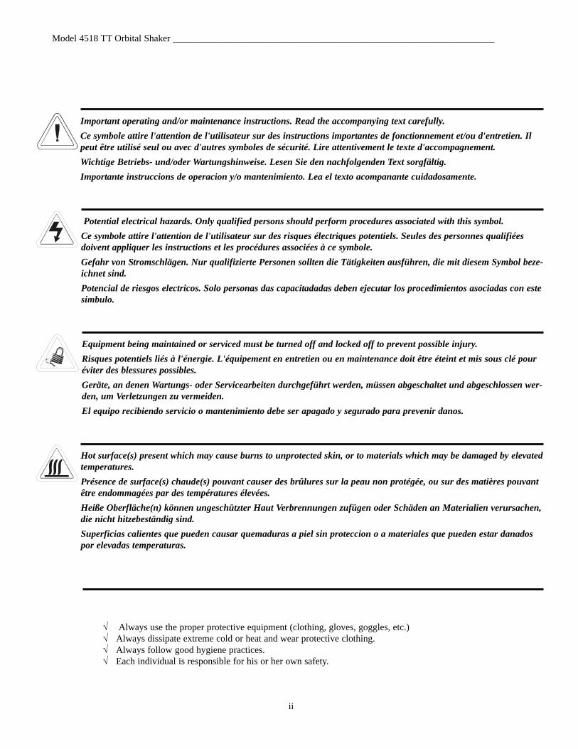
Important operating and/or maintenance instructions. Read the accompanying text carefully.Ce symbole attire l'attention de l'utilisateur sur des instructions importantes de fonctionnement et/ou d'entretien. Ilpeut être utilisé seul ou avec d'autres symboles de sécurité. Lire attentivement le texte d'accompagnement.Wichtige Betriebs- und/oder Wartungshinweise. Lesen Sie den nachfolgenden Text sorgfältig.Importante instruccions de operacion y/o mantenimiento. Lea el texto acompanante cuidadosamente.
Potential electrical hazards. Only qualified persons should perform procedures associated with this symbol.Ce symbole attire l'attention de l'utilisateur sur des risques électriques potentiels. Seules des personnes qualifiéesdoivent appliquer les instructions et les procédures associées à ce symbole.Gefahr von Stromschlägen. Nur qualifizierte Personen sollten die Tätigkeiten ausführen, die mit diesem Symbol beze-ichnet sind.Potencial de riesgos electricos. Solo personas das capacitadadas deben ejecutar los procedimientos asociadas con estesimbulo.
Equipment being maintained or serviced must be turned off and locked off to prevent possible injury.Risques potentiels liés à l'énergie. L'équipement en entretien ou en maintenance doit être éteint et mis sous clé pouréviter des blessures possibles.Geräte, an denen Wartungs- oder Servicearbeiten durchgeführt werden, müssen abgeschaltet und abgeschlossen wer-den, um Verletzungen zu vermeiden.El equipo recibiendo servicio o mantenimiento debe ser apagado y segurado para prevenir danos.
Hot surface(s) present which may cause burns to unprotected skin, or to materials which may be damaged by elevatedtemperatures.Présence de surface(s) chaude(s) pouvant causer des brûlures sur la peau non protégée, ou sur des matières pouvantêtre endommagées par des températures élevées.Heiße Oberfläche(n) können ungeschützter Haut Verbrennungen zufügen oder Schäden an Materialien verursachen,die nicht hitzebeständig sind.Superficias calientes que pueden causar quemaduras a piel sin proteccion o a materiales que pueden estar danadospor elevadas temperaturas.
√ Always use the proper protective equipment (clothing, gloves, goggles, etc.)√ Always dissipate extreme cold or heat and wear protective clothing.√ Always follow good hygiene practices.√ Each individual is responsible for his or her own safety.

Model 4518 TT Orbital Shaker ____________________________________________________________________
iii
Model 4518 TT Orbital Shaker ____________________________________________________________________
iv
Table of Contents
Section 1 - Receiving . . . . . . . . . . . . . . . . . . . . . . . . . . . .2 - 11.1 Preliminary Inspection . . . . . . . . . . . . . . . . . . . . . . . .2 - 11.2 Visible Loss or Damage . . . . . . . . . . . . . . . . . . . . . . .2 - 11.3 Responsibility for Shipping Damage . . . . . . . . . . . . .2 - 11.4 Packing List . . . . . . . . . . . . . . . . . . . . . . . . . . . . . . . .2 - 1
Section 2 - Installation . . . . . . . . . . . . . . . . . . . . . . . . . .2 - 12.1 Location . . . . . . . . . . . . . . . . . . . . . . . . . . . . . . . . . . .2 - 12.2 Removing the Pallet Shipping Brackets . . . . . . . . . . .2 - 12.3 Installing the Shaker Platform . . . . . . . . . . . . . . . . . .2 - 2
a. Removing Drive Mechanism Shipping Bracket . .2 - 2b. Installing the Platform . . . . . . . . . . . . . . . . . . . . . .2 - 2
2.4 Electrical Requirements . . . . . . . . . . . . . . . . . . . . . . .2 - 32.5 Assembling the Flask Clips . . . . . . . . . . . . . . . . . . . .2 - 32.6 Installing the Flask Clips . . . . . . . . . . . . . . . . . . . . . .2 - 32.7 Installing the Test Tube Holders . . . . . . . . . . . . . . . . .2 - 42.8 Test Tube Racks and Adjustable-Angle Rack Holder 2 - 42.9 The RS-232 Interface Connector . . . . . . . . . . . . . . . .2 - 52.10 Connecting the Remote Alarm . . . . . . . . . . . . . . . . .2 - 62.11 Lid Security Lock . . . . . . . . . . . . . . . . . . . . . . . . . . .2 - 62.12 Quick Reference Guide . . . . . . . . . . . . . . . . . . . . . . .2 - 6
Section 3 - Operation . . . . . . . . . . . . . . . . . . . . . . . . . . . .3 - 13.1 Introduction . . . . . . . . . . . . . . . . . . . . . . . . . . . . . . . . .3 - 13.2 Factory Settings . . . . . . . . . . . . . . . . . . . . . . . . . . . . .3 - 1
a. At Initial Start-Up . . . . . . . . . . . . . . . . . . . . . . . . .3 - 1b. Pre-set Programs . . . . . . . . . . . . . . . . . . . . . . . . . .3 - 2c. Other Factory Default Settings . . . . . . . . . . . . . . .3 - 2
3.3 Operating the Control Panel . . . . . . . . . . . . . . . . . . . .3 - 23.4 Quick Start Up . . . . . . . . . . . . . . . . . . . . . . . . . . . . . .3 - 23.5 Changing Time, Speed and Temperature Settings . . .3 - 3
a. Changing the Time setting . . . . . . . . . . . . . . . . . . .3 - 3b. Changing the RPM setting . . . . . . . . . . . . . . . . . . .3 - 3c. Changing the Temperature Setting . . . . . . . . . . . .3 - 3d. Hold Function - Setting to Count Elapsed Time .3 - 3
3.6 Operating the Shaker using Pre-Set Programs . . . . . .3 - 43.7 Making or Editing the Pre-Set Programs . . . . . . . . . .3 - 43.8 Changing/Setting the Access Code . . . . . . . . . . . . . . .3 - 43.9 Setting the Remote Alarms . . . . . . . . . . . . . . . . . . . . .3 - 43.10 Audible and Visual Alarms . . . . . . . . . . . . . . . . . . .3 - 4
a. Silencing the Audible Alarm . . . . . . . . . . . . . . . . .3 - 4b. Clearing the alarm display . . . . . . . . . . . . . . . . . . .3 - 4c. Over Temp Alarm and Over Temp Shutdown . . . .3 - 5d. Raising and Lowering Temp Alarms Setpoints . . .3 - 5
3.11 Turning the Audible Alarm Feature On or Off . . . .3 - 53.12 Reading the Accumulated Run Time . . . . . . . . . . . .3 - 53.13 Temperature Calibration . . . . . . . . . . . . . . . . . . . . .3 - 53.14 Reading the Over Temperature Probe . . . . . . . . . . . .3 - 53.15 Setting the Temperature Tracking Limit . . . . . . . . . .3 - 5
Section 4 - Maintenance . . . . . . . . . . . . . . . . . . . . . . . . .5 - 14.1 General Cleaning and Lubrication . . . . . . . . . . . . . . .5 - 1
a. Shaker Platform and Cabinet . . . . . . . . . . . . . . . . .5 - 1b. Control Panel . . . . . . . . . . . . . . . . . . . . . . . . . . . . .5 - 1
Section 5 - Service . . . . . . . . . . . . . . . . . . . . . . . . . . . . . .5 - 15.1 Alarms and Alarm Conditions . . . . . . . . . . . . . . . . . .5 - 15.3 Adjusting the Drive V-Belt Tension . . . . . . . . . . . . . .5 - 25.4 Installing a new Drive V-Belt . . . . . . . . . . . . . . . . . .5 - 25.5 Troubleshooting and replacing the Circuit Boards . . .5 - 3
a. Removing the Control Panel . . . . . . . . . . . . . . . . .5 - 3b. Main Circuit Board and Power Supply Tray . . . . .5 - 3c. Temperature Control Circuit Board . . . . . . . . . . . .5 - 4d. Microprocessor Circuit Board . . . . . . . . . . . . . . . .5 - 4e. Motor Driver Circuit Board . . . . . . . . . . . . . . . . . .5 - 5f. Manual Reset Safety Circuit Breaker . . . . . . . . . .5 - 6g. Temperature Sensors . . . . . . . . . . . . . . . . . . . . . . .5 - 6
Section 6 - Specifications . . . . . . . . . . . . . . . . . . . . . . . . .6 - 1
Section 7 - Parts List . . . . . . . . . . . . . . . . . . . . . . . . . . . .7 - 1
Section 8 - Electrical Schematics . . . . . . . . . . . . . . . . . .8 - 1
Model 4518 TT Orbital Shaker _________________________________________________________Receiving / Installation
2 - 1
Section 1 - Receiving
1.1 Preliminary Inspection
This item was thoroughly inspected and carefully packedprior to shipment and all necessary precautions were taken toensure safe arrival. Immediately upon receipt, before the unit ismoved from the receiving area, carefully examine the shipmentfor loss or damage. Unpack the shipment and inspect both inte-rior and exterior for any in-transit damage.
1.2 Visible Loss or Damage
If any loss or damage is discovered, note any discrepancieson the delivery receipt and call the delivering carrier andrequest that their representative perform an inspection. Do notdiscard any of the packing material and do not move the ship-ment from the receiving area.
1.3 Responsibility for Shipping Damage
For products shipped F.O.B. Marietta, Ohio, the responsi-bility of Thermo Forma ends when the merchandise is loadedonto the carrier’s vehicle.
On F.O.B. Destination shipments, Thermo Forma’s and thecarrier’s responsibility ends when your Receiving Departmentpersonnel sign a free and clear delivery receipt.
Whenever possible, Thermo Forma will assist in settlingclaims for loss or in-transit damage.
1.4 Packing List
The Model 4518 Orbital Incubator Shaker is supplied withthe following materials:
2 - Keys for the lid lock (packaged and attached to the outside of the unit)
1 - T-handle 5/32” hex socket wrench2 - Platform alignment studs 1/4-201 - Shaker Platform 6 - Grade 8, 5/32” hex socket flat head screws (provided
with platform)1 - Screwdriver for flask clip installation and removal1 - Line cord1 - Instruction manual
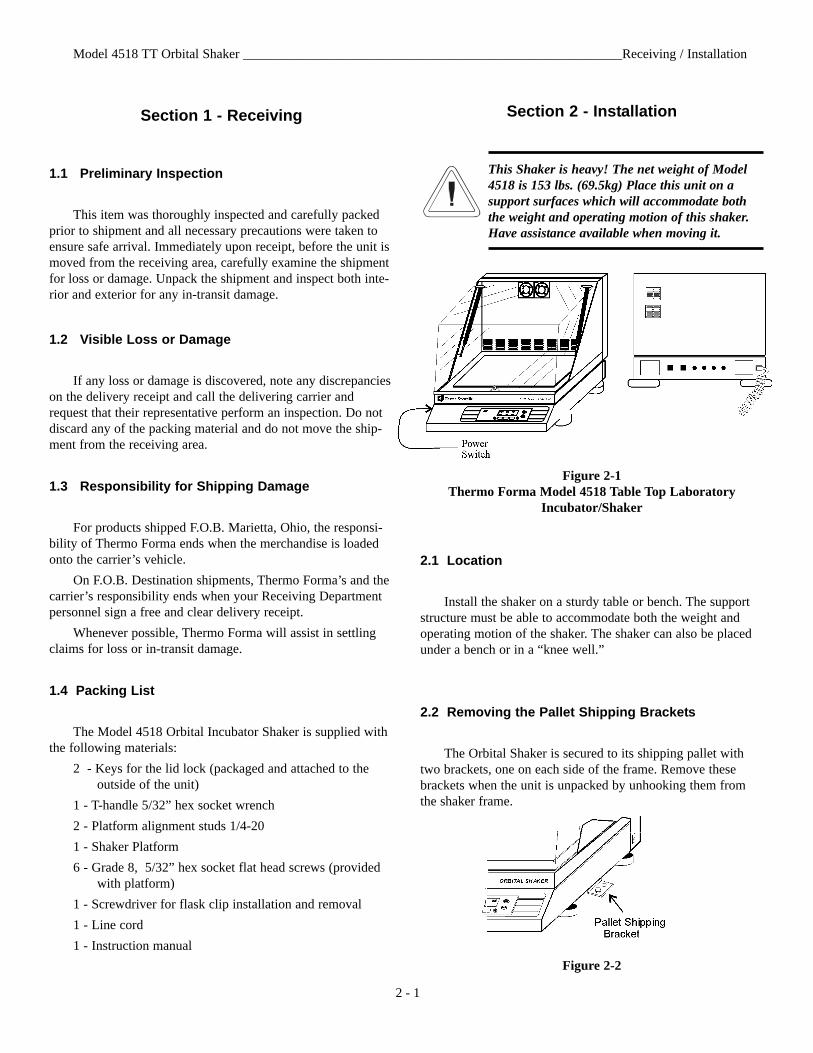
Section 2 - Installation
This Shaker is heavy! The net weight of Model4518 is 153 lbs. (69.5kg) Place this unit on asupport surfaces which will accommodate boththe weight and operating motion of this shaker.Have assistance available when moving it.
Figure 2-1Thermo Forma Model 4518 Table Top Laboratory
Incubator/Shaker
2.1 Location
Install the shaker on a sturdy table or bench. The supportstructure must be able to accommodate both the weight andoperating motion of the shaker. The shaker can also be placedunder a bench or in a “knee well.”
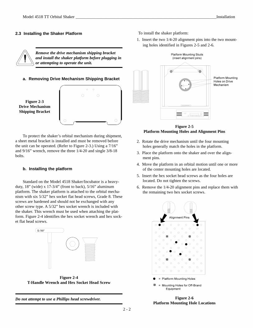
2.2 Removing the Pallet Shipping Brackets
The Orbital Shaker is secured to its shipping pallet withtwo brackets, one on each side of the frame. Remove thesebrackets when the unit is unpacked by unhooking them fromthe shaker frame.
Figure 2-2
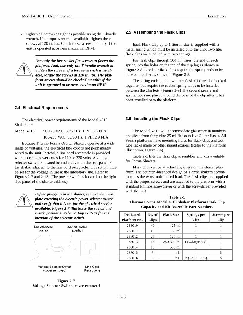
2.3 Installing the Shaker Platform
Remove the drive mechanism shipping bracketand install the shaker platform before plugging inor attempting to operate the unit.
a. Removing Drive Mechanism Shipping Bracket
Figure 2-3Drive MechanismShipping Bracket
To protect the shaker’s orbital mechanism during shipment,a sheet metal bracket is installed and must be removed beforethe unit can be operated. (Refer to Figure 2-3.) Using a 7/16”and 9/16” wrench, remove the three 1/4-20 and single 3/8-18bolts.
b. Installing the platform
Standard on the Model 4518 Shaker/Incubator is a heavy-duty, 18” (wide) x 17-3/4” (front to back), 5/16” aluminumplatform. The shaker platform is attached to the orbital mecha-nism with six 5/32” hex socket flat head screws, Grade 8. Thesescrews are hardened and should not be exchanged with anyother screw type. A 5/32” hex socket wrench is included withthe shaker. This wrench must be used when attaching the plat-form. Figure 2-4 identifies the hex socket wrench and hex sock-et flat head screws.
Figure 2-4T-Handle Wrench and Hex Socket Head Screw
Do not attempt to use a Phillips head screwdriver.
Model 4518 TT Orbital Shaker ____________________________________________________________________Installation
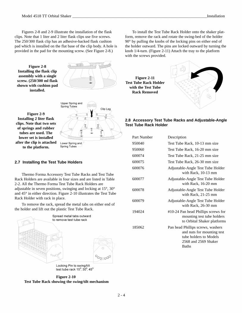
To install the shaker platform:1. Insert the two 1/4-20 alignment pins into the two mount-
ing holes identified in Figures 2-5 and 2-6.
Figure 2-5Platform Mounting Holes and Alignment Pins
2. Rotate the drive mechanism until the four mountingholes generally match the holes in the platform.
3. Place the platform onto the shaker and over the align-ment pins.
4. Move the platform in an orbital motion until one or moreof the center mounting holes are located.
5. Insert the hex socket head screws as the four holes arelocated. Do not tighten the screws.
6. Remove the 1/4-20 alignment pins and replace them withthe remaining two hex socket screws.
Figure 2-6Platform Mounting Hole Locations
2 - 2
7. Tighten all screws as tight as possible using the T-handlewrench. If a torque wrench is available, tighten thesescrews at 120 in. lbs. Check these screws monthly if theunit is operated at or near maximum RPM.
Use only the hex socket flat screws to fasten theplatform. And, use only the T-handle wrench totighten the screws. If a torque wrench is avail-able, torque the screws at 120 in. lbs. The plat-form screws should be checked monthly if theunit is operated at or near maximum RPM.
2.4 Electrical Requirements
The electrical power requirements of the Model 4518Shaker are:Model 4518 90-125 VAC, 50/60 Hz, 1 PH, 5.6 FLA
180-250 VAC, 50/60 Hz, 1 PH, 2.9 FLABecause Thermo Forma Orbital Shakers operate at a wide
range of voltages, the electrical line cord is not permanentlywired to the unit. Instead, a line cord receptacle is providedwhich accepts power cords for 110 or 220 volts. A voltageselector switch is located behind a cover on the rear panel ofthe shaker adjacent to the line cord receptacle. This switch mustbe set for the voltage in use at the laboratory site. Refer toFigures 2-7 and 2-13. (The power switch is located on the rightside panel of the shaker cabinet.)
Before plugging in the shaker, remove the metalplate covering the electric power selector switchand verify that it is set for the electrical serviceavailable. Figure 2-7 illustrates the switch andswitch positions. Refer to Figure 2-13 for thelocation of the selector switch.
Figure 2-7Voltage Selector Switch, cover removed
2.5 Assembling the Flask Clips
Each Flask Clip up to 1 liter in size is supplied with ametal spring which must be installed onto the clip. Two literflask clips are supplied with two springs.
For flask clips through 500 ml, insert the end of eachspring into the holes on the top of the clip leg as shown inFigure 2-8. One liter flask clips require the spring ends to behooked together as shown in Figure 2-9.
The spring ends on the two liter flask clip are also hookedtogether, but require the rubber spring tubes to be installedbetween the clip legs. (Figure 2-9) The second spring andspring tubes are placed around the base of the clip after it hasbeen installed onto the platform.
2.6 Installing the Flask Clips
The Model 4518 will accommodate glassware in numbersand sizes from forty-nine 25 ml flasks to five 2 liter flasks. AllForma platforms have mounting holes for flask clips and testtube racks made by other manufacturers (Refer to the Platformillustration, Figure 2-6).
Table 2-1 lists the flask clip assemblies and kits availablefor Forma Shakers.
Flask clips can be attached anywhere on the shaker plat-form. The counter -balanced design of Forma shakers accom-modates the worst unbalanced load. The flask clips are suppliedwith the proper screws and are attached to the platform with astandard Phillips screwdriver or with the screwdriver providedwith the unit.
Table 2-1Thermo Forma Model 4518 Shaker Platform Flask Clip
Capacity and Kit Assembly Part Numbers
Model 4518 TT Orbital Shaker ____________________________________________________________________Installation
2 - 3
Dedicated Platform No.
No. of Clips
Flask Size Springs per Clip
Screws per Clip
238010 49 25 ml 1 1 238011 49 50 ml 1 1 238012 25 125 ml 1 1 238013 18 250/300 ml 1 (w/large pad) 1 238014 16 500 ml 1 1 238015 8 1 L 1 5 238016 5 2 L 2 (w/10 tubes) 5
Figures 2-8 and 2-9 illustrate the installation of the flaskclips. Note that 1 liter and 2 liter flask clips use five screws.The 250/300 flask clip has an adhesive-backed flask cushionpad which is installed on the flat base of the clip body. A hole isprovided in the pad for the mounting screw. (See Figure 2-8.)
Figure 2-8Installing the flask clipassembly with a single
screw. (250/300 ml flaskshown with cushion pad
installed.
Figure 2-9 Installing 2 liter flask
clips. Note that two setsof springs and rubber
tubes are used. Thelower set is installed
after the clip is attachedto the platform.
2.7 Installing the Test Tube Holders
Thermo Forma Accessory Test Tube Racks and Test TubeRack Holders are available in four sizes and are listed in Table2-2. All the Thermo Forma Test Tube Rack Holders areadjustable in seven positions, swinging and locking at 15°, 30°and 45° in either direction. Figure 2-10 illustrates the Test TubeRack Holder with rack in place.
To remove the rack, spread the metal tabs on either end ofthe holder and lift out the plastic Test Tube Rack.
Figure 2-10Test Tube Rack showing the swing/tilt mechanism
To install the Test Tube Rack Holder onto the shaker plat-form, remove the rack and rotate the swing-bed of the holder90° by pulling the knobs of the locking pins on either end ofthe holder outward. The pins are locked outward by turning theknob 1/4-turn. (Figure 2-11) Attach the tray to the platformwith the screws provided.
Figure 2-11Test Tube Rack Holder
with the Test TubeRack Removed
2.8 Accessory Test Tube Racks and Adjustable-AngleTest Tube Rack Holder
Part Number Description950040 Test Tube Rack, 10-13 mm size950060 Test Tube Rack, 16-20 mm size600074 Test Tube Rack, 21-25 mm size600075 Test Tube Rack, 26-30 mm size600076 Adjustable-Angle Test Tube Holder
with Rack, 10-13 mm600077 Adjustable-Angle Test Tube Holder
with Rack, 16-20 mm600078 Adjustable-Angle Test Tube Holder
with Rack, 21-25 mm600079 Adjustable-Angle Test Tube Holder
with Rack, 26-30 mm194024 #10-24 Pan head Phillips screws for
mounting test tube holders to Orbital Shaker platforms
185062 Pan head Phillips screws, washers and nuts for mounting test tube holders to Models 2568 and 2569 Shaker Baths
Model 4518 TT Orbital Shaker ____________________________________________________________________Installation
2 - 4
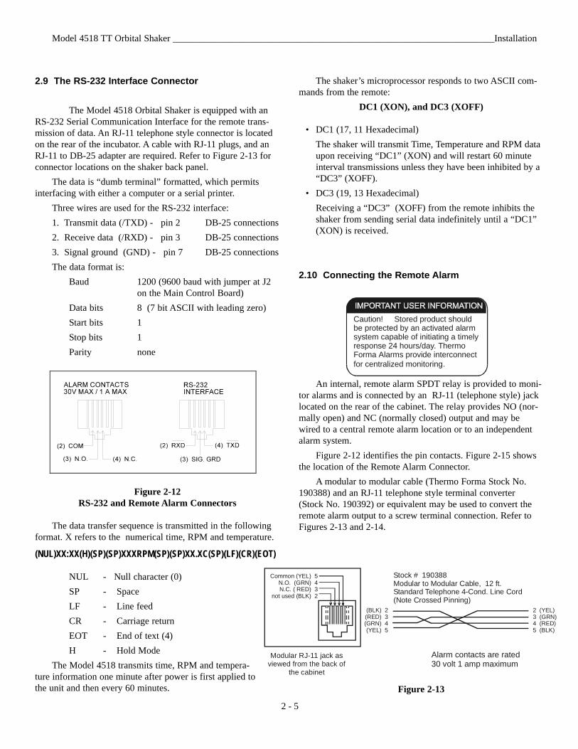
2.9 The RS-232 Interface Connector
The Model 4518 Orbital Shaker is equipped with anRS-232 Serial Communication Interface for the remote trans-mission of data. An RJ-11 telephone style connector is locatedon the rear of the incubator. A cable with RJ-11 plugs, and anRJ-11 to DB-25 adapter are required. Refer to Figure 2-13 forconnector locations on the shaker back panel.
The data is “dumb terminal” formatted, which permitsinterfacing with either a computer or a serial printer.
Three wires are used for the RS-232 interface:1. Transmit data (/TXD) - pin 2 DB-25 connections2. Receive data (/RXD) - pin 3 DB-25 connections3. Signal ground (GND) - pin 7 DB-25 connectionsThe data format is:
Baud 1200 (9600 baud with jumper at J2 on the Main Control Board)
Data bits 8 (7 bit ASCII with leading zero)Start bits 1Stop bits 1Parity none
Figure 2-12RS-232 and Remote Alarm Connectors
The data transfer sequence is transmitted in the followingformat. X refers to the numerical time, RPM and temperature.
(NUL)XX:XX(H)(SP)(SP)XXXRPM(SP)(SP)XX.XC(SP)(LF)(CR)(EOT)
NUL - Null character (0)SP - SpaceLF - Line feedCR - Carriage returnEOT - End of text (4)H - Hold Mode
The Model 4518 transmits time, RPM and tempera-ture information one minute after power is first applied tothe unit and then every 60 minutes.
The shaker’s microprocessor responds to two ASCII com-mands from the remote:
DC1 (XON), and DC3 (XOFF)
• DC1 (17, 11 Hexadecimal)The shaker will transmit Time, Temperature and RPM dataupon receiving “DC1” (XON) and will restart 60 minuteinterval transmissions unless they have been inhibited by a“DC3” (XOFF).
• DC3 (19, 13 Hexadecimal)Receiving a “DC3” (XOFF) from the remote inhibits theshaker from sending serial data indefinitely until a “DC1”(XON) is received.
2.10 Connecting the Remote Alarm
An internal, remote alarm SPDT relay is provided to moni-tor alarms and is connected by an RJ-11 (telephone style) jacklocated on the rear of the cabinet. The relay provides NO (nor-mally open) and NC (normally closed) output and may bewired to a central remote alarm location or to an independentalarm system.
Figure 2-12 identifies the pin contacts. Figure 2-15 showsthe location of the Remote Alarm Connector.
A modular to modular cable (Thermo Forma Stock No.190388) and an RJ-11 telephone style terminal converter(Stock No. 190392) or equivalent may be used to convert theremote alarm output to a screw terminal connection. Refer toFigures 2-13 and 2-14.
Figure 2-13
Model 4518 TT Orbital Shaker ____________________________________________________________________Installation
2 - 5
Caution! Stored product should be protected by an activated alarm system capable of initiating a timely response 24 hours/day. Thermo Forma Alarms provide interconnect for centralized monitoring.
Common (YEL) 5N.O. (GRN) 4N.C. ( RED) 3
not used (BLK) 2
(BLK) 2(RED) 3(GRN) 4(YEL) 5
2 (YEL)3 (GRN)4 (RED)5 (BLK)
Stock # 190388Modular to Modular Cable, 12 ft.Standard Telephone 4-Cond. Line Cord(Note Crossed Pinning)
Modular RJ-11 jack asviewed from the back of
the cabinet
Alarm contacts are rated30 volt 1 amp maximum
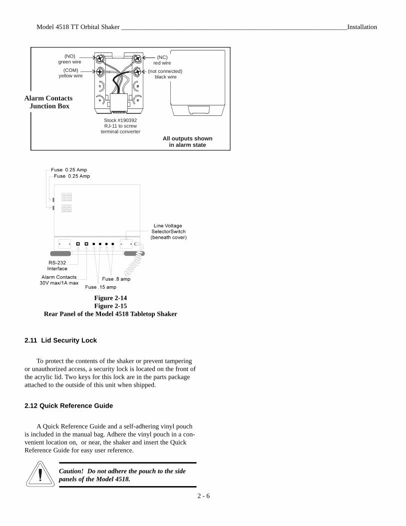
Figure 2-14Figure 2-15
Rear Panel of the Model 4518 Tabletop Shaker
2.11 Lid Security Lock
To protect the contents of the shaker or prevent tamperingor unauthorized access, a security lock is located on the front ofthe acrylic lid. Two keys for this lock are in the parts packageattached to the outside of this unit when shipped.
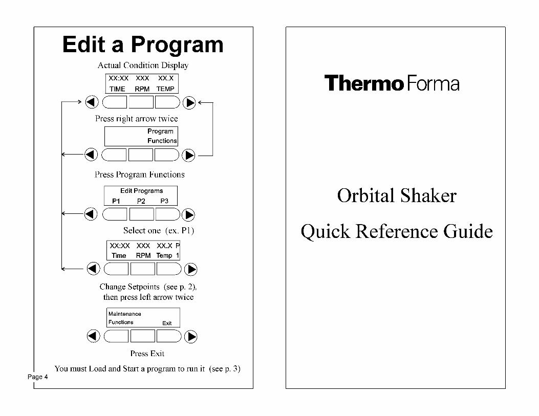
2.12 Quick Reference Guide
A Quick Reference Guide and a self-adhering vinyl pouchis included in the manual bag. Adhere the vinyl pouch in a con-venient location on, or near, the shaker and insert the QuickReference Guide for easy user reference.
Caution! Do not adhere the pouch to the sidepanels of the Model 4518.
Model 4518 TT Orbital Shaker ____________________________________________________________________Installation
2 - 6
(COM) yellow wire
(NO) green wire
Stock #190392RJ-11 to screw
terminal converter
Alarm Contacts Junction Box
All outputs shown in alarm state
(NC) red wire
(not connected) black wire
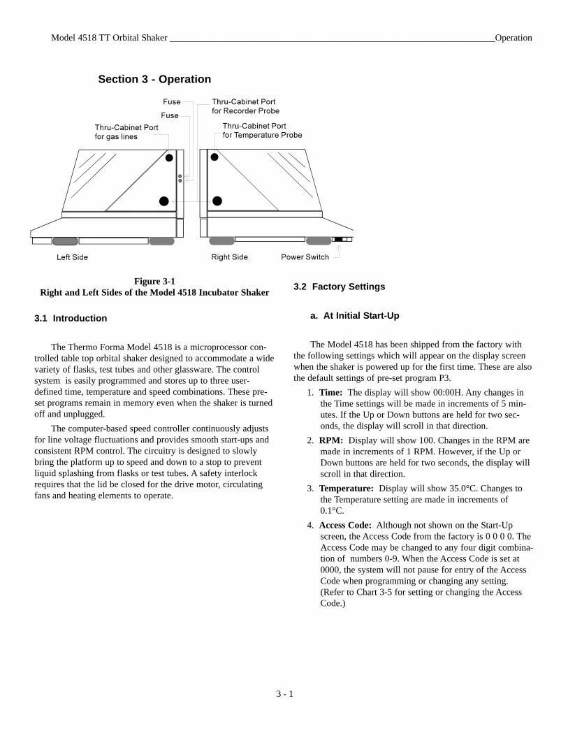
Section 3 - Operation
Figure 3-1Right and Left Sides of the Model 4518 Incubator Shaker
3.1 Introduction
The Thermo Forma Model 4518 is a microprocessor con-trolled table top orbital shaker designed to accommodate a widevariety of flasks, test tubes and other glassware. The controlsystem is easily programmed and stores up to three user-defined time, temperature and speed combinations. These pre-set programs remain in memory even when the shaker is turnedoff and unplugged.
The computer-based speed controller continuously adjustsfor line voltage fluctuations and provides smooth start-ups andconsistent RPM control. The circuitry is designed to slowlybring the platform up to speed and down to a stop to preventliquid splashing from flasks or test tubes. A safety interlockrequires that the lid be closed for the drive motor, circulatingfans and heating elements to operate.
3.2 Factory Settings
a. At Initial Start-Up
The Model 4518 has been shipped from the factory withthe following settings which will appear on the display screenwhen the shaker is powered up for the first time. These are alsothe default settings of pre-set program P3.
1. Time: The display will show 00:00H. Any changes inthe Time settings will be made in increments of 5 min-utes. If the Up or Down buttons are held for two sec-onds, the display will scroll in that direction.
2. RPM: Display will show 100. Changes in the RPM aremade in increments of 1 RPM. However, if the Up orDown buttons are held for two seconds, the display willscroll in that direction.
3. Temperature: Display will show 35.0°C. Changes tothe Temperature setting are made in increments of0.1°C.
4. Access Code: Although not shown on the Start-Upscreen, the Access Code from the factory is 0 0 0 0. TheAccess Code may be changed to any four digit combina-tion of numbers 0-9. When the Access Code is set at0000, the system will not pause for entry of the AccessCode when programming or changing any setting.(Refer to Chart 3-5 for setting or changing the AccessCode.)
Model 4518 TT Orbital Shaker ______________________________________________________________________Operation
3 - 1
b. Pre-set Programs
Three pre-set programs are stored into the shaker’s com-puter memory and may be used or edited at the operator’s dis-cretion. The operating parameters of Pre-set program P3 areactive (default) when the unit is turned on for the first time “outof the shipping box.” The values set by the factory for pre-setprograms P1, P2 and P3 are listed on the following page.
Instructions on operating the shaker using these pre-setprograms are found in Section 3.6. Instructions to edit theseprograms are in Section 3.7.
The microprocessor speed control system may takeup to one minute to bring platform up to speed.Never leave the shaker unattended when starting. Make sure all flasks and test tube racks are firmlyseated in the clips and check the security of flaskclips and platform attachment screws monthly.The lid must be closed to operate the shaker.Do not operate the shaker at maximum RPM with-out a load.
P1Time: 720 minutes (12 hours) Countdown ModeRPM: 250Temp: 35°C
P2Time: 1200 minutes (20 hours) Countdown ModeRPM: 300Temp: 28°C
P3Time: 00:00H Hold Time (accumulated) ModeRPM: 100Temp: 35°C
c. Other factory default settings
Function Default Reference Manual Section
Audible Alarm ON 3.8Access Code 0 0 0 0 3.10RPM Tracking Limit 5 3.11Temperature Tracking Limit 10°C 3.14Over Temperature Shut-down 63°C - 65°C 3.12.cAll Remote Alarms ON 3.11
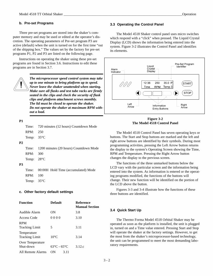
3.3 Operating the Control Panel
The Model 4518 Shaker control panel uses micro switcheswhich respond with a “click” when pressed. The Liquid CrystalDisplay (LCD) shows the information being entered into thesystem. Figure 3-2 illustrates the Control Panel and identifiesits elements.
Figure 3-2The Model 4518 Control Panel
The Model 4518 Control Panel has seven operating keys orbuttons. The Start and Stop buttons are marked and the left andright arrow buttons are identified by their symbols. During mostprogramming activities, pressing the Left Arrow button returnsthe display to the system’s Operating Screen showing the Time,RPM and Temperature. Pressing the Right Arrow buttonchanges the display to the previous screen.
The functions of the three unmarked buttons below theLCD vary with the particular screen and the information beingentered into the system. As information is entered or the operat-ing programs modified, the functions of the buttons willchange. Their new function will be identified on the portion ofthe LCD above the button.
Figures 3-3 and 3-4 illustrate how the functions of thesethree buttons are identified.
3.4 Quick Start Up
The Thermo Forma Model 4518 Orbital Shaker may beoperated as soon as the platform is installed, the unit is pluggedin, turned on and a Time value entered. Pressing Start and Stopwill operate the shaker at the factory settings. However, to getthe most from the shaker’s microprocessor-based technology,the unit can be programmed to meet the most demanding labo-ratory requirements.
Model 4518 TT Orbital Shaker ____________________________________________________________________Operation
3 - 2
3 - 3
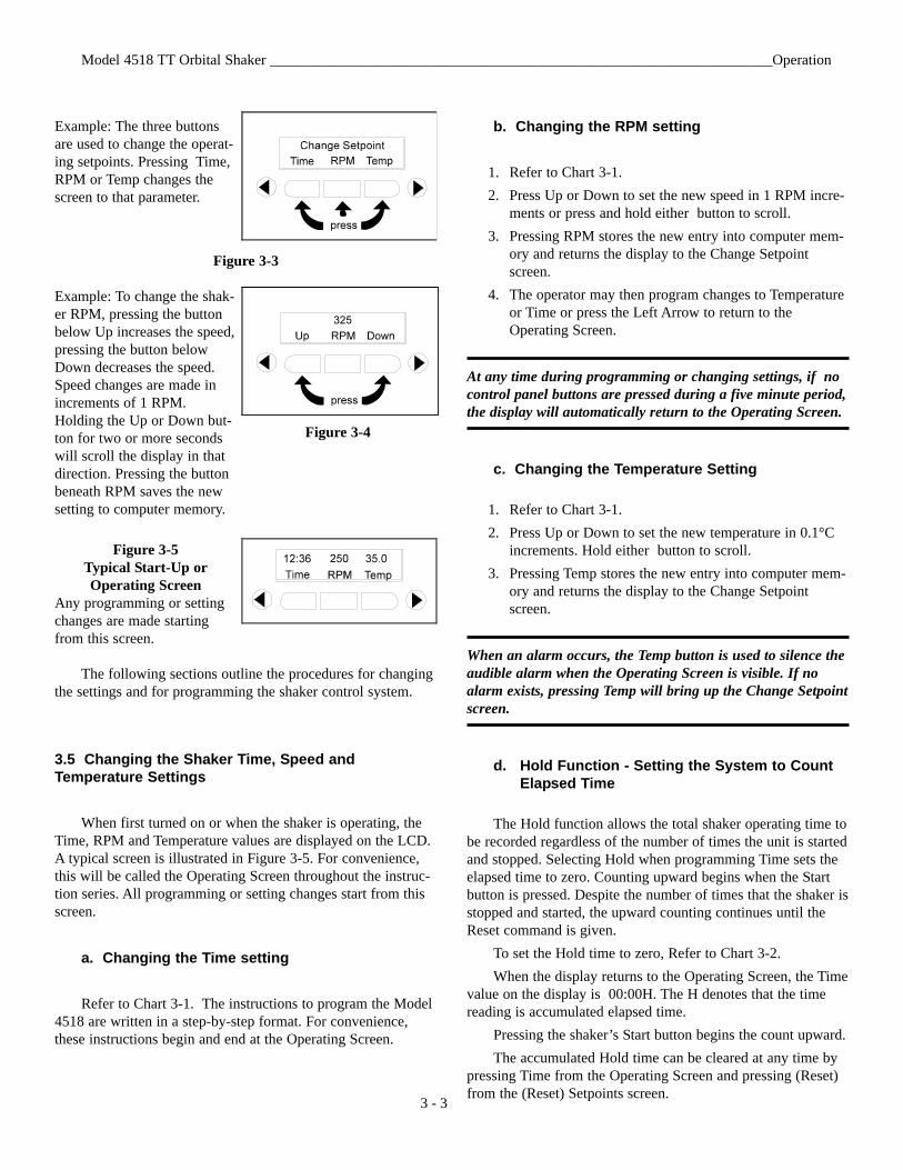
Example: The three buttonsare used to change the operat-ing setpoints. Pressing Time,RPM or Temp changes thescreen to that parameter.
Figure 3-3
Example: To change the shak-er RPM, pressing the buttonbelow Up increases the speed,pressing the button belowDown decreases the speed.Speed changes are made inincrements of 1 RPM.Holding the Up or Down but-ton for two or more secondswill scroll the display in thatdirection. Pressing the buttonbeneath RPM saves the newsetting to computer memory.
Figure 3-5Typical Start-Up orOperating Screen
Any programming or settingchanges are made startingfrom this screen.
The following sections outline the procedures for changingthe settings and for programming the shaker control system.
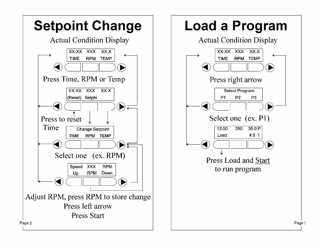
3.5 Changing the Shaker Time, Speed andTemperature Settings
When first turned on or when the shaker is operating, theTime, RPM and Temperature values are displayed on the LCD.A typical screen is illustrated in Figure 3-5. For convenience,this will be called the Operating Screen throughout the instruc-tion series. All programming or setting changes start from thisscreen.
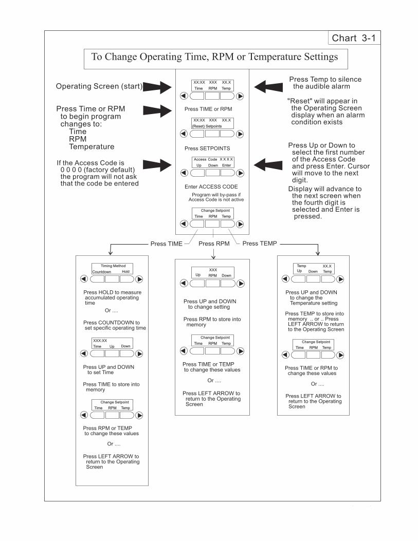
a. Changing the Time setting
Refer to Chart 3-1. The instructions to program the Model4518 are written in a step-by-step format. For convenience,these instructions begin and end at the Operating Screen.
b. Changing the RPM setting
1. Refer to Chart 3-1.2. Press Up or Down to set the new speed in 1 RPM incre-
ments or press and hold either button to scroll.3. Pressing RPM stores the new entry into computer mem-
ory and returns the display to the Change Setpointscreen.
4. The operator may then program changes to Temperatureor Time or press the Left Arrow to return to theOperating Screen.
At any time during programming or changing settings, if nocontrol panel buttons are pressed during a five minute period,the display will automatically return to the Operating Screen.
c. Changing the Temperature Setting
1. Refer to Chart 3-1.2. Press Up or Down to set the new temperature in 0.1°C
increments. Hold either button to scroll.3. Pressing Temp stores the new entry into computer mem-
ory and returns the display to the Change Setpointscreen.
When an alarm occurs, the Temp button is used to silence theaudible alarm when the Operating Screen is visible. If noalarm exists, pressing Temp will bring up the Change Setpointscreen.
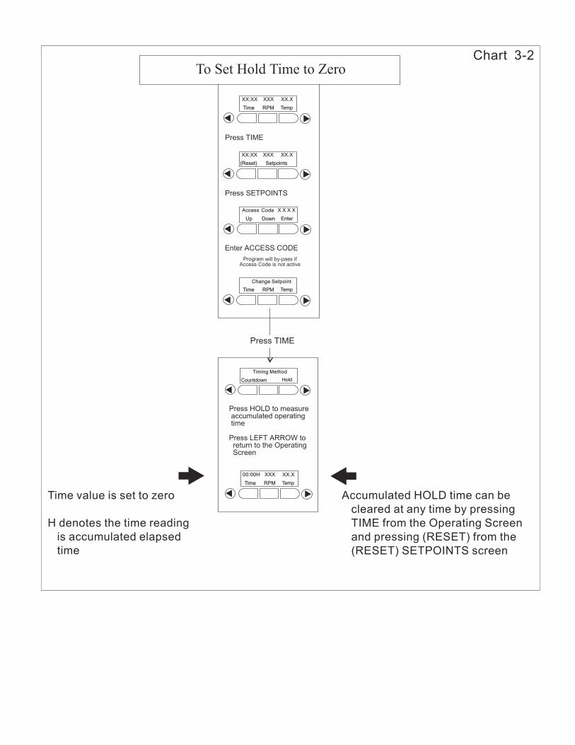
d. Hold Function - Setting the System to Count Elapsed Time
The Hold function allows the total shaker operating time tobe recorded regardless of the number of times the unit is startedand stopped. Selecting Hold when programming Time sets theelapsed time to zero. Counting upward begins when the Startbutton is pressed. Despite the number of times that the shaker isstopped and started, the upward counting continues until theReset command is given.
To set the Hold time to zero, Refer to Chart 3-2.When the display returns to the Operating Screen, the Time
value on the display is 00:00H. The H denotes that the timereading is accumulated elapsed time.
Pressing the shaker’s Start button begins the count upward.The accumulated Hold time can be cleared at any time by
pressing Time from the Operating Screen and pressing (Reset)from the (Reset) Setpoints screen.
Model 4518 TT Orbital Shaker ____________________________________________________________________Operation
Figure 3-4
3.6 Operating the Shaker using Pre-Set Programs
Three different pre-set programs may be stored in themicroprocessor’s memory. To operate the shaker using theseprograms, Refer to Chart 3-3.
The program selected will be displayed with the Time,RPM and Temp settings. A number 1, 2 or 3 in the lower rightcorner of the display shows which pre-set program is in use.
3.7 Making or Editing the Pre-Set Programs
To create a new set of operating parameters for Pre-SetProgram P1, P2 or P3, Refer to Chart 3-4.
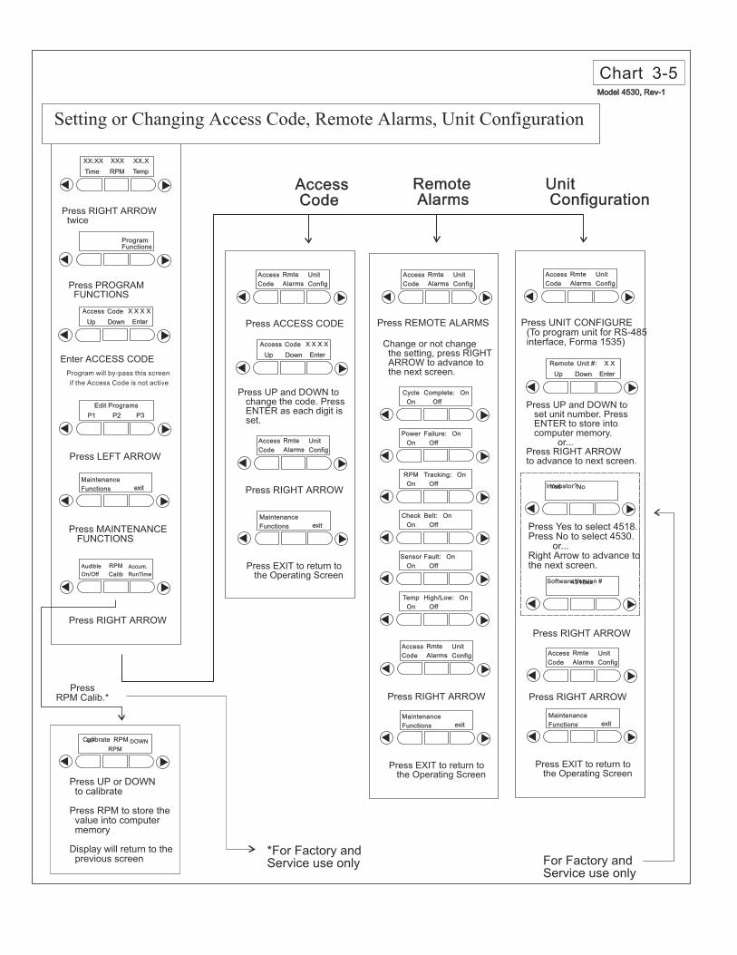
3.8 Changing/Setting the Access Code (Refer to Chart 3-5)
Record and file the new Access Code in a safe place. If thenew code is lost or forgotten, contact the Thermo FormaService Department.
3.9 Setting the Remote Alarms (Refer to Chart 3-5)
The Thermo Forma 4518 Orbital Shaker control systemmonitors and provides alarms for six operating parameters :
Cycle Complete Power FailureRPM Tracking Drive Belt Integrity Sensor Fault Temperature High/LowEach of these alarms may be independently turned on and
off to suit the operator or laboratory needs.
3.10 Audible and Visual Alarms
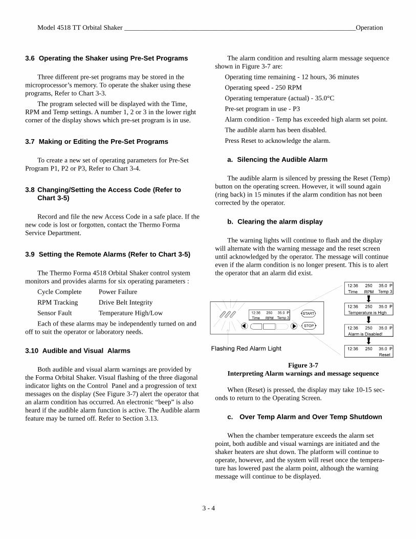
Both audible and visual alarm warnings are provided bythe Forma Orbital Shaker. Visual flashing of the three diagonalindicator lights on the Control Panel and a progression of textmessages on the display (See Figure 3-7) alert the operator thatan alarm condition has occurred. An electronic “beep” is alsoheard if the audible alarm function is active. The Audible alarmfeature may be turned off. Refer to Section 3.13.
The alarm condition and resulting alarm message sequenceshown in Figure 3-7 are:
Operating time remaining - 12 hours, 36 minutesOperating speed - 250 RPMOperating temperature (actual) - 35.0°CPre-set program in use - P3Alarm condition - Temp has exceeded high alarm set point.The audible alarm has been disabled.Press Reset to acknowledge the alarm.
a. Silencing the Audible Alarm
The audible alarm is silenced by pressing the Reset (Temp)button on the operating screen. However, it will sound again(ring back) in 15 minutes if the alarm condition has not beencorrected by the operator.
b. Clearing the alarm display
The warning lights will continue to flash and the displaywill alternate with the warning message and the reset screenuntil acknowledged by the operator. The message will continueeven if the alarm condition is no longer present. This is to alertthe operator that an alarm did exist.
Figure 3-7Interpreting Alarm warnings and message sequence
When (Reset) is pressed, the display may take 10-15 sec-onds to return to the Operating Screen.
c. Over Temp Alarm and Over Temp Shutdown
When the chamber temperature exceeds the alarm setpoint, both audible and visual warnings are initiated and theshaker heaters are shut down. The platform will continue tooperate, however, and the system will reset once the tempera-ture has lowered past the alarm point, although the warningmessage will continue to be displayed.
Model 4518 TT Orbital Shaker ____________________________________________________________________Operation
3 - 4
d. Raising and Lowering the Temperature Alarms Setpoints (Refer to Chart 3-6)
The temperatures at which the alarms activate are raised orlowered by following the instructions in Chart 3-6. The temper-atures are set or changed in 0.1°C increments. Pressing andholding the Up and Down buttons will cause the display toscroll in that direction.
3.11 Turning the Audible Alarm Feature On or Off (Refer to Chart 3-7)
At the operator’s discretion, the audible alarm warning fea-ture may be shut off. Refer to the instructions in Chart 3-7.
Turning off the audible alarm will not affect the flashingwarning light or the alarm messages presented on the displayscreen.
3.12 Reading the Accumulated Run Time (Refer toChart 3-8)
Accumulated running time may be read or viewed any timethe shaker is operating. The button-press sequence is listed inChart 3-8. The chart page also contains a date and time entryrecord box for convenience.
3.13 Temperature Calibration
The Model 4518 temperature monitoring system may becalibrated ±4°C from the factory setting. A thermometer ofknown accuracy must be used and the system allowed to stabi-lize before calibrating.
The programming sequence is shown below.From the Operating Screen:
1. Press the Right Arrow twice.2. Press Program Functions3. Press the Left Arrow twice.4. Press Temp Calib. 5. Using the Up and Down buttons, match the system tem-
perature with the temperature shown on the thermome-ter. Changes are made in 0.1°C increments.
6. When set, press Temp to return to the Over-Temp,Calibrate and Alarms screen.
7. Press the Right Arrow.8. Press Exit to return to the Operating Screen.
3.14 Reading the Over Temperature Probe
To compare the temperature being sensed by the over tem-perature probe with the actual temperature reading of the sys-tem, follow the procedures in the top half of Chart 3-6. Pressing“O-Temp” at the prompt will provide the Over Temperatureprobe information.
This function is mainly diagnostic and should be used forinformation only. Making any changes to the over temperaturesystem based on this reading should be made only by personstrained in servicing the Model 4518 Orbital Shaker.
3.15 Setting the Temperature Tracking Limit
From the Operating Screen:1. Press Right Arrow twice. 2. Press Program Function.3. Press Right Arrow twice.4. Press Alarms.5. Press Trackg to set the Tracking Limit using the Up and
Down buttons. When set, press Temp.6. Press Right Arrow twice.7. Press Exit to return to the Operating Screen.
Model 4518 TT Orbital Shaker ____________________________________________________________________Operation
3 - 5
Press SETPOINTS
Enter ACCESS CODE
Program will by-pass ifAccess Code is not active
Up
Time
Down
RPM
Enter
Temp
X X X XX X X XAccess
Change SetpointChange Setpoint
Code
Press TIME or RPM
Time RPM Temp
XX.XXX:XX XXX
(Reset) Setpoints(Reset) Setpoints
XX.XXX:XX XXX
Press TIME Press TEMPPress RPM
To Change Operating Time, RPM or Temperature Settings
Press HOLD to measureaccumulated operatingtime
Press COUNTDOWN toset specific operating time
Or ....
Or ....
Press TIME to store intomemory
Press RPM or TEMPto change these values
Press LEFT ARROW toreturn to the OperatingScreen
Press UP and DOWNto set Time
Countdown Hold
Timing MethodTiming Method
Time RPM Temp
Change SetpointChange Setpoint
Time Up Down
XXX:XX
Press RPM to store intomemory
Press UP and DOWNto change setting
RPM
XXX
Or ....
Press TIME or TEMPto change these values
Press LEFT ARROW toreturn to the OperatingScreen
Time RPM Temp
Change SetpointChange Setpoint
Up Down
Press TEMP to store intomemory .. or .. PressLEFT ARROW to returnto the Operating Screen
Press UP and DOWNto change theTemperature setting
Or ....
Press TIME or RPM tochange these values
Press LEFT ARROW toreturn to the OperatingScreen
Time RPM Temp
Change SetpointChange Setpoint
Temp
XX.XTemp
Up
Temp
Up Down
Chart 3-1
Operating Screen (start)
Press Time or RPMto begin programchanges to:
TimeRPMTemperature
Press Temp to silencethe audible alarm
"Reset" will appear inthe Operating Screendisplay when an alarmcondition exists
Press Up or Down toselect the first numberof the Access Codeand press Enter. Cursorwill move to the nextdigit.
Display will advance tothe next screen whenthe fourth digit isselected and Enter ispressed.
If the Access Code is0 0 0 0 (factory default)the program will not askthat the code be entered
(Ch t 01 CDR)
Press SETPOINTS
Enter ACCESS CODE
Program will by-pass ifAccess Code is not active
(Reset) Setpoints(Reset) Setpoints
Up
Time
Down
RPM
Enter
Temp
XX.X
X X X XX X X X
XX:XX
Access
Change SetpointChange Setpoint
XXX
Code
Press TIME
Time RPM Temp
XX.XXX:XX XXX
Time RPM Temp
XX.X00:00H XXX
Press TIME
To Set Hold Time to Zero
Press HOLD to measureaccumulated operatingtime
Press LEFT ARROW toreturn to the OperatingScreen
Countdown Hold
Timing MethodTiming Method
Time value is set to zero
H denotes the time reading
is accumulated elapsed
time
Accumulated HOLD time can be
cleared at any time by pressing
TIME from the Operating Screen
and pressing (RESET) from the
(RESET) SETPOINTS screen
Chart 3-2
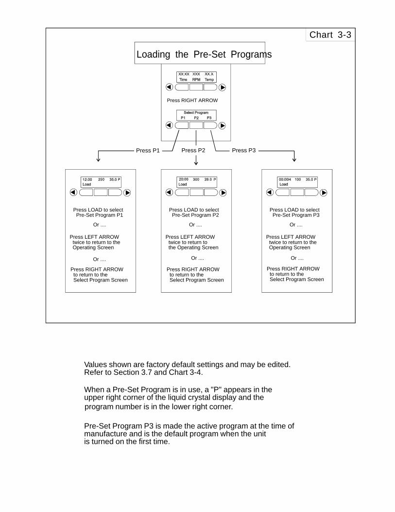
Press RIGHT ARROW
Press P1 Press P3Press P2
Loading the Pre-Set Programs
Press LOAD to selectPre-Set Program P2
Or ....
Press LEFT ARROWtwice to return tothe Operating Screen
Press LOAD to selectPre-Set Program P1
Or ....
Or .... Or ....
Press LEFT ARROWtwice to return to theOperating Screen
Press RIGHT ARROWto return to theSelect Program Screen
Press RIGHT ARROWto return to theSelect Program Screen
Press RIGHT ARROWto return to theSelect Program Screen
Press LOAD to selectPre-Set Program P3
Or ....
Or ....
Press LEFT ARROWtwice to return to theOperating Screen
Chart 3-3
Values shown are factory default settings and may be edited.Refer to Section 3.7 and Chart 3-4.
When a Pre-Set Program is in use, a "P" appears in theupper right corner of the liquid crystal display and the
Pre-Set Program P3 is made the active program at the time ofmanufacture and is the default program when the unitis turned on the first time.
program number is in the lower right corner.
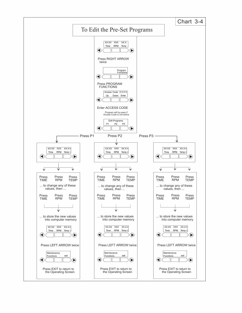
Press RIGHT ARROWtwice
Time RPM Temp
XX.XXX:XX XXX
Time RPM Temp
XX.XXX:XX XXX
Enter ACCESS CODE
Program will by-pass ifAccess Code is not active
Up Down Enter
X X X XX X X XAccess Code
Press PROGRAMFUNCTIONS
ProgramFunctionsProgramFunctions
P1 P2 P3
Edit ProgramsEdit Programs
Press P1 Press P3Press P2
To Edit the Pre-Set Programs
Chart 3-4
P
1
P
1
P
3
P
3Time RPM Temp
P
2
P
2
XX.XXX:XX XXX
Time RPM Temp
XX.XXX:XX XXX
Press EXIT to return tothe Operating Screen
exit
Maintenance
Functions
Maintenance
Functions
... to change any of thesevalues, then ...
... to store the new valuesinto computer memory
Press LEFT ARROW twice
Time RPM Temp
P
2
P
2
XX.XXX:XX XXX
PressRPM
PressTIME
PressTEMP
PressRPM
PressTIME
PressTEMP
Press EXIT to return tothe Operating Screen
exit
Maintenance
Functions
Maintenance
Functions
... to change any of thesevalues, then ...
... to store the new valuesinto computer memory
Press LEFT ARROW twice
Time RPM Temp
P
1
P
1
XX.XXX:XX XXX
PressRPM
PressTIME
PressTEMP
PressRPM
PressTIME
PressTEMP
Press EXIT to return tothe Operating Screen
exit
Maintenance
Functions
Maintenance
Functions
... to change any of thesevalues, then ...
... to store the new valuesinto computer memory
Press LEFT ARROW twice
Time RPM Temp
P
3
P
3
XX.XXX:XX XXX
PressRPM
PressTIME
PressTEMP
PressRPM
PressTIME
PressTEMP
Program will by-pass this screen
if the Access Code is not active
Press RIGHT ARROWtwice
Time RPM Temp
XX.XXX:XX XXX
Enter ACCESS CODE
Up Down Enter
X X X XX X X XAccess Code
Press PROGRAMFUNCTIONS
ProgramFunctionsProgramFunctions
P1 P2 P3
Edit ProgramsEdit Programs
Setting or Changing Access Code, Remote Alarms, Unit Configuration
Chart 3-5
exit
Maintenance
Functions
Maintenance
Functions
Press LEFT ARROW
Press MAINTENANCEFUNCTIONS
Press RIGHT ARROW
PressRPM Calib.*
Press UP or DOWNto calibrate
Press RPM to store thevalue into computermemory
Display will return to theprevious screen
Audible
On/Off
Audible
On/Off
UPCalibrate RPMCalibrate RPM
RPM
Calib
RPM
Calib
RPM
Accum.
RunTime
Accum.
RunTime
DOWN
For Factory andService use only
*For Factory andService use only
UnitConfigurationUnitConfiguration
RemoteAlarmsRemoteAlarms
AccessCode
AccessCode
Press UP and DOWN tochange the code. PressENTER as each digit isset.
Up Down Enter
X X X XX X X XAccess Code
Press EXIT to return tothe Operating Screen
exit
Maintenance
Functions
Maintenance
Functions
Access
Code
Access
Code
Rmte
Alarms
Rmte
Alarms
Unit
Config
Unit
Config
Access
Code
Access
Code
Rmte
Alarms
Rmte
Alarms
Unit
Config
Unit
Config
Access
Code
Access
Code
Rmte
Alarms
Rmte
Alarms
Unit
Config
Unit
Config
Press ACCESS CODE
Press RIGHT ARROW
Press RIGHT ARROW
Change or not changethe setting, press RIGHTARROW to advance tothe next screen.
Press EXIT to return tothe Operating Screen
exit
Maintenance
Functions
Maintenance
Functions
Access
Code
Access
Code
Rmte
Alarms
Rmte
Alarms
Unit
Config
Unit
Config
Cycle
On
Cycle
On
Power
On
Power
On
RPM
On
RPM
On
Check
On
Check
On
Sensor
On
Sensor
On
Temp
On
Temp
On
Complete: On
Off
Complete: On
Off
Failure: On
Off
Failure: On
Off
Tracking: On
Off
Tracking: On
Off
Belt: On
Off
Belt: On
Off
Fault: On
Off
Fault: On
Off
High/Low: On
Off
High/Low: On
Off
Press REMOTE ALARMS
Press UP and DOWN toset unit number. PressENTER to store intocomputer memory.
or...Press RIGHT ARROWto advance to next screen.
Up Down Enter
X XX XRemote Unit #:Unit #:
Press EXIT to return tothe Operating Screen
exit
Maintenance
Functions
Maintenance
Functions
Access
Code
Access
Code
Rmte
Alarms
Rmte
Alarms
Unit
Config
Unit
Config
Access
Code
Access
Code
Rmte
Alarms
Rmte
Alarms
Unit
Config
Unit
Config
Yes NoIncubator?Incubator?
Press UNIT CONFIGURE(To program unit for RS-485interface, Forma 1535)
Press RIGHT ARROW
Press RIGHT ARROW
Press Yes to select 4518.Press No to select 4530.
or...Right Arrow to advance tothe next screen.
4518xxSoftware Version #Software Version #
Model 4530, Rev-1Model 4530, Rev-1
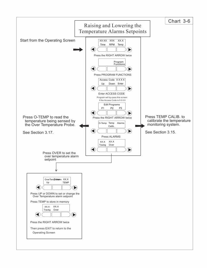
Chart 3-6
Press the RIGHT ARROW twice
Start from the Operating Screen
Press O-TEMP to read thetemperature being sensed bythe Over Temperature Probe.
See Section 3.17.
Press TEMP CALIB. tocalibrate the temperaturemonitoring system.
See Section 3.15.
Time RPM Temp
XX.XXX:XX XXX
Program will by-pass this screen
if the Access Code is 0 0 0 0
Enter ACCESS CODE
Up Down Enter
X X X XX X X XAccess Code
Press PROGRAM FUNCTIONS
ProgramFunctionsProgramFunctions
P1 P2 P3
Edit ProgramsEdit Programs
Press the RIGHT ARROW twice
Press ALARMS
O-Temp Temp
Calib.
Temp
Calib.
Alarms
XX.X
Trackg
XX.X
Trackg
XX.X
Over
XX.X
Over
Raising and Lowering theTemperature Alarms Setpoints
Press OVER to set theover temperature alarmsetpoint
Press UP or DOWN to set or change theOver Temperature alarm setpoint
Press TEMP to store in memory
Press the RIGHT ARROW twice
Then press EXIT to return to the
Operating Screen
OverTemp AlarmOverTemp Alarm
Up
Down XX.X
TEMP
XX.X
TEMP
XX.X
Trackg
XX.X
Trackg
XX.X
Over
XX.X
Over
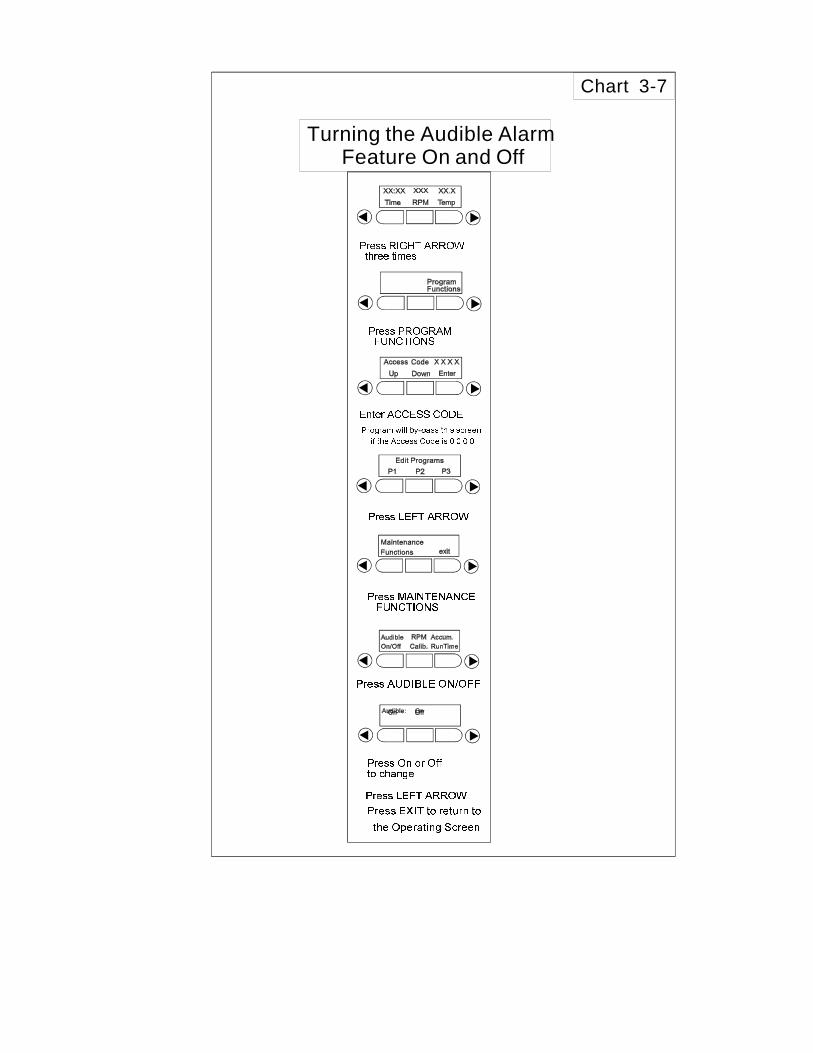
Chart 3-7
Turning the Audible AlarmFeature On and Off
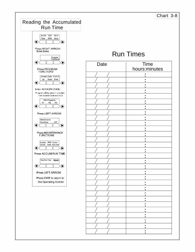
Chart 3-8
Reading the AccumulatedRun Time
Date
Run Times
Timehours:minutes
Section 4 - Maintenance
4.1 General Cleaning and Lubrication
The Thermo Forma Model 4518 Orbital Shaker uses abrushless DC motor and oversized, permanently lubricatedbearings which require no maintenance.
a. Shaker Platform and Cabinet
The anodized brushed aluminum platform and powder-coated steel cabinet surfaces can be cleaned with common labo-ratory materials. However, liquids should not be allowed toenter the shaker cabinet from under the platform. All spillsshould be cleaned up immediately. If necessary, remove theplatform. Follow the procedures in Section 2.2.b when re-installing the platform.
b. Control Panel
The microprocessor control panel uses sealed push buttonsand liquid crystal display and may be cleaned with laboratorydetergents and dried with a soft cloth.
Section 5 - Service
The procedures outlined in this section should beperformed by persons experienced in servicingand maintaining laboratory equipment. Lockoutand tagout electrical power connections wheneverremoving cabinet panels or working on electricalor motor control components.
With the exception of replacing the drive v-belt and the sixelectrical fuses, the Model 4518 Orbital Shaker contains nouser-serviceable components. The following table lists displaymessages which may help diagnose abnormal conditions.
5.1 Alarms and Alarm Conditions
If the microprocessor control system senses a fault, mal-function or abnormal operating condition, alarm messages willappear on the liquid crystal display. These messages will behelpful should service or repair assistance be necessary.
Alarm Message Fault ConditionOvertemp Shutdown System shutdown due to overtemp
conditionMain Temp Sensor Temperature sensor has failedOver Temp Sensor Temperature sensor has failedTemperature is High Temperature tracking has sensed
higher temperature than settingTemperature is Low Temperature tracking has sensed
lower temperature than settingPower Failure Power has failed during shaker
operationCycle CompleteCheck Belt Motor V-belt has brokenResetAudible is Disabled!
Model 4518 TT Orbital Shaker ___________________________________________________________Maintenance / Service
5 - 1
5.2. General Fault Conditions
5.3 Adjusting the Drive V-Belt Tension
Tools needed: Phillips screwdriver3/8” drive socket wrench with 7/16” socket
1. Remove all connectors and the line cord from the backof the shaker.
2. Lift the front of the shaker and rest it on the back of thecabinet. Remember, the weight of the shaker is 153pounds.
The shaker is not stable when set on its back. Asecond person may be necessary to support theshaker when in this position.
Symptom What to Check & Where to Look
Display is dark, shakerwill not operate
Power at the wall outletFuses on the back of the unit areblown Power switch not turned on
Display is lit, motorwill not operate
Voltage selector switch at wrongpositionDrive motor fuses on back of cabi-net are blownAcrylic lid is not closedNo time value entered into the sys-tem (see Section 3.5)Time countdown has been reached(see Section 3.5)
Display is on, motoroperates, display shows7.5°C or over temp state
Faulty temperature sensorFaulty over temperature sensor
Display is on, motoroperates, fan(s) do notrun
Blower motor fuses are blownConnections or wires to fan relayboard interruptedLid switch faulty or lid ajar
Display is on, heat is onbut fans and motor donot operate
Voltage selector switch Over temperature safety resettripped
Display on, unit will notoperate (Time readszero)
Countdown time reached, resetTIME Section 3.5a
Forgot the Access Code Call Thermo Forma ServiceDepartment
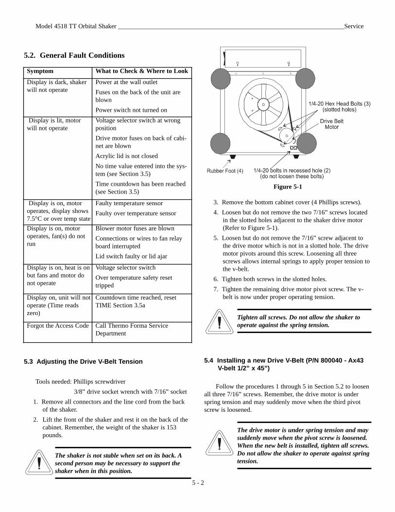
Figure 5-1
3. Remove the bottom cabinet cover (4 Phillips screws).4. Loosen but do not remove the two 7/16” screws located
in the slotted holes adjacent to the shaker drive motor(Refer to Figure 5-1).
5. Loosen but do not remove the 7/16” screw adjacent tothe drive motor which is not in a slotted hole. The drivemotor pivots around this screw. Loosening all threescrews allows internal springs to apply proper tension tothe v-belt.
6. Tighten both screws in the slotted holes.7. Tighten the remaining drive motor pivot screw. The v-
belt is now under proper operating tension.
Tighten all screws. Do not allow the shaker tooperate against the spring tension.
5.4 Installing a new Drive V-Belt (P/N 800040 - Ax43 V-belt 1/2” x 45”)
Follow the procedures 1 through 5 in Section 5.2 to loosenall three 7/16” screws. Remember, the drive motor is underspring tension and may suddenly move when the third pivotscrew is loosened.
The drive motor is under spring tension and maysuddenly move when the pivot screw is loosened.When the new belt is installed, tighten all screws.Do not allow the shaker to operate against springtension.
Model 4518 TT Orbital Shaker ______________________________________________________________________Service
5 - 2
1. Place the new v-belt around the bottom of both themotor and the large drive wheel.
2. Force the drive motor inward toward the drive wheel androtate the drive wheel counterclockwise, forcing the v-belt into the wheel grove. It may be necessary to use alever (large screwdriver or pry bar) to move the drivemotor inward against the spring tension. The large rub-ber foot can be used to pry against. Once the belt isproperly seated in the motor and drive wheels, the inter-nal springs apply proper tension.
3. Tighten the two screws in the slotted holes then tightenthe drive motor pivot screw.
4. Replace the bottom cover and return the shaker to serv-ice.
5.5 Troubleshooting and replacing the Circuit Boards
a. Removing the Control Panel
The Control Panel is attached to the cabinet by press-infasteners. Two indents are located along the bottom edge of thepanel which accommodate a flat screwdriver blade. (See Figure5-2) Carefully pry the panel outward to release the fasteners.The display circuit board is attached to the pack of the controlpanel, P/N 190438.
Figure 5-2Removing the Control Panel
The Control Panel is connected to the MicroprocessorBoard by a ribbon cable. Two locking clips on the ControlPanel connector must be release before the cable is removed.
When replacing the Control Panel, do not crimp the blueribbon cable on the left side of the circuit board. The cablemust be completely inside the sheet metal front panel before theControl Panel is pressed into place.
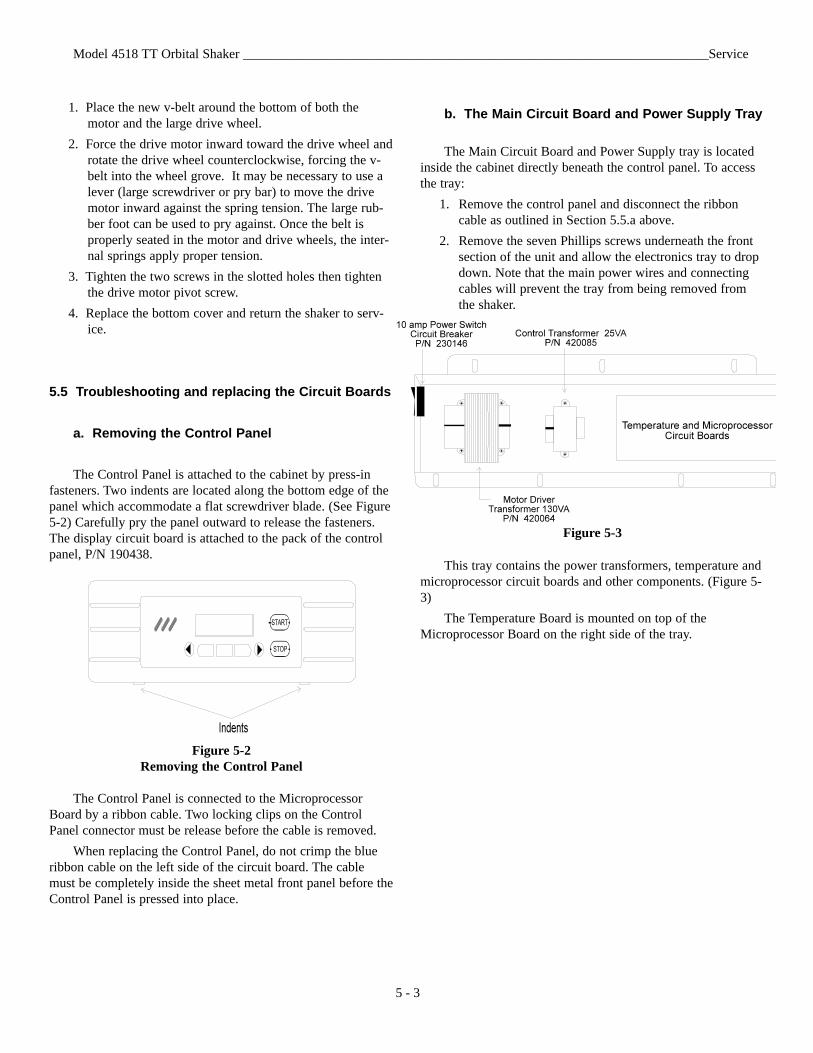
b. The Main Circuit Board and Power Supply Tray
The Main Circuit Board and Power Supply tray is locatedinside the cabinet directly beneath the control panel. To accessthe tray:
1. Remove the control panel and disconnect the ribboncable as outlined in Section 5.5.a above.
2. Remove the seven Phillips screws underneath the frontsection of the unit and allow the electronics tray to dropdown. Note that the main power wires and connectingcables will prevent the tray from being removed fromthe shaker.
Figure 5-3
This tray contains the power transformers, temperature andmicroprocessor circuit boards and other components. (Figure 5-3)
The Temperature Board is mounted on top of theMicroprocessor Board on the right side of the tray.
Model 4518 TT Orbital Shaker ______________________________________________________________________Service
5 - 3
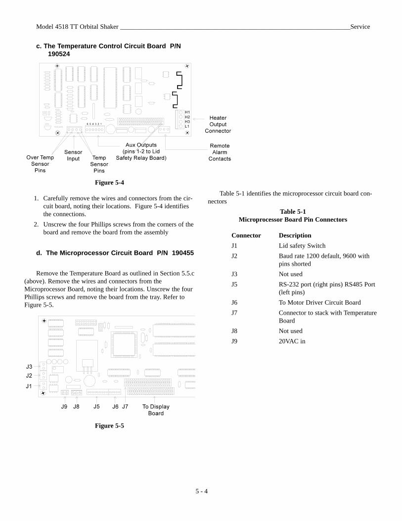
c. The Temperature Control Circuit Board P/N 190524
Figure 5-4
1. Carefully remove the wires and connectors from the cir-cuit board, noting their locations. Figure 5-4 identifiesthe connections.
2. Unscrew the four Phillips screws from the corners of theboard and remove the board from the assembly
d. The Microprocessor Circuit Board P/N 190455
Remove the Temperature Board as outlined in Section 5.5.c(above). Remove the wires and connectors from theMicroprocessor Board, noting their locations. Unscrew the fourPhillips screws and remove the board from the tray. Refer toFigure 5-5.
Figure 5-5
Table 5-1 identifies the microprocessor circuit board con-nectors
Table 5-1Microprocessor Board Pin Connectors
Connector DescriptionJ1 Lid safety SwitchJ2 Baud rate 1200 default, 9600 with
pins shortedJ3 Not usedJ5 RS-232 port (right pins) RS485 Port
(left pins)J6 To Motor Driver Circuit BoardJ7 Connector to stack with Temperature
BoardJ8 Not usedJ9 20VAC in
Model 4518 TT Orbital Shaker ______________________________________________________________________Service
5 - 4
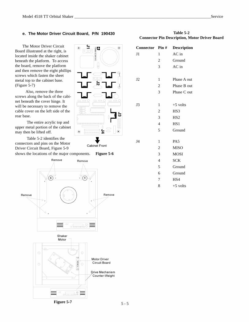
e. The Motor Driver Circuit Board, P/N 190430
The Motor Driver CircuitBoard illustrated at the right, islocated inside the shaker cabinetbeneath the platform. To accessthe board, remove the platformand then remove the eight phillipsscrews which fasten the sheetmetal top to the cabinet base.(Figure 5-7)
Also, remove the threescrews along the back of the cabi-net beneath the cover hinge. Itwill be necessary to remove thecable cover on the left side of therear base.
The entire acrylic top andupper metal portion of the cabinetmay then be lifted off.
Table 5-2 identifies theconnectors and pins on the MotorDriver Circuit Board, Figure 5-9shows the locations of the major components. Figure 5-6
Figure 5-7
Table 5-2Connector Pin Description, Motor Driver Board
Connector Pin # DescriptionJ1 1 AC in
2 Ground3 AC in
J2 1 Phase A out2 Phase B out3 Phase C out
J3 1 +5 volts2 HS33 HS24 HS15 Ground
J4 1 PA52 MISO3 MOSI4 SCK5 Ground6 Ground7 HS48 +5 volts
Model 4518 TT Orbital Shaker ___________________________________________________________________Service
5 - 5
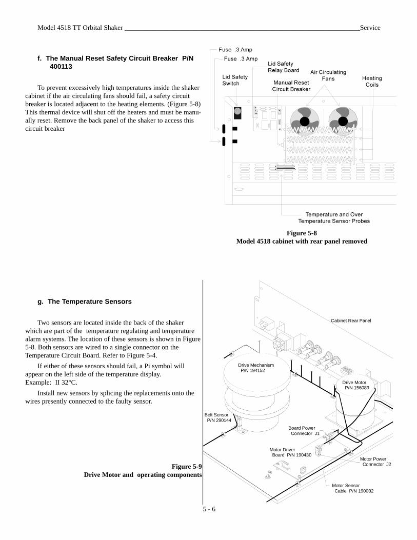
f. The Manual Reset Safety Circuit Breaker P/N 400113
To prevent excessively high temperatures inside the shakercabinet if the air circulating fans should fail, a safety circuitbreaker is located adjacent to the heating elements. (Figure 5-8)This thermal device will shut off the heaters and must be manu-ally reset. Remove the back panel of the shaker to access thiscircuit breaker
Model 4518 TT Orbital Shaker _____________________________________________________________________Service
G R N
RED
R ED
Board Power Connector J1
Drive Mechanism P/N 194152
Belt Sensor P/N 290144
Drive Motor P/N 156089
Cabinet Rear Panel
Motor Power Connector J2
Motor Sensor Cable P/N 190002
Motor Driver Board P/N 190430
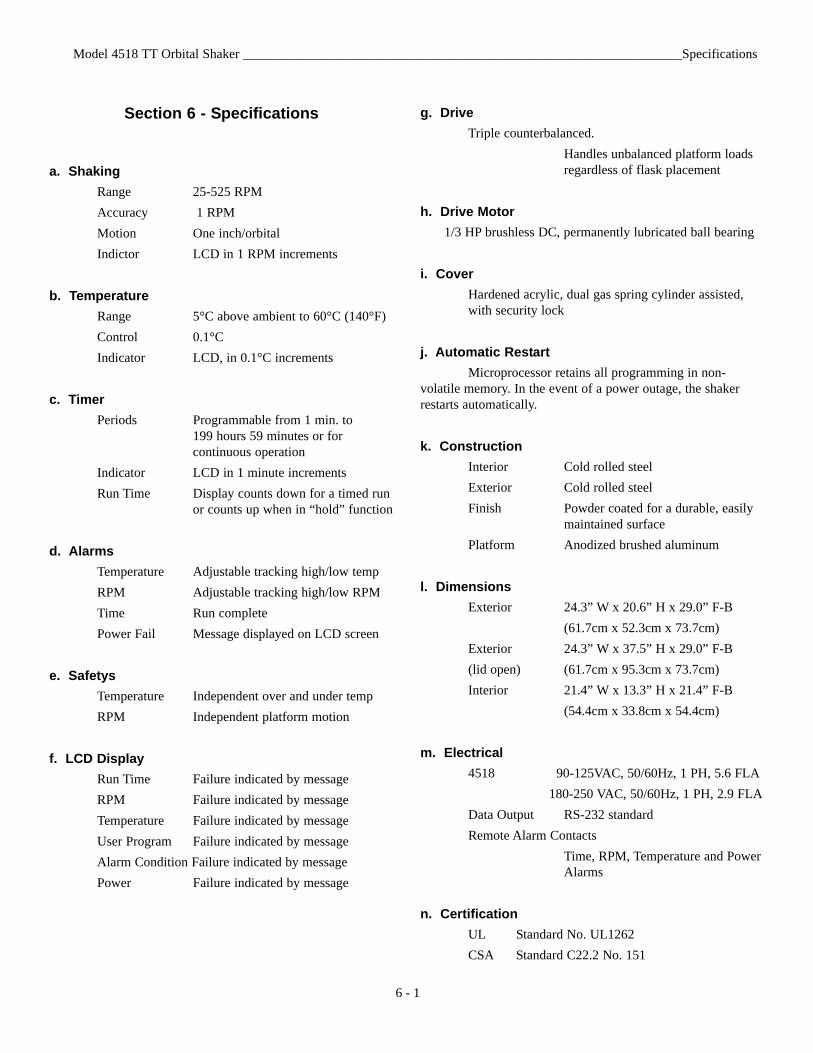
Figure 5-9Drive Motor and operating components
5 - 6
Figure 5-8Model 4518 cabinet with rear panel removed
g. The Temperature Sensors
Two sensors are located inside the back of the shakerwhich are part of the temperature regulating and temperaturealarm systems. The location of these sensors is shown in Figure5-8. Both sensors are wired to a single connector on theTemperature Circuit Board. Refer to Figure 5-4.
If either of these sensors should fail, a Pi symbol willappear on the left side of the temperature display. Example: II 32°C.
Install new sensors by splicing the replacements onto thewires presently connected to the faulty sensor.
Section 6 - Specifications
a. ShakingRange 25-525 RPMAccuracy 1 RPMMotion One inch/orbitalIndictor LCD in 1 RPM increments
b. TemperatureRange 5°C above ambient to 60°C (140°F)Control 0.1°CIndicator LCD, in 0.1°C increments
c. TimerPeriods Programmable from 1 min. to
199 hours 59 minutes or for continuous operation
Indicator LCD in 1 minute incrementsRun Time Display counts down for a timed run
or counts up when in “hold” function
d. AlarmsTemperature Adjustable tracking high/low tempRPM Adjustable tracking high/low RPMTime Run completePower Fail Message displayed on LCD screen
e. SafetysTemperature Independent over and under tempRPM Independent platform motion
f. LCD DisplayRun Time Failure indicated by messageRPM Failure indicated by messageTemperature Failure indicated by messageUser Program Failure indicated by messageAlarm Condition Failure indicated by messagePower Failure indicated by message
Model 4518 TT Orbital Shaker __________________________________________________________________Specifications
6 - 1
g. DriveTriple counterbalanced.
Handles unbalanced platform loads regardless of flask placement
h. Drive Motor1/3 HP brushless DC, permanently lubricated ball bearing
i. CoverHardened acrylic, dual gas spring cylinder assisted, with security lock
j. Automatic RestartMicroprocessor retains all programming in non-
volatile memory. In the event of a power outage, the shakerrestarts automatically.
k. ConstructionInterior Cold rolled steelExterior Cold rolled steelFinish Powder coated for a durable, easily
maintained surfacePlatform Anodized brushed aluminum
l. DimensionsExterior 24.3” W x 20.6” H x 29.0” F-B
(61.7cm x 52.3cm x 73.7cm)Exterior 24.3” W x 37.5” H x 29.0” F-B(lid open) (61.7cm x 95.3cm x 73.7cm)Interior 21.4” W x 13.3” H x 21.4” F-B
(54.4cm x 33.8cm x 54.4cm)
m. Electrical4518 90-125VAC, 50/60Hz, 1 PH, 5.6 FLA
180-250 VAC, 50/60Hz, 1 PH, 2.9 FLAData Output RS-232 standardRemote Alarm Contacts
Time, RPM, Temperature and Power Alarms
n. CertificationUL Standard No. UL1262CSA Standard C22.2 No. 151
o. CapacityFlasks From (49) 25ml up to (5) 2L
p. WeightsNet 153 lbs. (69.5kg)Shipping 191 lbs. (86.7kg)
q. Optional PlatformsSize 18” x 18” (45.7cm x 45.7cm)Clips 25ml, 50ml, 125ml
Model 4518 TT Orbital Shaker __________________________________________________________________Parts List
7 - 1
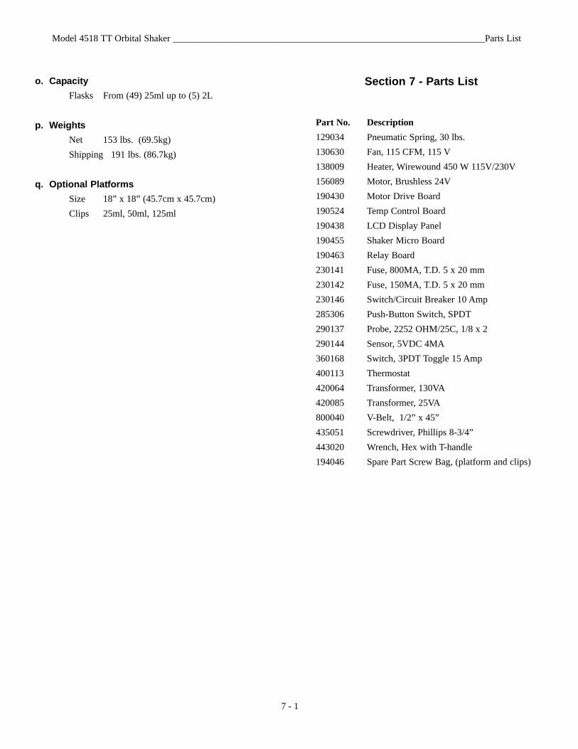
Section 7 - Parts List
Part No. Description129034 Pneumatic Spring, 30 lbs.130630 Fan, 115 CFM, 115 V138009 Heater, Wirewound 450 W 115V/230V156089 Motor, Brushless 24V190430 Motor Drive Board190524 Temp Control Board190438 LCD Display Panel190455 Shaker Micro Board190463 Relay Board230141 Fuse, 800MA, T.D. 5 x 20 mm230142 Fuse, 150MA, T.D. 5 x 20 mm230146 Switch/Circuit Breaker 10 Amp285306 Push-Button Switch, SPDT290137 Probe, 2252 OHM/25C, 1/8 x 2290144 Sensor, 5VDC 4MA360168 Switch, 3PDT Toggle 15 Amp400113 Thermostat420064 Transformer, 130VA420085 Transformer, 25VA800040 V-Belt, 1/2” x 45”435051 Screwdriver, Phillips 8-3/4” 443020 Wrench, Hex with T-handle194046 Spare Part Screw Bag, (platform and clips)
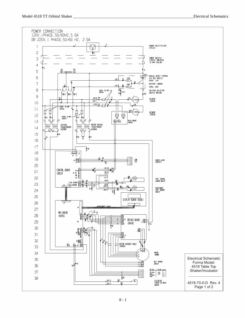
Model 4518 TT Orbital Shaker ____________________________________________________________Electrical Schematics
8 - 1
Electrical Schematic
Forma Model:
4518 Table Top
Shaker/Incubator
4518-70-0-D Rev. 4
Page 1 of 2
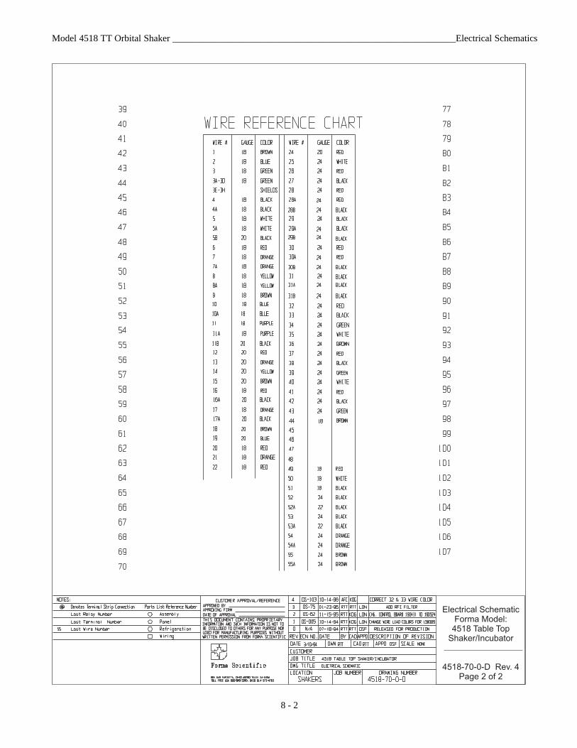
Model 4518 TT Orbital Shaker ____________________________________________________________Electrical Schematics
8 - 2
Electrical Schematic
Forma Model:
4518 Table Top
Shaker/Incubator
4518-70-0-D Rev. 4
Page 2 of 2

Thermo FormaMillcreek Road, P.O. Box 649
Marietta, Ohio 45750U.S.A.
Telephone (740) 373-4763Telefax (740) 373-4189