Embed Size (px)
Citation preview
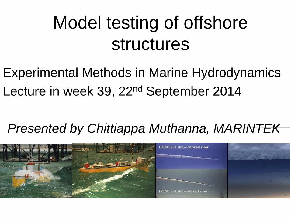
Model testing of offshore structures
Experimental Methods in Marine Hydrodynamics Lecture in week 39, 22nd September 2014 Presented by Chittiappa Muthanna, MARINTEK
Outline • Part I: Offshore Structures
– Typical test objectives, requirements and set-ups – Documentation tests – Modeling of risers and anchor lines – Importance of slow drift motions – Challenges in deep water exploration – and model testing!
• Minimization of models • Truncation of risers and mooring lines • Hybrid model testing
– Marine operations – challenges and typical model tests
• Part II: Vortex Induced Vibrations – Introduction – 2D tests of rigid cylinders – 3D tests of long elastic cylinders
Offshore structures • ”All other applications except ships in transit”
Examples: – Floating platforms and ships applied for production and/or
storage of oil and gas – Fixed structures – Risers – Mooring systems – Floating and submerged bridges – Fish farming structures – Offshore windmills (fixed & floating)
• Commonality: Hydrodynamic problems are important. In most cases are also surface waves involved
Typical Test Objectives 1. Feasibility studies
• Early stage of new concepts / new applications / new environments
2. Concept Verification studies • Apply design loads to a completely modeled structure to verify that it
satisfies requirements • Typically an oil installation (drilling rig, production or storage unit)
3. Operational limits studies
• Typically the limiting sea state of a demanding marine operation
4. Parts testing studies • Experiments with parts of a complex system • Determination of coefficients (drag , added mass, damping, RAOs …)
for input to numerical simulations
5. Validation and/or verification of software • For actual type of structure and loading condition
Typical Test Requirements For concept verifications and operational limits studies
• Zero (or very low) speed • High-accuracy modeling of complete environment
– Multi-directional and short-crested waves – Time-varying wind (correctly modeled gusts) – Depth- (and time-) varying current
• Correctly (Froude) scaled water depth – is often important
• Correctly (Froude) scaled risers and mooring lines • Low speed and requirement for high accuracy waves
implies a short but wide “tank” (=basin)
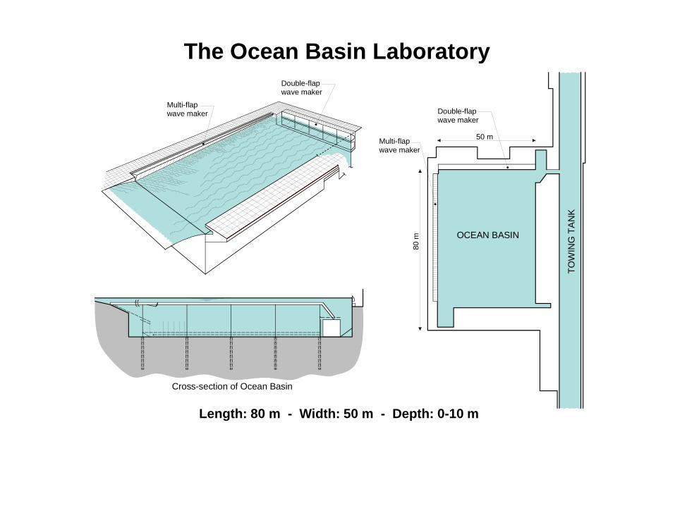
The Ocean Basin Laboratory
Length: 80 m - Width: 50 m - Depth: 0-10 m
TOW
ING
TA
NK
OCEAN BASIN
50 mMulti-flapwave maker
80 m
Cross-section of Ocean Basin
Double-flapwave maker
Multi-flapwave maker Double-flap
wave maker
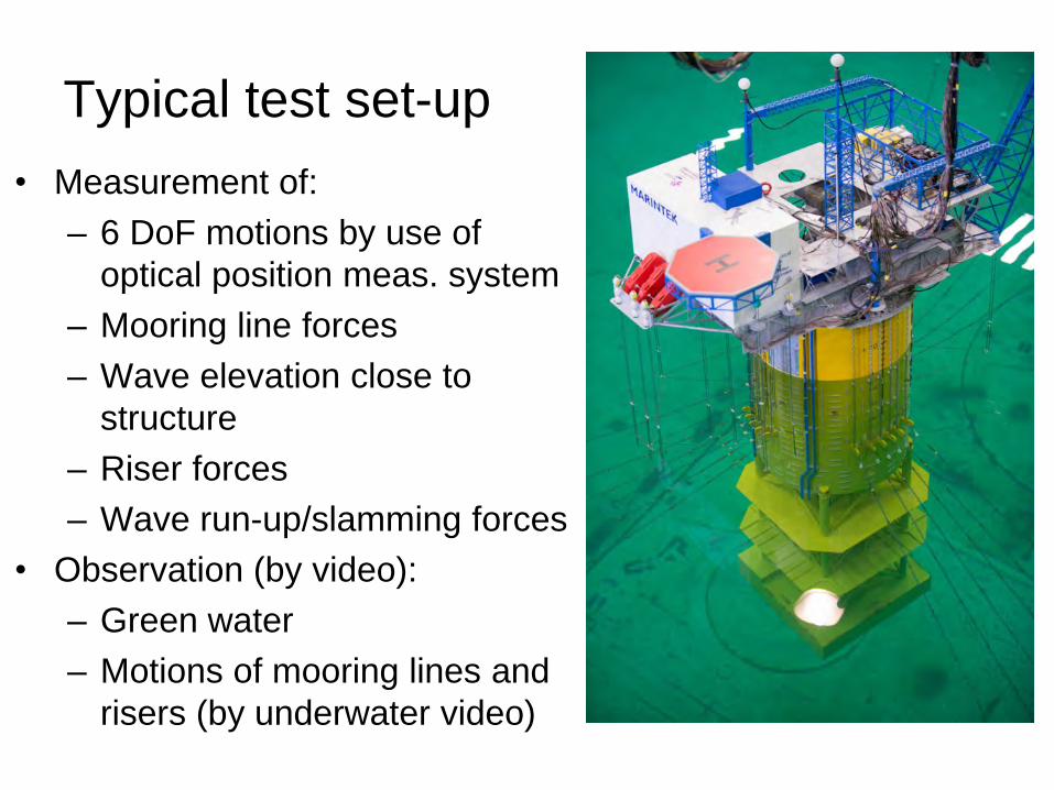
Typical test set-up • Measurement of:
– 6 DoF motions by use of optical position meas. system
– Mooring line forces – Wave elevation close to
structure – Riser forces – Wave run-up/slamming forces
• Observation (by video): – Green water – Motions of mooring lines and
risers (by underwater video)
Scaling considerations
• Floater (ship or platform) built to geometrical scale – No particular scaling problems of motions and global loads
• Risers: – Correct drag coefficient of sections
• Scale effects – modify diameter to obtain correct forces – Froude-scaled bending stiffness – Correctly scaled weight in water
• Mooring lines – Axial stiffness might need to be modeled, but bending
stiffness might be neglected ⇒Solution:
Non-homogeneous models of risers and mooring lines
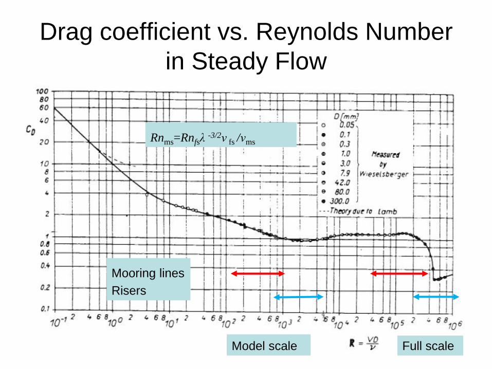
Drag coefficient vs. Reynolds Number in Steady Flow
Mooring lines Risers
Model scale Model scale Full scale
Rnms=Rnfsλ -3/2ν fs /νms
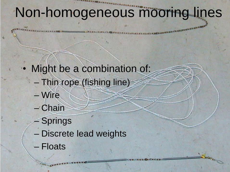
Non-homogeneous mooring lines
• Might be a combination of: – Thin rope (fishing line) – Wire – Chain – Springs – Discrete lead weights – Floats
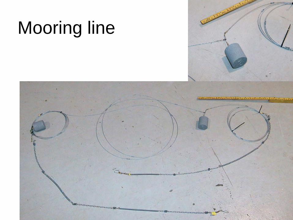
Mooring line
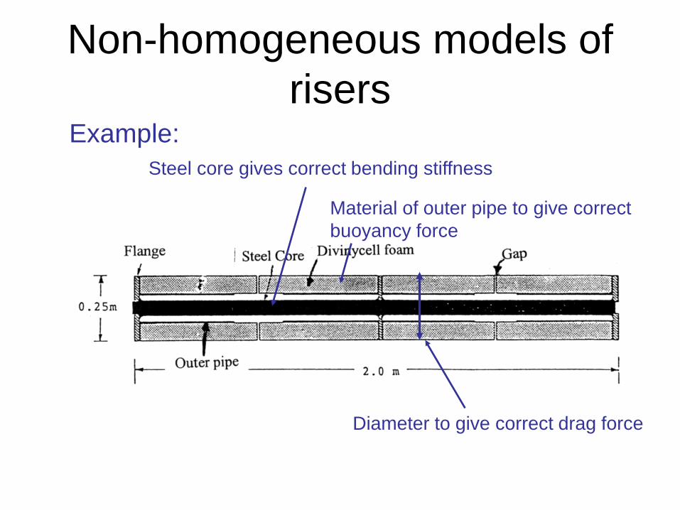
Non-homogeneous models of risers
Example: Steel core gives correct bending stiffness
Diameter to give correct drag force
Material of outer pipe to give correct buoyancy force
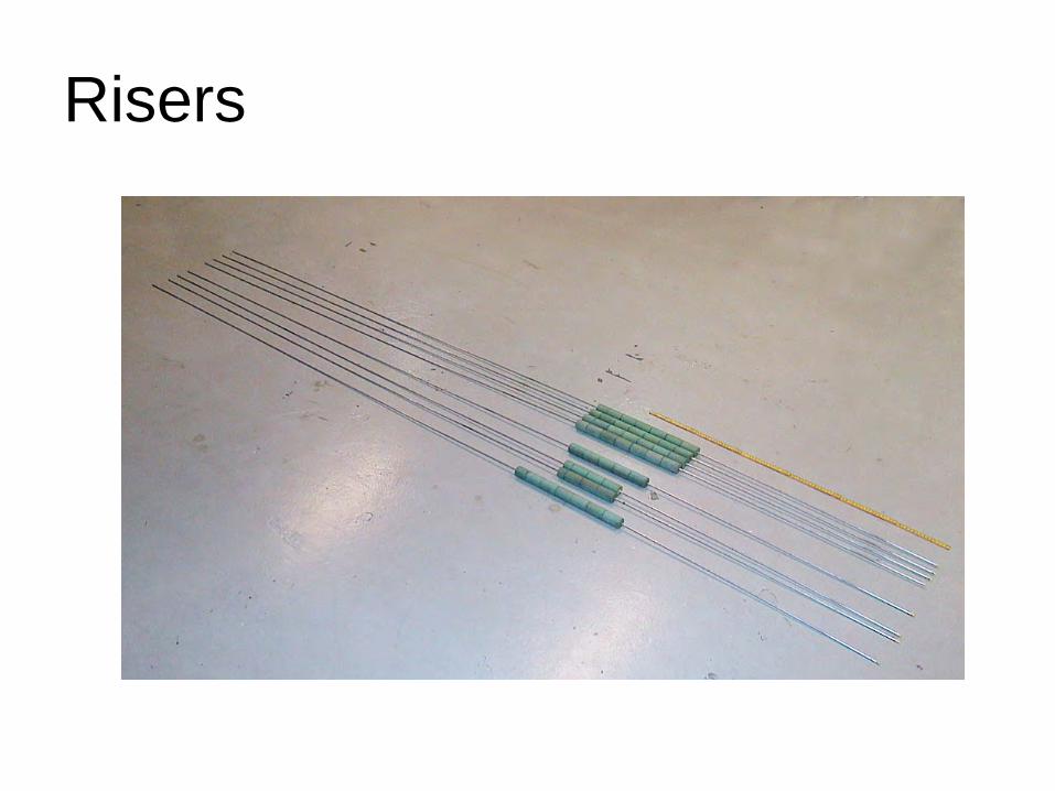
Risers
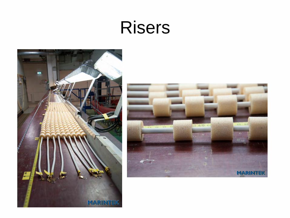
Risers
Documentation tests • The tests are performed in order to document
that the models and test set-ups are functioning as intended
• They are important • Purposeless to continue if resonance periods are wrong • Avoid unwanted/unintended resonance period of the test
set-up was within the response period range
• Type of documentation tests • Decay tests • Pluck tests • Static pull-out tests • Test wave
Decay tests
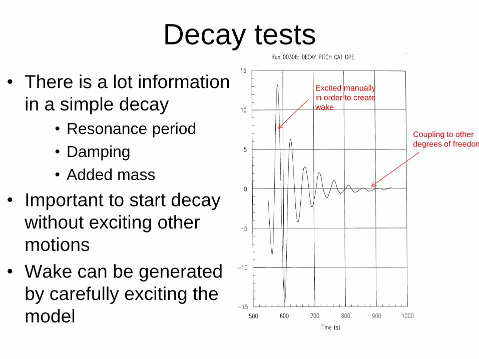
Coupling to other degrees of freedom
Excited manually in order to create wake
• There is a lot information in a simple decay
• Resonance period • Damping • Added mass
• Important to start decay without exciting other motions
• Wake can be generated by carefully exciting the model
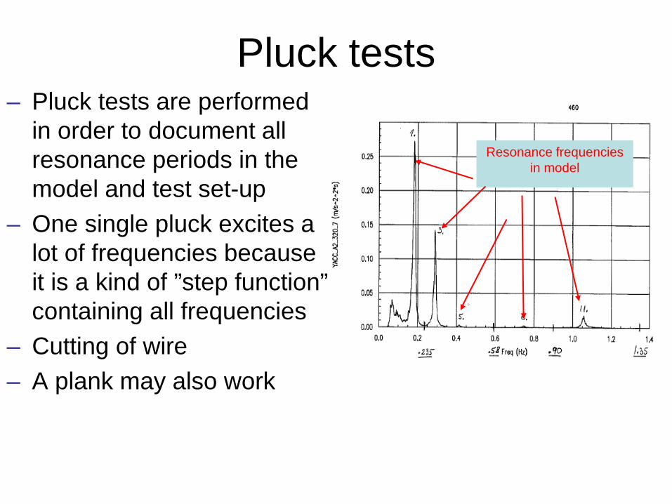
Resonance frequencies in model
Pluck tests – Pluck tests are performed
in order to document all resonance periods in the model and test set-up
– One single pluck excites a lot of frequencies because it is a kind of ”step function” containing all frequencies
– Cutting of wire – A plank may also work
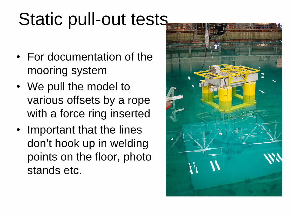
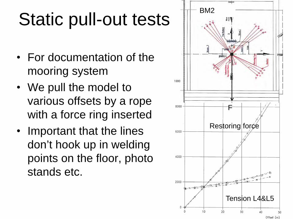
Static pull-out tests
• For documentation of the mooring system
• We pull the model to various offsets by a rope with a force ring inserted
• Important that the lines don’t hook up in welding points on the floor, photo stands etc.
Static pull-out tests
• For documentation of the mooring system
• We pull the model to various offsets by a rope with a force ring inserted
• Important that the lines don’t hook up in welding points on the floor, photo stands etc.
BM2
F
Restoring force
Tension L4&L5
Test wave
• The test wave is run for verification that – the wave makers are working properly – the instrumentation is stable – the test set-up doesn’t change characteristics
during the test period (re-rigging, rotation of set up for new heading etc.)
• Using a standard test wave, but a wave condition specially designed for the project can also be used
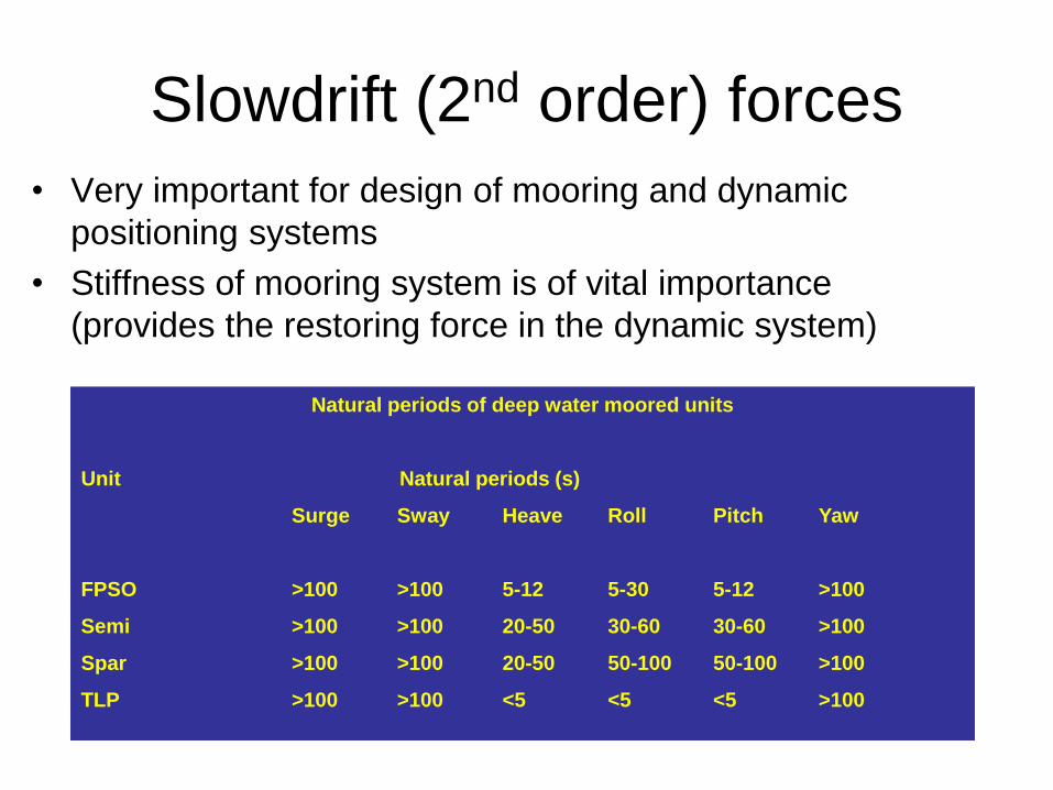
Slowdrift (2nd order) forces • Very important for design of mooring and dynamic
positioning systems • Stiffness of mooring system is of vital importance
(provides the restoring force in the dynamic system)
Natural periods of deep water moored units
Unit Natural periods (s)
Surge Sway Heave Roll Pitch Yaw
FPSO >100 >100 5-12 5-30 5-12 >100
Semi >100 >100 20-50 30-60 30-60 >100
Spar >100 >100 20-50 50-100 50-100 >100
TLP >100 >100 <5 <5 <5 >100
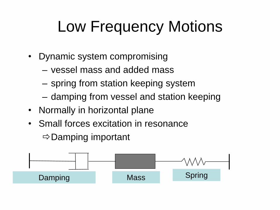
Low Frequency Motions
• Dynamic system compromising – vessel mass and added mass – spring from station keeping system – damping from vessel and station keeping
• Normally in horizontal plane • Small forces excitation in resonance Damping important
Damping Spring Mass
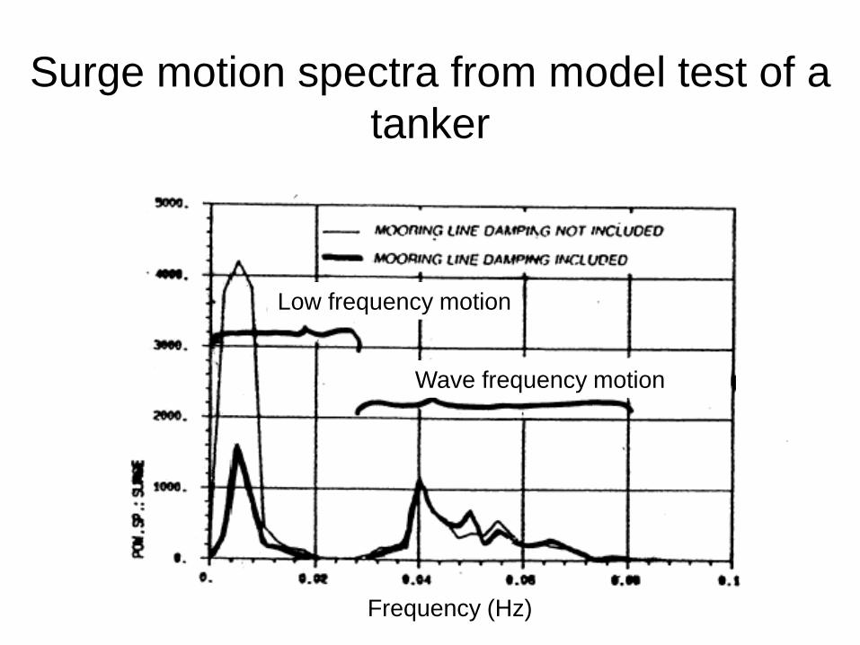
Surge motion spectra from model test of a tanker
Frequency (Hz)
Low frequency motion
Wave frequency motion
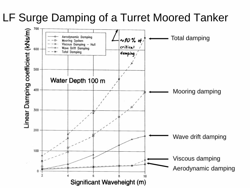
LF Surge Damping of a Turret Moored Tanker
Aerodynamic damping
Wave drift damping
Viscous damping
Mooring damping
Total damping
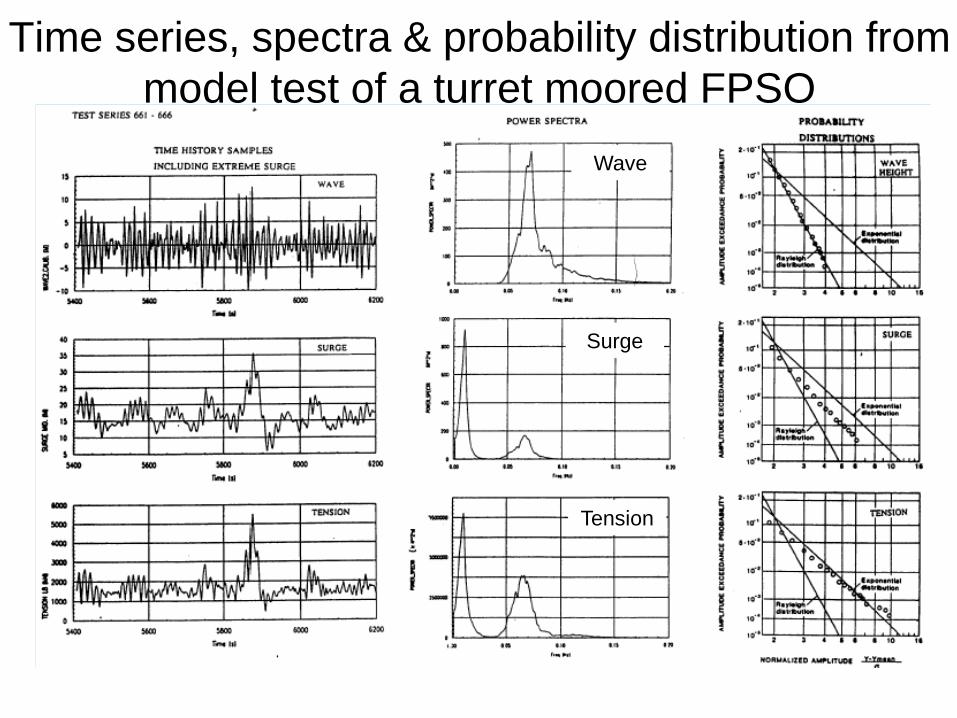
Time series, spectra & probability distribution from model test of a turret moored FPSO
Wave
Tension
Surge
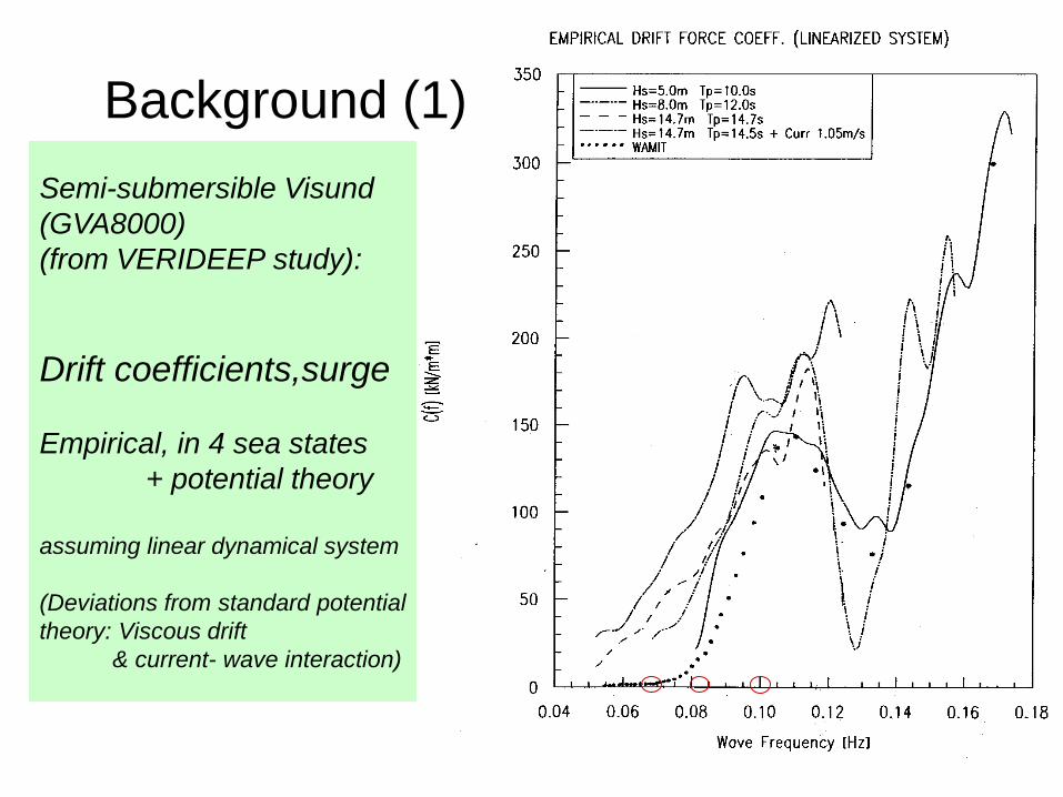
Semi-submersible Visund (GVA8000) (from VERIDEEP study): Drift coefficients,surge Empirical, in 4 sea states + potential theory assuming linear dynamical system (Deviations from standard potential theory: Viscous drift & current- wave interaction)
Background (1)
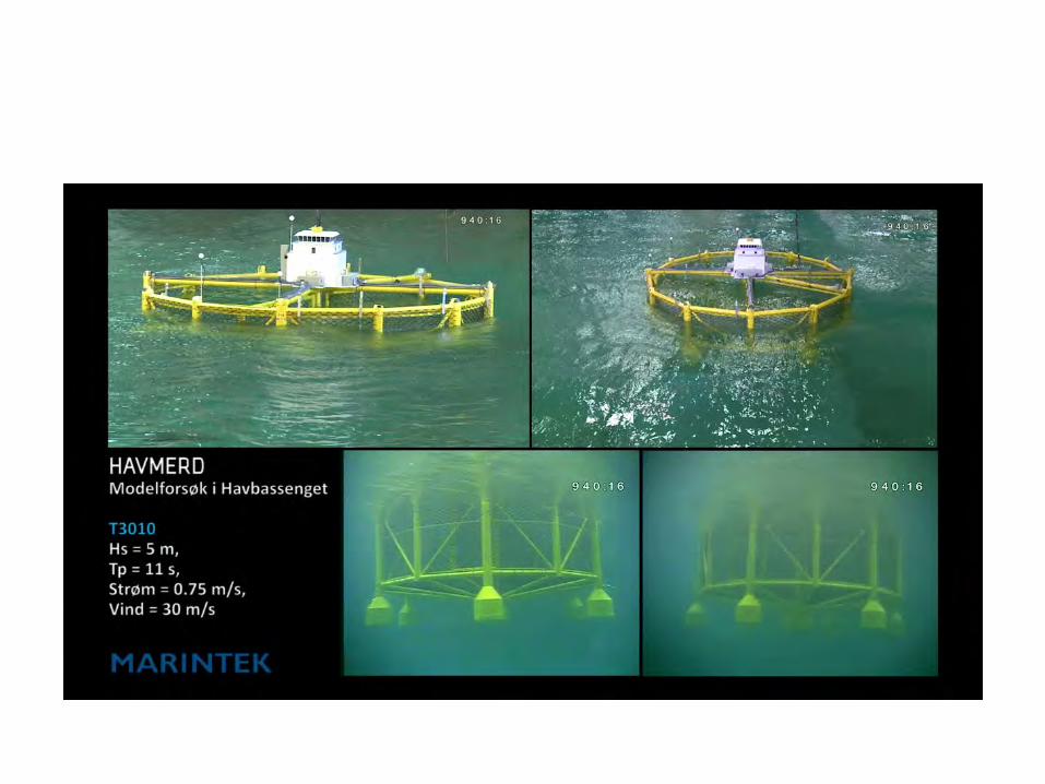
Movie Shown here
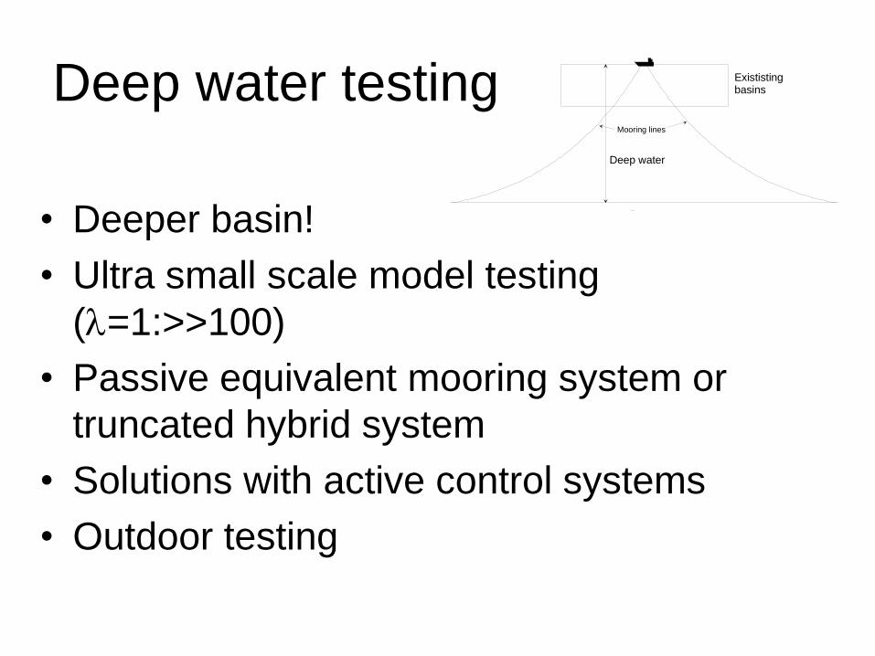
Deep water testing
• Deeper basin! • Ultra small scale model testing
(λ=1:>>100) • Passive equivalent mooring system or
truncated hybrid system • Solutions with active control systems • Outdoor testing
Exististing basins
Deep water
Mooring lines
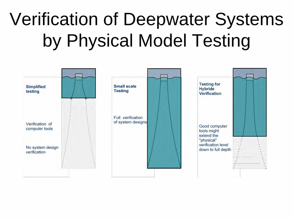
Verification of Deepwater Systems by Physical Model Testing
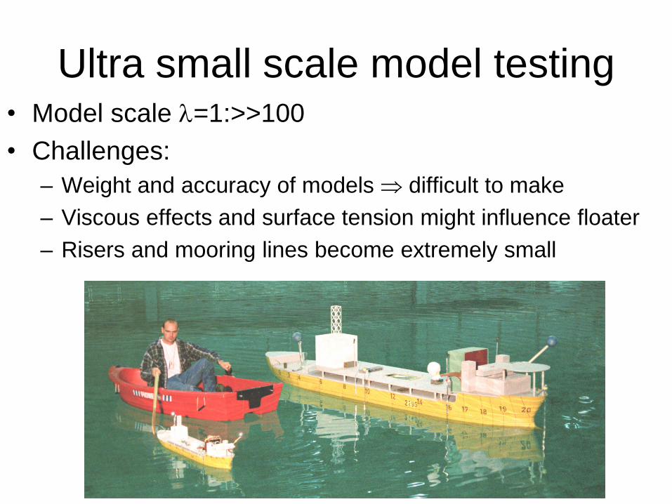
Ultra small scale model testing • Model scale λ=1:>>100 • Challenges:
– Weight and accuracy of models ⇒ difficult to make – Viscous effects and surface tension might influence floater – Risers and mooring lines become extremely small
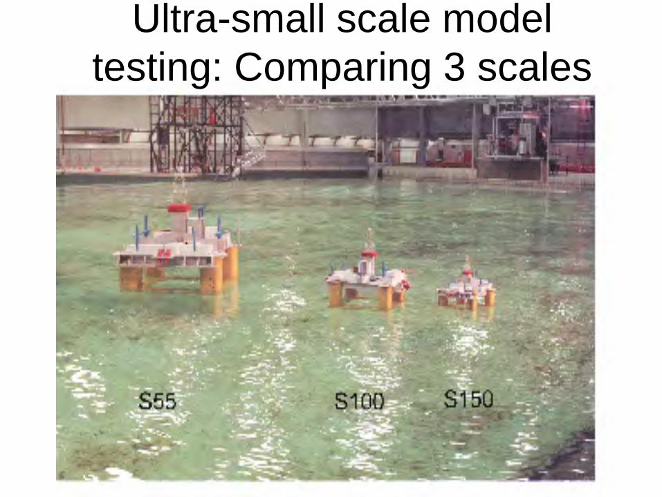
Ultra-small scale model testing: Comparing 3 scales
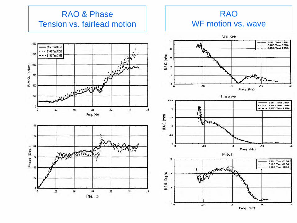
RAO & Phase Tension vs. fairlead motion
RAO WF motion vs. wave
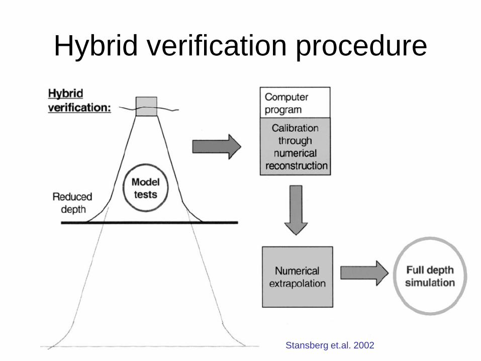
Hybrid verification procedure
Stansberg et.al. 2002
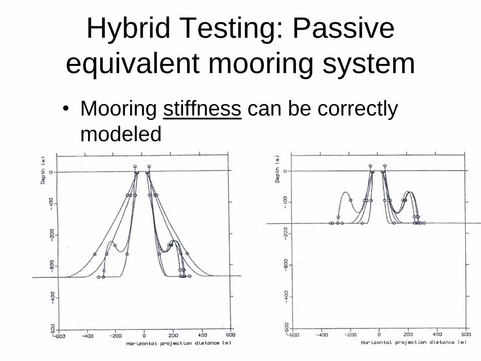
Hybrid Testing: Passive equivalent mooring system • Mooring stiffness can be correctly
modeled • Mooring and riser dynamics usually not
correctly represented
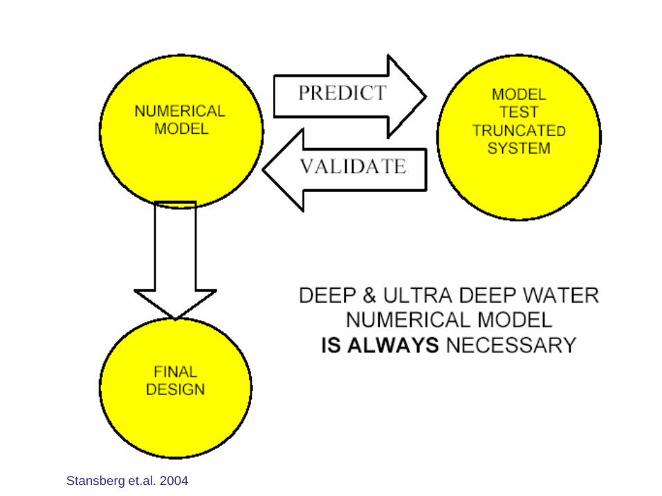
Stansberg et.al. 2004
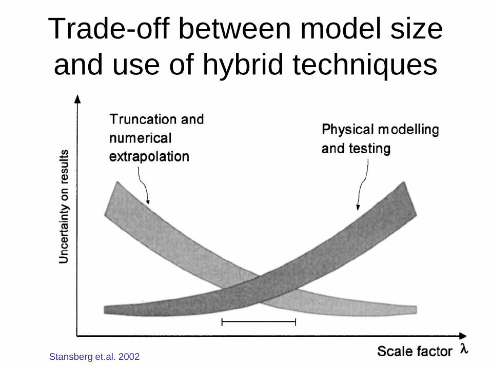
Trade-off between model size and use of hybrid techniques
Stansberg et.al. 2002
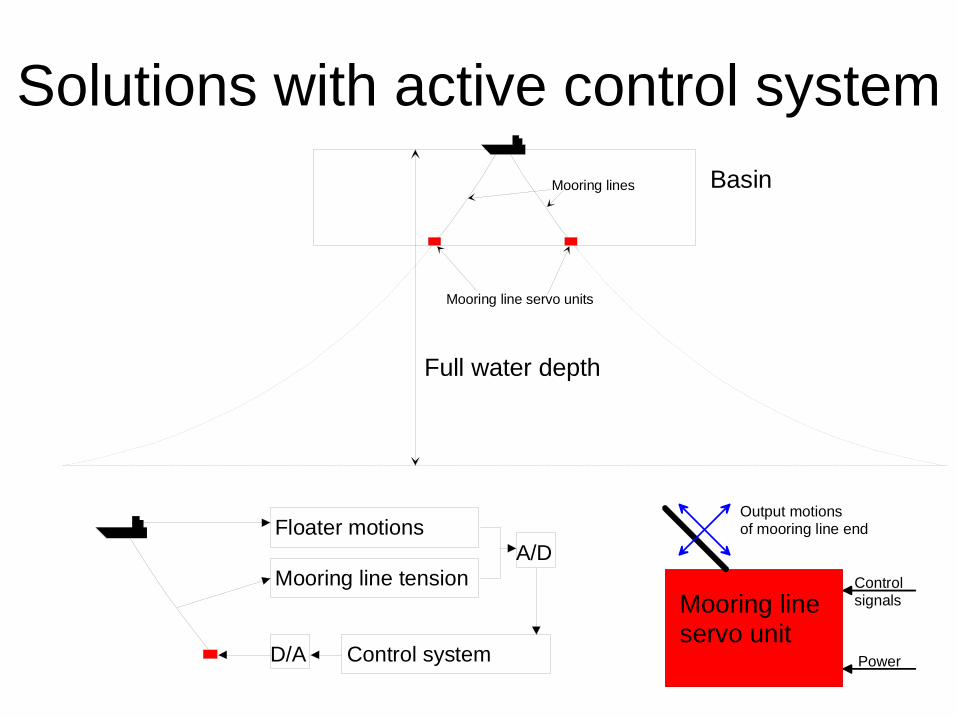
Solutions with active control system Exististing basins
Deep water
Mooring lines
Basin
Full water depth
Mooring lines
Mooring line servo units
Mooring line servo unit
Power
Controlsignals
Output motionsof mooring line endFloater motions
Mooring line tension
Control systemD/A
A/D
Outdoors testing • Verification tests with complete system cannot
be done outdoors, due to lack of control of environment
• Phenomenal studies can be done, provided measurement of both environment and responses
• Have been done for investigation of riser Vortex-Induced Vibrations & inteference – Hanøytangen – Skarnsundet
Testing of Marine Operations (1) • Testing of critical events of the marine
operation, e.g. an object in the splash zone, near sea bed, impact at guidepines
• Determination of environmental limits for specific operations (Wind, Waves & Current)
• Trying out of different procedures • Typical operations
– Heavy lift – Installation of bottom equipment – Pipe laying – Towing operations
Testing of Marine Operations (2)
• Determination hydrodynamic coefficients used as input to numerical studies – Free Oscillation Tests – Forced Motion tests
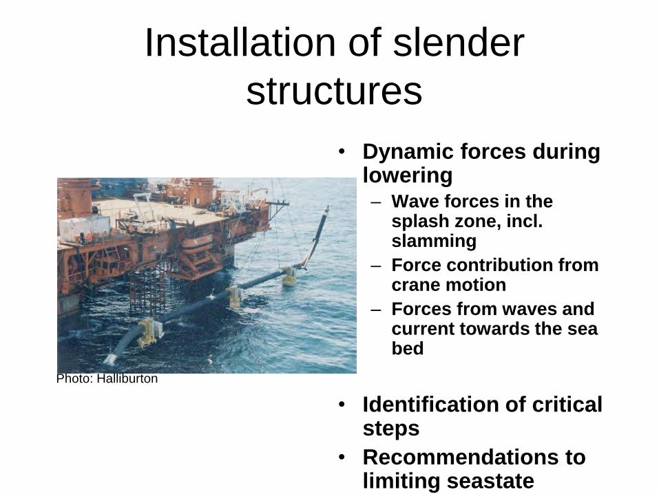
Installation of slender structures
• Dynamic forces during lowering – Wave forces in the
splash zone, incl. slamming
– Force contribution from crane motion
– Forces from waves and current towards the sea bed
• Identification of critical
steps • Recommendations to
limiting seastate
Photo: Halliburton
512384
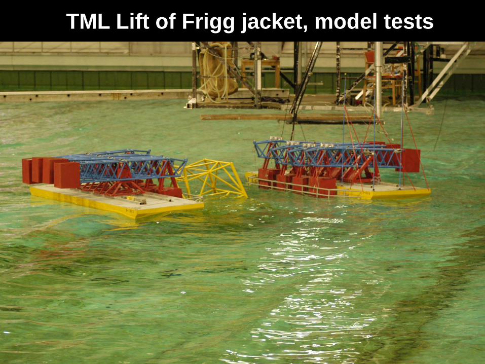
TML Lift of Frigg jacket, model tests
47
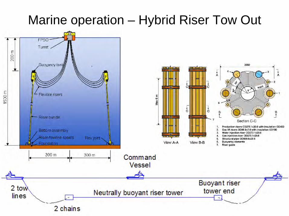
Marine operation – Hybrid Riser Tow Out
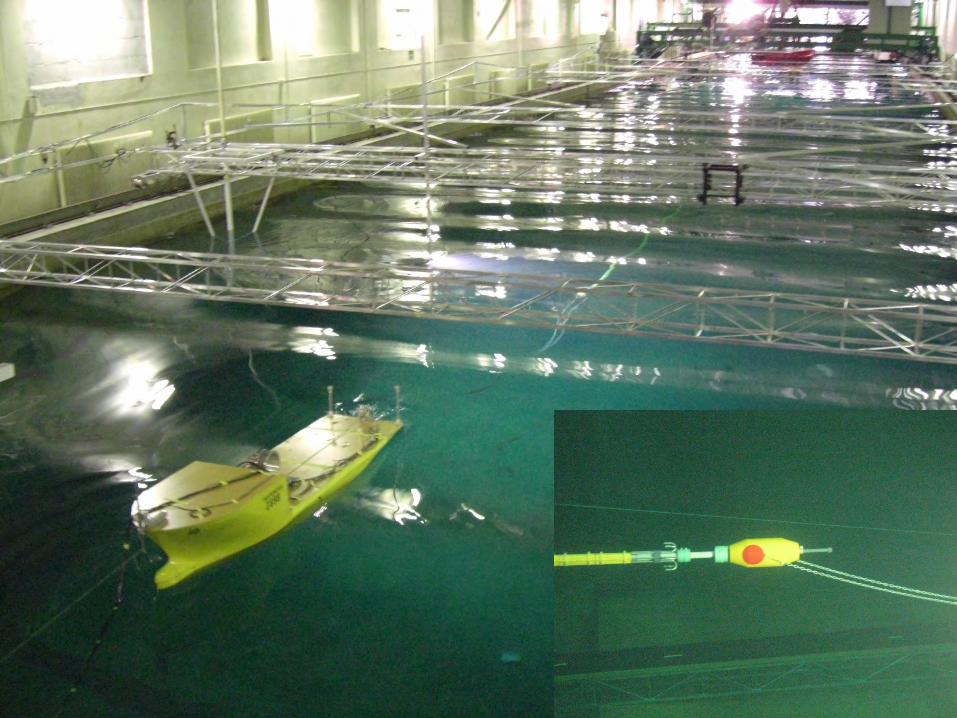
48
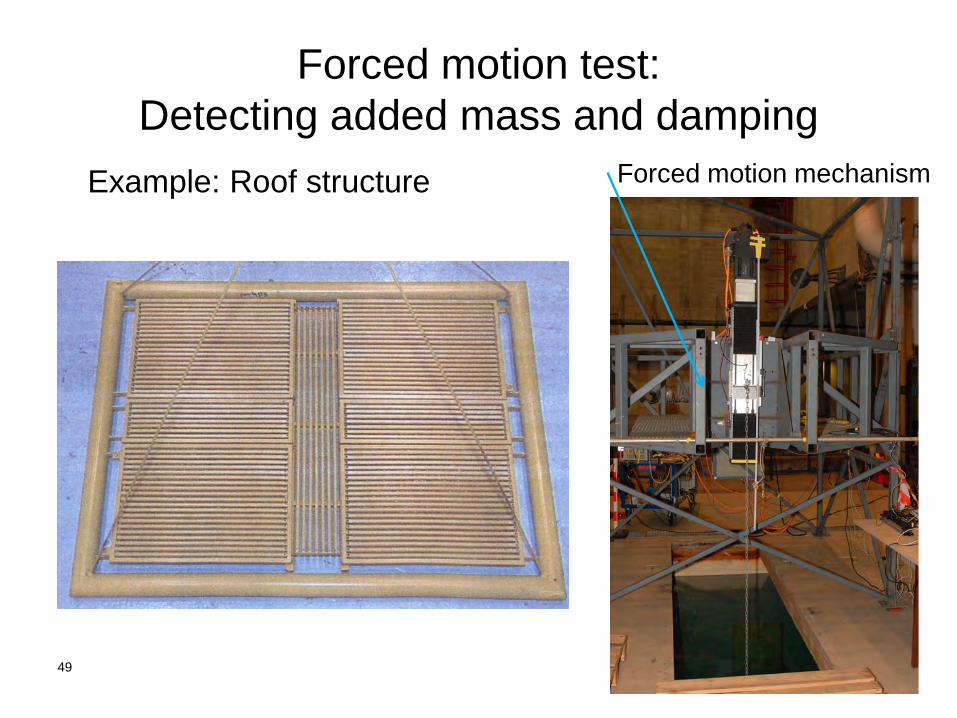
Forced motion test: Detecting added mass and damping
49
Example: Roof structure Forced motion mechanism
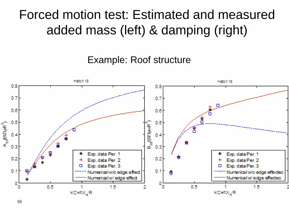
Forced motion test: Estimated and measured added mass (left) & damping (right)
50
Example: Roof structure
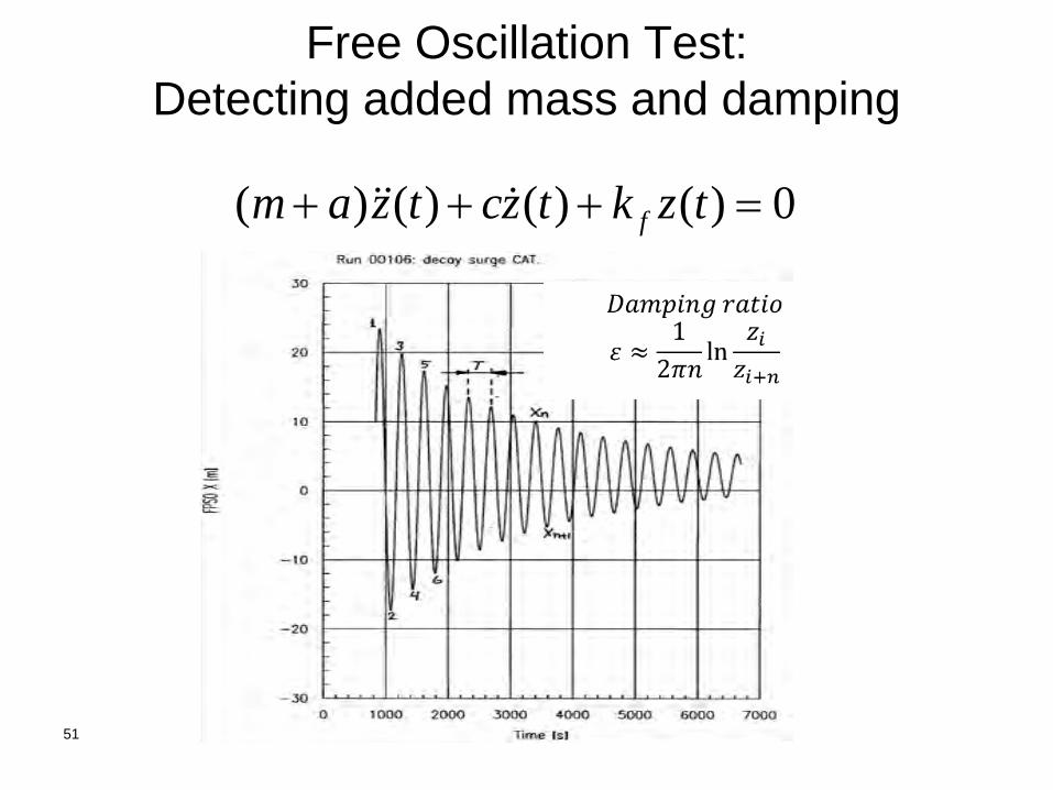
Free Oscillation Test: Detecting added mass and damping
51
0)()()()( =+++ tzktzctzam f
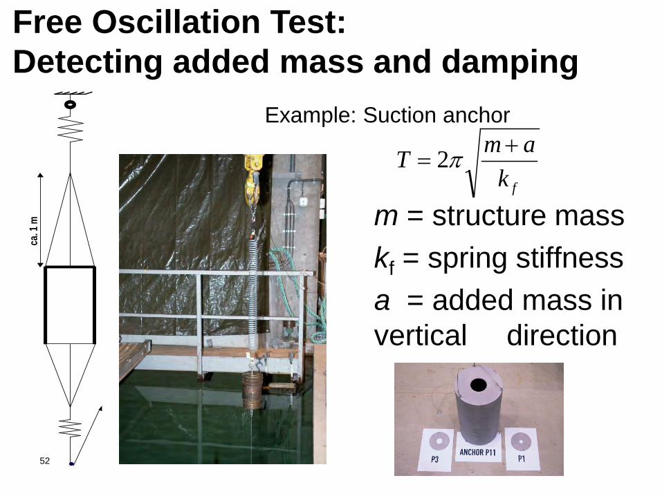
Example: Suction anchor
m = structure mass kf = spring stiffness a = added mass in vertical direction
52
fkamT +
= π2
ca. 1
mFree Oscillation Test: Detecting added mass and damping
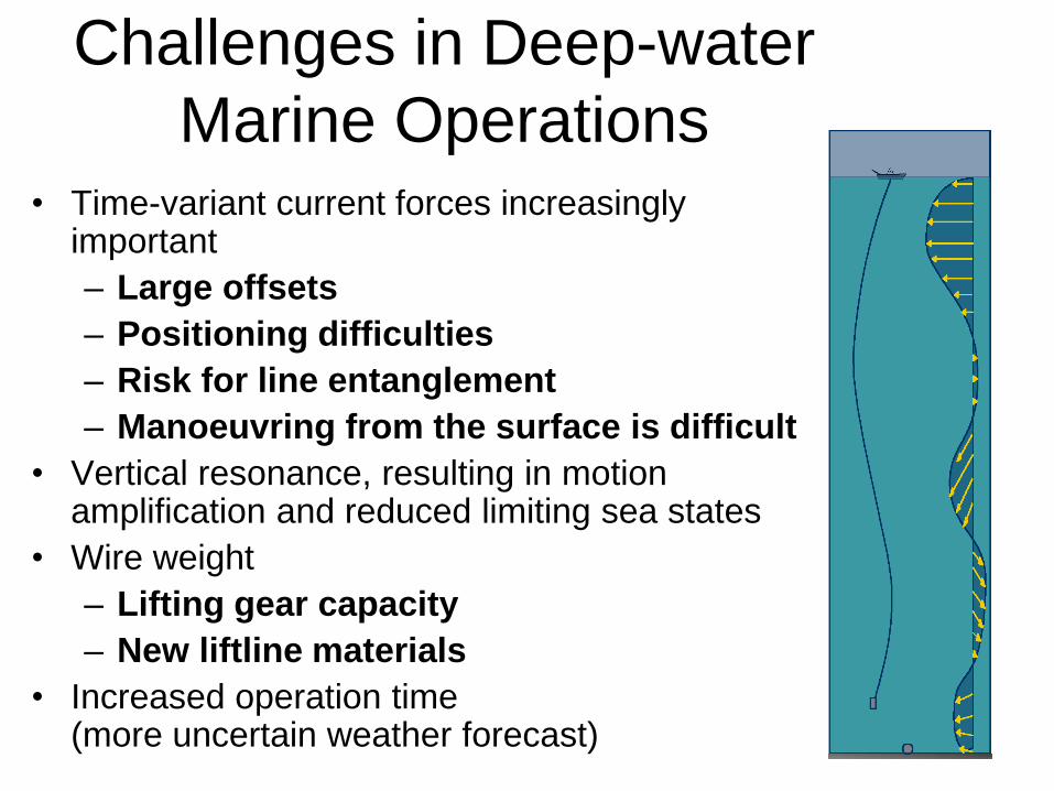
Challenges in Deep-water Marine Operations
• Time-variant current forces increasingly important – Large offsets – Positioning difficulties – Risk for line entanglement – Manoeuvring from the surface is difficult
• Vertical resonance, resulting in motion amplification and reduced limiting sea states
• Wire weight – Lifting gear capacity – New liftline materials
• Increased operation time (more uncertain weather forecast)
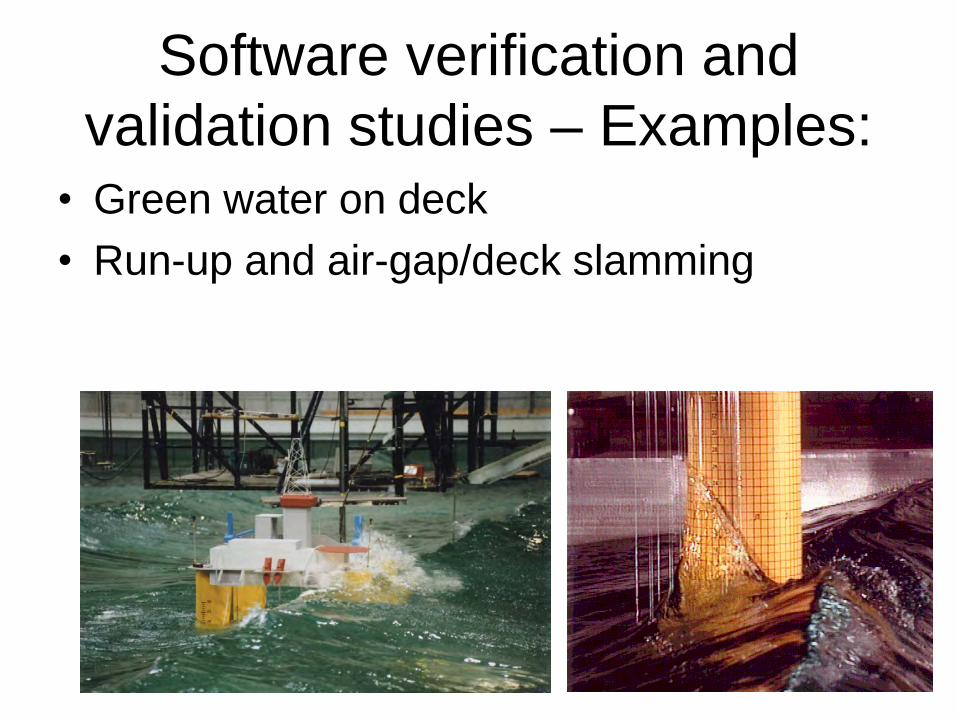
Software verification and validation studies – Examples:
• Green water on deck • Run-up and air-gap/deck slamming
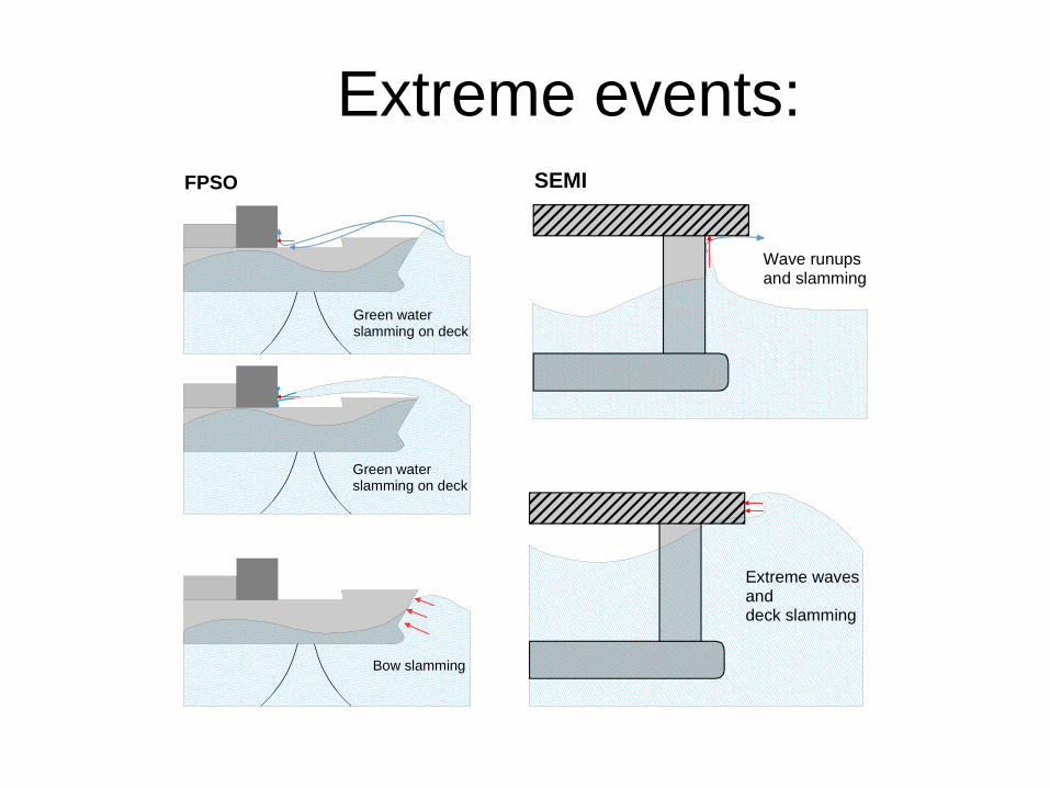
SEMI
Wave runups and slamming
Extreme wavesand deck slamming
Bow slamming
FPSO
Green waterslamming on deck
Green waterslamming on deck
Extreme events:
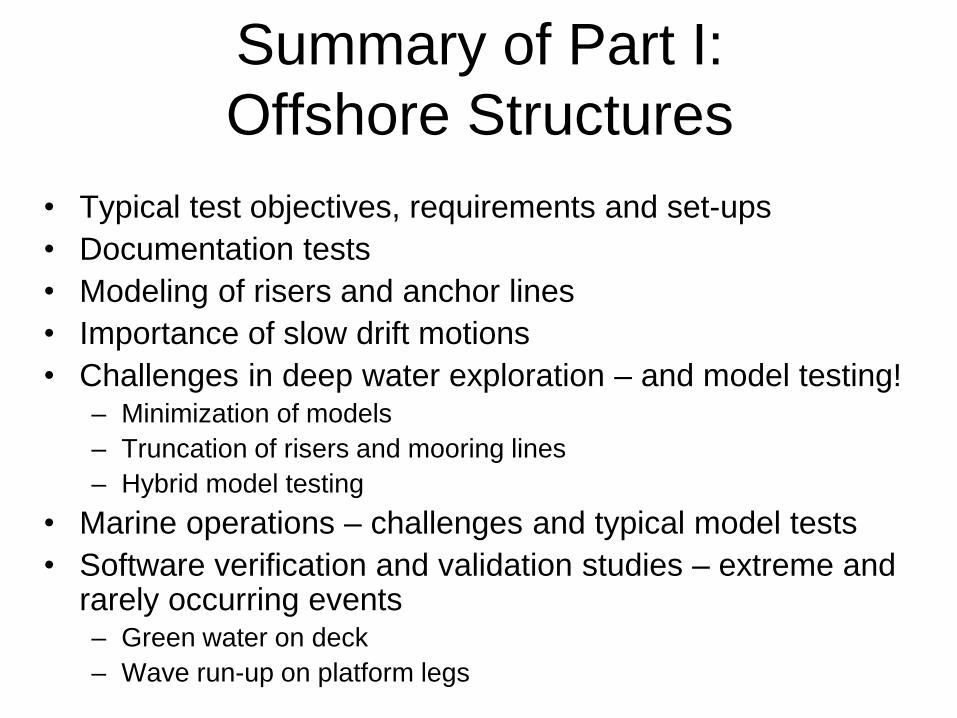
Summary of Part I: Offshore Structures
• Typical test objectives, requirements and set-ups • Documentation tests • Modeling of risers and anchor lines • Importance of slow drift motions • Challenges in deep water exploration – and model testing!
– Minimization of models – Truncation of risers and mooring lines – Hybrid model testing
• Marine operations – challenges and typical model tests • Software verification and validation studies – extreme and
rarely occurring events – Green water on deck – Wave run-up on platform legs
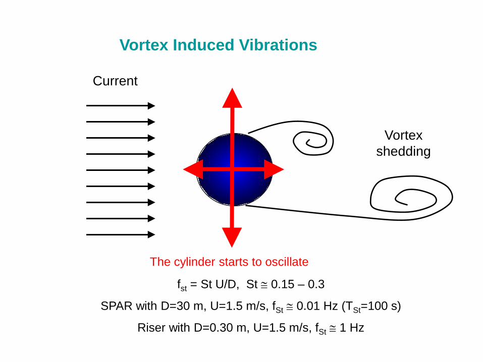
Current
The cylinder starts to oscillate
Vortex Induced Vibrations
fst = St U/D, St ≅ 0.15 – 0.3
SPAR with D=30 m, U=1.5 m/s, fSt ≅ 0.01 Hz (TSt=100 s)
Riser with D=0.30 m, U=1.5 m/s, fSt ≅ 1 Hz
Vortex shedding
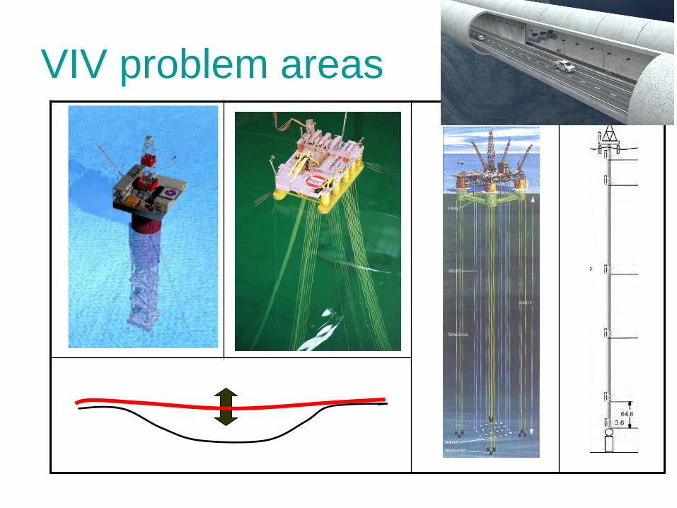
VIV problem areas Statens veivesen
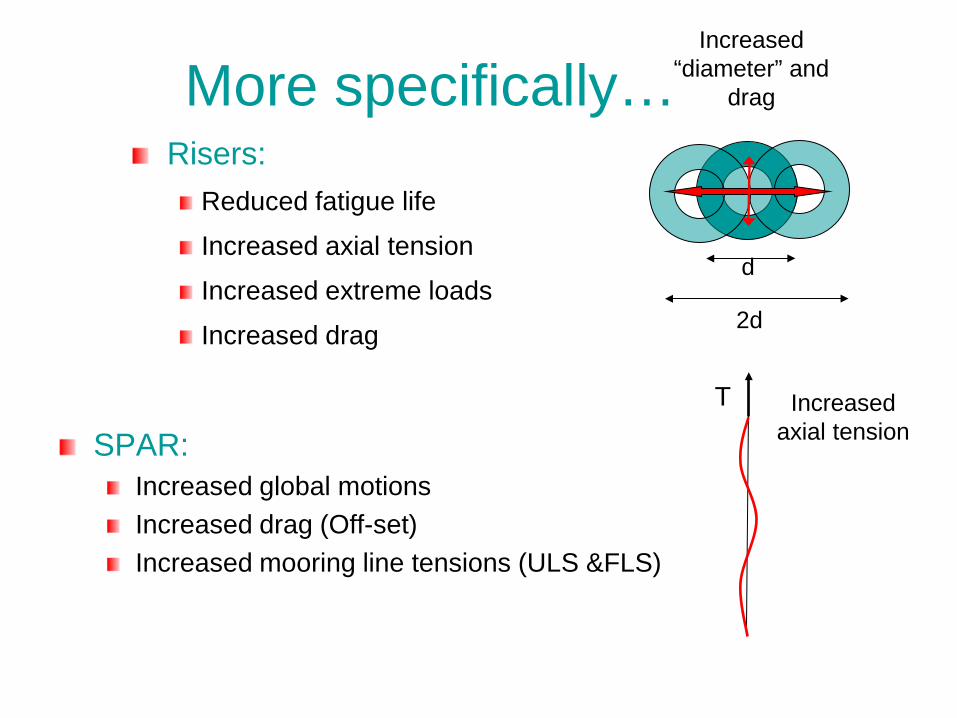
More specifically…
SPAR: Increased global motions Increased drag (Off-set) Increased mooring line tensions (ULS &FLS)
Risers: Reduced fatigue life
Increased axial tension
Increased extreme loads
Increased drag
Increased axial tension
T
Increased “diameter” and
drag
2d
d
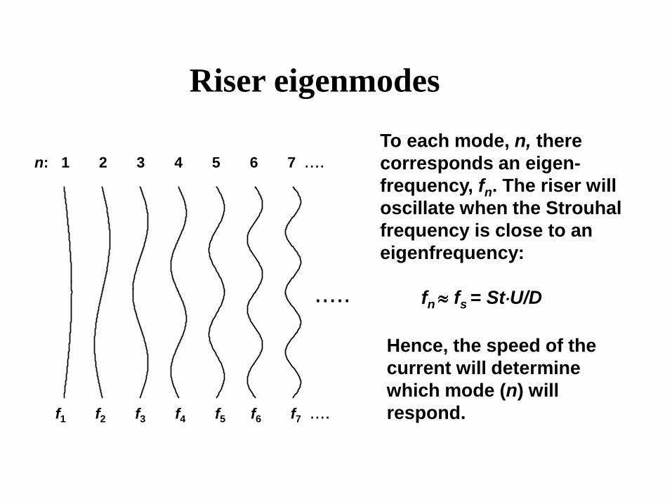
Riser eigenmodes To each mode, n, there corresponds an eigen-frequency, fn. The riser will oscillate when the Strouhal frequency is close to an eigenfrequency: fn ≈ fs = St⋅U/D
Hence, the speed of the current will determine which mode (n) will respond.
n: 1 2 3 4 5 6 7 ....
.....
f1 f2 f3 f4 f5 f6 f7 ....
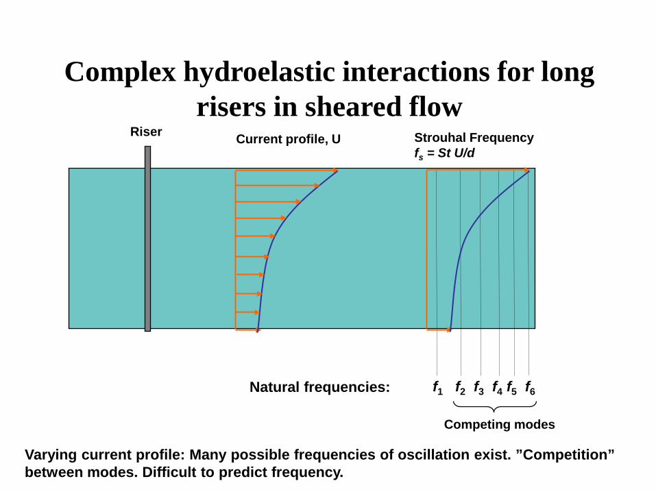
Complex hydroelastic interactions for long risers in sheared flow
f1 f2 f3 f4 f5 f6
Strouhal Frequency fs = St U/d
Current profile, U Riser
Natural frequencies:
Competing modes
Varying current profile: Many possible frequencies of oscillation exist. ”Competition” between modes. Difficult to predict frequency.
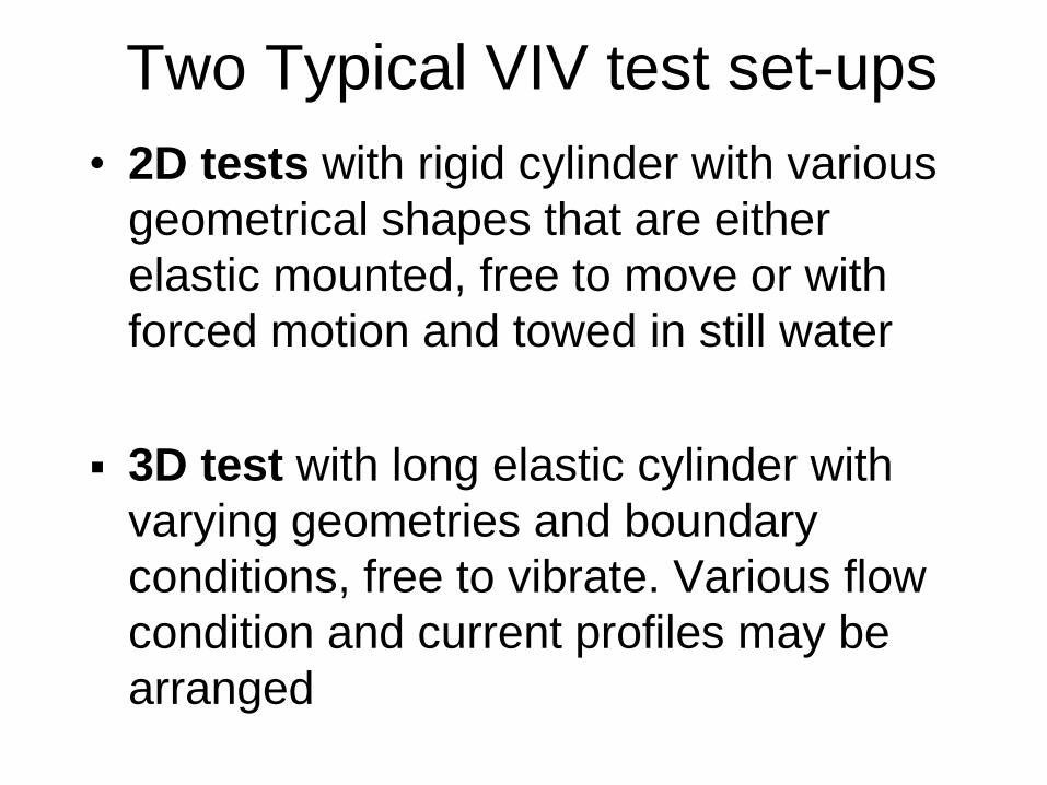
Two Typical VIV test set-ups • 2D tests with rigid cylinder with various
geometrical shapes that are either elastic mounted, free to move or with forced motion and towed in still water
3D test with long elastic cylinder with varying geometries and boundary conditions, free to vibrate. Various flow condition and current profiles may be arranged
Typical Test Requirements • Well defined flow with small (neglectable) turbulence • Correct (e.g. Froude) scaled models • Accurate measurements of motion / deformation /
reaction forces • For free vibration test: low and documented
“material” damping • No unintentionally interference between VIV
response frequencies (≈Strouhal frequencies) and eigen frequencies of test rig
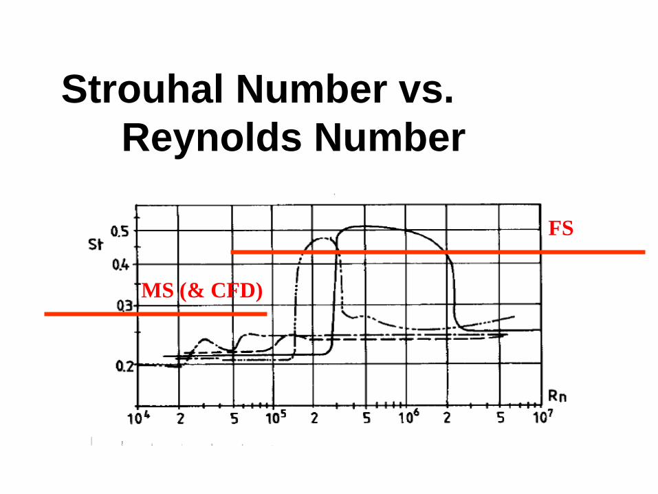
Strouhal Number vs. Reynolds Number
MS (& CFD)
FS
Rigid cylinder section (2D) tests (L/D = 10-25)
• Determine hydrodynamic coefficients Study in-line and/or cross-flow
oscillations Study effect of VIV suppression
devices
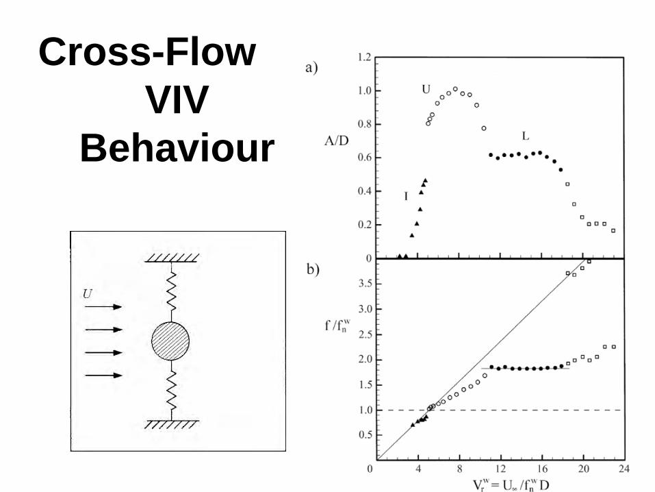
Cross-Flow VIV
Behaviour
Susan Swithenbank (post doc. at CeSOS)
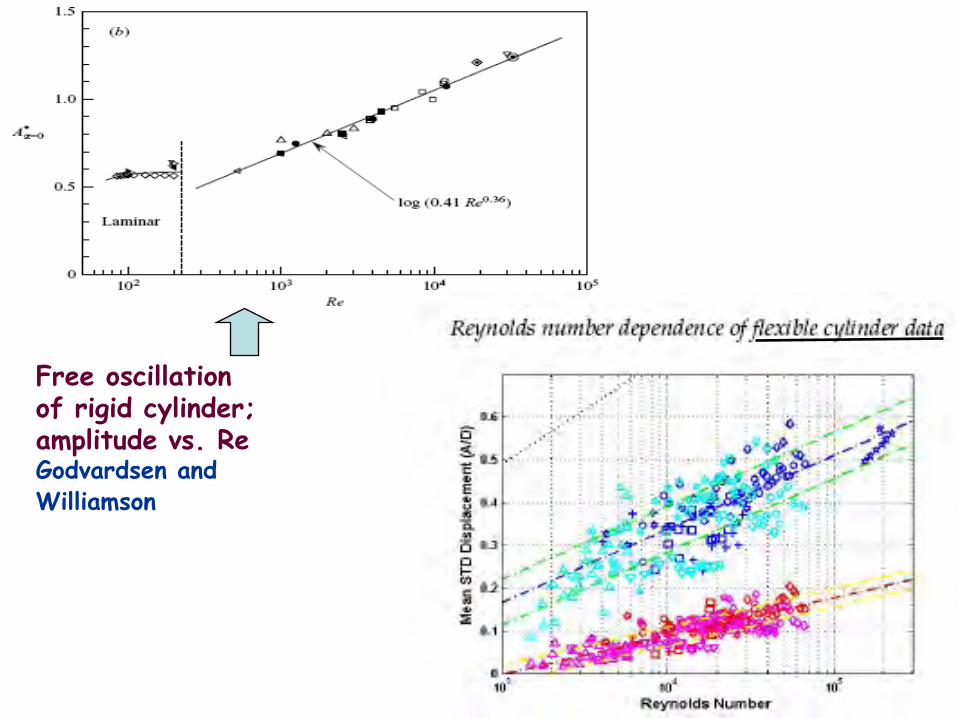
Free oscillation of rigid cylinder; amplitude vs. Re Godvardsen and Williamson
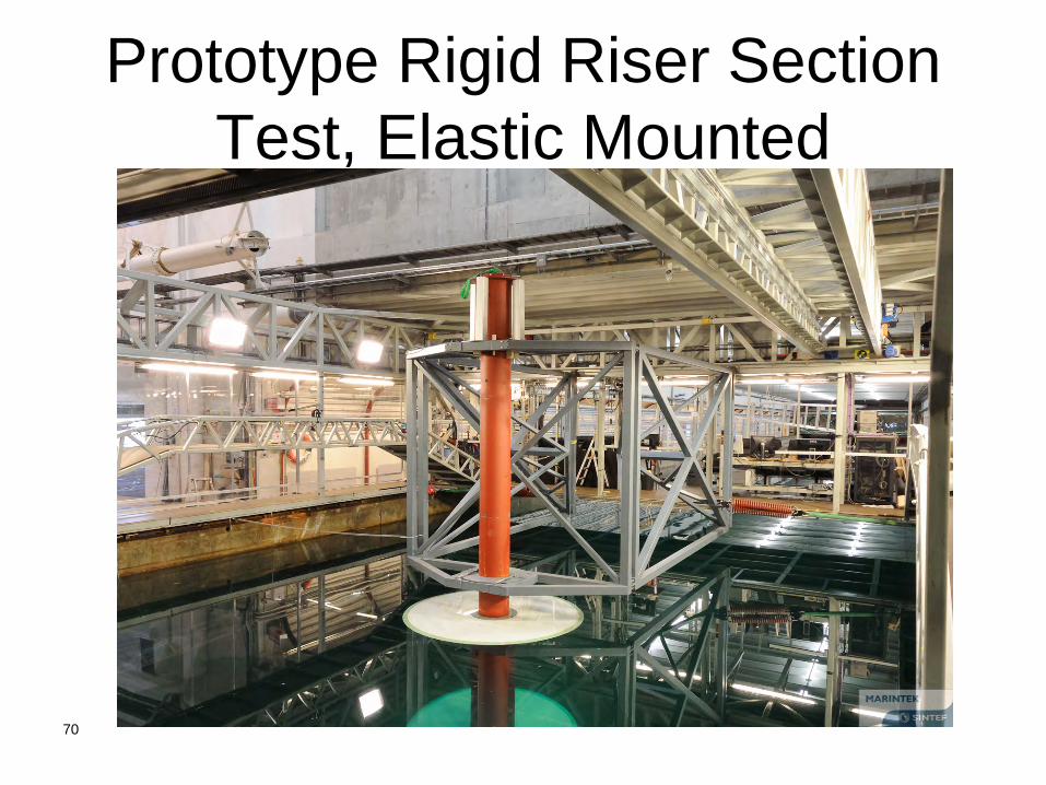
Prototype Rigid Riser Section Test, Elastic Mounted
70
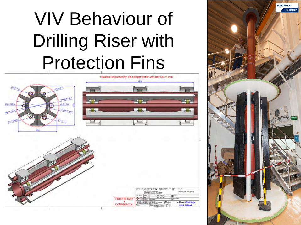
VIV Behaviour of Drilling Riser with Protection Fins
71
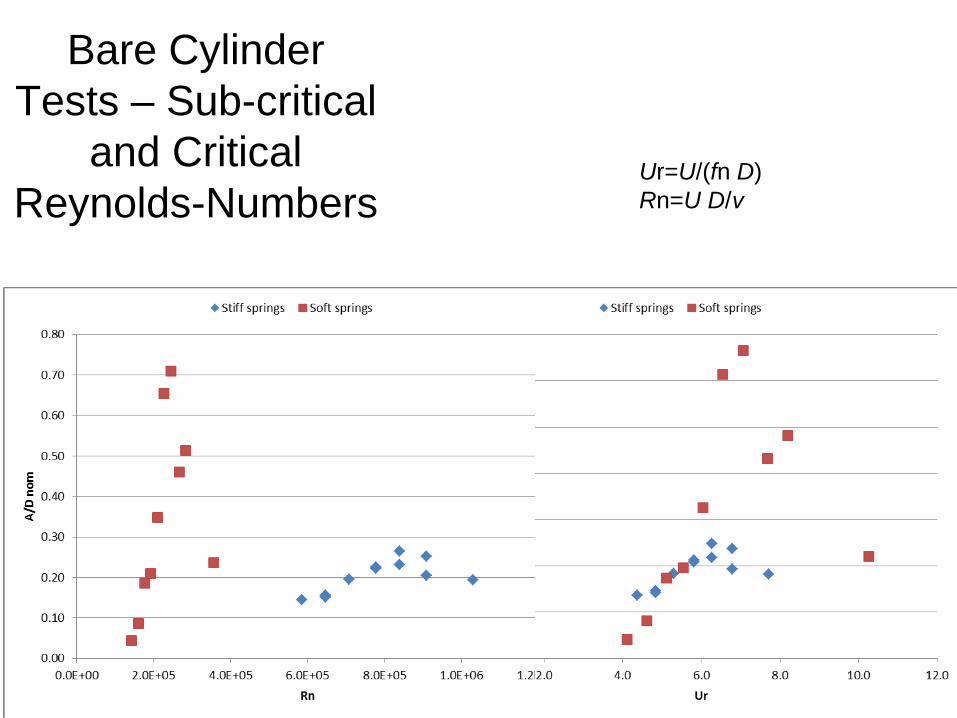
Bare Cylinder Tests – Sub-critical
and Critical Reynolds-Numbers
72
Ur=U/(fn D) Rn=U D/ν
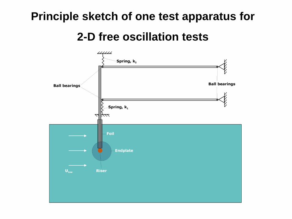
Principle sketch of one test apparatus for
2-D free oscillation tests
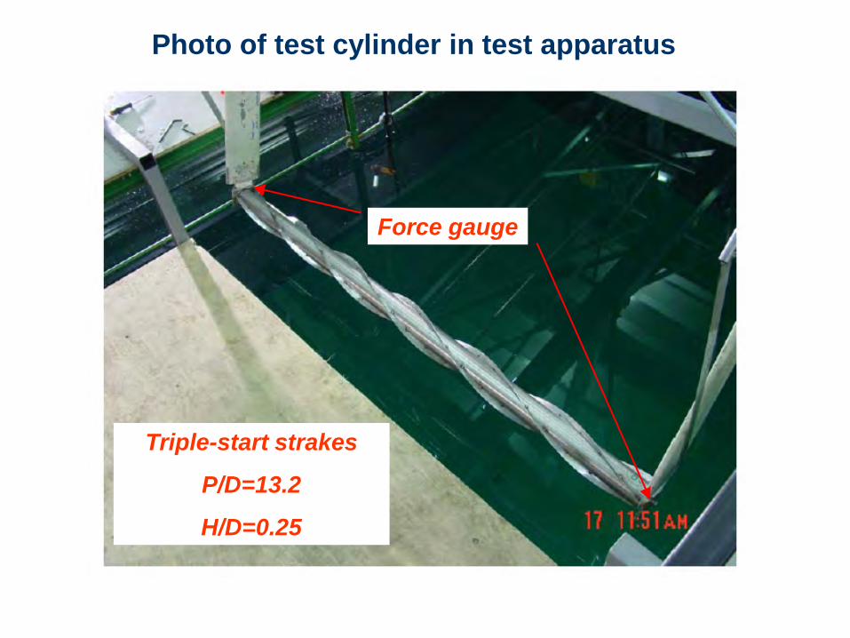
Triple-start strakes
P/D=13.2
H/D=0.25
Force gauge
Photo of test cylinder in test apparatus
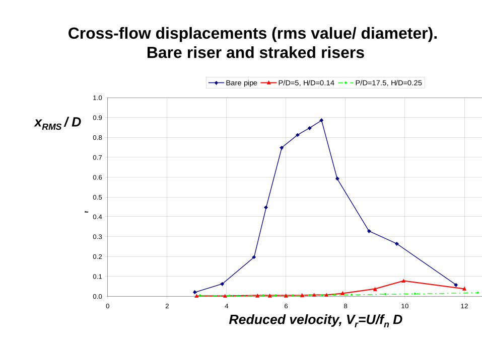
Cross-flow displacements (rms value/ diameter). Bare riser and straked risers
0.0
0.1
0.2
0.3
0.4
0.5
0.6
0.7
0.8
0.9
1.0
0 2 4 6 8 10 12
Vr [-]
rms
x/D
[-]
Bare pipe P/D=5, H/D=0.14 P/D=17.5, H/D=0.25
xRMS / D
Reduced velocity, Vr=U/fn D
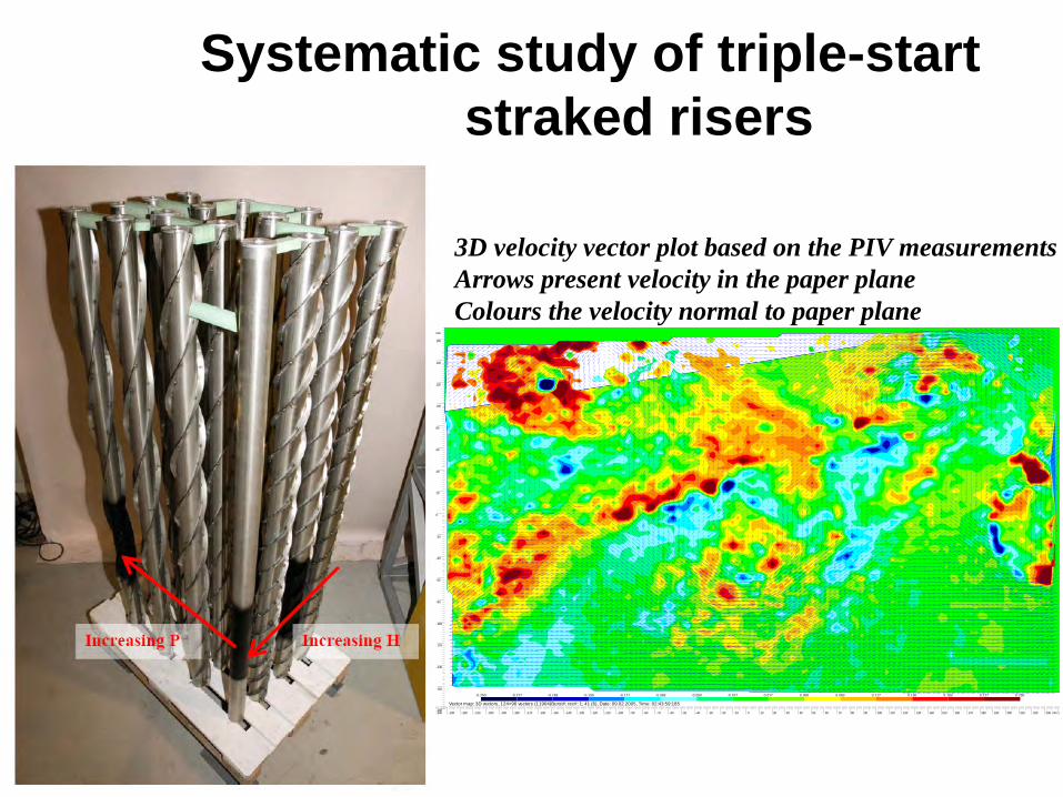
Systematic study of triple-start straked risers
-240
-230
-220
-210
-200
-190
-180
-170
-160
-150
-140
-130
-120
-110
-100
-90
-80
-70
-60
-50
-40
-30
-20
-10
0
10
20
30
40
50
60
70
80
90
100
110
120
130
140
150
160
170
180
190
200
210
220
230
2
mm
-180
-160
-140
-120
-100
-80
-60
-40
-20
0
20
40
60
80
100
120
140
160
mm
-0.250 -0.217 -0.183 -0.150 -0.117 -0.083 -0.050 -0.017 0.017 0.050 0.083 0.117 0.150 0.183 0.217 0.250
Vector map: 3D vectors, 124×96 vectors (11904)Burst#; rec#: 1; 41 (6), Date: 09.02.2005, Time: 02:43:59:185
3D velocity vector plot based on the PIV measurements Arrows present velocity in the paper plane Colours the velocity normal to paper plane
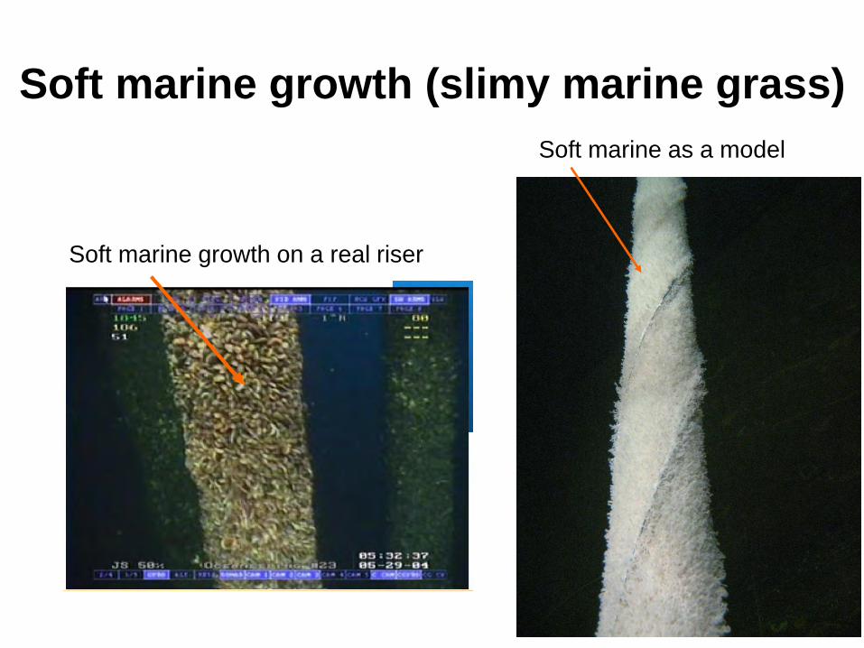
Soft marine growth (slimy marine grass)
Soft marine growth on a real riser
Soft marine as a model
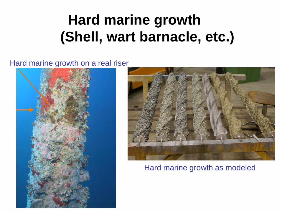
Hard marine growth (Shell, wart barnacle, etc.)
Hard marine growth on a real riser
Hard marine growth as modeled
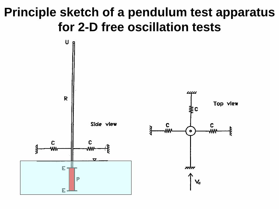
Principle sketch of a pendulum test apparatus for 2-D free oscillation tests
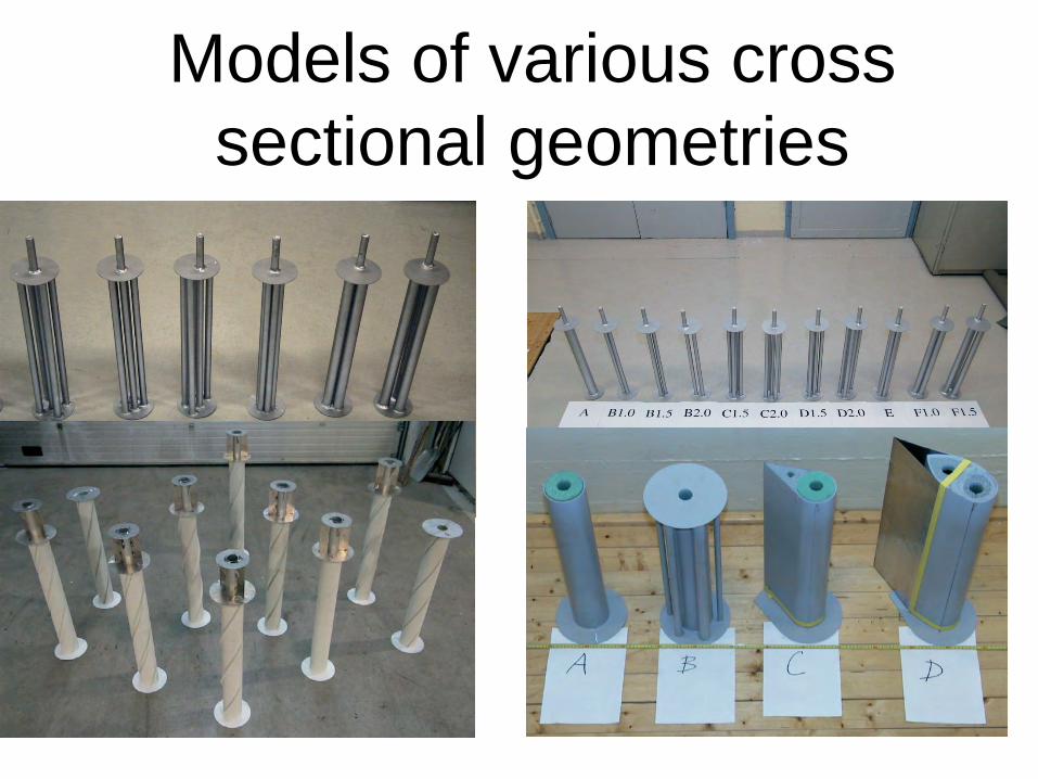
Models of various cross sectional geometries
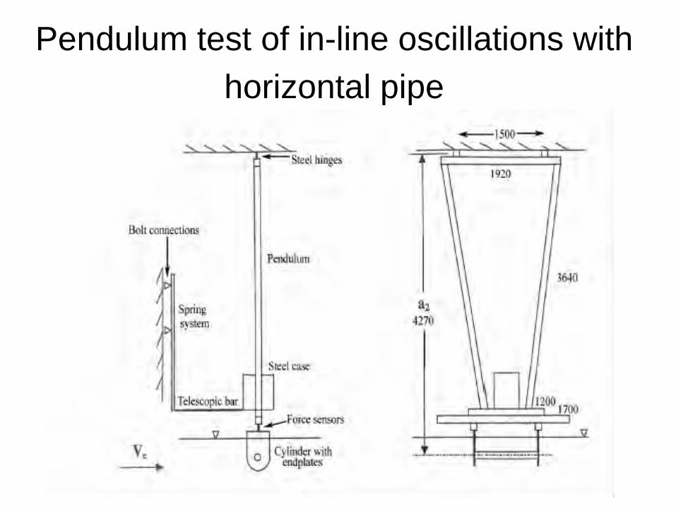
Pendulum test of in-line oscillations with horizontal pipe
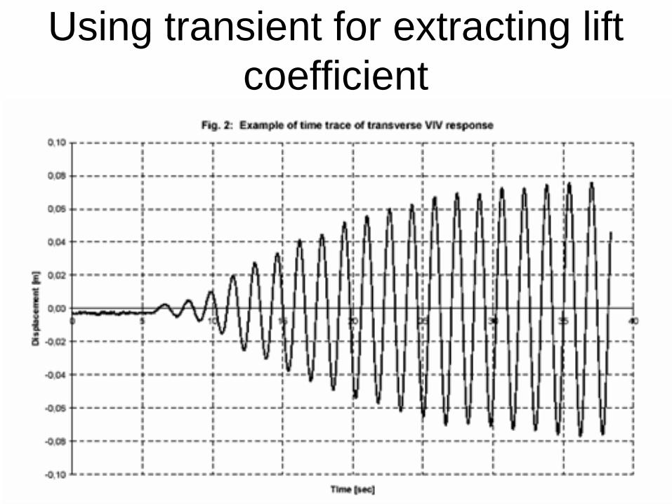
Using transient for extracting lift coefficient
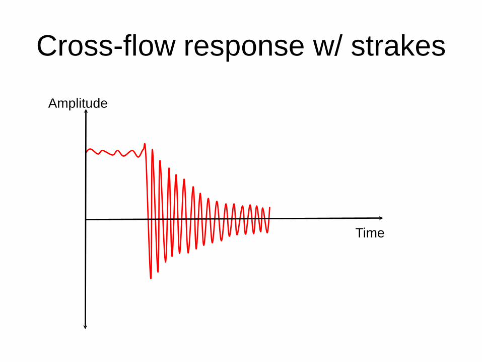
Cross-flow response w/ strakes
Amplitude
Time
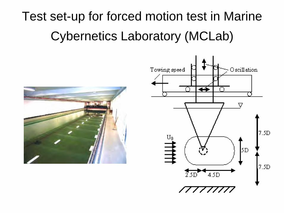
Test set-up for forced motion test in Marine Cybernetics Laboratory (MCLab)
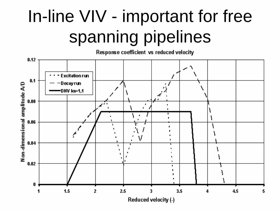
In-line VIV - important for free spanning pipelines
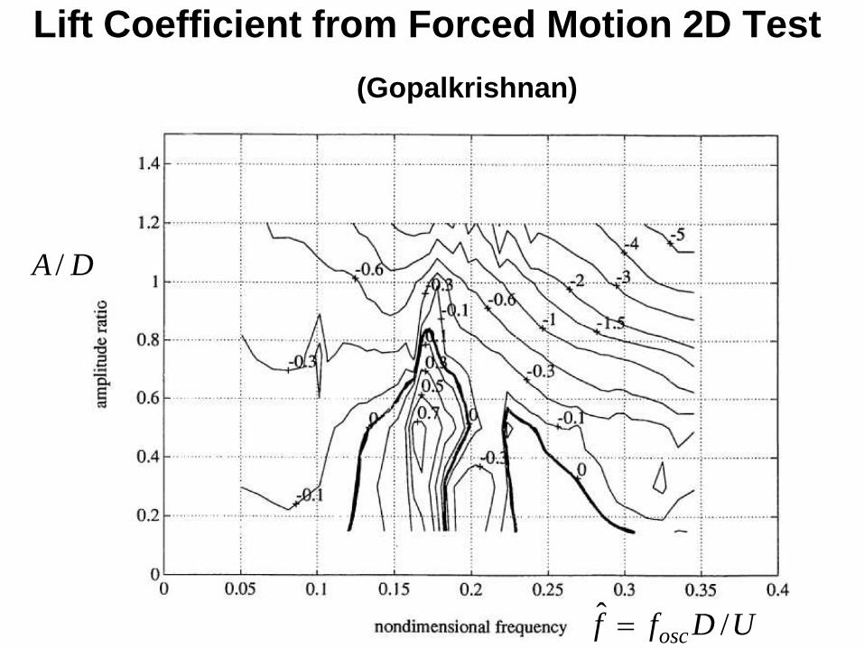
Lift Coefficient from Forced Motion 2D Test (Gopalkrishnan)
/A D
ˆ /oscf f D U=
Flexible beam (3D) tests
3-D Pipe & Umbilical Tests (L/D =50-150) – To study multimode oscillations of free
spanning pipelines in uniform current 3-D Riser Tests (L/D > 300)
– To study multimode oscillations in uniform and sheared current
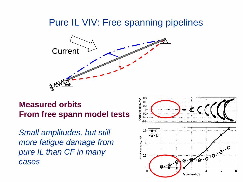
Pure IL VIV: Free spanning pipelines
Current
Measured orbits From free spann model tests
Small amplitudes, but still more fatigue damage from pure IL than CF in many cases
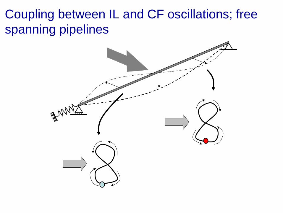
Coupling between IL and CF oscillations; free spanning pipelines
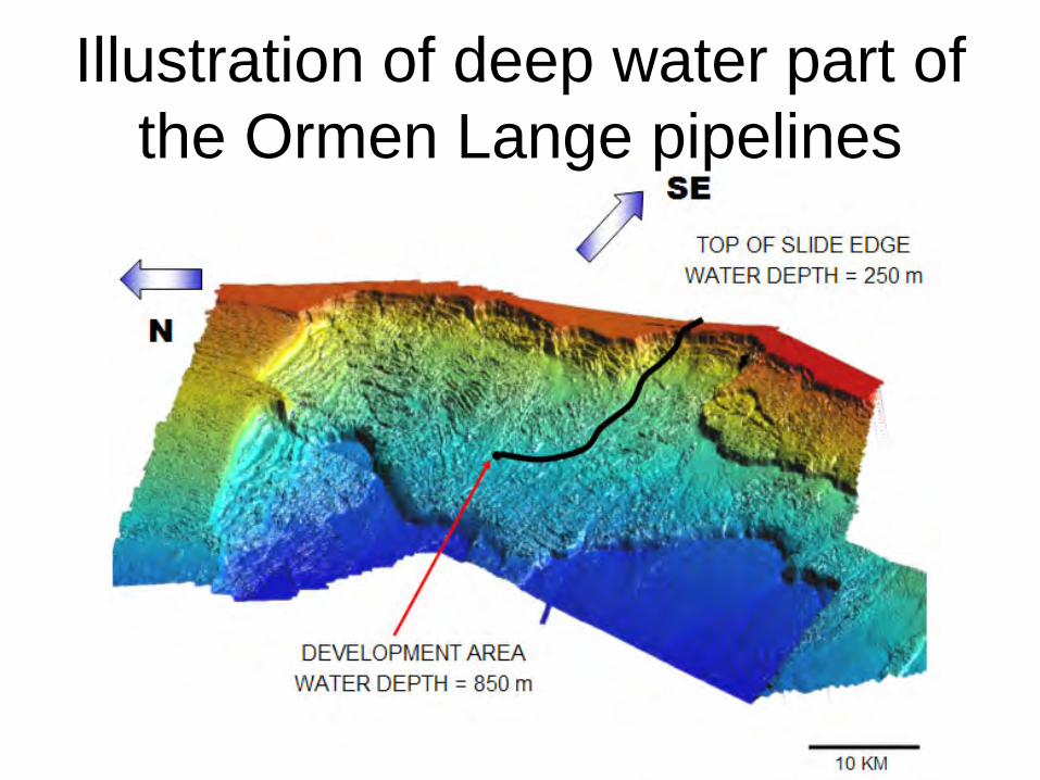
Illustration of deep water part of the Ormen Lange pipelines
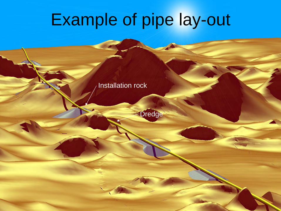
Example of pipe lay-out
Dredge
Installation rock
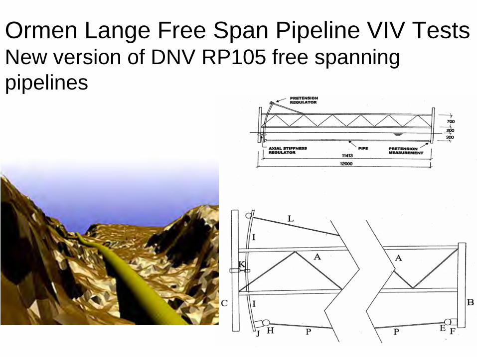
Ormen Lange Free Span Pipeline VIV Tests New version of DNV RP105 free spanning pipelines
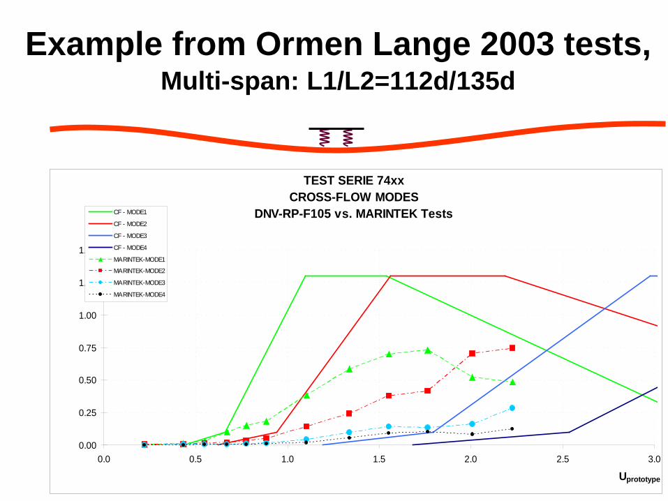
Example from Ormen Lange 2003 tests, Multi-span: L1/L2=112d/135d
TEST SERIE 74xxCROSS-FLOW MODES
DNV-RP-F105 vs. MARINTEK Tests
0.00
0.25
0.50
0.75
1.00
1.25
1.50
0.0 0.5 1.0 1.5 2.0 2.5 3.0
Uprototype
A/D
CF - MODE1
CF - MODE2
CF - MODE3
CF - MODE4
MARINTEK-MODE1
MARINTEK-MODE2
MARINTEK-MODE3
MARINTEK-MODE4
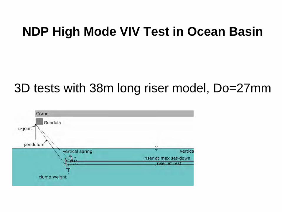
NDP High Mode VIV Test in Ocean Basin
3D tests with 38m long riser model, Do=27mm
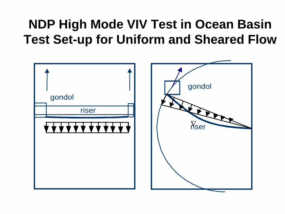
NDP High Mode VIV Test in Ocean Basin Test Set-up for Uniform and Sheared Flow
Riser model Clump weight
∇
riser
gondol
riser
gondol
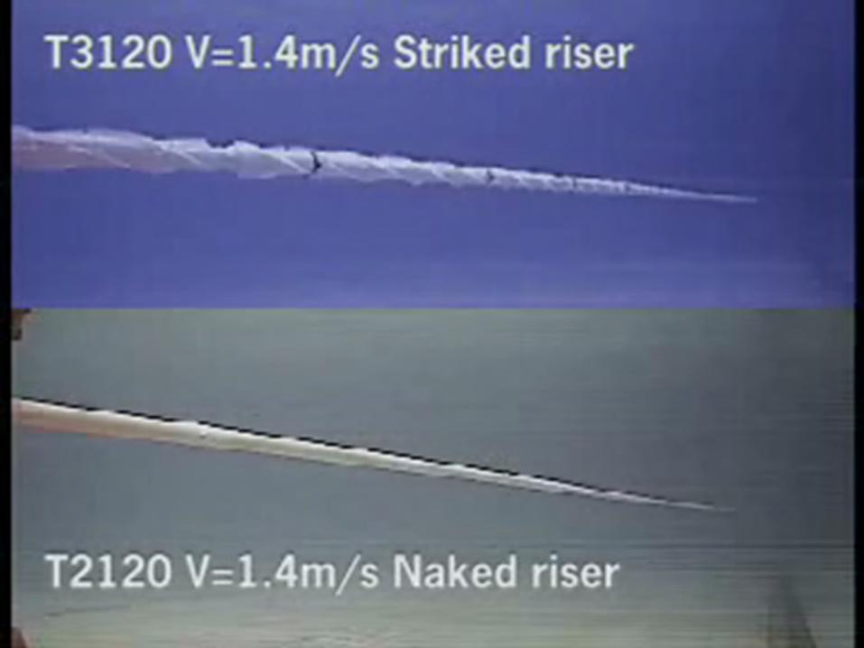
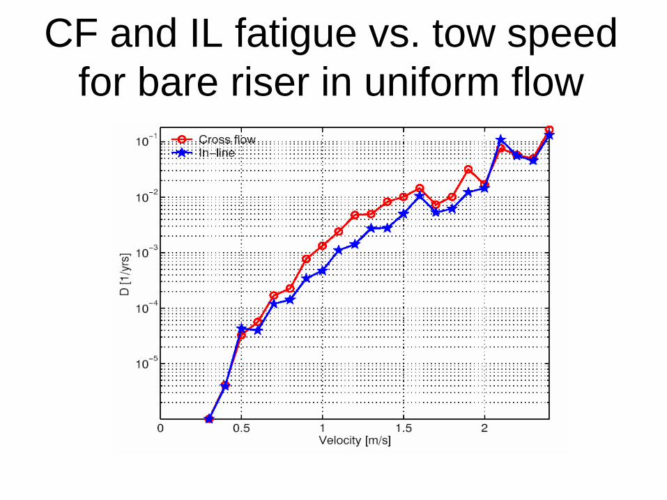
CF and IL fatigue vs. tow speed for bare riser in uniform flow
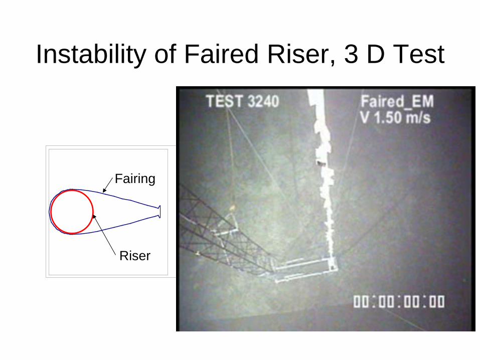
Instability of Faired Riser, 3 D Test
Fairing
Riser
Summary of Part II: Vortex Induced Vibrations
• Phenomenon & problem areas • Objective of testing
– VIV behavior – Suppression devices – Determine empirical coefficients used as input to prediction codes – Establish experimental data used for validation of semi-empirical
codes and CFD codes • Typical test set-ups
– 2D tests – 3D tests