Embed Size (px)
Citation preview

CATALOG NO.: TFPC-9SUPERCEDES: TFPC-4
260 NORTH ELM ST. WESTFIELD, MA 01085 (413) 564-5540 • FAX: (413) 562-5311
www.sterlinghvac.com
HVAC PRODUCTS
MODEL “TF”, “RF” & “SF”GAS-FIRED TUBULAR
UNIT HEATERSREPLACEMENT PARTS
CATALOG
INDEXWARRANTY INFORMATION – RETURN GOODS ........................................................................2CONVERSION KITS ......................................................................................................................3SF-30/75 SEPARATED COMBUSTION REPLACEMENT PARTS .............................................4, 5RF/TF-30/90 LOW PROFILE REPLACEMENT PARTS ............................................................6, 7TF-100/400 REPLACEMENT PARTS ............................................................................ 8, 9, 10, 11OPTIONAL PARTS .......................................................................................................................12UNITS WITH HOT SURFACE IGNITION .....................................................................................13TERMS .........................................................................................................................................15
IMPORTANTWHEN ORDERING PARTS, PLEASE
SPECIFY UNIT MODEL NO. AND SERIAL NO.
3/10

2
IMPORTANT WARRANTY INFORMATION
If you are ordering a replacement part for a unit which you believe to be under warranty, the process is as follows:
• Provide Sterling with a description of the part or assembly needed and the model and serial number of the unit which experienced failure. If there is a question on the warranty, we can answer it at this point.
• We will enter your order and issue you a R.G.A. (Return Goods Authorization), if applicable, with instructions on how and where to send the defective parts.
• Your invoice will indicate “no charge” pending the return of the applicable defective parts. The invoice may list the R.G.A number and state: “a R.G.A has been issued. Reinvoicing will occur if no receipt in 30 days.” However, some parts are to be fi eld scrapped, which the invoice will state accordingly. If parts are received by us within the 30 days, and confi rmed as “defective in-warranty”, the transaction will be closed.
If we do not receive the parts within 30 days or our inspection reveals a non-warranty condition, then a subsequent invoice will be generated indicating the appropriate cost and we will no longer accept returns on that R.G.A.
In order to insure the orderly processing of your warranty claim it is MANDATORY that certain paper work accompany any and all goods returned to Sterling. It is also mandatory that goods be sent to the proper location.
In order to assure proper handling of these goods we insist that under all circumstances we must formally authorize the return of material to our various facilities. Any material returned without authorization will not be accepted.
In order to insure that your properly authorized returns are accepted at our plant, we ask that you clearly mark any and all shipping papers with an R.G.A. number; we will not accept shipments that do not clearly show R.G.A. number on the outside of the box or crate!
All returns to be shipped Freight Prepaid. Collect Shipmentswill not be accepted.
CONSULT OUR CUSTOMER SERVICE DEPT. FOR ANY REPLACEMENT PARTS NOT LISTED IN THIS PUBLICATION. LIMITED AVAILABILITY ON
CERTAIN OBSOLETE EQUIPMENT.TEL. 413-564-5540 FAX# 413-562-5311

3
For Units Manufactured Prior to November, 2006
90 J31R04091** J31R01872** 253R01873-001** J32R04840**‡ NLA - see below *
90 Fan Kits with ODP Motor 253R08358-001† 253R08358-002†‡ New Fan Kits***
Only* Fan Kits with TE Motor 253R08358-003† 253R08358-004†‡
For Units Manufactured After November, 2006
90 J31R04092 J31R01694 J32R08278 253R08290‡ J34R06999-102
CONVERSION KITS “RF/TF/SF” SERIES UNITSWITH DIRECT SPARK IGNITION SYSTEMS
(For units Manufactured January 1, 2006 and After)
CONVERTING FROM NAT. GAS TO LP GAS CONVERTING FROM LP GAS TO NAT. GAS
MODEL
NO.
RF/TF/SF-30/75 RF/TF-90 TF-100/400
MODEL
NO.
RF/TF/SF-30/75 RF/TF-90 TF-100/400
CONVERSION
KIT NO.261R08263†261R08264†
261R06951
CONVERSION
KIT NO.261R06957261R06961261R06952
†Universal Kit - converts both hot surface and direct spark ignition systems. Refer to Installation Manual for high altitude conversions (above 2,000 feet).
Fan Motor Fan Guard
Standard (ODP)Fan
(Propeller)
* Fan (propeller) replacements on units manufactured prior to November 2006 require a new Fan Kit. ** If fan is also to be replaced, use new fan kit for complete replacement. *** New Fan Kit contains: larger motor with 1/2" diameter shaft, fan and guard. FLA will increase to 6.7 amp.† New kits required to replace old 3/8" bore fan blade with new 1/2" bore fan blade, motor and guard.‡ OSHA guard required on all RF models; optional on TF models.
Optional (TE) Standard OSHAUnit Size
CONVERSION KITS “RF/TF/SF” SERIES UNITSWITH HOT SURFACE IGNITION CONTROLS
(For Units Manufactured Prior to January 1, 2006)
CONVERTING FROM NAT. GAS TO LP GAS CONVERTING FROM LP GAS TO NAT. GAS
MODEL
NO. RF/TF/SF-30/75 RF/TF-90 TF-100/400 TF-175/300**
MODEL
NO.
RF/TF/SF-30/75 RF/TF-90 TF-100/400 TF-350/400*
CONVERSION
KIT NO.261R08263†261R08264†
261R04867 261R04869
CONVERSION
KIT NO.261R04866261R05412261R04868261R04952
UNIT SIZE 90 ONLY (“RF” & “TF”) - FAN MOTOR/FAN GUARD/FAN
*For units manufactured prior to June 13, 2001, equippped with White Rodgers gas valve.**For units manufactured prior to June 13, 2001, equipped with 1/2" inlet and 3/4" outlet Honeywell smart valve.†Universal Kit - converts both hot surface and direct spark ignition systems. Refer to Installation Manual for high altitude conversions (above 2,000 feet).
4
MODEL “SF” 30-75 MBH “SEPARATED COMBUSTION” REPLACEMENT PARTS FOR UNITS WITH DIRECT SPARK IGNITION

5
4507R06687-001
J37R04684-060
252R06534
507R04698-060
261R06577-060
502R06420
J31R04091
J32R04840J34R06999-101261R04963-002
257R04587-011 (5)J26R01960 (5)
251R06610251R04719
251R04714251R06630
251R06615
251R06617
5507R06688-001
J37R04684-075
252R06535
507R04699-075
261R06577-075
502R06419
J31R04766
J32R04884
261R04963-001
257R04587-011 (3)J26R01960 (3)
251R06609251R04718
251R04713251R06629
251R06614
251R06616
J37R04693J36R04694-001512R08532-002J38R06891-001
252R06949J38R06890-001
252R06950
J28R06881J14R03245-012J11R06778-002J11R06778-002
J09R04609J11R04768
257R06621
J35R04700507R04725
261R04964-001507R04876
J40R01745-014251R04702
252R04730H07R06627
J07R06593J07R02872-001J28R06892-001J28R06892-002J40R00605-003J40R00601-001
J26R06480J40R02876-001J23R01130-017
J21R01287
J28R06971-002J09R06887252R06423
260R08248-001
3507R06686-001
J37R04684-045
252R06533
J34R06999-002
507R04697-045
261R06577-045
2507R06685-001
J37R04684-030
252R06532
J34R06999-001
507R04696-030
261R06577-030
NO. OF TUBES, BURNERS ORIFICES REQ'D PER MODELVESTIBULE PANEL/TUBE ASS'Y (HEAT EXCHANGER)BURNER BOX SUB-ASS'YMANIFOLD INSHOT BURNER
STANDARD ORIFICE NATURAL GAS (#49)
PROPANE (LP) GAS (#57)SPARK IGNITOR* SPARK IGNITOR BRACKET*FLAME SENSOR*FLAME SENSOR BRACKET*BURNER BRACKETCONTROL BOARD*TRANSFORMER, 50 VA, 115/24VAIR PRESSURE SWITCH – STD ALT (0-4,999 FT)AIR PRESSURE SWITCH – HIGH ALT (5,000 FT+)TERMINAL BLOCK PLATEHIGH LIMIT SWITCH W/ MOUNTING PLATEFAN MOTOR (ODP)INLET AIR COLLAR ASS'YOSHA FAN GUARD (SIZES 60 & UP, INCL. A MOTOR MTG. PLATE)STANDARD FANFAN / GUARD / MOTOR MOUNT HARDWARE KIT**FLUE COLLECTORPOWER VENTER (DRAFTER) ASS'YFLUE COLLAR ASS'YVINYL TUBING (PRESSURE SWITCH)POWER VENTER MOUNTING PLATELOUVER (QTY. REQ'D PER MODEL)LOUVER SPRINGS (QTY. REQ'D PER MODEL)BURNER BOX FRONT PANELSERVICE PANELHOSE CLAMP (2 PER UNIT)TOP / BOTTOM PANEL W / INSULATIONFRONT JACKET PANELREAR / SIDE JACKET PANELHANGER (FRONT AND REAR)INLET AIR HOSETUBE SUPPORT BRACKET KITMETAL HOLE PLUGLARGE GROMMETDIRECT SPARK NATURAL GASGAS VALVE, SINGLE STAGE* PROPANE (LP) GASPIPE UNIONPIPE NIPPLESPRINGPRESSURE TAP FITTINGPRESSURE TAP FITTING NUTGREEN GROUND SCREWBURNER BOX VIEW PORT PANELBURNER BOX INLET AIR PANEL (INCLUDES WIRE SEAL BRACKETS)IGNITION CABLE – 36 INCHES LONG*MOLEX CONNECTOR ASSEMBLY*MANIFOLD MOUNTING ANGLE (2 PER UNIT)FLAME SENSOR WIRE – 21 INCHES LONG*
MODEL “SF” 30-75 MBH “SEPARATED COMBUSTION” REPLACEMENT PARTS FOR UNITS WITH DIRECT SPARK IGNITION
1234
5
6789101112131314151617181920212223242526272829303132333435363738
39
40414243444546
47
N/SN/SN/SN/S
“SF” MODEL SIZE (MBH)ITEMNO. PART NO.ITEM DESCRIPTION
60 7530 45
Notes:*** See page 13 for units manufactured prior to 1/1/06.
*** When replacing a fl ue collector, make sure that the fl ue collector box is sealed completely to the vestibule panel using RTV Sealant.
N/S - Part not shown or numbered.

6
MODELS “TF” & “RF” 30-90 MBH “LOW PROFILE” REPLACEMENT PARTS FOR UNITS WITH DIRECT SPARK IGNITION
Figure 2
Figure 1

7
257R04587-011 [5]J26R01960 [5]
251R04719
251R04714
252R04730
J21R01287J28R06971-001
J11R06887-001
260R08248-001
5
507R04675
261R04961-075
J37R04684-075
NO. OF TUBES, BURNERS ORIFICES REQ’D PER MODEL
VESTIBULE PANEL/TUBE ASS'Y (HEAT EXCHANGER)
MANIFOLD BRACKET SUB-ASS'Y
MANIFOLD
INSHOT BURNER
NATURAL GAS
STANDARD ORIFICE DRILL SIZE
PROPANE (LP) GAS
DRILL SIZE
SPARK IGNITOR*
FLAME SENSOR*
DIRECT SPARK NATURAL GAS
GAS VALVE, SINGLE STAGE* PROPANE (LP) GAS
MANUAL ROLLOUT SAFETY SWITCH [RF UNIT TYPE ONLY]
TRANSFORMER, 50 VA, 115/24
AIR PRESSURE SWITCH – STD ALT (0-4,999 FT)
AIR PRESSURE SWITCH – HIGH ALT (5,000 FT+)
TERMINAL BLOCK PLATE
HIGH LIMIT SWITCH W/ MOUNTING PLATE
FAN MOTOR (ODP)
STANDARD FAN GUARD [TF MODELS]
OSHA FAN GUARD***
STANDARD FAN
FAN/GUARD/MOTOR MOUNT HARDWARE KIT
**FLUE COLLECTOR
POWER VENTER (DRAFTER) ASS'Y
FLUE COLLAR ASSEMBLY
VINYL TUBING (PRESSURE SWITCH)
SPRING (FOR VINYL TUBING)
POWER VENTER MOUNTING PLATE
LOUVER [QTY. REQ'D PER MODEL]
LOUVER SPRING [QTY. REQ'D PER MODEL]
CONTROL BOARD*
SERVICE PANEL
TOP/BOTTOM PANEL W/ INSULATION
FRONT JACKET
REAR/SIDE JACKET PANEL
HANGER (FRONT AND REAR)
TUBE SUPPORT BRACKET KIT
GREEN GROUND SCREW
IGNITION CABLE – 14 INCHES LONG*
MOLEX CONNECTOR ASSEMBLY*
BURNER BRACKET
FLAME SENSOR WIRE – 21 INCHES LONG*
1
2
3
4
5
6
7
8
9
10
11
11
12
13
14
15
15
16
17
18
19
20
21
21
22
23
24
25
26
27
29
30
31
32
33
N/S
N/S
N/S
N/S
4
507R04674
261R04961-060
J37R04684-060
J36R04694-006
(#47)
512R08532-003
(#1.20MM)
J11R06779-002J11R06780-002
See Page 3See Page 3See Page 3See Page 3
507R04942-090J35R04581507R04946
N/A
90“TF”/“RF” MODEL SIZE (MBH)ITEMNO. PART NO.ITEM DESCRIPTION
60 7530 45
MODELS “TF/RF” 30-90 MBH “LOW PROFILE” REPLACEMENT PARTS FOR UNITS WITH DIRECT SPARK IGNITION
Notes:*** See page 13 for units manufactured prior to 1/1/06.
*** When replacing a fl ue collector, make sure that the fl ue collector box is sealed completely to the vestibule panel using RTV Sealant.
*** All OSHA guards size 60 & up, include a motor mtg. plate. Required on RF models; optional on TF models.
N/S - Part not shown or numbered.
3
507R04673
261R04961-045
J37R04684-045
J34R06999-002
507R04697-045
J37R04693
J36R04694-001
(#49)
512R08532-002
(#57)
251R06467 251R06468-001 251R06468-002
261R06577-030 261R06577-045 261R06577-060 261R06577-075
251R04713
257R04587-011 [3]
J26R01960 [3]
251R04718
J11R06779-001J11R06780-001
J31R04766J32R04723J32R04884
261R04963-001
J34R06999-101
J35R04700507R04725
507R04876
2
507R04672
261R04961-030
J37R04684-030
J34R06999-001
J28R06892-001J28R06892-002
J11R04849J14R03245-012
J09R04609J11R04768
J38R06891-002
J38R06890-002
J31R04091253R01873-001
J32R04840
261R04963-002
507R04699-075507R04698-060507R04696-030
251R04702
261R04964-001J26R06480
J28R06881
252R04689 252R04690 252R04691 252R04692

8
MODEL “TF” 100-400 MBH REPLACEMENT PARTS FOR UNITS WITH DIRECT SPARK IGNITION
Figure 3 Figure 4
Figure 5
D4858D4858
D4860
*
* 3/8-16 Threaded Rod recommended
D4954

9
MODEL “TF” 100-400 MBH REPLACEMENT PARTS FOR UNITS WITH DIRECT SPARK IGNITION
Figure 6Vestible Panel/Tube Assembly(Heat Exchanger)
Figure 7Electrical Control Panel
Figure 8Manifold Burner Assembly
D4955
10
5507R04568-004507R04568-104
J37R04278J37R03935
J31R04093-002 [1]
253R08414-001 [1]†
507R03918-005
4507R04567-004507R04567-104
J37R04277J37R03935
J31R04092 [1]
J34R06999-104 [1]
507R03918-004
261R04965-004
J36R04694-028 512R08532-013J38R06890-003
J28R06881J28R06892-001J28R06892-002J28R06894-001J28R06894-002J38R06891-001J14R03245-012J11R06779-001J11R06780-001
J09R04609J11R00306-002 [1]
252R04469 [1]
253R01873-001 [1]J32R04840 [1]
J34R06999-104 [1]261R04963-002 [1]
J35R04700257R05062
261R04964-002501R03893
257R04587-008J26R01960261R04966261R04967
261R04968-004261R04969-004
257R03888257R03889
261R05411-004J21R01287
J24R00326-005J09R06887
J28R06971-002
NO. OF TUBES, TURBULATORS, BURNERS, ORIFICES REQ’D PER MODEL
VESTIBULE PANEL/TUBE ASS’Y (HEAT EXCHANGER) ALUMINUM
409 STAINLESS STEELMANIFOLD BRACKET SUB-ASS’YMANIFOLD INSHOT BURNER
STANDARD ORIFICE NATURAL GAS, (#42)
PROPANE (LP) GAS, (#53)FLAME SENSOR*CONTROL BOARD*DIRECT SPARK NATURAL GASGAS VALVE, SINGLE STAGE* PROPANE (LP) GASDIRECT SPARK NATURAL GASGAS VALVE, TWO STAGE* PROPANE (LP) GASSPARK IGNITOR*TRANSFORMER, 50 VA, 115/24AIR PRESSURE SWITCH – STD ALT (0-4,999 FT)AIR PRESSURE SWITCH – HIGH ALT (5,000 FT+)TERMINAL BLOCK PLATEHIGH LIMIT SWITCH [QTY. REQ’D PER MODEL]HIGH LIMIT BRACKET [QTY. REQ’D PER MODEL]FAN MOTOR (ODP) [QTY. REQ’D PER MODEL]STANDARD FAN GUARD [QTY. REQ’D PER MODEL]OSHA FAN GUARD [QTY. REQ’D PER MODEL] OSHA GUARD SIZES 60 & UP INCL. A MOTOR MTG. PLATESTANDARD FAN BLADE [QTY. REQ’D PER MODEL] - FOR UNITS MFD. PRIOR TO 4/30/07STANDARD FAN BLADE [QTY. REQ’D PER MODEL] - FOR UNITS MFD. AFTER 4/30/07FAN/GUARD/MOTOR MOUNT HARDWARE KIT [QTY. REQ’D PER MODEL]**FLUE COLLECTOR***POWER VENTER (DRAFTER) ASS’YFLUE COLLAR ASSEMBLYVINYL TUBING (PRESSURE SWITCH)TURBULATOR LOUVER [8 REQ’D PER MODEL]LOUVER SPRING [8 REQ’D PER MODEL]RIGHT SIDE JACKET PANEL W/ INSULATIONLEFT SIDE JACKET PANEL W/ INSULATIONTOP JACKET PANEL W/ INSULATIONBOTTOM JACKET PANEL W/ INSULATIONELECTRICAL CONTROL BOX COVERELECTRICAL CONTROL BOX BASE (WRAPPER)PEEP HOLE BURNER COVER ASSEMBLYGREEN GROUND SCREWWASHER (4 PER UNIT)MOLEX CONNECTOR ASSEMBLY*IGNITION CABLE – 36 INCHES LONG*
1
234
5
78
9
1012131314151617
18
19‡19202122232425262728293031323334353637N/S
MODEL “TF” 100-400 MBH REPLACEMENT PARTS FOR UNITS WITH DIRECT SPARK IGNITION
AND STANDARD OPEN DRIP-PROOF MOTORS†
Notes:*** See page 13 for units manufactured prior to 1/1/06.
*** When replacing a fl ue collector, make sure that the fl ue collector box is sealed completely to the vestibule panel using RTV Sealant.
*** Unit sizes 100, 125, 150 require power vent mounting plate 507R04876.
† For fan blade replacements on units with optional Totally Enclosed (TE) motors, see page 12.
‡ Standard fan blade part numbers begining with “253” are “kits” and include a standard ODP fan motor and fan blade supplied in (2) boxes.
N/S - Part not shown.
125“TF” MODEL SIZE (MBH)ITEMNO. PART NO.ITEM DESCRIPTION
100

11
8507R04571-004507R04571-104
J37R04279J37R03935
507R03920-008
J11R06779-002J11R06780-002
J31R04094-002 [1]253R01874-001 [1]
J32R04843 [1]
J35R04581507R04532
261R04964-003
257R04587-009
261R04968-007261R04969-007
261R05411-007
16507R04575-004507R04575-104
J37R04283J37R03935
J34R06999-112 [2]J34R06999-112 [2]
507R03922-016
1
234
5
78
9
1012131314151617
18
19‡19202122232425262728293031323334353637N/S
507R03922-014
J31R04094-002 [2]253R01874-001 [2]
J32R04843 [2]
261R04968-004261R04969-004
261R05411-004
257R03888257R03889
J35R04700257R05062
261R04964-002
10507R04572-004507R04572-104
J37R04280J37R03935
J36R04694-028 512R08532-013J38R06890-003
507R03920-010261R04963-002 [1]
J14R03245-012
J11R00306-002 [2]252R04469 [2]
J21R01287J24R00326-005
J09R06887
J09R04609
501R03893
14507R04574-004507R04574-104
J37R04282J37R03935
6507R04569-004507R04569-104261R04965-004
J37R04278J37R03935
507R03918-006
261R04965-012J37R04279J37R03935
MODEL “TF” 100-400 MBH REPLACEMENT PARTS FOR UNITS WITH DIRECT SPARK IGNITION
AND STANDARD OPEN DRIP-PROOF MOTORS†
J31R04093-002 [1]
253R08414-001 [1]†J34R06999-104 [1]
J26R01960
J28R06881
261R04966261R04967
400
PART NO.
150 250175 200 300 350
J28R06892-001J28R06892-002J28R06894-001J28R06894-002
J11R06779-001J11R06780-001
253R01873-001 [1]J32R04840 [1]
257R04587-008
J11R00306-002 [1]252R04469 [1]
J38R06891-001
261R04965-007
ITEMNO.
7507R04570-004507R04570-104
12507R04573-004507R04573-104
J37R04281J37R03935
507R03920-007 507R03922-012507R04595507R04600
261R04964-004
257R04587-010
261R04968-012261R04969-012
261R05411-012
261R04963-002 [2]
J31R04093-002 [2]253R01873-001[2]
J32R04840 [2]253R08414-001 [2]†J34R06999-104 [2]
J28R06893-001J28R06893-002J28R06895-001J28R06895-002
J11R06779-001J11R06780-001
J28R06971-002 J28R06971-002
J34R06999-105 [1]J34R06999-105 [1]
J34R06999-112 [1]J34R06999-112 [1]
J34R06999-105 [2]J34R06999-105 [2]

12
J28R05121
J13R08300
ASRG3
J13R08301
J13R03362
J13R00811
J13R00954
J10R00818-003
J37R02222-001
J37R02222-002
J37R02222-003
ASRX2-001
ASRX2-002
ASRX2-003
ASRX3-001
ASRX3-002
ASRX3-003
ASRX4-001
ASRX4-002
ASRX4-003
ASRX5-004
ASRX5-007
ASRX5-012
J11R06780-001
J11R06780-002
ASRX6
J31R01872
J31R03086
J31R01694
253R08414-002
253R08415-002
253R08416-002
PRESSURE REGULATOR (125 PSI TO 7") NATURAL GAS
T87K 1-STAGE MERCURY-FREE THERMOSTAT (INCLUDES SUBBASE)
T834N 1-STAGE W/FAN SWITCH (STERLING LOGO) MERCURY-FREE THERMOSTAT
TH5220D 2-STAGE MERCURY-FREE THERMOSTAT (INCLUDES SUBBASE)
T6169C 1-STAGE LINE VOLTAGE (115V) THERMOSTAT W/SUBBASE
T822D 1-STAGE THERMOSTAT
TG511A UNIVERSAL THERMOSTAT GUARD
24V SPST RELAY
VENT CAP 4"
VENT CAP 5"
VENT CAP 6"
30 DEGREE NOZZLE KIT (100-150)
30 DEGREE NOZZLE KIT (175-250)
30 DEGREE NOZZLE KIT (300-400)
60 DEGREE NOZZLE KIT (100-150)
60 DEGREE NOZZLE KIT (175-250)
60 DEGREE NOZZLE KIT (300-400)
90 DEGREE NOZZLE KIT (100-150)
90 DEGREE NOZZLE KIT (175-250)
90 DEGREE NOZZLE KIT (300-400)
VERTICAL LOUVER KIT (TF100-150)
VERTICAL LOUVER KIT (TF175-250)
VERTICAL LOUVER KIT (TF300-400)
HIGH ALTITUDE* PRESSURE SWITCH (30, 45, 60, 75, 100, 125, 150, 300, 350, 400)
HIGH ALTITUDE* PRESSURE SWITCH (90, 175, 200, 250)
CONCENTRIC VENT KIT (SF UNITS ONLY)
TOTALLY ENCLOSED MOTOR (UNIT SIZES 60, 75 AND ON SIZE 90 UNITS MFD. PRIOR TO 11/06)
TOTALLY ENCLOSED MOTOR (UNIT SIZE 100)
TOTALLY ENCLOSED MOTOR (UNIT SIZES 125-400 AND ON UNIT SIZE 90 MFD. AFTER 11/06)
**TOTALLY ENCLOSED MOTOR/FAN KIT - TF125, 150, 300 [2] - FOR UNITS MFD. PRIOR TO 3/2/07
**TOTALLY ENCLOSED MOTOR/FAN KIT - TF175, 350 [2] - FOR UNITS MFD. PRIOR TO 3/2/07
**TOTALLY ENCLOSED MOTOR/FAN KIT - TF200, 250, 400 [2] - FOR UNITS MFD. PRIOR TO 3/2/07
“TF”/“RF” FIELD INSTALLED OPTIONS AND THERMOSTATS
PART NO.DESCRIPTION
MODEL “TF/RF”REPLACEMENT PARTS
*For units operating at elevations of 5,000-11,999 ft.** Fan blade replacement kit and includes a (TE) motor, supplied in (2) boxes. For units manufactured AFTER 3/2/07, use fan blade part numbers from pages 10 and 11 (Item No “19”).
13
100-400100-400
350, 400
100-400100-250300-400100-150175-300100-150175-300350, 400100-150175-400100-150175-300175-400350, 400350, 400100-400100-400100-400100-400100-300
J38R03421-001J38R03421-002
252R04737261R04962-001261R04962-002J28R05042-001J28R05042-002J28R04979-001J28R04979-002
J11R00366J10R03410260R05001260R05052
260R04794-001
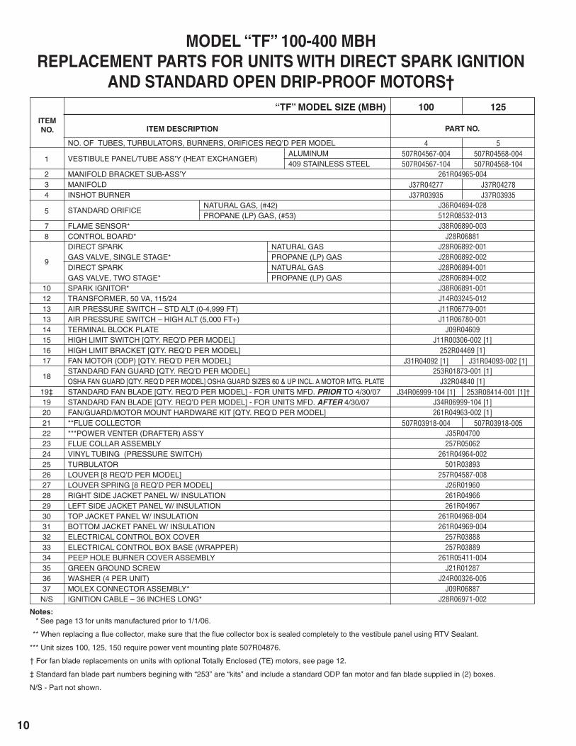
30-7530-7530-75
30 & 6045 & 7530-7530-7530-7530-7530-7530-75
PILOT BURNER ASSEMBLY NATURAL GAS
PROPANE (LP) GASPILOT MOUNTING BRACKET
PILOT TUBING
HONEYWELL SV9540 NATURAL GASGAS VALVE, SINGLE STAGE PROPANE (LP) GASFAN TIME DELAY SWITCHDRAFTOR RELAY*SMALL GROMMETWIRE HARNESS FOR SV9540 VALVE
MODELS WITH HOT SURFACE IGNITIONFor Units Manufactured Prior to January 1, 2006
J38R03421-001J38R03421-002
252R06603257R06605257R06604
J28R04979-001J28R04979-002
J11R00366J10R03410
J07R02872-004260R05001
MODEL “SF” 30-75 MBH – SEPARATED COMBUSTIONPART NO.ITEM DESCRIPTION
*A draftor relay is not required when unit is equipped with a Honeywell SV9540 Gas Valve (the relay function is built into the control).
SIZE/RANGE
30-9030-9030-90
30 & 6045, 75, 90
30-9030-9030-9030-9030-9030-9030-9030-9030-90
PILOT BURNER ASSEMBLY NATURAL GAS
PROPANE (LP) GASPILOT MOUNTING BRACKET
PILOT TUBING
HONEYWELL SV9500M† NATURAL GASGAS VALVE, SINGLE STAGE PROPANE (LP) GASHONEYWELL SV9540M NATURAL GASGAS VALVE, SINGLE STAGE PROPANE (LP) GASFAN TIME DELAY SWITCHDRAFTOR RELAY*WIRE HARNESS FOR SV9540 VALVE (RF UNITS)WIRE HARNESS FOR SV9540 VALVE (TF UNITS)WIRE HARNESS FOR SV9500 VALVE “CONTROL” (TF UNITS)
MODELS “TF/RF” 30-90 MBH – LOW PROFILEPART NO.ITEM DESCRIPTION
*A draftor relay is not required when unit is equipped with a Honeywell SV9540 or SV9640 Gas Valve (the relay function is built into the control).
†Replacement Valve is a Honeywell SV9501 Series.
SIZE/RANGE
NATURAL GAS
PILOT BURNER ASSEMBLY “C2” PROPANE (LP) GAS
NATURAL GAS (WHITE-RODGERS VALVE)*PILOT MOUNTING BRACKET
PILOT TUBING LENGTH = 24"
LENGTH = 28"
HONEYWELL SV(9500/9600)
NATURAL GAS
GAS VALVE, SINGLE STAGE PROPANE (LP) GAS
HONEYWELL SV(9540/9640)
NATURAL GAS
GAS VALVE, SINGLE STAGE PROPANE (LP) GAS 1/2" x 3/4" 3/4" x 3/4"WHITE-RODGERS GAS VALVE, SINGLE STAGE* NATURAL GASIGNITOR, NATURAL GASFAN TIME DELAY SWITCHDRAFTOR RELAY†WIRE HARNESS FOR SV9540 OR SV9640 VALVE “C1”WIRE HARNESS FOR SV9540 OR SV9460 VALVE “C3”WIRE HARNESS FOR SV9500 OR SV9600 VALVE “CONTROL”
J38R03421-001J38R03421-002
J38R04578-001
252R03892261R04962-003261R04962-004J28R05042-001
J28R05043-003**J28R05042-002***J28R05043-002**J28R05043-004J28R04979-001J28RO4980-003J28R04979-002J28R04980-002J28R04980-004
J28R00742J28R02722J11R00366J10R03410260R05002260R05361
260R04629-001
MODEL “TF” 100-400 MBHPART NO.ITEM DESCRIPTION SIZE/RANGE
*For units manufactured prior to June 13, 2001 (sizes 350 and 400 only).
**Replacement Valve is SV9601 Series.
***Replacement Valve is SV9501 Series.
†A draftor relay is not required when unit is equipped with a Honeywell SV9540 or SV9640 Gas Valve (the relay function is built into the control).

14
NOTES
15
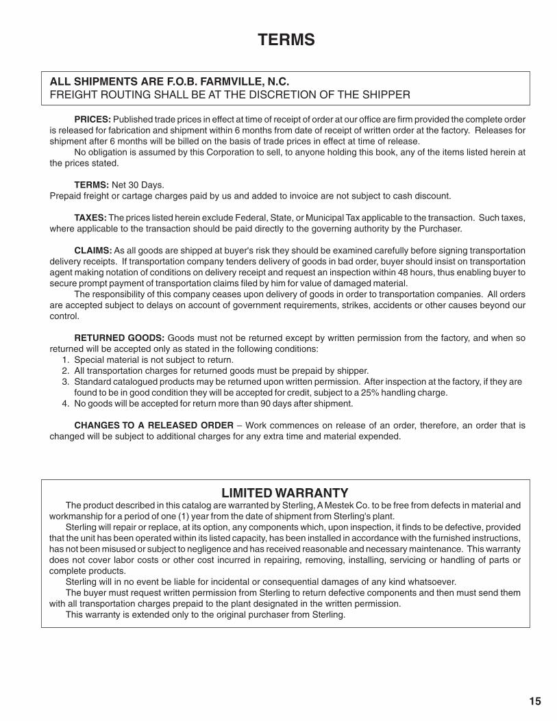
TERMS
LIMITED WARRANTYThe product described in this catalog are warranted by Sterling, A Mestek Co. to be free from defects in material and
workmanship for a period of one (1) year from the date of shipment from Sterling's plant.Sterling will repair or replace, at its option, any components which, upon inspection, it fi nds to be defective, provided
that the unit has been operated within its listed capacity, has been installed in accordance with the furnished instructions, has not been misused or subject to negligence and has received reasonable and necessary maintenance. This warranty does not cover labor costs or other cost incurred in repairing, removing, installing, servicing or handling of parts or complete products.
Sterling will in no event be liable for incidental or consequential damages of any kind whatsoever.The buyer must request written permission from Sterling to return defective components and then must send them
with all transportation charges prepaid to the plant designated in the written permission.This warranty is extended only to the original purchaser from Sterling.
ALL SHIPMENTS ARE F.O.B. FARMVILLE, N.C.FREIGHT ROUTING SHALL BE AT THE DISCRETION OF THE SHIPPER
PRICES: Published trade prices in effect at time of receipt of order at our offi ce are fi rm provided the complete order is released for fabrication and shipment within 6 months from date of receipt of written order at the factory. Releases for shipment after 6 months will be billed on the basis of trade prices in effect at time of release.
No obligation is assumed by this Corporation to sell, to anyone holding this book, any of the items listed herein at the prices stated.
TERMS: Net 30 Days. Prepaid freight or cartage charges paid by us and added to invoice are not subject to cash discount.
TAXES: The prices listed herein exclude Federal, State, or Municipal Tax applicable to the transaction. Such taxes, where applicable to the transaction should be paid directly to the governing authority by the Purchaser.
CLAIMS: As all goods are shipped at buyer's risk they should be examined carefully before signing transportation delivery receipts. If transportation company tenders delivery of goods in bad order, buyer should insist on transportation agent making notation of conditions on delivery receipt and request an inspection within 48 hours, thus enabling buyer to secure prompt payment of transportation claims fi led by him for value of damaged material.
The responsibility of this company ceases upon delivery of goods in order to transportation companies. All orders are accepted subject to delays on account of government requirements, strikes, accidents or other causes beyond our control.
RETURNED GOODS: Goods must not be returned except by written permission from the factory, and when so returned will be accepted only as stated in the following conditions:
1. Special material is not subject to return.2. All transportation charges for returned goods must be prepaid by shipper.3. Standard catalogued products may be returned upon written permission. After inspection at the factory, if they are found to be in good condition they will be accepted for credit, subject to a 25% handling charge.4. No goods will be accepted for return more than 90 days after shipment.
CHANGES TO A RELEASED ORDER – Work commences on release of an order, therefore, an order that is changed will be subject to additional charges for any extra time and material expended.

260 NORTH ELM ST. WESTFIELD, MA 01085 (413) 564-5540 • FAX: (413) 562-5311
www.sterlinghvac.com
HVAC PRODUCTS


![ENGINEERED PRODUCTS AND INDOOR MAKE-UP AIRmesteksa.com/fileuploads/Literature/Sterling Gas Products... · 2008-12-23 · 1, 2 - Unit Type [UT] 10 - Gas Control [GC] ... ENGINEERED](https://img.pdfslide.net/doc/110x75/5e75f69fc40661708610f6c4/engineered-products-and-indoor-make-up-gas-products-2008-12-23-1-2-unit.jpg)