Embed Size (px)
Citation preview

Installation and Operation Manual
Important:This manual contains specifi c cautionary statements relative to worker safety. Read this manual thoroughly and follow as directed. It is impossible to list all the hazards of dust control equipment. All persons involved with the equipment or
systems should be instructed how to operate in a safe manner.
MODEL TM1000

MODEL TM1000 SPECIFICATIONSINPUT VOLTAGE:120V 60Hz 1 Phase208-230V / 460V 60Hz 3 Phase
MAX. CURRENT:17 Amps (at 120V, 1 1/2HP, Single Phase)5.2 Amps (at 208-230V, 1 1/2HP, Three Phase)2.6 Amps (at 460V, 1 1/2HP, Three Phase)
MOTOR:TEFC 1 1/2 HP, 1 PhaseTEFC 1 1/2 HP, 3 Phase
COMPRESSED AIR: 2.0 SCF at 90 psi. maximum. 1/4” NPT male nipple connection.
DUST TRAY CAPACITY:528 cubic inches
EXTERNAL ARM:7 ft. or 9 ft. long, 6” or 8” diameter steel tube with 350 degree movement and two joints.
DIMENSIONS: 44-1/2” h. X 25-1/2” w. X 32-1/2” l.
SHIPPING WEIGHT: 350 lbs.
ACTUAL WEIGHT: 300 lbs.
PACKAGE CONTENTS:1 Ea. TM1000 OPTIONS (These items are separately packed): 1 ea. 6” or 8” dia., 7’ or 9’ Arm Assembly 1 ea. 4” dia. Dual Arm Assembly 1 ea. Down Draft Table 1 ea. Back Draft Hood 1 ea. Magnetic Hood Assembly with 15’ or 25’ Hose
Caution: All electrical work must be done by a qualifi ed electrician according to local, state and national codes.
PRE-OPERATING INSTRUCTIONS:NOTE: The following instructions will vary depending on
options received.1. Remove the shipping crate, shipping straps and plastic
wrapping from the unit.2. Remove the TM1000 from the shipping skid and set on
a level surface.3. Remove the attachment option from the shipping
carton.4. Install the arm assembly onto the base unit (Fig. 1).
5. Insert the lamp plug on the arm into the receptacle located directly behind the base of the arm on the TM1000 (Lamp only option).
OPERATING INSTRUCTIONS:1. Choose a suitable, level place near the workstation and
position the unit so that the hose/arm assembly will be placed near the source of pollution being generated. The TM1000 has locking wheels at the front handle end. The wheels are locked by stepping down on the fl at plate on the wheels.
2. Grasp the hood by the handle ring and position within 18” of the source of pollution.
3. Plug the power cord into a outlet of the appropriate voltage and phase.
MICRO AIR® TM1000 CLEAN AIR SYSTEMS
!
2
Fig. 1

4. Turn the power switch on (located near the Mini-Helic gauge).
5. The light control switch (optional) is mounted on the hood. Turn the light on as needed.
6. Adjust the hood to capture the maximum amount of contaminants. Periodically adjust the position of the hood to keep it in maximum capture range.
7. If the unit fan is rotating incorrectly (three phase only), switch L1 and L2 connections to reverse the rotation direction.
MINI-HELIC GAUGE OPERATION:1. As the cartridge fi lters collect airborne pollutants
they will eventually begin to become loaded with particulate. The fi lter loading will cause an increase in static pressure and a decrease in air fl ow.
2. The Mini-Helic gauge on the control panel indicates static pressure. Note the reading at the initial start-up. As the unit is operated the static pressure will gradually increase as the fi lters become loaded. This will indicate the need to back fl ush the system.
CARTRIDGE CLEANING:NOTE: Pulse clean cartridge fi lters frequently for proper operations. Failure to do so will decrease performance and lead to pre-mature fi lter failure. 1. The TM1000 is designed with a Roto-Pulse system to
clean the cartridge fi lters.2. Attach a shop air hose to the inlet located on the front
of the TM1000. It is recommended that a pressure regulator and water trap be installed between the shop air and the TM1000,
NOTE: Do not exceed 90 psi of shop air. Exceeding 90psi will result in fi lter damage.
3. Shut off the TM1000 blower.4. Push the cartridge back-fl ush control button (mounted
on the control panel) three or more times. This operation initiates the Roto-Pulse system which spins the tube inside the cartridge fi lter. As the tube spins, air dislodges the dirty particles from the cartridge fi lters. Theses particles then settle into the two removable dust trays.
5. After several cleaning cycles, the dust particles that have been collected by the TM1000 will need to be emptied from the dust trays. The frequency of dust removal depends on the type and quantity of pollutant that is collected. The dust trays should be emptied before the particles have accumulated to a depth of 1/2 inch.
6. To remove the dust trays from the TM1000, turn the unit off. Open the cartridge access door and slide out
the dust trays.7. Dump the dust out of the trays.8. Slide dust trays back into the TM1000. Close and latch
the fi lter access door.
CHANGING FILTERS:Caution: Always make sure that the unit is turned off before changing fi lters or servicing the unit.
1. Turn the TM1000 off and open the fi lter access door.2. Remove the cartridge fi lters retained by wing nuts.3. Slide new cartridge fi lters into the cabinet and retain
with wing nuts.4. Close the fi lter access door.
GENERAL MAINTENANCE:1. Check the wiring for loose connections for cracked
insulation.4. No lubrication is required for the motor because it is a
permanent pre-lube design.5. Once per month grease the suction arm base assembly
with a bearing grease listed to not react with aluminum.
TM1000 MICRO AIR® CLEAN AIR SYSTEMS
3
!

4
MICRO AIR® TM1000 CLEAN AIR SYSTEMS
Fig. 2
OPTIONAL HEPA / CHARCOAL FILTER INSTALLATION:KIT CONTENTS:1. 1 Ea. Left Filter Track 2. 1 Ea. Right Filter Track3. 1 Ea. Stretch Cord4. 6 Ea. #8 x 1/2” SMS5. 1 Ea. HEPA Filter or RCM Module
INSTALLATION:1. Remove the four (4) screws used to attach the lower panel and remove lower panel from the TM1000.2. Remove the exhaust restrictor plate3. Locate fi lter tracks shown in Fig. 2. Filter tracks are to be located fl ush to front edge of cabinet bottom and centered
above the exhaust opening (align fi lter track over pre-punched holes).4. Secure fi lter tracks to the TM1000 using six (6) each #8 x 1/2” sheet metal screws provided.5. To install fi lter, slide the fi lter in between tracks so that the airfl ow arrow points downward.6. Retain the fi lter with stretch cord provided.7. Replace the lower panel.
Caution: Exhaust restrictor plate is used in lieu of after fi lters to prevent motor overload. If the after fi lter is removed, re-install the restrictor plate prior to operating the unit. Failure to do so may result in damage to the motor or electrical circuit.
!
#8 x 32 SMS
Filter Track (Right)
RCM or HEPA
Lower Panel
Filter Track (Left)
Stretch Cord
Locate Filter Enclosure Flush With Edge Of Cabinet Bottom

5
TM1000 MICRO AIR® CLEAN AIR SYSTEMS
Fig. 3
Filter Track
OPTIONAL BIG WHEEL INSTALLATION:KIT CONTENTS:1 Ea. Big Wheel Assembly8 Ea. 5/16-18 x 1” Hex Bolt
INSTALLATION:1. Position the unit on its’ side with the bottom exposed.2. Remove the four (4) bolts, fl at washers and lock washers retaining each fi xed wheel. Retain the hardware for use in
step four.3. Place the Big Wheel Assembly onto the unit. Align the eight slotted holes over the holes in the unit, making sure that
the Big Wheel Assembly presses against the back wall of the unit.4. Install the lock washer, fl at washer and the 1” long hex bolts supplied with the kit. Secure the Big Wheel assembly to
the unit with the eight (8) 1” long hex bolts. Make sure the bolts are tight.5. Position the unit onto the wheels and reattach any attachments removed for installation.
Caution: Source capture arms or other attachments must no be attached during kit installation.!
Lock WasherFlat Wahser
Big Wheel KitExploded View
5/16-18 x 1” Hex Bolt

MICRO AIR® TM1000 CLEAN AIR SYSTEMS
6
Fig. 4
Backdraft Hood
OPTIONAL BACKDRAFT HOOD INSTALLATION:KIT CONTENTS:1 Ea. Backdraft Hood1 Ea. Flexible Hose1 Ea. Adapter Collar2 Ea. Hose Clamps
INSTALLATION:1. Lift and slide the Backdraft Hood into the upper receiving bracket (Fig. 4).2. Connect the Adapter collar to the top of the TM1000 with the 1/4-20 hardware provided.3. Place one end of the 8” diameter fl ex hose over the Backdraft Hood collar .4. Place the other end of the 8” diameter fl ex hose over the Adapter collar.5. Secure both ends of the 8” diameter fl ex hose with the supplied hose clamps.
NOTE: 15’ and 25’ hose lengths are available to allow the Backdraft Hood to be remote located.
Receiving Bracket
TM1000
Adapter CollarLocation

TM1000 MICRO AIR® CLEAN AIR SYSTEMS
7
Fig. 5
OPTIONAL DOWNDRAFT TABLE INSTALLATION:KIT CONTENTS:1 Ea. Downdraft Table1 Ea. Flexible Hose1 Ea. Adapter Collar2 Ea. Hose Clamps
INSTALLATION:1. Lift and slide the Downdraft Table into the lower receiving bracket (Fig. 5).2. Connect the Adapter collar to the top of the TM1000 with the 1/4-20 hardware provided.3. Place one end of the 8” diameter fl ex hose over the Downdraft Table collar .4. Place the other end of the 8” diameter fl ex hose over the Adapter collar.5. Secure both ends of the 8” diameter fl ex hose with the supplied hose clamps.
NOTE: 15’ and 25’ hose lengths are available to allow the Backdraft Hood to be remote located.
Caution: Force placed upon Downdraft Table must not exceed 50 lbs. when attached to the TM1000. Do not exceed 300 lbs. when remote mounted.!
Downdraft Table
Receiving Bracket
TM1000
Adapter CollarLocation

MICRO AIR® TM1000 CLEAN AIR SYSTEMS
8
TM1000 WIRING DIAGRAMS
Fig. 6A
Fig. 6B

TM1000 MICRO AIR® CLEAN AIR SYSTEMS
9
ITEM PART NO. DESCRIPTION1. 37107-01 Lamp Plate2. P2170 Lamp3. P2168 Lamp Socket4. P2466 6” Hood Assembly P2469 8” Hood Assembly5. 37106-01 Switch Box6. P2219 Rocker Switch7. P164 1/4-20 x 3/4” Hex Head Bolt8. P246 1/4 Flat Washer9. P2482 Hood Disc Pad10. P2485 1/4-20 Nylock Hex Nut11. 37104-01 Damper Handle Stop Plate12. P2206 5/16” Flat Washer13. P2484 5/16” Nylock Hex Nut14. 37103-01 Damper Handle15. P2478 1/2-13 x 2.25” Hex Head Bolt
ITEM PART NO. DESCRIPTION16. P2468 Cup Washer17. P2467 Friction Pad18. P2479 1/2-13 Nylock Hex Nut19. P141 3/8-16 Hex Nut20. P142 3/8” Lock Washer21. P2206 Flat Washer22. P2481 3/8-16 x 1.25” Carriage Bolt23. P2461 6” Gas Shock P2462 8” Gas Shock24. P2483 1/4-20 x 1” Hex Head Bolt25. P2312 Micro Air Decal26. P2232 Hose Clamp27. P2616 6” Dia. Flex Hose P2617 8” Dia. Flex HoseN/S P2471 4 Conductor Cable - 9’ longN/S P2472 4 Conductor Cable - 15’ long
6” & 8” DIAMETER ARM ASSEMBLY PARTS LIST
Fig. 7

MICRO AIR® TM1000 CLEAN AIR SYSTEMS
10
4” DIAMETER ARM ASSEMBLY PARTS LIST
ITEM PART NO. DESCRIPTION1. 37107-01 Lamp Plate2. P2170 Lamp3. P2168 Lamp Socket4. P2463 4” Hood Assembly5. 37106-01 Switch Box6. P2219 Rocker Switch7. P2483 1/4-20 x 1” Hex Head Bolt8. P246 1/4 Flat Washer9. P2482 Hood Disc Pad10. P2485 1/4-20 Nylock Hex Nut11. P2490 1/4-20 x 1” Carriage Bolt
ITEM PART NO. DESCRIPTION12. P2484 5/16” Nylock Hex Nut13. P2465 Cup Washer14. P2464 Friction Pad15. P2614 5/16-18 x 1” Hex Head Bolt16. P164 1/4-20 x 3/4” Hex Head Bolt17. P2460 4” Gas Shock18. P2470 4” Dia. Flex Hose19. P2232 Hose Clamp20. P2312 Micro Air DecalN/S P2471 4 Conductor Cable - 9’ longN/S P2472 4 Conductor Cable - 15’ long
Fig. 8
TM1000 MICRO AIR® CLEAN AIR SYSTEMS
11
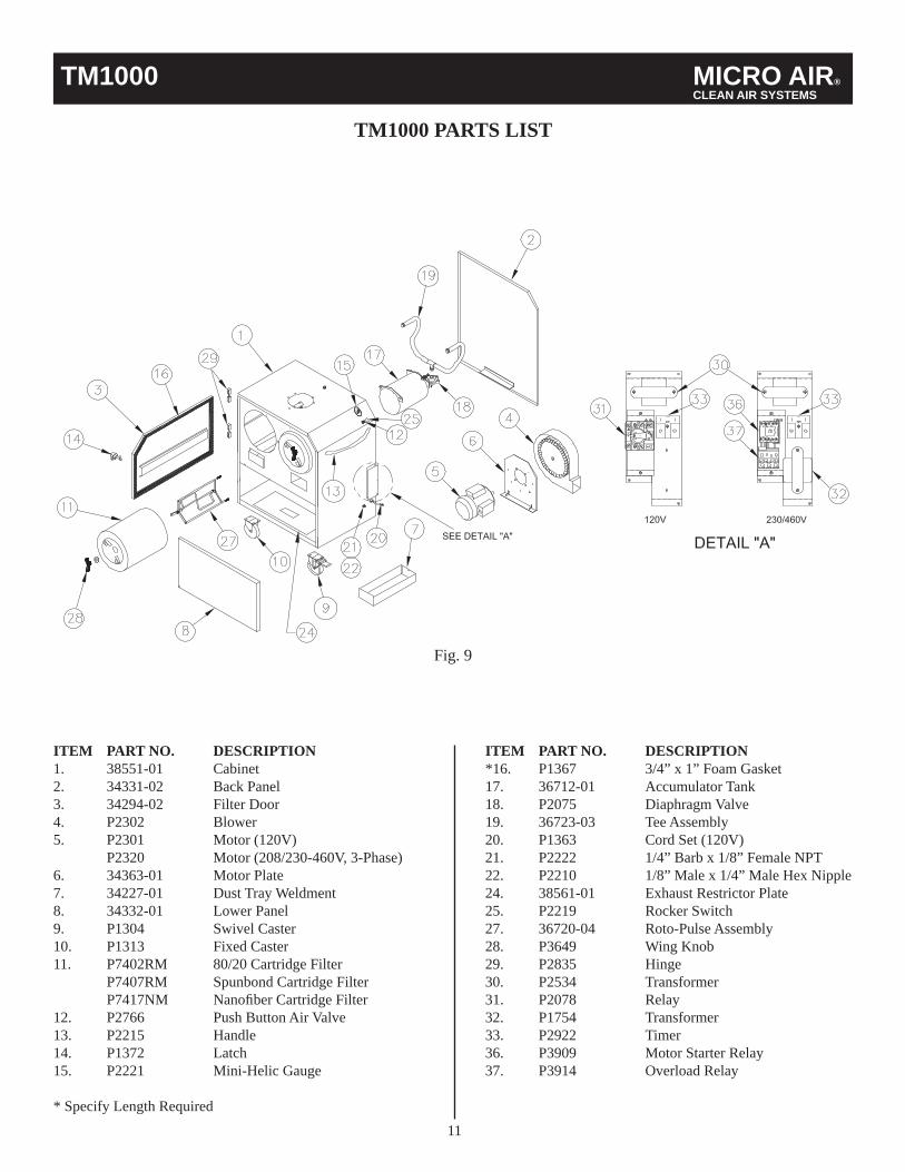
TM1000 PARTS LIST
ITEM PART NO. DESCRIPTION1. 38551-01 Cabinet2. 34331-02 Back Panel3. 34294-02 Filter Door4. P2302 Blower5. P2301 Motor (120V) P2320 Motor (208/230-460V, 3-Phase)6. 34363-01 Motor Plate7. 34227-01 Dust Tray Weldment8. 34332-01 Lower Panel9. P1304 Swivel Caster10. P1313 Fixed Caster11. P7402RM 80/20 Cartridge Filter P7407RM Spunbond Cartridge Filter P7417NM Nanofi ber Cartridge Filter12. P2766 Push Button Air Valve13. P2215 Handle 14. P1372 Latch15. P2221 Mini-Helic Gauge
* Specify Length Required
ITEM PART NO. DESCRIPTION*16. P1367 3/4” x 1” Foam Gasket17. 36712-01 Accumulator Tank18. P2075 Diaphragm Valve19. 36723-03 Tee Assembly20. P1363 Cord Set (120V)21. P2222 1/4” Barb x 1/8” Female NPT22. P2210 1/8” Male x 1/4” Male Hex Nipple24. 38561-01 Exhaust Restrictor Plate25. P2219 Rocker Switch27. 36720-04 Roto-Pulse Assembly28. P3649 Wing Knob29. P2835 Hinge30. P2534 Transformer31. P2078 Relay32. P1754 Transformer33. P2922 Timer36. P3909 Motor Starter Relay37. P3914 Overload Relay
Fig. 9

MICRO AIR® TM1000 CLEAN AIR SYSTEMS
TM1000 ACCESSORIES PARTS LIST
Fig. 10
Fig. 11
Fig. 12
DOWNDRAFT TABLEITEM PART NO. DESCRIPTION1. 38570-01 Downdraft Assembly2. 38576-01 Cleanout Drawer3. 38579-01 Shield Assembly4. P2314 Steel Grate5. P3506 Wing Nut6. P2319 Hose (Qty. 6 ft.)7. P2232 Hose Clamp8. 37123-02 Adapter Plate
BACKDRAFT TABLEITEM PART NO. DESCRIPTION1. 38499-01 Backdraft Assembly2. P2319 Hose (Qty. 5 ft.)3. P2232 Hose Clamp4. 37123-02 Adapter Plate
MAGNETIC HOODITEM PART NO. DESCRIPTION1. 38569-01 Hood Assembly2. P2303 Magnet3. P2232 Hose Clamp4. P2319 Hose (Qty. 15 ft. or 25 ft.)5. 37123-02 Adapter Plate6. P1342 Edge Guard
12

13
TROUBLE SHOOTING CHARTCAUTION: BEFORE DISASSEMBLING THE UNIT OR DOING ANY INSPECTING OF THE PARTS, MAKE CERTAIN THAT THE POWER HAS BEEN CUT OFF AND THE BLOWER HAS COME TO A COMPLETE STOP. NEVER RUN THE UNIT WITH THE ACCESS DOOR OPEN OR REMOVED.PROBLEM POSSIBLE CAUSE REMEDYUnit fails to start No incoming power
Blown breaker or fuse
Primary voltage to motor contactor is below 10% tolerance
Burned out motor
Tripped overload (3 Phase)
Thermal trip (120V)
Check line voltage
Replace fuse or throw breaker
Take steps to increase voltage to primary
Replace motor
Reset overload protector
Reset thermal tripUnit runs slowly or inadequate capture velocity
Wired for wrong voltage or improper rotation
Dirty fi lters
Internal obstruction
Check input voltageCheck wiring diagramSwitch L1 & L2 (3-phase only)
Service / Replace fi lters
Check if damper is openCheck inlet for blockageCheck hoses for proper connectionCheck hoses for holes
Vibration Loose mounting bolts
Foreign objects in blower
Dirty disposable fi lters
Tighten bolts
Remove debris from blower
Service or replace fi ltersUnit runs for a short period of time and stops
Exhaust restrictor plate removed
Incorrect extension cord size (120V)
Re-install Restrictor plate
Plug directly into outletUse a cord rated to 20 Amps
Stronger resistance during rotation of the arm
Lack of grease in the rotating socket Grease the rotating socket
Arm will not stay where it is placed
The joints are loose Tighten the joints
TM1000 MICRO AIR® CLEAN AIR SYSTEMS

L192007/13
14
Serial Number:
Supply Voltage:
Date Installed:
Installed By:
Notes:
MICRO AIR® TM1000 CLEAN AIR SYSTEMS


![S13419 Impressa Z6 chromium JC 120V/60Hz [UL2]juracapressoparts.com/user/JURA/Z-Line/Jura_Z6_13419_Parts_and... · 13419 Impressa Z6 chromium JC 120V/60Hz [UL2] go Individual parts](https://img.pdfslide.net/doc/110x75/5c154a8e09d3f2340f8d1adf/s13419-impressa-z6-chromium-jc-120v60hz-ul2-13419-impressa-z6-chromium-jc.jpg)


![S13187 Impressa E8 black JC 120V/60Hz [UL2]juracapressoparts.com/user/Jura_Impressa_E8_120V... · S13187 Impressa E8 black JC 120V/60Hz Pos Designation 0401 Incoming feeder USA sw](https://img.pdfslide.net/doc/110x75/5cdae77288c993ff288baae1/s13187-impressa-e8-black-jc-120v60hz-ul2-s13187-impressa-e8-black-jc-120v60hz.jpg)