Embed Size (px)
Citation preview

Model UT511OPERATING MANUAL
TITLE PAGE
Model UT511: OPERATING MANUAL
1
IntroductionUnpacking the MeterSafety InformationInternational Electrical SymbolsBattery Saver (Sleep Mode)Battery IndicationThe Meter StructureDisplayKey FunctionsMeasurement Operation A.Measuring Voltages B.Measuring Insulation Resistance a) Continuous Measurement b) Timed Measurement c) Polarization Index (PI) Measurement d) Compare Function C. Low Resistance Measurement
555788910121515161718181920
2
21222222242424252526262627
Model UT511: OPERATING MANUAL
TITLE PAGE
The Use of Power AdaptorMaintenance A. General Service B. Replacing the BatterySpecificationsSafety and CompliancesPhysical SpecificationsGeneral SpecificationsFeature SummaryDetailed Accuracy Specifications A. Voltage Measurement B. Insulation Resistance Measurement C. Low Resistance Measurement

3
Model UT511: OPERATING MANUAL
Table Title Page
1. Unpacking Inspection2. International Electrical Symbols3. Battery Indication4. Meter Front Description5. Meter Side Description6. Display Description7. Key Description
5789101112
4
Model UT511: OPERATING MANUAL
Figure Title Page
1. The Meter Front Structure2. The Meter Side Structure3. The Display4. Voltage Measurement5. Insulation Resistance Measurement6. Low Resistance Measurement7. The Use of Power Adaptor8. Battery Replacement
910101516202123
5
Model UT511: OPERATING MANUAL
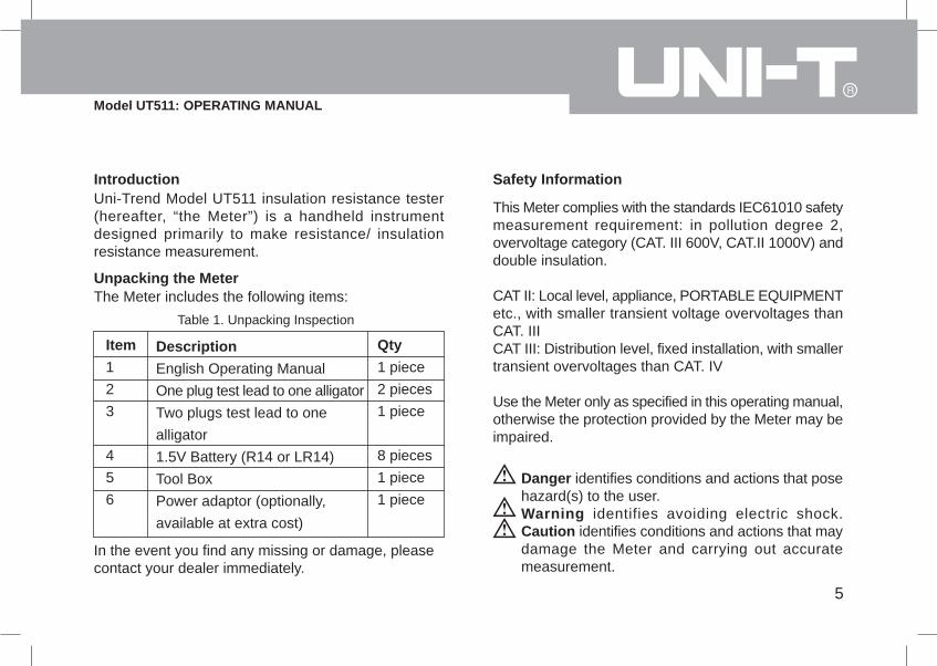
IntroductionUni-Trend Model UT511 insulation resistance tester(hereafter, “the Meter”) is a handheld instrumentdesigned primarily to make resistance/ insulationresistance measurement.
Unpacking the MeterThe Meter includes the following items:
Table 1. Unpacking Inspection
Item123
456
DescriptionEnglish Operating ManualOne plug test lead to one alligatorTwo plugs test lead to onealligator1.5V Battery (R14 or LR14)Tool BoxPower adaptor (optionally,available at extra cost)
Qty1 piece2 pieces1 piece
8 pieces1 piece1 piece
In the event you find any missing or damage, pleasecontact your dealer immediately.
Safety Information
This Meter complies with the standards IEC61010 safetymeasurement requirement: in pollution degree 2,overvoltage category (CAT. III 600V, CAT.II 1000V) anddouble insulation.
CAT II: Local level, appliance, PORTABLE EQUIPMENTetc., with smaller transient voltage overvoltages thanCAT. IIICAT III: Distribution level, fixed installation, with smallertransient overvoltages than CAT. IV
Use the Meter only as specified in this operating manual,otherwise the protection provided by the Meter may beimpaired.
Danger identifies conditions and actions that posehazard(s) to the user.Warning identifies avoiding electric shock.Caution identifies conditions and actions that maydamage the Meter and carrying out accuratemeasurement.
ll
ll
l
l
6
Model UT511: OPERATING MANUAL
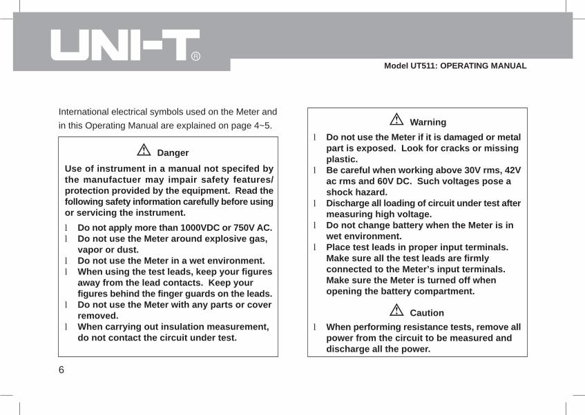
International electrical symbols used on the Meter andin this Operating Manual are explained on page 4~5.
Danger
Use of instrument in a manual not specifed bythe manufactuer may impair safety features/protection provided by the equipment. Read thefollowing safety information carefully before usingor servicing the instrument.
Do not apply more than 1000VDC or 750V AC.Do not use the Meter around explosive gas,vapor or dust.Do not use the Meter in a wet environment.When using the test leads, keep your figuresaway from the lead contacts. Keep yourfigures behind the finger guards on the leads.Do not use the Meter with any parts or coverremoved.When carrying out insulation measurement,do not contact the circuit under test.
Warning
l
l
l
l
l
Do not use the Meter if it is damaged or metalpart is exposed. Look for cracks or missingplastic.Be careful when working above 30V rms, 42Vac rms and 60V DC. Such voltages pose ashock hazard.Discharge all loading of circuit under test aftermeasuring high voltage.Do not change battery when the Meter is inwet environment.Place test leads in proper input terminals.Make sure all the test leads are firmlyconnected to the Meter’s input terminals.Make sure the Meter is turned off whenopening the battery compartment.
Cautionl When performing resistance tests, remove all
power from the circuit to be measured anddischarge all the power.
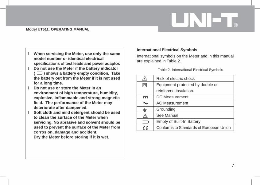
Risk of electric shockEquipment protected by double orreinforced insulation.DC MeasurementAC MeasurementGroundingSee ManualEmpty of Built-In BatteryConforms to Standards of European Union
7
Model UT511: OPERATING MANUAL
l
l
l
l
When servicing the Meter, use only the samemodel number or identical electricalspecifications of test leads and power adaptor.Do not use the Meter if the battery indicator( ) shows a battery empty condition. Takethe battery out from the Meter if it is not usedfor a long time.Do not use or store the Meter in anenvironment of high temperature, humidity,explosive, inflammable and strong magneticfield. The performance of the Meter maydeteriorate after dampened.Soft cloth and mild detergent should be usedto clean the surface of the Meter whenservicing. No abrasive and solvent should beused to prevent the surface of the Meter fromcorrosion, damage and accident.Dry the Meter before storing if it is wet.
International Electrical SymbolsInternational symbols on the Meter and in this manualare explained in Table 2.
Table 2. International Electrical Symbols
8
Model UT511: OPERATING MANUAL
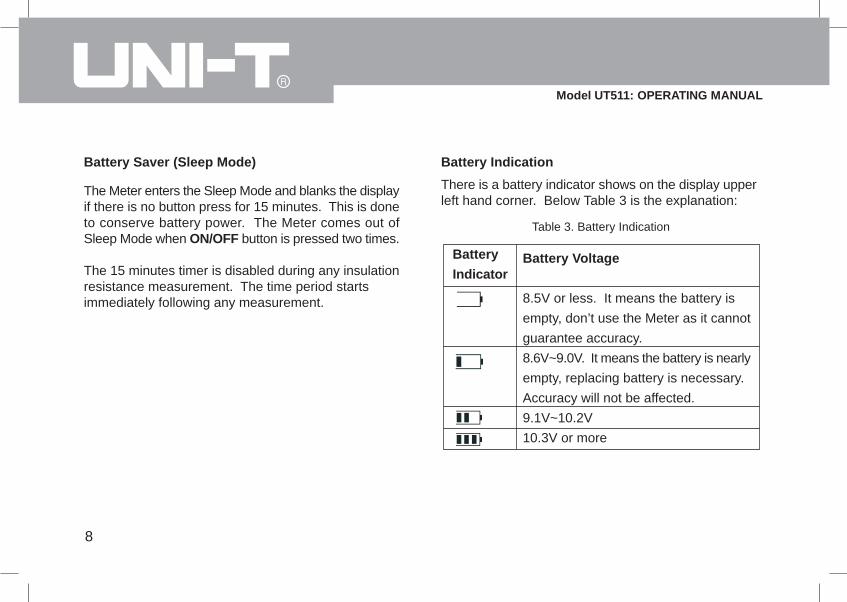
Battery Saver (Sleep Mode)
The Meter enters the Sleep Mode and blanks the displayif there is no button press for 15 minutes. This is doneto conserve battery power. The Meter comes out ofSleep Mode when ON/OFF button is pressed two times.
The 15 minutes timer is disabled during any insulationresistance measurement. The time period startsimmediately following any measurement.
Battery Indication
There is a battery indicator shows on the display upperleft hand corner. Below Table 3 is the explanation:
Battery Voltage
8.5V or less. It means the battery isempty, don’t use the Meter as it cannotguarantee accuracy.8.6V~9.0V. It means the battery is nearlyempty, replacing battery is necessary.Accuracy will not be affected.9.1V~10.2V10.3V or more
Table 3. Battery Indication
BatteryIndicator
9
Model UT511: OPERATING MANUAL
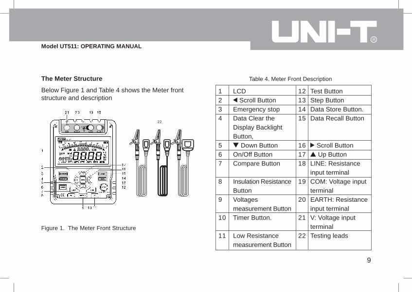
The Meter Structure
Below Figure 1 and Table 4 shows the Meter frontstructure and description
Figure 1. The Meter Front Structure
1234
567
8
9
10
11
Table 4. Meter Front Description
LCD Scroll Button
Emergency stopData Clear theDisplay BacklightButton,
Down ButtonOn/Off ButtonCompare Button
Insulation ResistanceButtonVoltagesmeasurement ButtonTimer Button.
Low Resistancemeasurement Button
12131415
161718
19
20
21
22
Test ButtonStep ButtonData Store Button.Data Recall Button
Scroll Button Up Button
LINE: Resistanceinput terminalCOM: Voltage inputterminalEARTH: Resistanceinput terminalV: Voltage inputterminalTesting leads
10
Model UT511: OPERATING MANUAL
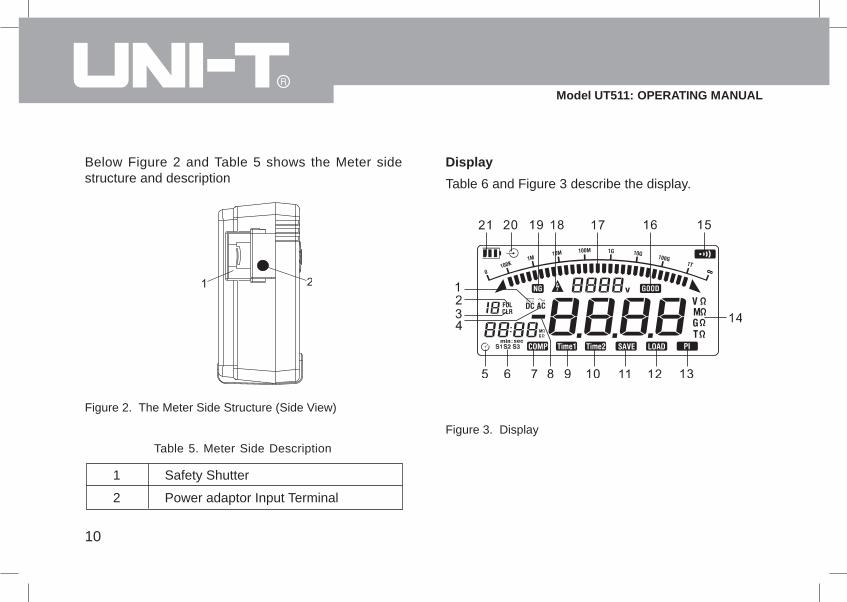
Below Figure 2 and Table 5 shows the Meter sidestructure and description
Figure 2. The Meter Side Structure (Side View)
Table 5. Meter Side Description
1 Safety Shutter
2 Power adaptor Input Terminal
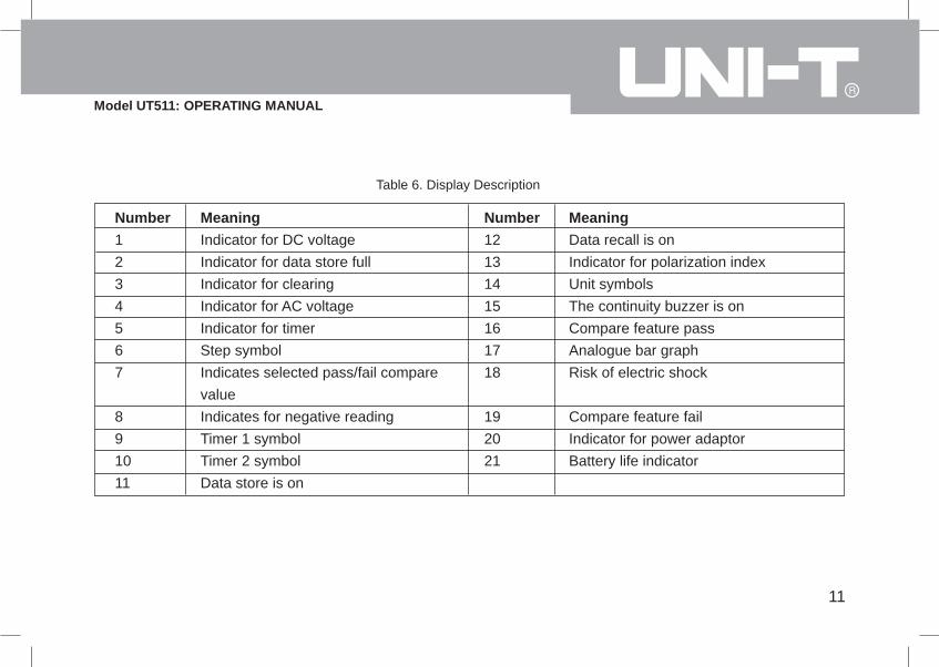
Display
Table 6 and Figure 3 describe the display.
Figure 3. Display
11
Model UT511: OPERATING MANUAL
Table 6. Display Description
Number1234567
891011
MeaningIndicator for DC voltageIndicator for data store fullIndicator for clearingIndicator for AC voltageIndicator for timerStep symbolIndicates selected pass/fail comparevalueIndicates for negative readingTimer 1 symbolTimer 2 symbolData store is on
Number12131415161718
192021
MeaningData recall is onIndicator for polarization indexUnit symbolsThe continuity buzzer is onCompare feature passAnalogue bar graphRisk of electric shock
Compare feature failIndicator for power adaptorBattery life indicator

12
Model UT511: OPERATING MANUAL
Key FunctionsTable 7. Key Description
ON/OFF
CLEAR/
SAVE
LOAD
Turn on or off the Meter. Press and holdthe button for 1 second to turn the Meteron.Press to clear the stored data,Push 1SEC to turn on and off the displaybacklight.Press to store the current measurementvalue. The maximum number of storedreading is 18. When the stored readingsmemory is full, the Meter shows FULLand stop storing. Press CLEAR to clearthe stored value in order to store thenext measurement value.l Press once to recall the first stored value.l Press again to exit Load feature.l Load feature can only be used when there is no high voltage output.
l Under insulation resistance measurement mode: press to select one voltage range up.l Under load mode: press to recall the previous stored value.l Under insulation resistance measurement mode: press to select one voltage range down.l Under load mode: press to recall the next stored value.l When set the timer duration for the measurement of insulation resistance or polarization index, press to decrement the time. The maximum length of time is 30 minutes, the Meter will automatically carry out measurement.
13
Model UT511: OPERATING MANUAL
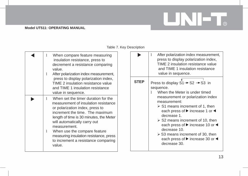
Table 7. Key Description
l When compare feature measuring insulation resistance, press to decrement a resistance comparing value.l After polarization index measurement, press to display polarization index, TIME 2 insulation resistance value and TIME 1 insulation resistance value in sequence.l When set the timer duration for the measurement of insulation resistance or polarization index, press to increment the time. The maximum length of time is 30 minutes, the Meter will automatically carry out measurement.l When use the compare feature measuring insulation resistance, press to increment a resistance comparing value.
l After polarization index measurement, press to display polarization index, TIME 2 insulation resistance value and TIME 1 insulation resistance value in sequence.
Press to display S1 S2 S3 insequence.l When the Meter is under timed measurement or polarization index measurement: S1 means increment of 1, then each press of increase 1 or decrease 1. S2 means increment of 10, then each press of increase 10 or decrease 10. S3 means increment of 30, then each press of increase 30 or decrease 30.
STEP

14
Model UT511: OPERATING MANUAL
l When the Meter is under compare mode: S1 means increment of 1, then each press of increase 1 or decrease 1. S2 means increment of 10, then each press of increase 10 or decrease 10. S3 means increment of 100, then each press of increase 100 or decrease 100.
STEP
Set a pass / fail limit for insulation tests.The default value is 100MPres to step through continuousmeasurement, timed measurement andpolarization index measurement insequence.Press to stop or start an insulationresistance testPress to initiate insulation resistancemeasurement
COMP
TIME
TEST
Ho
Table 7. Key Description
Press to initiate low resistancemeasurementPres to initiate voltages measurement
Lo
DVC/ACV
Emergency stop button. Press thisbutton when the Meter is hang andcannot turn off the power.
E-STOP
15
Model UT511: OPERATING MANUAL
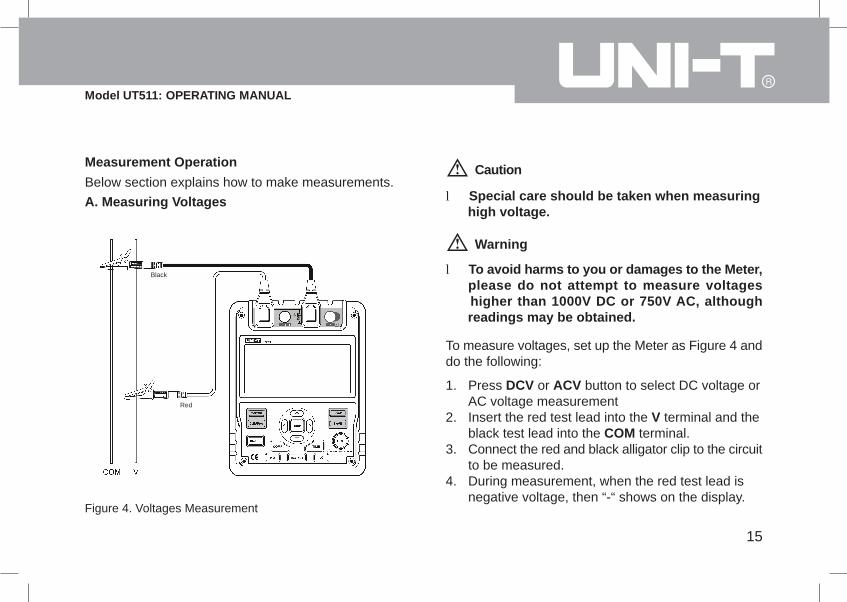
Measurement OperationBelow section explains how to make measurements.A. Measuring Voltages
Figure 4. Voltages Measurement
l Special care should be taken when measuring high voltage.
Caution
Warning
l To avoid harms to you or damages to the Meter, please do not attempt to measure voltages higher than 1000V DC or 750V AC, although readings may be obtained.
To measure voltages, set up the Meter as Figure 4 anddo the following:
Press DCV or ACV button to select DC voltage orAC voltage measurementInsert the red test lead into the V terminal and theblack test lead into the COM terminal.Connect the red and black alligator clip to the circuitto be measured.During measurement, when the red test lead isnegative voltage, then “-“ shows on the display.
1.
2.
3.
4.
Black
Red
16
Model UT511: OPERATING MANUAL
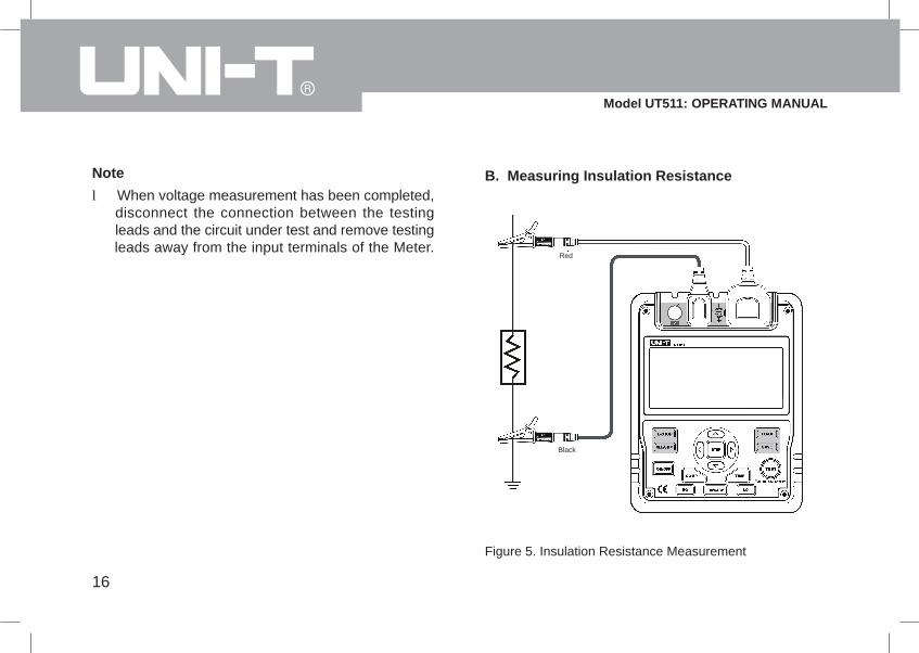
l When voltage measurement has been completed, disconnect the connection between the testing leads and the circuit under test and remove testing leads away from the input terminals of the Meter.
Note B. Measuring Insulation Resistance
Figure 5. Insulation Resistance Measurement
Red
Black
l
l
l
l
l
l
17
Model UT511: OPERATING MANUAL
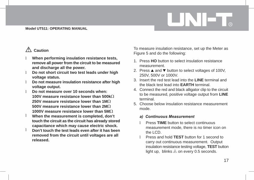
When performing insulation resistance tests,remove all power from the circuit to be measuredand discharge all the power.Do not short circuit two test leads under highvoltage status.Do not measure insulation resistance after highvoltage output.Do not measure over 10 seconds when:100V measure resistance lower than 500k250V measure resistance lower than 1M500V measure resistance lower than 2M1000V measure resistance lower than 5MWhen the measurement is completed, don’ttouch the circuit as the circuit has already storedcapacitance which may cause electric shock.Don’t touch the test leads even after it has beenremoved from the circuit until voltages are allreleased.
Caution To measure insulation resistance, set up the Meter asFigure 5 and do the following:
1.
2.
3.
4.
5.
Press HO button to select insulation resistancemeasurement.Press and button to select voltages of 100V,250V, 500V or 1000V.Insert the red test lead into the LINE terminal andthe black test lead into EARTH terminal.Connect the red and black alligator clip to the circuitto be measured, positive voltage output from LINEterminal.Choose below insulation resistance measurementmode.
l
l
Press TIME button to select continuousmeasurement mode, there is no timer icon onthe LCD.Press and hold TEST button for 1 second tocarry out continuous measurement. Outputinsulation resistance testing voltage, TEST buttonlight up, blinks on every 0.5 seconds.
18
Model UT511: OPERATING MANUAL
Press TEST button to close the insulation resistancemeasurement voltage when measurement iscompleted. TEST button lights off , disappears. The LCD shows the current insulation resistancemeasurement value.
Press TIME button to select timed measurementmode, the LCD displays TIME 1 and symbols.Press , and STEP buttons to set the time(00:05~29:30).Then press and hold TEST button for 1 second tocarry out timed measurement. TIME 1 and aredisplayed and blinked on the LCD on every 0.5seconds.When the set time is reached, the insulationresistance measurement voltage will be closed andthe measurement will be automatically stopped.The LCD displays the insulation resistance reading.
l
l
l
l
Press TIME button to select timed measurementmode, the LCD displays TIME 1 and symbols.Press , and STEP buttons to set the time(00:05~29:30).Press TIME button again. TIME 2, PI and symbolsappear on the LCD.Press , and STEP buttons to set the time(00:10~30:00).Then press and hold TEST button for 1 second tocarry out timed measurement.TIME 1 and are displayed and blinked on theLCD on every 0.5 seconds before TIME 1 set timeis reached.TIME 2 and are displayed and blinked on theLCD on every 0.5 seconds before TIME 2 set timeis reached.When the two set time are reached, the insulationresistance measurement voltage will be closed andthe measurement will be automatically stopped.The LCD displays the polarization index reading.
l
l
l
l
l
l
l
l
19
Model UT511: OPERATING MANUAL
Press , to set through the polarization index,TIME 2 insulation resistance reading and TIME 2insulation resistance reading.
l
Information:PI = 3 minutes ~10 minutes reading / 30 second ~1minutes reading
PIStandard
4 or moreThe best
4~2Good
2.0~1.0Warning
1.0 or lessBad
Press COMP button to select compare feature.COMP symbol displays on the LCD.Press , and STEP buttons to set the comparevalue. The minimum value is 1M The maximumvalue is the maximum tested voltage allowablemeasurement value.Press and hold TEST button for 1 second to carryout the measurement.The NG symbol will display if the insulation resistancevalue is smaller than resistance value. OtherwiseGOOD symbol will be displayed.
l
l
l
l
20
Model UT511: OPERATING MANUAL
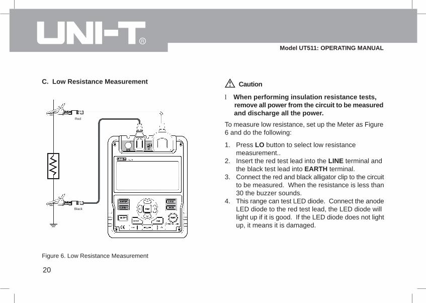
C. Low Resistance Measurement
Figure 6. Low Resistance Measurement
Caution
l When performing insulation resistance tests, remove all power from the circuit to be measured and discharge all the power.
To measure low resistance, set up the Meter as Figure6 and do the following:
Press LO button to select low resistancemeasurement..Insert the red test lead into the LINE terminal andthe black test lead into EARTH terminal.Connect the red and black alligator clip to the circuitto be measured. When the resistance is less than30 the buzzer sounds.This range can test LED diode. Connect the anodeLED diode to the red test lead, the LED diode willlight up if it is good. If the LED diode does not lightup, it means it is damaged.
1.
2.
3.
4.
Red
Black

21
Model UT511: OPERATING MANUAL
The Use of Power AdaptorThe use of power adaptor, see figure 7
Open the side safey shutter, then you will see thereis a power adaptor input terminal.Make sure the Meter is power off and Insert theUT511 power adaptor to the input terminal.It is highly recommed to take out all the batterieswhen you are using the power adaptor.Make sure the Meter is power off when youdisconnect the UT511 power adaptor from the Meter.(Input voltage 230VAC, Frequency 50/60Hz, Inputcurrent 50mA, Output voltage DC 15V, MAX current600mA)
1.
2.
3.
4.
Figure 7. The Use of Power Adaptor
Caution
If you want to choose power adaptor for power supply,please use special power adaptor SA48-150060EUwhich supported by our company, otherwise it will bedangerous.

22
Model UT511: OPERATING MANUAL
MaintenanceThis section provides basic maintenance informationincluding battery replacement instruction.
Do not attempt to repair or service your Meter unlessyou are qualified to do so and have the relevantcalibration, performance test, and serviceinformation.
Warning
A. General ServicePeriodically wipe the case with a damp cloth andmild detergent. Do not use abrasives or solvents.To clean the terminals with cotton bar with detergent,as dirt or moisture in the terminals can affect readings.Turn the Meter to OFF when it is not in use.Take out the battery when it is not using for a longtime.Do not use or store the Meter in a place of humidity,high temperature, explosive, inflammable and strongmagnetic field.If the Meter is wet, dry it before use.
l
l
ll
l
l
B. Replacing the Battery
Warning
To avoid electric shock, remove all the test leadsfrom the Meter when replacing the batteries.
Caution
Don’t mix to use old and new batteries.Be careful the polarity is correct when installingbatteries.Do not use the Meter if the battery indicator( ) shows a battery empty condition.
ll
l
23
Model UT511: OPERATING MANUAL
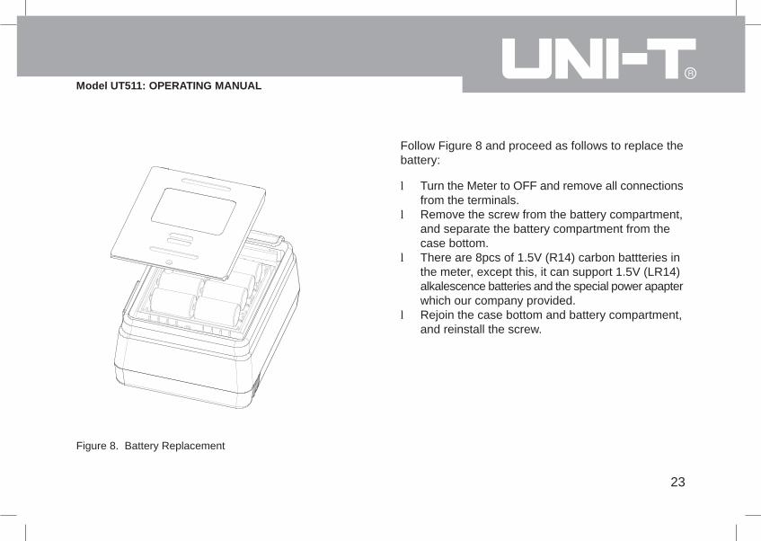
Figure 8. Battery Replacement
Follow Figure 8 and proceed as follows to replace thebattery:
Turn the Meter to OFF and remove all connectionsfrom the terminals.Remove the screw from the battery compartment,and separate the battery compartment from thecase bottom.There are 8pcs of 1.5V (R14) carbon battteries inthe meter, except this, it can support 1.5V (LR14)alkalescence batteries and the special power apapterwhich our company provided.Rejoin the case bottom and battery compartment,and reinstall the screw.
l
l
l
l
24
Model UT511: OPERATING MANUAL
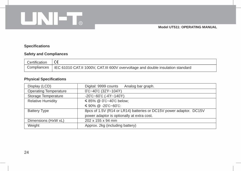
Specifications
Safety and Compliances
CertificationCompliances IEC 61010 CAT.II 1000V, CAT.III 600V overvoltage and double insulation standard
Physical Specifications
Display (LCD)Operating TemperatureStorage TemperatureRelative Humidity
Battery Type
Dimensions (HxW xL)Weight
Digital: 9999 counts Analog bar graph.0 ~40 (32 ~104 )-20 ~60 (-4 ~140 )
85% @ 0 ~40 below; 90% @ -20 ~60 :
8pcs of 1.5V (R14 or LR14) batteries or DC15V power adaptor. DC15Vpower adaptor is optionally at extra cost.202 x 155 x 94 mmApprox. 2kg (including battery)
25
Model UT511: OPERATING MANUAL
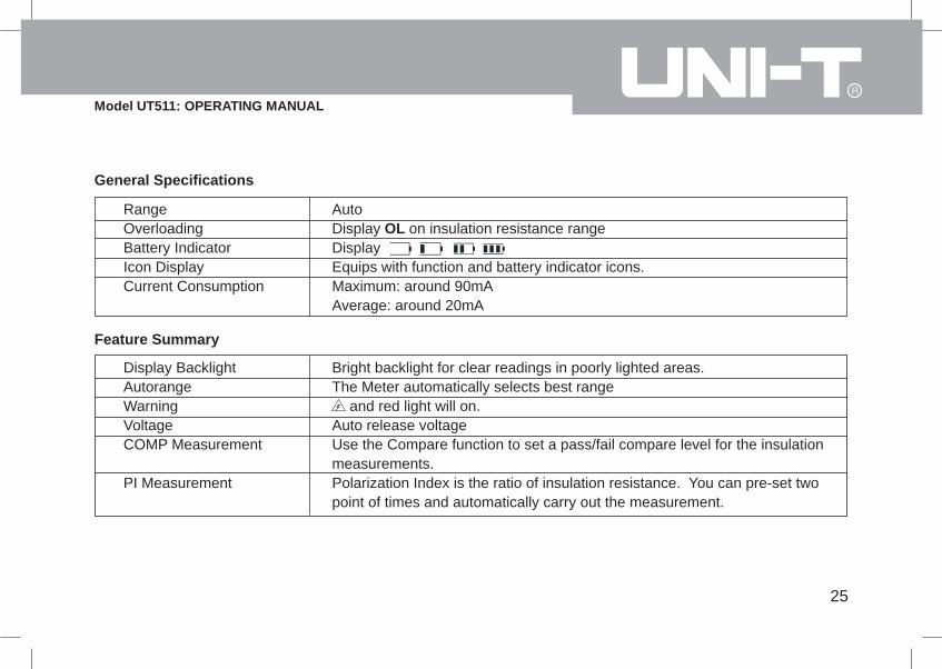
General Specifications
RangeOverloadingBattery IndicatorIcon DisplayCurrent Consumption
AutoDisplay OL on insulation resistance rangeDisplayEquips with function and battery indicator icons.Maximum: around 90mAAverage: around 20mA
Feature Summary
Display BacklightAutorangeWarningVoltageCOMP Measurement
PI Measurement
Bright backlight for clear readings in poorly lighted areas.The Meter automatically selects best range
and red light will on.Auto release voltageUse the Compare function to set a pass/fail compare level for the insulationmeasurements.Polarization Index is the ratio of insulation resistance. You can pre-set twopoint of times and automatically carry out the measurement.
26
Model UT511: OPERATING MANUAL
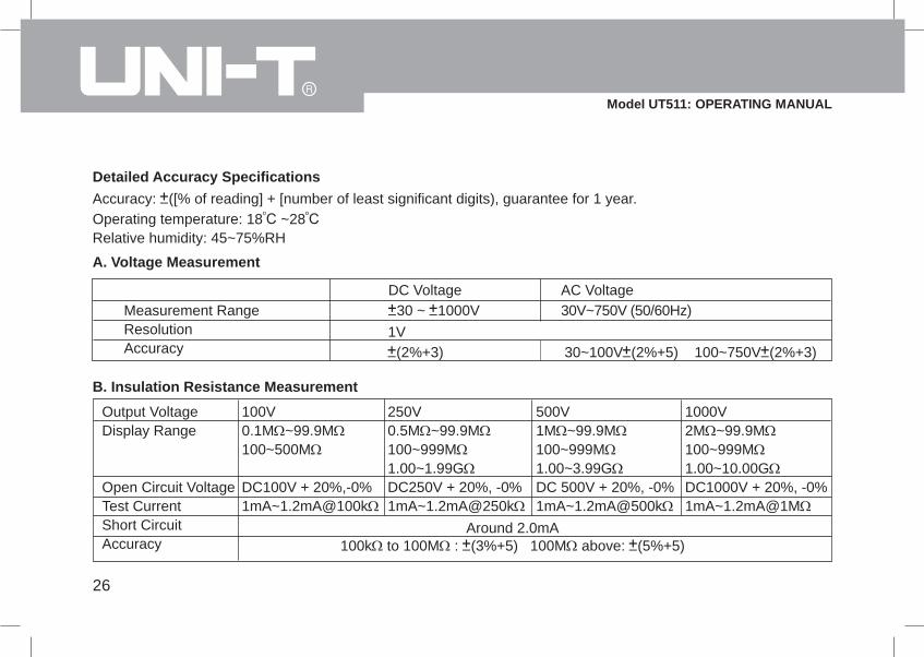
Detailed Accuracy SpecificationsAccuracy: ([% of reading] + [number of least significant digits), guarantee for 1 year.Operating temperature: 18 ~28Relative humidity: 45~75%RH
A. Voltage Measurement
Measurement RangeResolutionAccuracy
DC Voltage30 ~ 1000V
AC Voltage30V~750V (50/60Hz)
1V(2%+3) 30~100V (2%+5) 100~750V (2%+3)
B. Insulation Resistance Measurement
Output VoltageDisplay Range
Open Circuit VoltageTest CurrentShort CircuitAccuracy
100V0.1M ~99.9M100~500M
DC100V + 20%,-0%1mA~1.2mA@100k
250V0.5M ~99.9M100~999M1.00~1.99GDC250V + 20%, -0%1mA~1.2mA@250k
500V1M ~99.9M100~999M1.00~3.99GDC 500V + 20%, -0%1mA~1.2mA@500k
1000V2M ~99.9M100~999M1.00~10.00GDC1000V + 20%, -0%1mA~1.2mA@1M
Around 2.0mA100k to 100M : (3%+5) 100M above: (5%+5)

27
Model UT511: OPERATING MANUAL
At any output voltage, when the tested resistance is les than 5MΩ, the testing time cannot exceed 10 seconds.Caution
C. Low Resistance Measurement
FunctionMeasurement RangeResolutionAccuracyMaximum open circuit voltageBuzzerOverload Protection
Resistance0.1Ω~999.9Ω0.1Ω
(1%+3)Around 2.8VOpen at less than 30Ω220V rms/10 seconds
28
Model UT511: OPERATING MANUAL
This operating manual is subject to change without notice.
*END*

29
Model UT511: OPERATING MANUAL
Copyright 2006 Uni-Trend Group Limited.All rights reserved.
Manufacturer:Uni-Trend Technology (Dongguan) LimitedDong Fang Da DaoBei Shan Dong Fang Industrial Development DistrictHu Men Town, Dongguan CityGuang Dong ProvinceChinaPostal Code: 523 925
Headquarters:Uni-Trend Group LimitedRm901, 9/F, Nanyang Plaza57 Hung To RoadKwun TongKowloon, Hong KongTel: (852) 2950 9168Fax: (852) 2950 9303Email: [email protected]://www.uni-trend.com