Embed Size (px)
Citation preview

serial number -
MODEL VX10.2XLPROR TILE SAWOwner’s/OperatOr’s Manual
Caution! Read Safety and General Instructions carefully before using saw for the first time.
You should record the Serial Number of your Tile Saw on thisOwner’s/Operator’s Manual and on the Warranty Card. The WarrantyCard must be sent back with all the required pertinent informationfor the warranty to take effect.
Covered by one or more of the following US Patents:6,080,041; 6,119,676; 6,272,990; 6,460,533; and D458,282
Pear
l Ab
rasi
ve C
o.2.
1TI
LE S
AW
REV. 2
R
RENTAL

TABLE OF CONTENTS
i. general safety rules fOr all pOwer tOOls . . . . . . . . . . . . . . . . . . . . . . . . . . . . . . . 3
ii. syMbOls . . . . . . . . . . . . . . . . . . . . . . . . . . . . . . . . . . . . . . . . . . . . . . . . . . . . . . . . . . . . . . . . . . . 4
iii. features . . . . . . . . . . . . . . . . . . . . . . . . . . . . . . . . . . . . . . . . . . . . . . . . . . . . . . . . . . . . . . . . . . . 5
iv. specificatiOns . . . . . . . . . . . . . . . . . . . . . . . . . . . . . . . . . . . . . . . . . . . . . . . . . . . . . . . . . . . . . 5
v. getting tO KnOw yOur saw. . . . . . . . . . . . . . . . . . . . . . . . . . . . . . . . . . . . . . . . . . . . . . 6
vi. blade installatiOn . . . . . . . . . . . . . . . . . . . . . . . . . . . . . . . . . . . . . . . . . . . . . . . . . . . . . . . 7
vii. safe Operating practices fOr tile saw. . . . . . . . . . . . . . . . . . . . . . . . . . . . . . . . . . . . 7
viii. grOunding instructiOns. . . . . . . . . . . . . . . . . . . . . . . . . . . . . . . . . . . . . . . . . . . . . . . . . 9
iX. using the cutting table . . . . . . . . . . . . . . . . . . . . . . . . . . . . . . . . . . . . . . . . . . . . . . . . . 10
X. care and Maintenance . . . . . . . . . . . . . . . . . . . . . . . . . . . . . . . . . . . . . . . . . . . . . . . . . . 11
Xi. bearing hOusing replaceMent . . . . . . . . . . . . . . . . . . . . . . . . . . . . . . . . . . . . . . . . . . . 13
Xii. cutting depth . . . . . . . . . . . . . . . . . . . . . . . . . . . . . . . . . . . . . . . . . . . . . . . . . . . . . . . . . . . 13
Xiii. belt replaceMent. . . . . . . . . . . . . . . . . . . . . . . . . . . . . . . . . . . . . . . . . . . . . . . . . . . . . . . . . 14
Xiv. replaceMent part lists . . . . . . . . . . . . . . . . . . . . . . . . . . . . . . . . . . . . . . . . . . . . . . . . . . . 14
Xv. accessOries and parts . . . . . . . . . . . . . . . . . . . . . . . . . . . . . . . . . . . . . . . . . . . . . . . . . . . 19
Xvi. the right blades dOes the right JOb. . . . . . . . . . . . . . . . . . . . . . . . . . . . . . . . . . . . . 20
Xvii. hOw tO Order parts. . . . . . . . . . . . . . . . . . . . . . . . . . . . . . . . . . . . . . . . . . . . . . . . . . . . . 20
Xviii. electrical MOtOr specificatiOn . . . . . . . . . . . . . . . . . . . . . . . . . . . . . . . . . . . . . . . . . 21
XiX. trOubleshOOting. . . . . . . . . . . . . . . . . . . . . . . . . . . . . . . . . . . . . . . . . . . . . . . . . . . . . . . . 22
page

– 3 –
i. GENERAL SAFETY RULES FOR ALL POWER TOOLS
1. Know your power tool - read owner’s/operator’s manual carefully. Learn its applications and limitations aswell as the specific potential hazards unique to this tool.
2. Keep guards in place - and in working order.
3. Ground all tools - if tools are equipped with three prong plug, it should be plugged into a three-hole electricalreceptacle. If an adapter is used to accommodate a two-prong receptacle, the adapter lug must be attachedto a known ground. Never remove the third prong.
4. Remove wrenches - Form a habit of checking to see that adjusting wrenches are removed from tool beforeturning it “on”.
5. Keep work area clean. Cluttered areas and benches invite accidents.
6. Do not use in dangerous environment. Do not use power tools in damp or wet locations, or expose them torain. Keep work area well lighted. Do not use tool in the presence of flammable liquids or gasses.
7. Keep children and visitors away. All children and visitors should be kept at a safe distance from work area.
8. Make workshop childproof with padlocks, master switches or by removing starter keys.
9. Do not force tool. It will do the job better and be safer at the rate for which it was designed.
10. Use right tool. Do not force tool or attachment to do a job for which it was not designed.
11. Wear proper apparel. Do not wear loose clothing, gloves, neckties, rings, bracelets or other jewelry that mayget caught in moving parts. Non-slip footwear is recommended. Wear protective hair covering to containlong hair.
12. Always use safety glasses. Wear safety glasses (must comply with ANSI Z87.1) at all times. Everydayeyeglasses only have impact resistant lenses; they are not safety glasses. Use face or dust mask if cuttingoperation is dusty, and ear protectors (plugs or muffs) during extended periods of operation.
13. Do not overreach. Keep proper footing and balance at all times.
14. Maintain tools in top condition. Keep tools sharp and clean for best and safest performance. Followinstructions for lubricating and changing accessories. Inspect tool cords periodically and if damaged, haverepaired by authorized service facility.
15. Disconnect tools. When not in use, before servicing, and when changing accessories, such as blades, bits,cutters.
16. Avoid accidental starting. Make sure switch is in “off” position before plugging in power cord.
17. Use recommended accessories only. Consult the owner’s manual for recommended accessories. The useof improper accessories may cause risk of injury to persons.
18. Never stand on tool. Serious injury could occur if the tool is tipped or if the cutting tool is accidentallycontacted.
19. Check Damaged Parts. Before further use of the tool, a guard or other part that is damaged should becarefully checked to ensure that it will operate properly and perform it’s intended function. Check foralignment of moving parts, binding of moving parts, breakage of parts, mounting, and any other conditionsthat may affect it’s operation. A guard or part that is damaged should be properly repaired or replaced.
20. Never leave tool running unattended. Turn power “off”. Do not leave tool until it comes to a complete stop.
Read all instructions. As with all machinery there are certain hazards involved withoperation and use of the machine. The following basic safety precautions should be followed at all times toreduce the risk of fire, electric shock and serious personal injury to you or others. Keep these importantoperating instructions with this product.
WARNING!
– 4 –
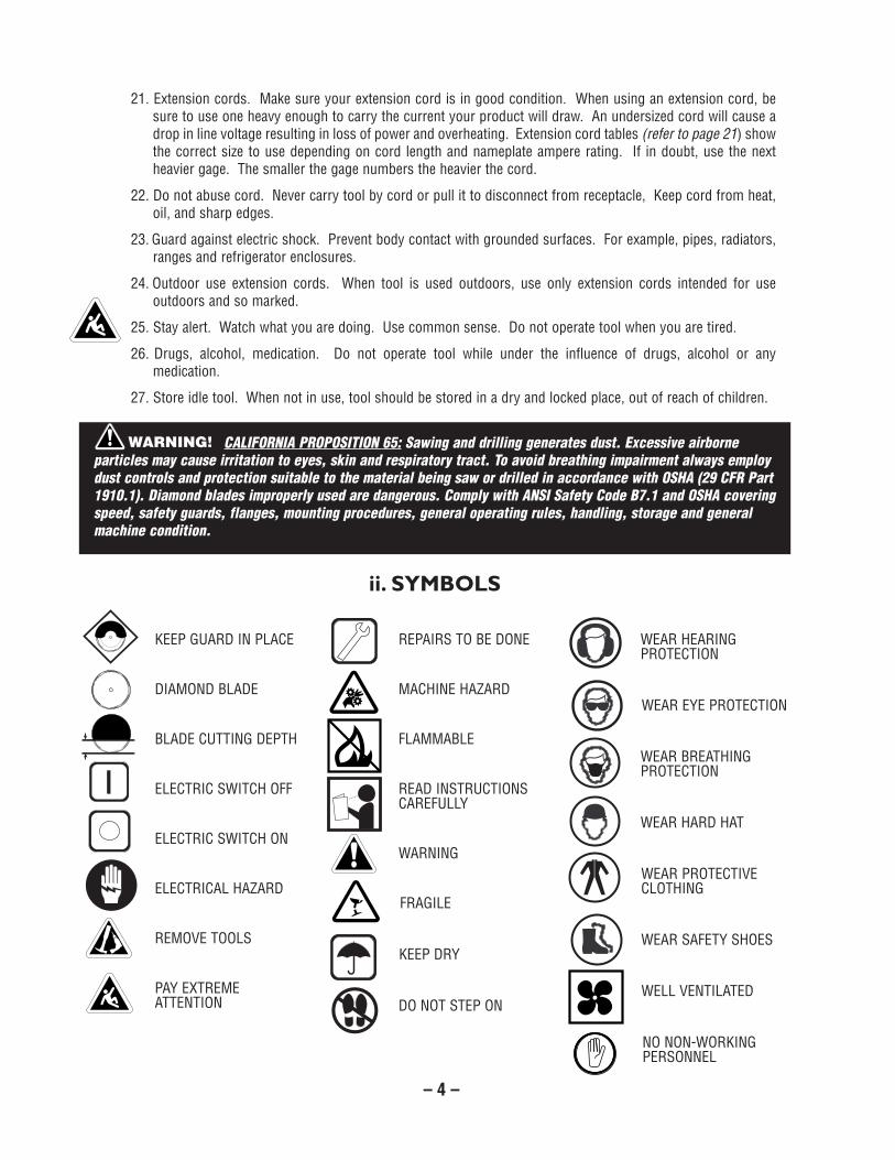
KEEP GUARD IN PLACE
DIAMOND BLADE
BLADE CUTTING DEPTH
ELECTRIC SWITCH OFF
ELECTRIC SWITCH ON
ELECTRICAL HAZARD
REMOVE TOOLS
PAY EXTREMEATTENTION
REPAIRS TO BE DONE
MACHINE HAZARD
FLAMMABLE
READ INSTRUCTIONSCAREFULLY
WARNING
FRAGILE
KEEP DRY
DO NOT STEP ON
WEAR HEARINGPROTECTION
WEAR EYE PROTECTION
WEAR BREATHINGPROTECTION
WEAR HARD HAT
WEAR PROTECTIVECLOTHING
WEAR SAFETY SHOES
WELL VENTILATED
NO NON-WORKINGPERSONNEL
21. Extension cords. Make sure your extension cord is in good condition. When using an extension cord, besure to use one heavy enough to carry the current your product will draw. An undersized cord will cause adrop in line voltage resulting in loss of power and overheating. Extension cord tables (refer to page 21) showthe correct size to use depending on cord length and nameplate ampere rating. If in doubt, use the nextheavier gage. The smaller the gage numbers the heavier the cord.
22. Do not abuse cord. Never carry tool by cord or pull it to disconnect from receptacle, Keep cord from heat,oil, and sharp edges.
23. Guard against electric shock. Prevent body contact with grounded surfaces. For example, pipes, radiators,ranges and refrigerator enclosures.
24. Outdoor use extension cords. When tool is used outdoors, use only extension cords intended for useoutdoors and so marked.
25. Stay alert. Watch what you are doing. Use common sense. Do not operate tool when you are tired.
26. Drugs, alcohol, medication. Do not operate tool while under the influence of drugs, alcohol or anymedication.
27. Store idle tool. When not in use, tool should be stored in a dry and locked place, out of reach of children.
ii. SYMBOLS
CALIFORNIA PROPOSITION 65: Sawing and drilling generates dust. Excessive airborneparticles may cause irritation to eyes, skin and respiratory tract. To avoid breathing impairment always employdust controls and protection suitable to the material being saw or drilled in accordance with OSHA (29 CFR Part1910.1). Diamond blades improperly used are dangerous. Comply with ANSI Safety Code B7.1 and OSHA coveringspeed, safety guards, flanges, mounting procedures, general operating rules, handling, storage and generalmachine condition.
WARNING!

– 5 –
iii. FEATURES
The Pearl VX10.2XLPROR is a portable professional tile saw. Lightweight and compact it has innovative built in featuresthat enable it to cut larger format tiles. The unique main table allow the saw to increase its cutting capacity whenneeded. The main table and extension carriage are supported by low friction, self cleaning, adjustable guide wheels.Water flow to the blade is provided by two (2) nozzles that directs the water to both sides of the blade. The ruggedpowder coated steel frame sets in a removable water tray for easy clean up.
• Powerful Motor - 2 hp.
• Heavy Duty ON/OFF switch.
• Automatic Thermal Overload protects your saw from power surges and motor overheating.
• Heavy Duty Stainless Steel Water Tray.
• Stainless Steel Rail guides.
• Adjustable Cutting Head allows user to align saw at any time.
• 10-Sealed Metal Roller bearings.
• Blade Capacity - 10".
• Diagonal Cut up to 18" tiles and rip cut up to 24" in length.
The heavy duty, cast to last, construction and quality components were designed to meet the highest demands of theprofessional.
Read this manual completely and then let the Pearl VX10.2XLPROR take your cutting capabilities to new dimensions.
VX10.2XLPROR TILE SAW
MOTORARBOR SHAFT
ROTATIONMAX. BLADE
CAPACITYWEIGHT DIMENSIONS
iv. SPECIFICATIONS
Counter-Clockwise
5/8" arbor blade,8, 9 & 10" Blade
84 lbs. Width: 21"Length: 24"
2 HP115 v, 60 Hz,Single phase

– 6 –
v. GETTING TO KNOW YOUR SAW
Roller Kit
Water Tray
Carriage Assembly
Main TableAssembly
MotorAssembly
Blade Guard
DiamondBlade
Blade GuardAdjustment
Knob
Vertical ArmAssembly
Lock Pin
Drip Tray
Blade Wrench
Power Switch
FRONT
45º/90º RipGuide

– 7 –
vi. BLADE INSTALLATION
1. Carefully raise the cutting head to its highestposition and secure it into place by tighteningthe cutting head adjustment knob in the rearsupport.
2. Raise the blade guard to the highest positionand tighten the blade guard adjustment knob.
3. Remove the blade shaft nut and outerflange.
4. Place the blade onto the shaft making sure thatthe directional arrows are pointing in thedirection of rotation.
5. After making sure that the blade is firmlyplaced against the inner flange, secure it intoplace with the outer flange and blade shaft nut.Make certain the nut if firmly tightened with thewrench provided, but do not over tighten!
7. Lower the blade guard and tighten theadjustment knob.
8. Slightly loosen the rear support adjustmentknob, lower the cutting head so that the bladeis 3/16" to 1/4" below the surface of the cuttingtable, and then tighten the adjustment knobfirmly to hold the cutting head in place.
WARNING: Setting the blade too low maydamage the cutting table and if set too high,the blade may grab the material being cut,causing damage and possibly injury.
vii. SAFE OPERATING PRACTICES FOR TILE SAW
1. Use safety equipment - wear safety approvedhearing, eye, head and respirator protection.
2. Read and understand the symbol definitionscontained in this manual.
3. Read and understand all warnings andinstructions on the machine.
4. Read all safety materials and instructions thataccompany any blade or accessory used withthis machine.
5. Establish a training program for all operationsof this machine.
6. Always provide a copy of this manual to theequipment user. If you need extra copies call our Customer Service Department at 1-800-969-5561.
7. Always select a diamond blade according tothe manufacturers recommendation suitablefor the material to be cut. Never use a bladehaving a maximum operating speed lower thanthe “No load R.P.M.” marked on the tool
The dust generated by cuttingof tile, marble, stone, bricks etc. can be injuriousto your health. Always operate machinery in wellventilated areas and provide proper dust removal.Always wear a dust mask approved for respiratoryprotection against these types of dusts and mists.
For your own safety and thesafety of others do not attempt to operate this sawuntil you have read and understand the generalsafety rules for all power tools and the followingadditional safety precaution unique to this saw.
WARNING!
WARNING!
Figure 1
– 8 –
nameplate. Do not operate any saw withoutsafety guards in place or with a blade diameterlarger than the maximum saw blade capacity.
8. Before mounting a blade on the saw clean andinspect the arbor shaft, blade flanges and thediamond blade for uneven wear or damage. Ifit appears to be damaged, Do not operate thetool. Have it serviced by a qualified servicetechnician.
9. Before each use of the saw, inspect thediamond blade for hairline fatigue cracks. Ifsuch a crack or flaw is evident, discard theblade. Using a damaged blade may causeinjury to the operator or others.
10. Be sure that the blade arbor hole matches theblade adapter flange supplied with the saw.Use only blade adapter flanges that came onyour saw. Never use damaged or worn bladeadapter flanges.
11. Installing the blade, install the blade with thearrow pointing the same direction as therotation of the arbor shaft or the arrow on theblade guard. Be sure to tighten the blade shaftarbor nut with the wrench provided.Be careful not to over tighten.
12. Check that the blade tracks near the center ofthe channel in the main table, and that the tablemoves freely from front to back.
13. Sometimes the material being cut is notabrasive enough to expose new diamonds onthe blade. If the blade is not sharpened, it willrub against the surface resulting in heat buildup in the core. To prevent this, it is necessaryto dress the blade. To dress the blade simplycut something that is very abrasive such as apiece of cement block. Indications that theblade needs dressing includes:
• The diamond in the matrix appear shinybecause they are worn flat.
• The blade stops cutting or noticeablyslows down.
Blade dressing stones are available from your local PearlWarehouse.
14. Before using the saw fill the water tub enoughto submerge the water pump with clean wateronly. Replenish as necessary and clean thewater tub frequently. Do not operate a wetcutting blade without adequate water flow toboth sides of the blade. Never run the pumpdry.
15. When cutting, always hold the material firmlylying flat, supported by the main table with oneedge resting against the main table backstop.
• Do not attempt to cut pieces too small tosafely hold down on the main table.
• Never use the side of the blade to cut orgrind with, only cut in a straight line.
• Keep all parts of your body away from theblade and all other moving parts.
• Never touch or try to stop a moving bladewith your hand.
16. When cutting dry - always unplug the waterpump first. Never run the pump dry.
• Do not use a wet cutting blade for drycutting. Select the proper dry cuttingblade for your application.
• Never make long continuous cuts with drycutting blades. To avoid heat build up,allow the blade to cool, remove the tileand allow the blade to run freely for a fewminutes.
IMPORTANT - If there is any tendency for thesaw to tip or move during certain operations,such as when cutting large heavy tile; the sawmust be securely fastened to a supportingtable.
17. Make certain all adjusting knobs or locks aretight and engaged in their detents and thatmovable parts not intended to move duringoperation are securely locked before making acut. Be careful not to over tighten.
18. Before connecting the machine to a powersource check to see that the “On/Off” switch isin the “off” position.
• Make sure the blade is not contactinganything before connecting to a powersource and starting the motor.
• Know how to stop the machine quickly incase of an emergency.
Not dressing the bladefrequently or setting the blade too high will causeit to grab the tile possibly causing injury to theoperator and the saw. Setting the blade depth toolow will cause it to cut into the main table thatmay result in injury.
WARNING!

– 9 –
1. Always use the included GFCI plug.
2. In the event of a malfunction or breakdown,grounding provides a path of least resistance forelectric current, reducing the risk of electricshock. This tool is equipped with an electric cordwhich has an equipment-grounding conductorand a grounding plug. The plug must be pluggedinto a matching outlet that is properly installedand grounded in accordance with all local codesand ordinances.
3. Do not modify the plug provided – it is intendedto be used with the included GFCI plug andextension cord. If using an adaptor for a 2-prongoutlet, always attach the adaptor to the GFCIplug, never to the power cord.
4. Improper connection of the equipment-grounding conductor can result in a risk ofelectric shock.
5. Check with a qualified electrician or serviceperson if you do not completely understand thegrounding instructions or are unsure that the toolis properly grounded.
6. If an additional extension cord is needed, attachit to the 3-prong GFCI plug. Never use anextension cord longer than 50 feet.
Always repair or replace a damaged or worn cordimmediately.
7. This saw is intended for use on a circuit that hasan outlet that looks like the one illustrated inFigure 2. The GFCI plug used on the saw has agrounding plug that looks like the plug illustratedin Figure 2(A). A temporary adaptor, which lookslike the adaptor illustrated in Figures 2(B) and2(C), may be used to connect the GFCI plug to a
2-pole receptacle, as shown in Figure 2(B), if aproperly grounded outlet is not available. Thetemporary adaptor should be used only until aproperly grounded outlet can be installed by aqualified electrician. The green-colored rigid ear,lug, etc., extending from the adaptor must beconnected to a permanent ground, such as aproperly grounded outlet box.
8. Position of the Tile Saw.
• To avoid the possibility of the appliance plugor receptacle getting wet, position the tilesaw to one side of a wall-mountedreceptacle to prevent water from drippingonto the receptacle or plug. The usershould arrange a “drip loop” in the cordconnecting the saw to a receptacle. The“drip loop” is that part of the cord below thelevel of the receptacle, or the connector (ifan extension cord is used); it preventswater from traveling along the cord andcoming into contact with the receptacle.See Figure 3.
• If the plug or receptacle does get wet, do notunplug the cord. Disconnect the fuse orcircuit breaker that supplies power to thereceptacle. Then unplug and examine forthe presence of water in the receptacle.
• If the receptacle is wet, dry it and makecertain that the GFCI Plug is reset beforeplugging it back into the receptacle. Do notreconnect the fuse or circuit breaker untilthe receptacle is dry.
NOTE - Use of a Temporary Adapter is not permittedin Canada.
Figure 2
(A) (B) (C)GFCIplug
Grounding pin
Cover ofgroundedoutlet box
MetalScrew
GroundingMeans(Lug)
Grounding pin
viii. GROUNDING INSTRUCTIONS

– 10 –
9. Extension Cords
• Always use the extension cord included withthe saw.
• If an additional extension cord is needed, useonly a cord that is intended for outdoor use.These extension cords are identified by themarking “Acceptable for use with outdoorappliances; store indoors while not in use.”Use only extension cords with an electricalrating higher than the rating of the tool. Referto the chart on page 14. Do not use damagedextension cords. Examine an extension cordbefore use and replace it if it is damaged. Donot abuse extension cords and do not pull onany cord to disconnect it. Keep the cord awayfrom heat and sharp edges. Alwaysdisconnect the extension cord from thereceptacle before disconnecting the saw fromthe extension cord.
• Never use an additional extension cord that islonger than 50 feet.
10. Always use the Ground Fault Circuit Interrupter(GFCI) plug included with the saw.
11. The tile saw cord includes a 15-amp twist lockplug. Do not modify this plug or use an adaptoron it. This plug is intended to be used with theGFCI Plug included with the saw. The GFCI hasa standard 3-prong plug that can be pluggedinto a standard 3-prong outlet or extensioncord.
Features:
• Cutting table marked in inches for precisioncuts.
• 14” cutting table provides more support duringlarger cutting jobs than the standard 11”cutting tables.
Using 90˚ Rip Guide:
1. Set the rip guide by positioning it on thedesired dimension and tighten the threadedknob. Make sure that the rip guide is firmlytightened to avoid slippage. The rip guide canbe used for 90˚ rip cuts from both the left andright side.
2. After the rip guide is positioned for the desiredcut, place material flat against the rip guide andthe table measurement rail.
3. Simply line-up the material being cut with theappropriate pre-marked lines on the cuttingtable surface.
4. Now you are ready to make your cut.
Making Miter Cuts (Using Optional Miter Block):
1. For miter cuts, place the lip of the miter blockon the measurement rail, with the threadedknobs facing you.
2. Tighten the threaded knobs to secure the miterblock in place.
3. Place material onto miter block and you areready to cut.
ix. USING THE CUTTING TABLE
Figure 4Cutting large tile
VX10.2XLPROR can cut a 24" tile anddiagonally cut a 18" tile.
To reduce the risk of electrocution, keepall connections dry and off the ground.Do not touch plug with wet hands.
TOOL
Figure 3Drip Loop
SupportingSurface
Power Cord
Drip LoopGFCI/Power CordConnection
GFCI plug

– 11 –
The Pearl VX10.2XLPROR requires very littlemaintenance however, keeping your saw clean andproperly adjusted will ensure optimum performance.Take great care not to get water into the motor. Do notuse pressure washer to clean motor area.
1. Cleaning
• Form a habit of cleaning your saw aftereach use. To clean the water tub, removedrain plug provided in bottom of tub.Remove saw including water pump fromtub. Remove residual water and clean tubusing soap and water only. Reinstall sawwith pump into tub.
• To increase water pump life remove tile gritby purging water. Pump with fresh waterafter each use.
• With a damp cloth or sponge wipe cleanthe guide rails and all other surfaces onthe saw where dust and debris hasaccumulated.
2. Transporting
• Unplug the power cord and store it in theempty, dry water tub. For convenienceand safety, the saw should be transportedwith both the main table and carriagelocked, motor in upper position and alladjustment knobs tightened.
3. Sliding Carriage Adjustment
• Make sure that all rails and rollers areclean.
• If carriage and/or table does not slidesmoothly, it will require tensionadjustment as follows:
A. Raise saw 2”-3” from table or workbench(front and rear) gaining acces to (red)pivot adjuster bolts. See Figure 5.
B. Locate (red) pivot adjuster on frame base.Adjust roller tension against extrusioncarriage by loosening socket head bolt
directly below adjuster. See Figure 5.
C. With bolt loose, turn (red) pivot adjuster
(3/4” wrench is needed) either counter-clockwise (putting the roller into theextrusion) or clockwise (pulling the rolleraway from the extrusion.)
D. Tighten lower hex-bolt when finished.
E. Since four rollers are adjustable on base,all may need attention at operator’sdiscretion. If the table is not running freelyor feels loose, sometimes it is difficult todiscern which one needs adjustment. Thesimplest procedure is to loosen ALL fouradjusters and re-adjust in sequentialorder:a. Right Side Middleb. Right Side Rearc. Right Side Frontd. Left Side Middle
Be sure to check for looseness or bindingafter each roller adjustment.
4. Table Roller Adjustment
A. Loosen (4) hex-screws on table top.
B. Adjust tension on rollers by turning setscrew (on outside of table) until desiredtension is achieved. DO NOT OVER-TIGHTEN. See Figure 6.
C. Re-tighten the (4) screws on table top.Check table movement and re-adjust ifnecessary. Table should roll free butwithout side movement.
NOTE - Do not lubricate the guide rails. The presenceof oil or grease will cause an accumulation of dustand dirt.
x. CARE AND MAINTENANCE
For your safety before performing any maintenance on the saw turn off the power switchand unplug the power cord.
WARNING!
Figure 5Sliding carriage adjustment
PivotAdjuster(red)
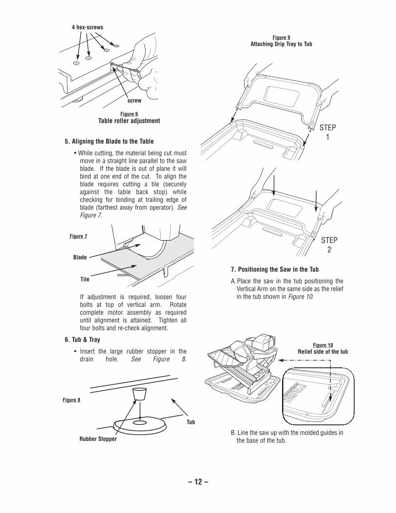
5. Aligning the Blade to the Table
• While cutting, the material being cut mustmove in a straight line parallel to the sawblade. If the blade is out of plane it willbind at one end of the cut. To align theblade requires cutting a tile (securelyagainst the table back stop) whilechecking for binding at trailing edge ofblade (farthest away from operator). SeeFigure 7.
If adjustment is required, loosen fourbolts at top of vertical arm. Rotatecomplete motor assembly as requireduntil alignment is attained. Tighten allfour bolts and re-check alignment.
6. Tub & Tray
• Insert the large rubber stopper in thedrain hole. See Figure 8.
7. Positioning the Saw in the Tub
A.Place the saw in the tub positioning theVertical Arm on the same side as the reliefin the tub shown in Figure 10.
B. Line the saw up with the molded guides inthe base of the tub.
Blade
Tile
Figure 7
Rubber Stopper
Tub
Figure 8
Figure 9Attaching Drip Tray to Tub
STEP1
STEP2
Figure 10Relief side of the tub
Figure 6Table roller adjustment
4 hex-screws
screw
– 12 –

– 13 –
8. Connecting the Water Pump
A. Attach the provided adapter to the waterpump.
B. Hand tighten the adapter. Do not use awrench as it can strip the thread.
C. Connect the clear tubing to the malesection of the adapter until it fits securelySee Figure 11.
To Remove the Bearing Housing:
1. Remove the three screws on the belt guard.
2. Remove the belt guard.
3. Loosen (but do not remove) theadjustment screw behind the mountingplate and the 4 screws on the motor baseto remove the belt.
4. Remove the blade lock nut and remove theblade (if there is one present).
5. Remove the 4 screws on the mountingplate closest to the cutting head handle toremove the bearing housing (including theattached pulley and inner flange.)
To Install the New Bearing Housing:
1. Be sure that you have completed theinstructions above to remove the oldbearing housing.
2. Open the box and carefully place the flatportion of the new bearing housing face-down on a towel situated on a flat surface.
3. Secure the cutting head in a completelyhorizontal position.
4. Slide the new bearing housing with the flatportion facing upwards onto the 4 screws
located below the mounting plate. Takecare not to damage the inner flange.Lock the bearing housing into place byusing brackets and nuts.
5. Pull the motor toward you, place the belton the pulleys, and tighten the motorposition adjustment screw. Be sure toleave some slack on the belt.
6. Align the belt by adjusting the motor pulleyafter loosening the hex screw. WARNING:Do not adjust the bearing housing pulley.After aligning the belt, tighten the hexscrew.
7. Replace the belt guard and lock into placeusing 3 screws.
The recommended cutting depth is 1/4" below the cuttingtable surface. To adjust the cutting depth, loosen themounting plate adjustment knob so that the blade is 1/4'below the top of the cutting table’s surface.
WARNING: Setting the blade too low may damage thecutting table and if set too high, the blade may grab thematerial being cut, causing damage and possiblyinjury.
Figure 11
Adapter
Water tubing
xi. BEARING HOUSING REPLACEMENT
BLADE DIAMETER CUTTING DEPTH
8 inch 2-1/4 inch9 inch 2-3/4 inch10 inch 3-1/4 inch
Figure 12
xii. CUTTING DEPTH
– 14 –
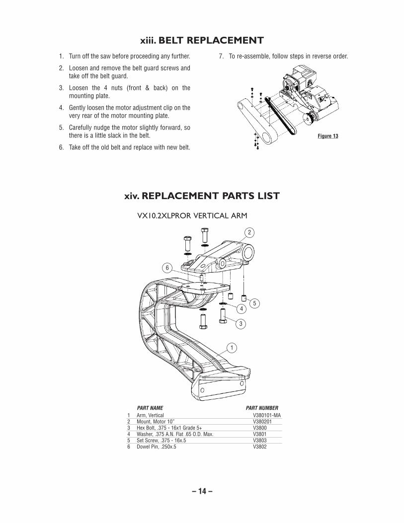
1. Turn off the saw before proceeding any further.
2. Loosen and remove the belt guard screws andtake off the belt guard.
3. Loosen the 4 nuts (front & back) on themounting plate.
4. Gently loosen the motor adjustment clip on thevery rear of the motor mounting plate.
5. Carefully nudge the motor slightly forward, sothere is a little slack in the belt.
6. Take off the old belt and replace with new belt.
7. To re-assemble, follow steps in reverse order.
xiii. BELT REPLACEMENT
xiv. REPLACEMENT PARTS LIST
Figure 13
vX10.2XlprOr vertical arM
asseMbly
1 Arm, Vertical V380101-MA2 Mount, Motor 10” V3802013 Hex Bolt, .375 - 16x1 Grade 5+ V38004 Washer, .375 A.N. Flat .65 O.D. Max. V38015 Set Screw, .375 - 16x.5 V38036 Dowel Pin, .250x.5 V3802
PART NAME PART NUMBER
1
3
45
2
6

– 15 –
vX10.2XlprOr MOtOr asseMbly
1 Power Cable PSV10010R2 Motor Fan Cover PSV100112A Motor Fan PSV100343 Running Capacitor PSV100123A Running Capacitor Cover S800-05.14 Starter Capacitor PSV100134A Starter Capacitor Cover S1000-02.65 2 HP Electrical Industrial Motor PSV100146 Motor Shaft Pulley PSV100157 Belt Guard PSV100168 Belt Guard Bracket PSV100179 Motor Support Shaft PSV1001810 Blade Shaft Pulley PSV1001911 Pulley Lock Pin PSV0001112 Bearing Housing Hold Down Bracket PSV0000913 Blade Cleaning Brushes (2 ea.) PSV1002014 Water Flow "L" Adapter PSV0000815 Blade Guard PSV1002116 Blade Guard Adjustment Knob PSV1002216A Blade Guard Pivot Screw S1000-19.116B Bearing Housing Screws & Nuts PSV0703816C Washer PSV031017 Water Flow "L" Adapter PSV0000818 Water Flow "T" Adapter PSV0000519 Rubber Splash Guard PSV10023
20 Switch Box Cover with Gasket PSV0002LR21 Toggle Switch PSV00001R22 Circuit Breaker PSV1002423 Motor Adjustment Clip PSV1002524 Mounting Plate PSV10026R25 #25 Rubber Belt PSV1002726 Bearing Attached to Pulley PSV1002827 Blade Shaft PSV0000328 Liquid Cooled Bearing Housing PSV00001028A Water “I” Adapter for Bearing Housing PSV0071029 Bearing attached to Inner Flange PSV1002930 Inner Flange PSV1003031 10" Blade DTL10HPXL32 Outer Flange PSV1003133 Blade Lock Nut PSV0000434 Water Pump PSV0000635 Water Tubing PSV00040R36 Belt Guard Screws (3) PSV0703337 Screen Filter Cover PSV00006S37A Water Control Coupling V3501737B Volutes for Water Pump PSV00006-V38 Switch Box PSV00002R39 Switch Box Bracket PSV10026R40 Water Pump Receptacle PSV10033R41 Connectors (3) PSV10032R
PART NAME PART NUMBER PART NAME PART NUMBER
1
23 24
23 2A3A44A
5
6
7
36
8
8A9
10
11
25
12
2627
28
28A 2930
3132
3313
14
15
16
16A
16B
2238 21 20 19 18 17
34
3737A
39
4141A
40
35
37B
16C

– 16 –
1 Base Assembly V310002 Carriage Assembly (Complete) V31100SS3 Table Assembly V380000-M4 Washer, Flat: .375 SAE V38095 Hex Bolt, Grd. 5 Min., .375 - 16UNCx3 V38066 Hex Bolt, Grd. 5 Min., .375 - 16UNCx3.5 V38077 Bumper Stop 121428 Socket Head Cap Screw, Plated .25 - 20UNC x.625 V38089 T-Bolt V38020710 10” Cutting Head V38040011 Vertical Arm Assembly V38020012 Shaft, Pivot V380202-MA13 Handle, Adjustable 6270K3414 Fender Washer, Metric V381115 Bolt, .10mm x 25 V381216 Washer, Lock 10mm V3813
PART NAME PART NUMBER
3
17
6
13411 12
5 410
14
8
2
vX10.2XlprOr
Main asseMbly
15
9
16
– 17 –
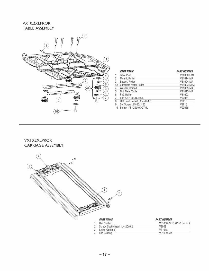
1 Table Plan V380001-MA2 Mount, Roller V31014-MA3 Spacer, Roller V31004-MA4A Complete Metal Roller V31003-SPM4 Washer, Coined V31005-MA5 Nut Plate, Table V31015-MA6 PVC Roller V310037 Bolt 1/4''-20UNCx32L V030518 Flat Head Socket, .25-20x1.5 V38159 Set Screw, .25-20x1.25 V381610 Screw 1/4''-20UNCx27.5L V03056
PART NAME PART NUMBER
9
8
1
436347
2
5
vX10.2XlprOr
table asseMbly
1 Rail Guides V31008SS 10.2PRO Set of 22 Screw, Sockethead, 1/4-20x6.2 V38083 Shim (Optional) V310184 End Casting V31009-MA
PART NAME PART NUMBER
3
4
12
vX10.2XlprOr
carriage asseMbly
{{4A10

– 18 –
1A Complete Metal Roller V31003-SPM1 Bolt 1/4''-20UNCx32L V030512 Washer, Coined V31005-MA3 Spacer, Roller V31004-MA4 Metal Roller (use only with stainless steel rails) V31003M5 Base, Sub-Assembly V310006 Rubber Feet for Frame (set of four) V3100107 Pivot, Adjuster V31002-MA8 Screw, Sockethead 5/16-18x2 121789 Bushing, Pin Lock V31016-MA10 Chain V31017-A11 Pin, Lock V31017-B12 Ring V31017-C
PART NAME PART NUMBER
9
12
11
8
7
1
2
33 4
56
vX10.2XlprOr
base asseMbly
10
23
{1A
– 19 –
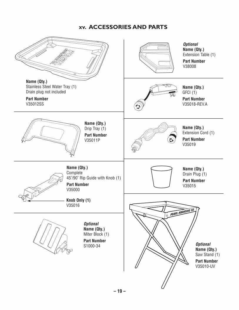
xv. ACCESSORIES AND PARTS
OptionalName (Qty.)Saw Stand (1)Part NumberV35010-UV
Part NumberV35012SS
OptionalName (Qty.)Miter Block (1)Part NumberS1000-34
Name (Qty.)Drip Tray (1)Part NumberV35011P
Name (Qty.)Stainless Steel Water Tray (1)Drain plug not included
Name (Qty.)Drain Plug (1)Part NumberV35015
Name (Qty.)Complete45˚/90˚ Rip Guide with Knob (1)Part NumberV35000
Knob Only (1)V35016
OptionalName (Qty.)Extension Table (1)Part NumberV38008
Name (Qty.)GFCI (1)Part NumberV35018-REV.A
Name (Qty.)Extension Cord (1)Part NumberV35019
– 20 –
xvii. HOW TO ORDER PARTS
Please have the following information ready before calling:
• Serial Number of your Tile Saw
• Model Number of the Tile Saw
• When purchased and where
• Part Description
All parts listed may be ordered from your Local warehouses. If the part is not stocked locally, call our Corporate office andask for our Customer Service Department. For Technical Support call 1-800-969-5561. In Canada call 1-800-387-0008.There is a $25.00 minimum order.
Return Policy: Return goods for credit or exchange on the basis of the following terms: (1) They must be current products; (2) Items returned for replacement or refund should be in original cartons and must be accompanied by a packing slip withthe following information: Returned Goods Authorization (RGA) number obtainable from Customer Service Department •List of items returned • Reason(s) for return(s) • Copy of original invoice(s); (3) Freight charges must be assumed bysender; (4) Returning goods are subject to a 15% handling charge to cover our cost of repacking and restocking. All Pricesare subject to change without notice.
Disclaimer: Pearl Abrasive Co. reserves the right to make changes or improvements on its products without incurring anadditional obligation including any obligation to make corresponding changes or improvements to products previouslymanufactured or sold. Pearl reserves the right to discontinue products at any time without notice.
All illustrations displayed in this manual are the property of Pearl Abrasive Co. and shall not be duplicated or reproducedwithout the express written consent of Pearl Abrasive Co.
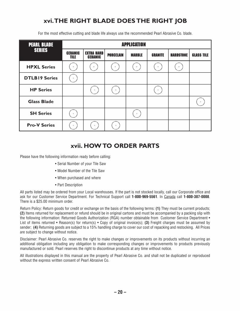
xvi. THE RIGHT BLADE DOES THE RIGHT JOB
For the most effective cutting and blade life always use the recommended Pearl Abrasive Co. blade.
APPLICATIONPEARL BLADESERIES
HPXL Series
DTLB19 Series
HP Series
Glass Blade
SH Series
Pro-V Series
CERAMIC EXTRA HARD PORCELAIN MARBLE GRANITE HARDSTONE GLASS TILETILE CERAMIC

– 21 –
xviii. ELECTRICAL MOTOR SPECIFICATION
Recommendations:
• It is recommended that a 15 amp circuit beused while operating this saw. This willprevent possible power interruption or loss.
• Always plug saw as close as possible to thepower source while operating. This willallow you to receive optimum electricity.
Black
GreenMotor
Gree
n
Wiring Box
Black
White White White
Overcurrent Breaker
Switch
Power Outlet for Water Pump
WARNING:To avoid permanent motor damage you must usethe correct extension cord. Never use more thanone extension cord at a time. Follow the chartfor proper size.
WIREGAUGE
No. 12
No. 10
No. 8
No. 6
LENGTH OF CORD
2 hp115V
25'
50v
75'
–
Horse Power 2 hpVolts 115 V/ 60hzAmps 15 ampsMotor RPM 3420 rpmCycle 60Phase 1Class EBlade Shaft 3200 rpm
VX10.2XLPROR
VX10.2XLPROR

– 22 –
EXCESSIVE NOISE. Possible blade shaft bearing wear,motor belt loose or motor fan rubbing on housing. Havetool serviced.
BLADE WILL NOT CUT. Check for worn out diamond edge.Be sure that the arrow on the blade is rotating the samedirection as the motor arbor and/or arrow on the bladeguard. Make sure the blade is suitable for the material to becut. If blade has been used to cut a material that is hard, itmay have become dull, dress the blade by cutting a lightweight abrasive building block to expose fresh diamonds.Blade dressing stones are available from your local PearlWarehouse.
MOTOR WILL NOT START. Check power supply. If thewater pump turns on when the power switch is in the “on”position, but the motor does not, have the motor serviced.
MOTOR WILL NOT STOP. The contacts in the switch mayhave become arched together in the on position, have itserviced.
MOTOR SHUTS OFF DURING OPERATION. Check to seethat the circuit you are using is not overloaded with lightsor other equipment. The fuse or circuit breaker may nothave sufficient capacity, use 20-amp power. If you areusing an extension cord check the extension cord table tobe sure it is heavy enough to carry the current this productwill draw. See Page 21 for electric cord reference.
EXCESSIVE VIBRATION Check to see that the blade ismounted properly according to safe operating practicessection. Blade may be out of balance, try a different blade.Arbor shaft bearings possibly worn, have tool serviced.
NOT CUTTING SQUARE. Check the main table and carriageadjustment as well as the blade alignment procedurelocated in the care and maintenance section.
MAIN TABLE DOES NOT MOVE FREELY. Inspect the guiderails and rollers for build up of tile chips or dry slurrydeposits. Clean and check guide roll or adjustments,according to the procedure in the care and maintenancesection.
NO WATER FLOW TO BLADE. Check the water feed tubefor kinks or obstructions. Check the inlet screen to ensureit is not clogged. Remove the pump inlet and turn theimpeller to ensure it is not damaged or jammed. Clean theimpeller if necessary and apply a drop of light oil to theshaft - be sure the impeller spins freely.
POOR MACHINE PERFORMANCE WITH LITTLE POWER.Check cord/extension cable for appropriate length andgage. Check power network for sufficient power and circuitbreaker capacity.
CENTER HOLE IN BLADE OVERSIZE OR WORN. Saw bladehas slipped on shaft while running. Check shaft for damageand replace blade.
xix. TROUBLESHOOTING
For your safety and the safety of others, turn the power switch off and always remove theplug from power source before troubleshooting. Repairs performed by unauthorized personnel could causeserious hazard. We recommend that service to this tool be performed by a qualified service technician withoriginal equipment replacement parts.
WARNING!

– 23 –

Part No. VX10XLPROMAN • 04/14
GEORGIA • USA4963 SOUTH ROYAL ATLANTA DRIVE
TUCKER, GA 30084-5024
ONTARIO • CANADA375-2 PIDO ROAD
PETERBOROUGH, ONTARIO K9J-6X7
CORPORATE OFFICE: SO. CALIFORNIA • USA6832 E. SLAUSON AVENUE, COMMERCE, CA 90040-0031
562-927-5561 • FAX 562-928-3857Toll Free: 800-969-5561www.pearlabrasive.com