Embed Size (px)
Citation preview
MODELING AND ANALYSIS OF ATTACKS AND COUNTER DEFENSE
MECHANISMS FOR CYBER PHYSICAL SYSTEMS
-Robert Mitchell, Ing-Ray Chen, Member, IEEE
Presented By,Manasa AnanthKritika Mathur

Agenda
• Introduction• Objective• System Model
• System Description• Attacker Behavior Modeling• System Failure Definition - Countermeasures
• Performance Model – SPN Model• Performance Analysis• Conclusion
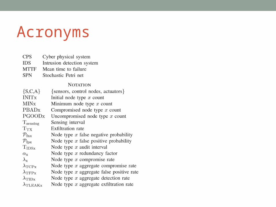
Acronyms

Introduction• Cyber Physical System (CPS)
• is a system of collaborating computational elements controlling physical entities.
• Two lines of research in modeling and analysis of CPSs,• Focused on a formal process or framework for designing and engineering a CPS - formalize safety and functional requirements utilizing formal modeling and analysis tools and then perform rigorous model verification.
• Focused on a mathematical model for analyzing the system’s response behavior in the presence of malicious nodes performing various attacks

Objective• Based on second line of research work,
• Develop a state-based stochastic process to model a CPS equipped with an intrusion detection system (IDS) presented with various types of attacks, including random, opportunistic and insidious, with the objective to improve IDS designs so as to prolong the system lifetime.
• Primary Objective• To capture the dynamics between adversary behavior
and defense for survivability of CPSs.
• End product • Tool that is capable of analyzing a myriad of attacker
behaviors and seeing the effectiveness of countering adaptive defense strategies which incorporate attack/response dynamics.
System Model
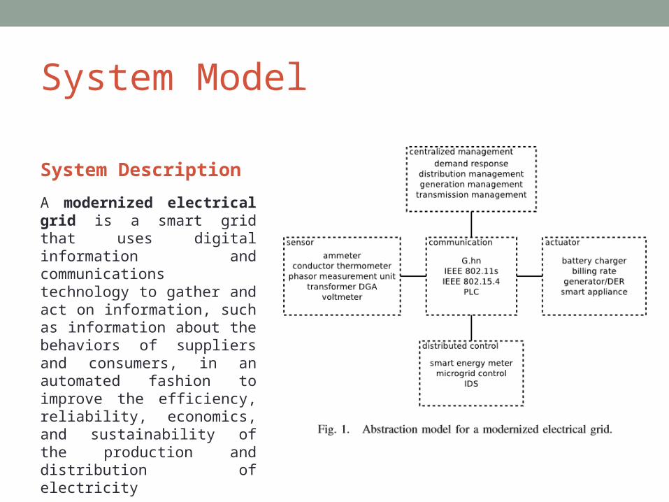
System Description
A modernized electrical grid is a smart grid that uses digital information and communications technology to gather and act on information, such as information about the behaviors of suppliers and consumers, in an automated fashion to improve the efficiency, reliability, economics, and sustainability of the production and distribution of electricity

System Description Cont’d
Five types of Physical Devices
1. Centralized Management• Perform system-wide management functions• Attended• Physically secure• High Performance
2. Sensors• Translate measurements of the physical world into the
cyber domain• Unattended• Physically vulnerable
System Description Cont’d
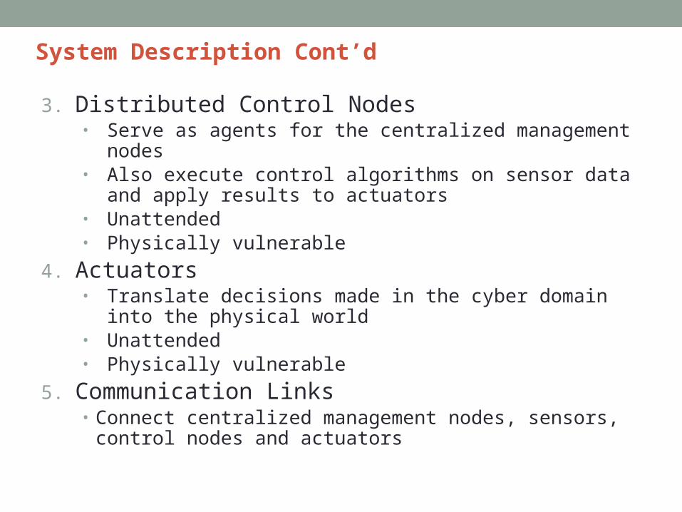
3. Distributed Control Nodes• Serve as agents for the centralized management nodes• Also execute control algorithms on sensor data and
apply results to actuators• Unattended• Physically vulnerable
4. Actuators• Translate decisions made in the cyber domain into the
physical world• Unattended• Physically vulnerable
5. Communication Links• Connect centralized management nodes, sensors,
control nodes and actuators

Attacker Behavior Modeling
•Surveilling Attacker•This brand of attacker seeks to gain information about or information residing on the target system
•In a commercial domain, a company would do this to steal trade secrets from a competitor
•Interested in centralized management nodes, communications links and sensors
•Destructive attacker•This brand of attacker seeks to disrupt the target system•In the law enforcement domain, a political group would do this to disrupt some entity with a different worldview.
•Interested in actuators, centralized management nodes and control nodes

System Failure Definition - Countermeasures
• Attrition Failure • Occurs when the modernized electrical grid doesn't have enough
control nodes or actuators to accomplish its intended work• Sensors are not considered towards attrition failure
• Reasons:• If a sensor is compromised – it will send illegitimate data to
control node, which would be drowned by the legitimate data sent by a great number of uncompromised nodes
• If a sensor is evicted – there is minimal short-term impact as any control loop can run free of external input long enough to restore it.
• Attacker – Destructive Attacker• Countermeasure
• Redundancy - Modern electrical grid systems use some degree of redundancy to counterbalance failed, evicted and compromised nodes.
• Design parameter is redundancy factor (αX) over the minimum number of nodes (MINX) required for the functionality.
• INITX = MINX * αX where x belongs to {C, A}

System Failure Definition - Countermeasures
• Pervasion Failure • Occurs when the density of compromised control nodes or
actuators is too high. Here the compromised nodes collude to overwhelm the other nodes.
• Sensors are not considered towards pervasion failure• Reason:• If a sensor is compromised – it has no means to directly or
indirectly attack the modernized electrical grid.• Attacker – Destructive Attacker• Countermeasure
• Redundancy - Modern electrical grid systems use some degree of redundancy to counterbalance failed, evicted and compromised nodes.
• Design parameter is redundancy factor (αX) over the minimum number of nodes (MINX) required for the functionality.
• INITX = MINX * αX where x belongs to {C, A}
System Failure Definition - Countermeasures
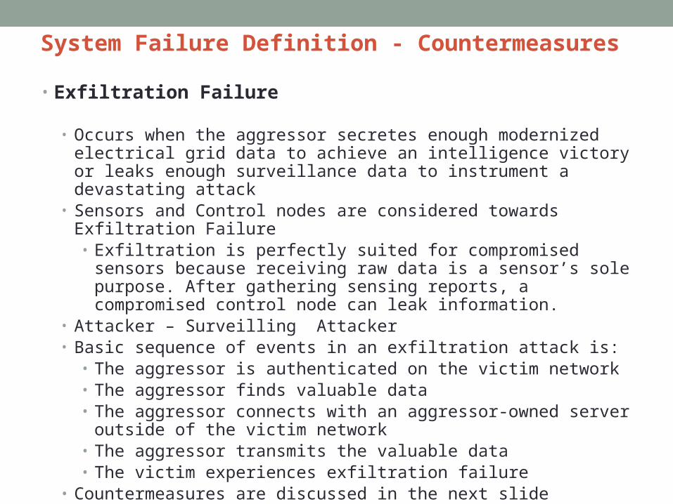
• Exfiltration Failure
• Occurs when the aggressor secretes enough modernized electrical grid data to achieve an intelligence victory or leaks enough surveillance data to instrument a devastating attack
• Sensors and Control nodes are considered towards Exfiltration Failure • Exfiltration is perfectly suited for compromised sensors
because receiving raw data is a sensor’s sole purpose. After gathering sensing reports, a compromised control node can leak information.
• Attacker – Surveilling Attacker• Basic sequence of events in an exfiltration attack is:
• The aggressor is authenticated on the victim network• The aggressor finds valuable data• The aggressor connects with an aggressor-owned server
outside of the victim network• The aggressor transmits the valuable data• The victim experiences exfiltration failure
• Countermeasures are discussed in the next slide

System Failure Definition - Countermeasures
• Exfiltration Failure Countermeasures • Intrusion detection
• System equipped with IDS applying anomaly or signature based detection technique to detect and evict suspicious nodes
• Intrusion detection quality is characterized by the input parameters - false negative probability (Pfnx) and false positive probability (Pfpx) with X belongs to {S, C, A}
• False negative probability – Probability that a malicious node is misdetected• False positive probability – Probability that a good node is misidentified as
malicious node• Countermeasure employed by the CPS to detect and evict malicious nodes is to apply
the optimal detection interval TIDSX for periodic intrusion detection with X belongs to {S, C, A}
• Pfnx ↓ => TIDSX ↓ - malicious nodes can be detected and evicted often
• Pfpx ↑ => TIDSX ↑ - good nodes should not be misidentified and evicted often
• Data leak rate control• The CPS runs an inward facing firewall to cope with the compromised sensors and
control nodes• The firewall either denies the connection or throttles the outbound session speed,
thus buying more detection time• Design parameter – Maximum transmission rate TTX bits per second
• To cope with the compromised sensor the system limits data leak rate by rotating one sensor among all sensors that measure the same physical phenomenon to do sensing and data transmission per sensing interval (Tsensing).
• Design parameter is Tsensing, with which data leak is possible only when the compromised sensor node is rotated to do sensing
• If a sensor performs data transmission in every Tsensing interval, the IDS generates a detection

System Failure Definition – Countermeasures Summary
Performance Model – SPN Model
Underlying Semi – Markov models
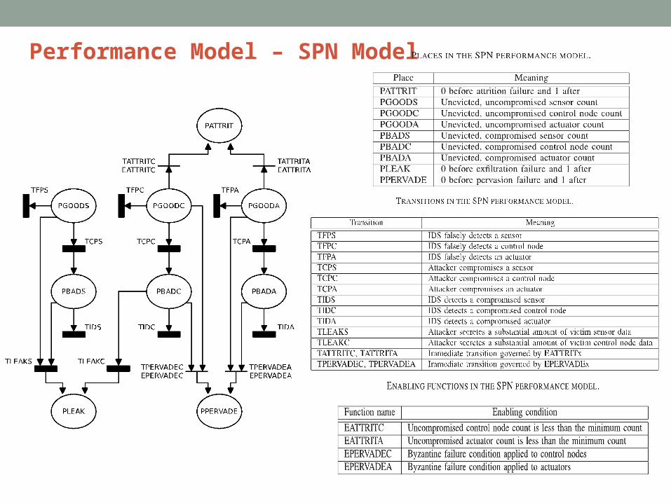
• SPN Model – System initialization is done by populating the system with INITx nodes with x ∈ {S,C,A}.
• Places are used to hold tokens with each representing one node
• Initially, all nodes are uncompromised and put in places PGOODx as tokens
• The underlying model would be Markov if transition times were exponentially distributed. However, this is a strong assumption, hence a semi-Markov model is used to underlie the SPN to accommodate generally distributed transition times.
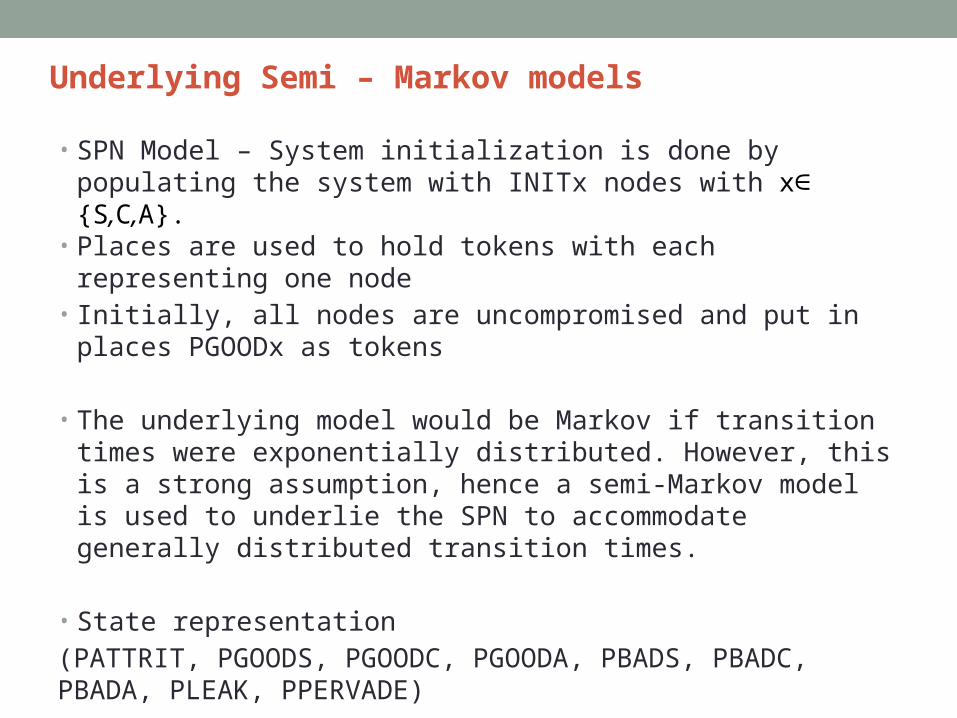
• State representation(PATTRIT, PGOODS, PGOODC, PGOODA, PBADS, PBADC, PBADA, PLEAK, PPERVADE)

Underlying Semi – Markov models
➢Adversary compromising an uncompromised node
(PATTRIT, PGOODS, PGOODC, PGOODA, PBADS, PBADC, PBADA, PLEAK, PPERVADE)
➢Modeled by transitions TCPX in the SPN model
➢λTCPx represents the rate at which an uncompromised node becomes a compromised node because of the capture event
➢For example, if in state (0, ns, nc, na, 0, 0, 0, 0, 0) an uncompromised sensor node is compromised, a token will flow from PGOODS to PBADS and the resulting state is (0, ns-1, nc, na, 1, 0, 0, 0, 0)
Underlying Semi – Markov models
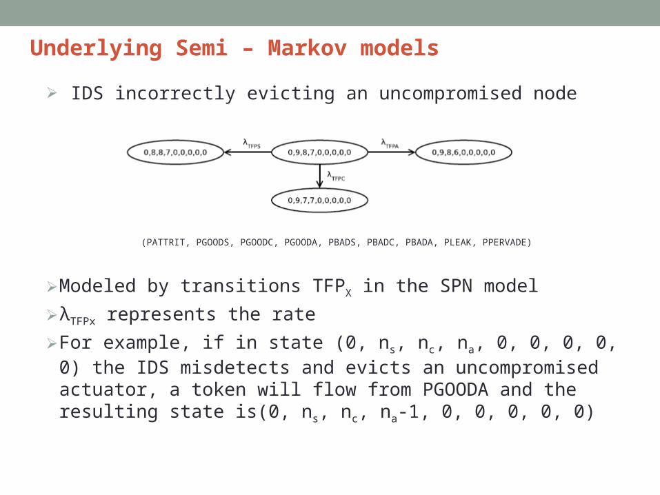
➢ IDS incorrectly evicting an uncompromised node
(PATTRIT, PGOODS, PGOODC, PGOODA, PBADS, PBADC, PBADA, PLEAK, PPERVADE)
➢Modeled by transitions TFPX in the SPN model
➢λTFPx represents the rate
➢For example, if in state (0, ns, nc, na, 0, 0, 0, 0, 0) the IDS misdetects and evicts an uncompromised actuator, a token will flow from PGOODA and the resulting state is(0, ns, nc, na-1, 0, 0, 0, 0, 0)
Underlying Semi – Markov models
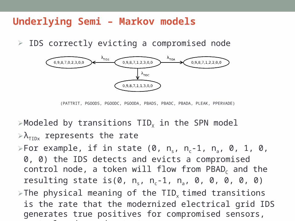
➢ IDS correctly evicting a compromised node
(PATTRIT, PGOODS, PGOODC, PGOODA, PBADS, PBADC, PBADA, PLEAK, PPERVADE)
➢Modeled by transitions TIDX in the SPN model
➢λTIDx represents the rate
➢For example, if in state (0, ns, nc-1, na, 0, 1, 0, 0, 0) the IDS detects and evicts a compromised control node, a token will flow from PBADC and the resulting state is(0, ns, nc-1, na, 0, 0, 0, 0, 0)
➢The physical meaning of the TIDx timed transitions is the rate that the modernized electrical grid IDS generates true positives for compromised sensors, control nodes and actuators

Underlying Semi – Markov models
➢ System failure due to attrition
(PATTRIT, PGOODS, PGOODC, PGOODA, PBADS, PBADC, PBADA, PLEAK, PPERVADE)
➢TATTRITX ,x ∈ {C,A} models attrition failure event➢Transition is enabled when number of node type X is less
than the minimum specified MINX
Underlying Semi – Markov models
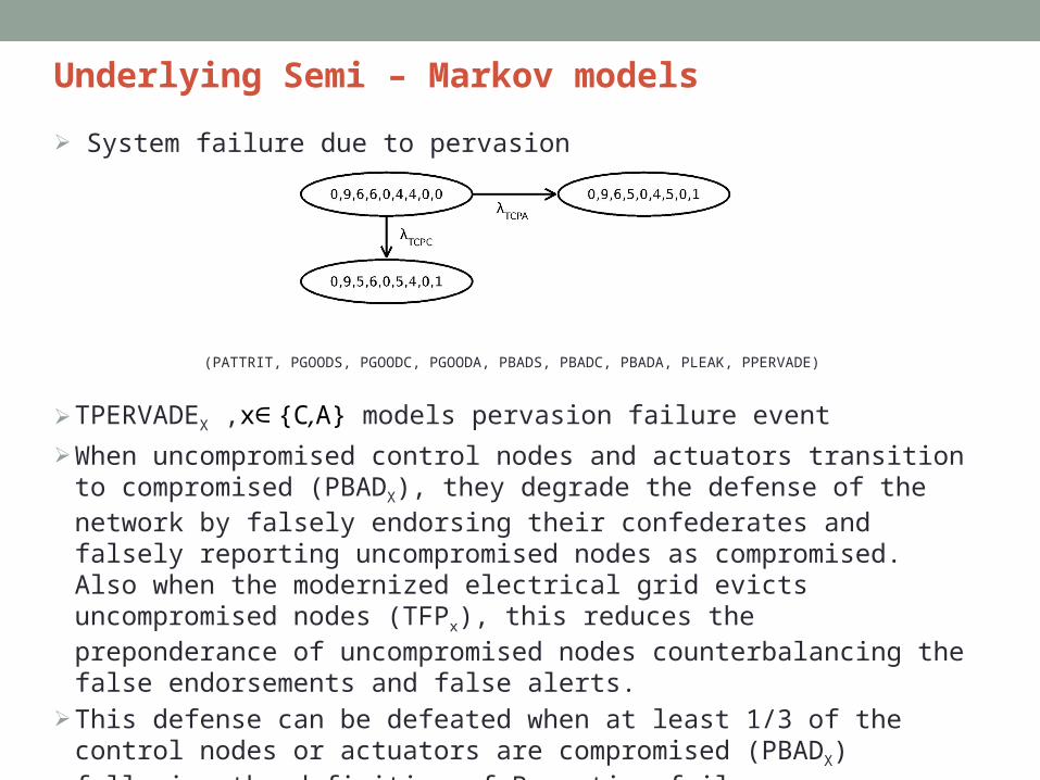
➢ System failure due to pervasion
(PATTRIT, PGOODS, PGOODC, PGOODA, PBADS, PBADC, PBADA, PLEAK, PPERVADE)
➢TPERVADEX ,x∈ {C,A} models pervasion failure event
➢When uncompromised control nodes and actuators transition to compromised (PBADX), they degrade the defense of the network by falsely endorsing their confederates and falsely reporting uncompromised nodes as compromised. Also when the modernized electrical grid evicts uncompromised nodes (TFPx), this reduces the preponderance of uncompromised nodes counterbalancing the false endorsements and false alerts.
➢This defense can be defeated when at least 1/3 of the control nodes or actuators are compromised (PBADX) following the definition of Byzantine failure
Underlying Semi – Markov models
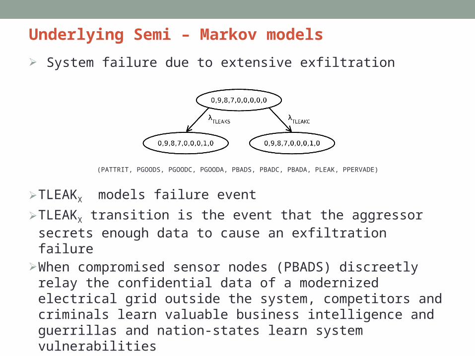
➢ System failure due to extensive exfiltration
(PATTRIT, PGOODS, PGOODC, PGOODA, PBADS, PBADC, PBADA, PLEAK, PPERVADE)
➢TLEAKX models failure event
➢TLEAKX transition is the event that the aggressor secrets enough data to cause an exfiltration failure
➢When compromised sensor nodes (PBADS) discreetly relay the confidential data of a modernized electrical grid outside the system, competitors and criminals learn valuable business intelligence and guerrillas and nation-states learn system vulnerabilities
➢TTX and Tsensing are the countermeasures for this threat

Performance Analysis
• Model ParameterizationTwo Kinds of parameters
• Design parameter is one that the system manager can choose. • Input parameter is one that the operating environment dictates.

Model Parameterization Cont’d
1. Aggregate Compromise Rate λTCPx
λTCPx = |PGOODx| x λx
|PGOODx| = number of uncompromised nodes of device type x and λx = per node compromised rate
• More uncompromised sensors, control nodes or actuators translates to more opportunities for compromise.
2. Aggregate Detection rate λTIDx
λTIDx = |PBADx| x (1-Pfnx)/TIDSx
|PBADx|= number of compromised nodesPfnx = false negative probability
TIDSx is the IDS detection interval for device type x.
• In every TIDSx interval, a bad node of type x will be correctly identified as a bad node with probability 1−Pfnx, so the aggregate rate at which bad nodes are detected and evicted correctly is |PBADx| multiplied with (1−Pfnx)/TIDSx.

Model Parameterization Cont’d
3. Aggregate False Positive Rate λTCPx
λTCPx = |PGOODx| x Pfnx/TIDSx
|PGOODx| = number of uncompromised nodes of device type x and Pfpx is the false positive probability
TIDSx is the IDS detection interval for device type x.
• In every TIDSx interval, a good node of type x will be misidentified as a bad node with probability Pfpx, so the aggregate rate at which good nodes suffer from false positives is |PGOODx| multiplied with Pfpx/TIDSx.
4. Aggregate Sensor Exfiltration Rate λTLEAKS
• First term is for a compromised sensor node to rotate in for reporting sensing data,
• Second term is for the rate at which sensing reporting occurs • Third term is for the maximum number of leaks the system can
tolerate before an exfiltration failure occurs.
Model Parameterization Cont’d
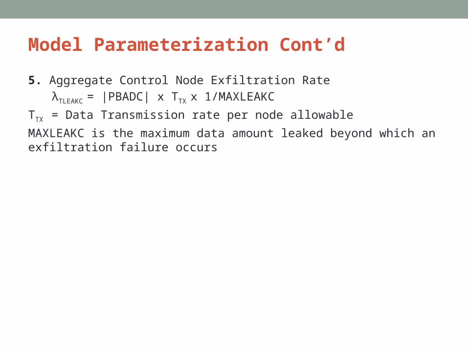
5. Aggregate Control Node Exfiltration RateλTLEAKC = |PBADC| x TTX x 1/MAXLEAKC
TTX = Data Transmission rate per node allowable
MAXLEAKC is the maximum data amount leaked beyond which an exfiltration failure occurs

Results• Numerical data for MTTF assessment as a result of applying
countermeasures (Intrusion Detection , Data Leak Rate Control & Redundancy) against attack behavior (Surveilling and Destructive attacker)causing attrition, pervasion or exfiltration system failure.
Objective: Analyze the effect of countermeasures in terms of the following on MTTF• Intrusion detection interval for node type x ∈ {S,C,A) TIDSx
• False Positive Probability Pfp
• False Negative Probability Pfn
• Effect of redundancy failure αx
Results Cont’d
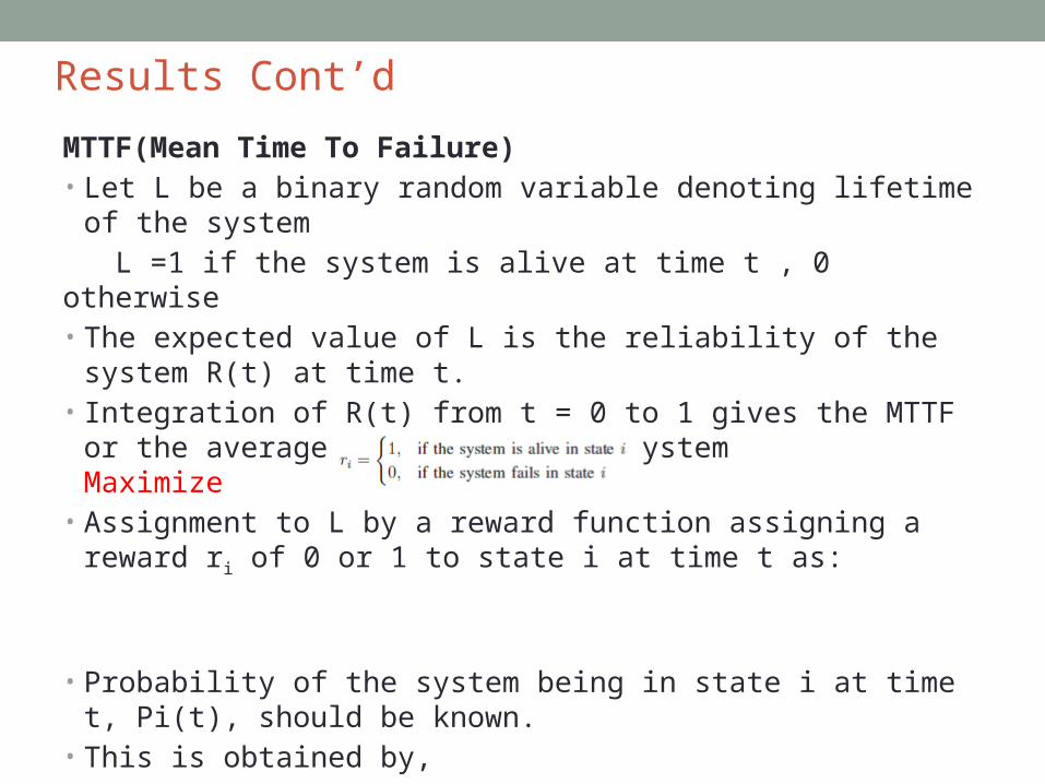
MTTF(Mean Time To Failure)• Let L be a binary random variable denoting lifetime of the system
L =1 if the system is alive at time t , 0 otherwise• The expected value of L is the reliability of the system R(t) at time t. • Integration of R(t) from t = 0 to 1 gives the MTTF or the average lifetime of
the system Maximize • Assignment to L by a reward function assigning a reward ri of 0 or 1 to state
i at time t as:
• Probability of the system being in state i at time t, Pi(t), should be known.• This is obtained by,
➢Defining a SPN model using SPNP ➢Solving the underlying semi-Markov model utilizing solution techniques
such as SOR, Gauss Seidel, or Uniformization.

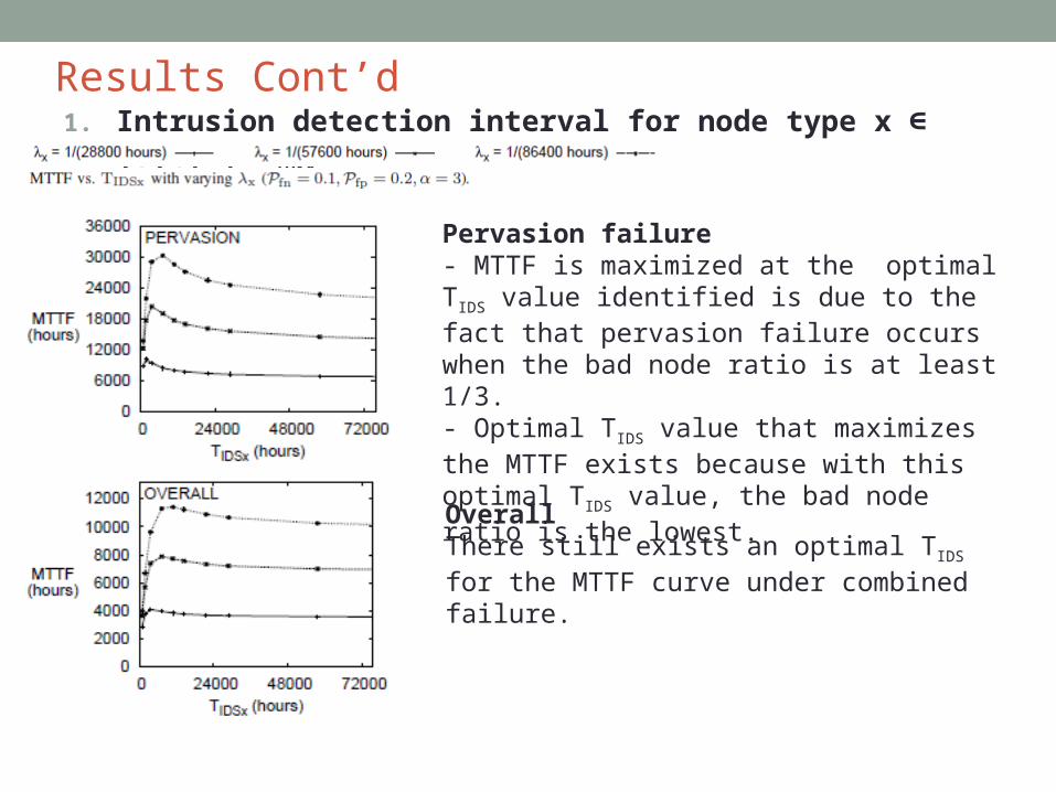
Results Cont’d1. Intrusion detection interval for node type x {S,C,A) T∈ IDSx (MTTF as λx )
Attrition failureMTTF increases as TIDS increases due to setting of Pfn = 0.1 < Pfp = 0.2- Probability that a good node is misidentified as a bad node is higher than that a bad node is missed.- A smaller TIDS, will cause more good nodes to be evicted than bad nodes causing system to fail faster due to attrition failure because of a lack of good nodes in the system.
Exfiltration failureMTTF is maximized at the optimal TIDS because exfiltration failure is affected by the bad node ratio.- In order to maximize MTTF under exfiltrationfailure, one needs to minimize this ratio. - Optimal TIDS that maximizes the MTTF under exfiltration failure exists because the bad node ratio minimizes with this optimal TIDS value.
Results Cont’d1. Intrusion detection interval for node type x {S,C,A) T∈ IDSx
Pervasion failure- MTTF is maximized at the optimal TIDS value identified is due to the fact that pervasion failure occurs when the bad node ratio is at least 1/3.- Optimal TIDS value that maximizes the MTTF exists because with this optimal TIDS value, the bad node ratio is the lowest.
OverallThere still exists an optimal TIDS for the MTTF curve under combined failure.

Results Cont’d2. Effect of false positive probability Pfp (MTTF as Pfp )
MTTF decreases as Pfp increases for all failure types because as Pfp increases there is a higher probability of a good node being misidentified as a bad node and evicted.
Except for attrition failure,there is an optimal TIDS value under which the MTTF is maximized.
TIDS value for MTTFmaximization increases as Pfp increases.
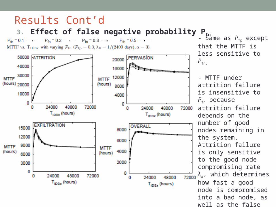
Results Cont’d3. Effect of false negative probability Pfn
- Same as Pfp except that the MTTF is less sensitive to Pfn.
- MTTF under attrition failure is insensitive to Pfn because attrition failure depends on the number of good nodes remaining in the system. Attrition failure is only sensitive to the good node compromising rate λx, which determines how fast a good node is compromised into a bad node, as well as the false positive rate, i.e., Pfp, which determines how fast a good node is misidentified as a bad node and evicted.

Results Cont’d4. Effect of redundancy factor αx
Attrition failure (MTTF as αx )Redundancy factor α determines the number of nodes initially (INITx) with INITx = MINx × αx (where x ∈ {C,A}) MINx is the minimum number of control nodes or actuators.Attrition failure depends on the number of good nodes remaining in the system, putting in more initial nodes can better prevent attrition failure from occurring. Therefore, the MTTF under attrition failure increases as α increases.
Exfiltration Failure (MTTF as αx )Exfiltration failure can occur through TLEAKC/S which depends on the absolute number of bad control nodes/ sensors.λTLEAKC increases as the initial number of “control” nodes increases, i.e., as αC increases, because this increases the chance of bad “control” nodes being produced due to node compromising events. λTLEAKS does not depend on αC.MTTF under exfiltration failure decreases as α increases

Results Cont’d4. Effect of redundancy factor αx
Pervasion failure (MTTF as αx )
MTTF under pervasion failure increases as α increases.Pervasion failure depends on the bad node ratio which decreases as more initial nodes are put in the system ,especially if the detection interval TIDS is largeOverallThere exists an optimal TIDS that maximizes the MTTF of the CPS against all attacks causing attrition, pervasion or exfiltration system failures.
Conclusion
• Developed an analytical model based on SPNs to capture the dynamics between adversary behavior and defense for CPSs.
• Results revealed optimal design conditions including the intrusion detection interval and the redundancy level under which the modernized electrical grid’s MTTF is maximized.
• Redundancy should be used with caution, because while it suppresses attrition and pervasion failure, it also induces exfiltration failure.
Future Work• Investigate how control theory or game theory principles
controlling the attack/defense dynamics can further improve the CPS survivability.