Embed Size (px)
Citation preview

Modeling and Analysis of In-Vessel Melt Retention
and Ex-Vessel Corium Cooling in the U. S.
E. L. Fuller, S. Basu, and H. Esmaili
Office of Nuclear Regulatory Research
United States Nuclear Regulatory Commission
IAEA Technical Conference
Shanghai, China
October 17-21, 2016
1

Outline of Presentation
• Background
• Results and insights gleaned from CPRR ex-vessel corium cooling
studies
• MELCOR 2.1 and MAAP 5.03 core melt progression modeling
– In core region
– In lower head region
– Ex-vessel
• Results and insights from in-vessel retention studies
• Assessment of required model improvements and additional data
requirements
• Conclusions
2
Background: A Regulatory Perspective
• Mechanistic analyses of core melt progression have been carried out
for decades in the US.
– WASH-1400, IDCOR, IPEs, SAMG development, SOARCA, CPRR Rulemaking
support
– Industry used MAAP and NRC used MELCOR
• CPRR Rulemaking support effort explicitly analyzed water addition to
mitigate the effects of core debris exiting the vessel.
– NRC used MELCOR and EPRI used MAAP
– Water addition and water management, along with venting through the Wetwell,
ensure BWR Mark I and Mark II containment building integrity and minimization of
radionuclide releases to the environment
– Analyses also suggest that sufficient time may be available for adding water to the
vessel to prevent vessel failure
• Models in MELCOR and MAAP have been benchmarked against
many experiments.
– Models continue to be enhanced as more information becomes available.
– Model comparison activities are ongoing.
3

Results and Insights from CPRR
Regulatory Support Analyses
• Industry FLEX and (BWROG) EPG/SAG Rev. 3 are assumed to be followed.
• Operators depressurize RPV after RCIC failure; in-vessel injection of fire water possible.
• Time is available after RCIC failure for injection into RPV to possibly prevent vessel failure.
• Containment vents from Wetwell air space before vessel failure, due to significant in-core
hydrogen production.
• Most of volatile fission product releases from fuel occur before containment is vented.
• Fission product releases mitigated by scrubbing in suppression pool.
4
Event Timing (hr) MELCOR 2.1 MAAP 5.03
Water Injected In-Vessel (500 gpm,
later reduced to prevent vent flooding)
No Water
Added
At VF No Water
Added
At VF
RCIC fails (SP temperature is 230 ºF) 9.6 9.6 7.4 7.4
Core uncovers 12.0 11.9 9.1 9.1
Core damage begins 13.7 13.2 9.4 9.4
Containment vented at 75 psia 14.9 14.4 14.7 14.7
Lower head dries out 18.1 18.2 16.9 16.9
Vessel fails 23.0 23.4 23.2 23.2
Some Quantities of Interest
Iodine release fraction to env. (72 hr) 2.3 E-1 7.9 E -2 9.3 E-3 2.9 E-3
Cesium release fraction to (72 hr) 1.9 E-2 6.1 E-3 3.1 E-3 2.0 E-3
Hydrogen produced in vessel, kg 1195 1032 833 833

5
MELCOR 2.1 Picture of In-Vessel
Core Debris Evolution and Motion
• Core degrades mainly as particulate debris that relocates to the lower core plate.
• Axial flow through core never completely blocked by debris.
• Very little molten material in the core region.
• Debris in lower plenum primarily exists as particles; some melting after LP dryout.
• Vessel failure from creep rupture at bottom of lower head (failures at penetrations
neglected).

6
MAAP 5.03 Picture of Melt
Progression and Debris Evolution
(no water addition) • Significant molten pool formed in core region, with surrounding crusts.
• Axial flow through molten pool blocked by crusts.
• Particulate debris, caused by jet breakup of molten pour, in lower plenum at first, with
evolution into molten metal and oxidic layers with a particle bed above. Oxidic crust
separates the molten layers.
• Vessel failure from CRD tube ejection at metal layer level, due to high temperatures caused
by the focusing effect. If penetration failures are neglected, vessel fails from creep rupture
about 6 min later at the same location.

7
Recovery from Injection into RPV
Molten Pool in Core Region at
Various Injection Times (MAAP 5.03)

Recovery from Injection into RPV at
20 hr: Corium and Water in LP (MAAP 5.03)
8

Mark I debris spreading in DW
if no water is added (MELCOR 2.1)
9

No liner melt-through when
water added (MELCOR 2.1)
10
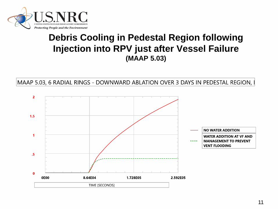
Debris Cooling in Pedestal Region following
Injection into RPV just after Vessel Failure (MAAP 5.03)
11

12
Details on Water and Corium Depths and
Ablation of Concrete In Drywell and Pedestal (MAAP 5.03)
• Water accumulates early because of seal LOCAs in the recirculation pumps
• Corium cooling mechanisms modeled are • bulk cooling when water is first added,
• water ingression (penetration through the crust and into the corium pool),
• and melt eruptions when off-gases entrain molten corium.
• Ablation terminated within a few hours, mostly due to water ingression.

13
Delayed Injection is Better Than
No Injection at All

Summary of Results and Insights
from CPRR Supporting Analyses
• MELCOR 2.1 and MAAP 5.03 agree well for all cases run by
both.
• The models appear to be appropriate for severe accident
mitigation analyses. Uncertainty and sensitivity studies should
accompany these analyses.
• A combination of venting and water addition is required to
maintain containment structural integrity.
• Water addition, either into the RPV or into the Drywell after
vessel failure, may prevent liner melt-through and acts to
minimize fission product releases.
• Wetwell venting and consequent early fission product releases
occurred before vessel failure in most of the sequences.
• If the RPV is depressurized sufficiently before core damage,
then timely water injection into the RPV can arrest core damage,
reduce fission product release, and prevent vessel failure.
14

MAAP 5.04 (Just Released) Paints a
Different Picture Of the Focusing
Effect and Failure at Penetrations: Is
This Picture Plausible?
15
• Instrument tubes fill with molten core debris
in core region.
• Molten debris re-freezes in instrument tubes
and plugs form, particularly at the
penetration locations.
• Instant stratification into a particle bed over
metal and oxidic layers no longer assumed,
but is calculated. The effect is to diminish
the role of the metal layer.
• Earlier vessel failure predicted due to failure
of closure welds from transfer of heat in the
plugs.
• Consequently, in-vessel recovery may be
less likely if water is added.

Future Research Needs
• Phenomenological Research
• No fundamentally new severe accident phenomena
identified for LWR technology, although core melt
progression details need to be better understood
• Some previously identified phenomena require additional
attention
• Melt progression, particularly, late phase
• Hydrogen risk
• Ex-vessel melt behavior (coolability and FCI)
• Mitigation system performance
16

Accident Management Perspective
17
• Severe accident management guidelines are
being re-examined in light of Fukushima
• In-vessel injection is being thought of as the
preferred water addition option for BWRs, to
possibly prevent vessel failure, or to cool core
debris ex-vessel
• Should the cavity be flooded prior to vessel
failure? How deep? – Steam explosion potential in
a deep pool?
• Should cavity be flooded at or shortly after vessel
failure?

Improvement of Analysis Tools
• Phenomenological modeling
• Late phase melt progression, melt quenching and
fragmentation, melt spreading and debris coolability
• Combustible gas transport and stratification
– MAAP 5.04 addresses this need
• Fission product chemistry (aqueous iodine, ruthenium)
and transport
• Pool scrubbing under saturated conditions
• Mitigation system modeling
• Engineered safety features
• Operator actions (EOP, FSG, SAMG)
• Reduction of residual uncertainties
18

Concluding Remarks
• Needs
• Post-TMI thrust on accident prevention and SA issue
resolution
• Post-Fukushima thinking: balance between prevention and
mitigation; R&D needs on mitigation
• Challenges • Much knowledge gained on severe accidents but workforce
is ageing
• Budget reality
• Opportunities • R&D optimization and knowledge preservation
• Increased collaboration among international research
communities
19