Embed Size (px)
Citation preview
Research ArticleModeling and Simulation of a Moving Yarn SegmentBased on the Absolute Nodal Coordinate Formulation
Shujia Li1 YongxingWang 12 XunxunMa1 and ShengzeWang12
1College of Mechanical Engineering Donghua University Shanghai 201620 China2Research Center of Advanced Textile Machinery Ministry of Education Donghua University Shanghai 201620 China
Correspondence should be addressed to Yongxing Wang wangyxdhueducn
Received 13 March 2019 Accepted 9 July 2019 Published 25 July 2019
Academic Editor Gaetano Giunta
Copyright copy 2019 Shujia Li et alThis is an open access article distributed under the Creative Commons Attribution License whichpermits unrestricted use distribution and reproduction in any medium provided the original work is properly cited
A new finite element dynamic model of a moving yarn segment has been proposed in this paper based on the absolute nodalcoordinate formulation (ANCF) Apart from taking into account the elastic properties of the yarn in three dimensions the modelalso considers the viscosity in the longitudinal direction and takes into account the effect of gravity and air resistance In this paperthe simulation described the movement of the yarn segment that is pulled by the fixer on the guideway Then a correspondingexperiment was proposed to evaluate the theoretical model The theoretical and experimental comparisons of the motion tracingexhibited good agreement demonstrating that the newmodel could predict the actual moving trace of the yarn segmentMoreoveranother simulation of the spatial motion of the yarn segment was presented to elucidate the role of the model in predicting themovement of the yarn segment After considering the parameters of the actual process and its constraints the authors establishedthat the proposed model could be used to predict the trajectory of a yarn segment in the actual production process which is vitalwhen fabricating textile products
1 Introduction
As the intermediate component and fundamental constituentof the process of turning fiber into fabric in the textileindustry the quality of the yarn directly affects the quality ofthe final textile productThere are different types of yarn suchas twisted yarns or continuous filaments that are not twistedHereafter in this paper both types have been collectivelyreferred to as ldquoyarnrdquo
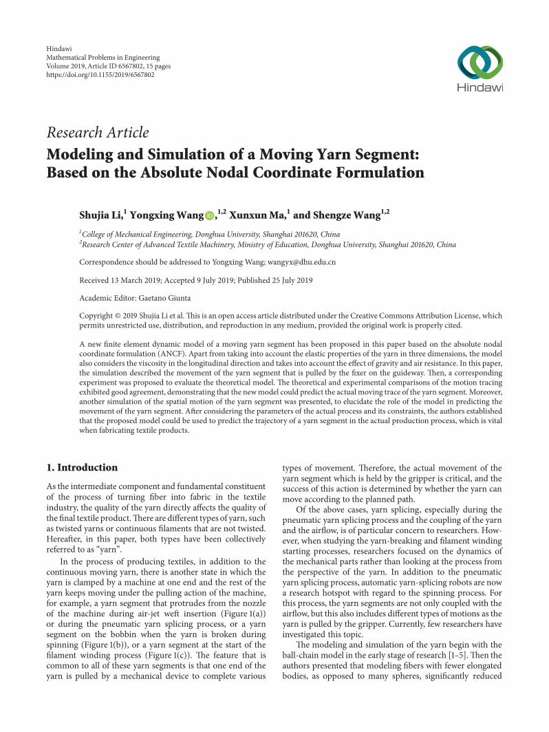
In the process of producing textiles in addition to thecontinuous moving yarn there is another state in which theyarn is clamped by a machine at one end and the rest of theyarn keeps moving under the pulling action of the machinefor example a yarn segment that protrudes from the nozzleof the machine during air-jet weft insertion (Figure 1(a))or during the pneumatic yarn splicing process or a yarnsegment on the bobbin when the yarn is broken duringspinning (Figure 1(b)) or a yarn segment at the start of thefilament winding process (Figure 1(c)) The feature that iscommon to all of these yarn segments is that one end of theyarn is pulled by a mechanical device to complete various
types of movement Therefore the actual movement of theyarn segment which is held by the gripper is critical and thesuccess of this action is determined by whether the yarn canmove according to the planned path
Of the above cases yarn splicing especially during thepneumatic yarn splicing process and the coupling of the yarnand the airflow is of particular concern to researchers How-ever when studying the yarn-breaking and filament windingstarting processes researchers focused on the dynamics ofthe mechanical parts rather than looking at the process fromthe perspective of the yarn In addition to the pneumaticyarn splicing process automatic yarn-splicing robots are nowa research hotspot with regard to the spinning process Forthis process the yarn segments are not only coupled with theairflow but this also includes different types of motions as theyarn is pulled by the gripper Currently few researchers haveinvestigated this topic
The modeling and simulation of the yarn begin with theball-chain model in the early stage of research [1ndash5]Then theauthors presented that modeling fibers with fewer elongatedbodies as opposed to many spheres significantly reduced
HindawiMathematical Problems in EngineeringVolume 2019 Article ID 6567802 15 pageshttpsdoiorg10115520196567802
2 Mathematical Problems in Engineering
Yarnsegment
(a)
Yarnsegment
(b)
Filamentsegment
(c)
Figure 1 Different yarn segments in the textile process (a) yarn segment in the spinning when yarn-breaking (b) yarn segment in thespinning when yarn-breaking (c) yarn segment in filament winding starting process
computation time and facilitated the study of interacting longfibers [5] This prompted researchers to use the slender bodyunit to simulate the modeling of yarns Swop and Amesused the moving string model to study the movement ofthe yarn during the textile production process [6] StanislavPracek studied the yarn unwinding process based on thestring motion theory [7]The dynamic string model is widelyused for analyzing the characteristics of the yarn when it ismoving in the longitudinal direction such as vibration Inaddition to moving strings the rope rod and beam elementsare also typical slender bodies A study [8] used a rod elementand frictionless pins to create a digital chain which was usedto describe the yarn but it had massive computation Theapplication of beam element in textile modeling research ismostly used to establish yarn element in fabrics [9] Gao et al[10] proposed that because fiber tows length wasmuch higherthan their transverse dimensions beam elements seemed tobe the most convenient structural finite element tool theauthors introduced a new 3D beam element with sectionchanges for large-scale textile modeling but it still stayed onthe small transformation case
The movements of the yarn segments are three-dimensional and during the movement the yarn segmentundergoes deformation such as stretching torsion bendingand shearing in the various processes and they are affectedby air resistance A three-dimensional description is neededto fully consider the yarnrsquos deformation and motion inthe longitudinal direction as well as its cross-sectiondimensions This has led to an exciting attempt to simulatethe yarn segment using a three-dimensional beam elementMeanwhile the viscosity of the yarn in the longitudinaldimension which is the main direction of tension cannotbe ignored in the analysis In finite element beam theoriesthere are classical models that come from Euler-Bernoullirsquosand Timoshenkorsquos theories As the beam becomes less andless slender or flexible its mechanics is increasingly three-dimensional and the classical models cannot yield accurateresults [11] Thus over the years much effort has been putto enhance and refine the classical beam theories [12] forexample refined beam theories [11 13] beam analysis via
hierarchical finite element approach [14] or fiber beamelements [15] The description methods of the beam theoriesmentioned above are suitable for structural vibration analysisand composite beam and there is a more suitable descriptionmethod for the large-motion very flexible objects such asyarn that is absolute nodal coordinate formulation (ANCF)description The ANCF beam element has that automaticallycaptured cross-sectional and shear deformations On theother hand and in contrast to other large deformationformulations the equations of motion contain constantmass matrices and generalized gravity forces as well as zerocentrifugal and Coriolis inertial forces [16ndash23] In fact the3D ANCF beam element has been used for the dynamicsimulation of spacecraft with simple circular cross-sectionalstructures [24]
Based on the ANCF the moving yarn segment elementwas then established that is the yarn segment which is pulledandmovesThe simulation of themovement and deformationof the moving yarn segment with the end node point pullingmotion was then carried out The effects of gravity onthe yarn and air resistance were taken into considerationduring this process When modeling the moving element ofthe yarn segment the elastic characteristics of each direc-tion were fully considered and the viscous characteristicsin the longitudinal direction were also computed so thatthe established model was more consistent with the actualconditions Finally in order to show the validity of the modela corresponding experiment was conducted This new finiteelement dynamicmodel can be used to analyze themovementand deformation of a yarn segment in textile processes suchas air-jet weft insertion the yarn piecing up process and thefilament winding starting process The ultimate goal of thisresearch was to ensure that the yarn moves as expected
2 Mathematical Model
21 Dynamic Model
211 Description of the Moving Yarn Segment Yarn is thinbut has a considerable length to diameter ratio In order
Mathematical Problems in Engineering 3
Moving yarn segment
Gripper of the machine part v
Circular cross section
Figure 2The moving yarn segment
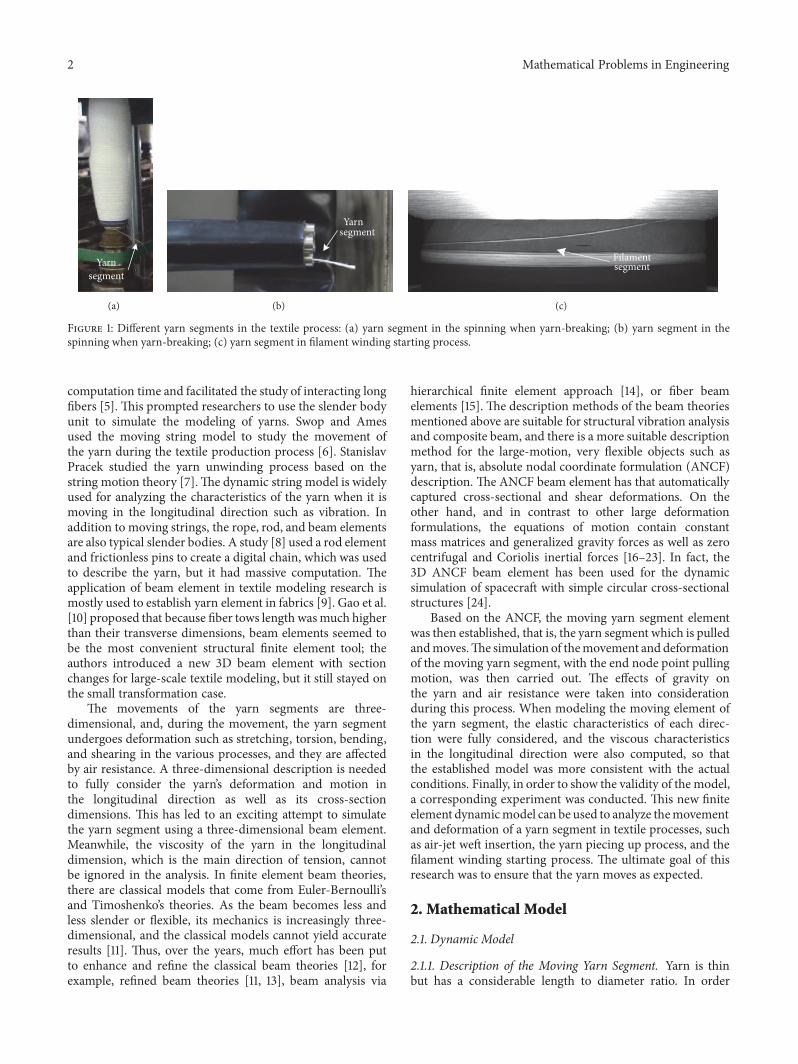
to create a generally described model it was assumed thatthe yarn was an ideal continuum with a circular cross-section as shown in Figure 2 Based on this assumption allkinds of yarns are can be described with their diameter andlength parameters It should be noted that the cross-sectionaldiameter and the length of the yarn are the equivalentparameters used for the mathematical model of the movingyarn segment These equivalent parameters can be obtainedby experimental methods or calculated using the followingphysical parameters the linear density of the yarn the twistper unit length and the parameters of the fiber materialFigure 2 shows the simplified model of the moving yarnsegment in the textile industry process
In this section the theoretical model of the movingyarn segment has been established based on the ANCF [16]starting with the element model of the moving yarn segment
212 Element Model In this section the three-dimensionalelement of a moving yarn segment has been proposed basedon the ANCF [16] The element has been described in theglobal co-ordinate frameOXYZ Each element has two nodesas shown in Figure 3
As shown in Figure 3 the element of the moving yarnsegment has an ideal circular cross-section The axial lengthof the element is l푒 and points A and B represent the nodesof the element The local element spatial coordinates oxyzwere established using node A as the origin x is the tangentalong the longitudinal axis of the element and y and z weredefined in the transverse directions The displacement andslope were employed as the nodal coordinates of an elementso the nonvector rotational parameters could be avoidedThere were 12 coordinate components of each node and 24components of the element using the ANCF which can bewritten as
e = rT퐴 rT퐴푥 rT퐴푦 rT퐴푧 rT퐵 rT퐵푥 rT퐵푦 rT퐵푧T (1)
where r퐴 and r퐵 are the global position vectors of nodes Aand B there are three global position components in eachnode respectively and r퐴푎 and r퐵푎 are the position vectorgradients 119886 = 119909 119910 119911 defined as r퐴푎 = 120597r퐴120597119886 and r퐵푎 =120597r퐵120597119886 The global position vector r of the arbitrary point
P at the moment t can be obtained from the coordinatee
r (119909119910 119911 119905) = S (119909119910 119911) e (119905) (2)
where S is the global element shape function matrix
S = [1198781I 1198782I 1198783I 1198784I 1198785I 1198786I 1198787I 1198788I] (3)
where I is 3times3 identity matrix and 119878푖 = 119878(120585 120578 120577) and its valuescan be obtained by local coordinates x y z and defined as
1198781 = 1 minus 31205852 + 212058531198782 = 119897푒 (120585 minus 21205852 + 1205853)1198783 = 119897푒 (120578 minus 120585120578)1198784 = 119897푒 (120577 minus 120585120577)1198785 = 31205852 minus 212058531198786 = 119897푒 (21205852 + 1205853)1198787 = 119897푒1205851205781198788 = 119897푒120585120577
(4)
The nondimensional quantities 120585 120578 120577 are defined as
120585 = 119909119897푒120578 = 119910119897푒120577 = 119911119897푒
(5)
and 119897푒 is the length of the yarn beam element in theundeformed configuration (straight configuration also seeFigure 4)
Since the cross-section of the element of the movingyarn segment is assumed to be circular for the convenienceof calculation the following coordinate transformation canbe performed as shown in Figure 3 Therefore the globalelement shape function matrix S(119909119910 119911) and be transformedinto S(119909119903 120579)
119910 = 119903 cos 120579119911 = 119903 sin 120579119909 isin [0 119897푒] 119903 isin [0 1198892 ] 120579 isin [minus120587 120587]
(6)
where d is the equivalent diameter of the cross-section of theyarn segment The generalized mass matrix of the movingyarn segment element in the ANCF is a constant matrix [25]
M = int푉
120588푦푎푟푛STS ∙ d119881 (7)
where 120588푦푎푟푛 is the linear mass density of the yarn
4 Mathematical Problems in Engineering
x
Y
Z
O
r
X
y
zo
Yarn center line
Yarn cross section
AB
Yarn cross-section
o
z
y
r
le
rB
Figure 3 The moving yarn segment element model
Yarn element configuration J
r
V
Z(z)
X
Y(y)X(x)
Current deformed Configuration
Undeformed configuration
O(o)
A2
A1
V1
B2
B1
le
Figure 4 Configurations of moving yarn
213 Kinematics and Deformation Based on continuummechanics there are two kinds of configurations that are usedto describe the deformation and motion of the moving yarnsegment as shown in Figure 4
The two configurations can be defined in the globalcoordinate system 119874119883119884119885 which are called the undeformedconfiguration and the current deformed configuration Theundeformed configuration describes the moving yarn seg-ment element which is in a straight condition as well as areference object Its local coordinate system 119900119909119910119911 coincideswith the global coordinate system 119874119883119884119885 and the volumeof the element is 119881 After a period of time the moving yarnsegment will move and deform and the element will be in thecurrent deformed configuration the coordinates of the yarnelement in the current configuration is expressed as r and itsvolume as 1198811
The kinetic energy of a yarn element can be defined as
T = 12 intv 120588푦푎푟푛 rT r ∙ dv =12 eTMe (8)
where 120588푦푎푟푛 is the density of the yarn
214 Strain Energy Theelement of themoving yarn segmentwill move and change from one configuration to anotherwhich can be described by the Jacobian matrix 119869 which is acoordinate transformation matrix [16] Based on the Green-Lagrange strain and the second Piola-Kirchhoff tensor theyarnrsquos Green-Lagrange strain tensor 120576 can be expressed as
120576 = [[[
12057611 12057612 1205761312057622 12057623
119904119910119898 12057633]]]= 12 (JTJ minus I) (9)
As the strain tensor is symmetric six independent straincomponents can be identified that can be used to define thestrain vector as
120576v = [12057611 12057622 12057633 12057612 12057613 12057623]T (10)
where 120576푖푗 for 119894 = 119895 are called normal strains and 120576푖푗 for 119894 = 119895are called shear strains
Mathematical Problems in Engineering 5
The stored strain energy density function in the elementcan be written as
U (120576e + 120576vis) = Ue +Dvis (11)
where U푒 denotes the elastic energy and DV푖푠 denotes theenergy dissipated
215 Generalized Elastic Forces The elastic energy of theyarn element U푒 can be written as
Ue = 12 intv (Ctr120576v)T E (Ctr120576v) ∙ dv (12)
where E is the fourth-order tensor of the matrix of the elasticcoefficient that will be introduced in the following sectionthe constitutive equation of yarn C푡푟 is a constant coefficientmatrix and can be defined as follows
C푡푟 = [I 00 2I
] (13)
The elastic forces can be obtained as gradients of theelastic energy U푒
Qe = 120597Ue120597e= int
v[12059712057611120597e
12059712057622120597e12059712057633120597e 212059712057612120597e 212059712057613120597e 212059712057623120597e ] ∙ E
∙ [12057611 12057622 12057633 212057612 212057613 212057623]T dv(14)
216 Generalized Viscos Force The dissipated energy due toviscosity can be written as
Dvis = 12 intv 120578vis (vis)2 dv (15)
where 120578vis is the viscosity coefficient of the yarn element and120576vis is the viscous strain rate 120576V푖푠 is the viscous strain whichis governed by the following equations
V푖푠 + 1120591120576V푖푠 =1120591120576 (16)
where 120591 is called the relaxation time 120591 = 120578vis119864L and where119864L is the tensile elastic modulus in the longitudinal directionThe generalized viscosity force can then be written as
Qvis = 120597Dvis120597e (17)
217 Generalized Gravity When the yarn is moving in theprocessing space the yarn is subjected to the force dueto gravity If the principle of conservation of mass or thecontinuity condition is assumed the virtual work of theinertial force can be written as
Wi = intv1120588yarnaT120575rdv1 (18)
Yarn centerline
t
n
b
v
P
>Qr
Figure 5 Air resistance of the moving yarn
where v1 is the volume of the yarn in the current configu-ration v1 = |J| sdot dV 120588푦푎푟푛 is the density of the yarn and ais the vector due to gravitational acceleration in the globalcoordinate system If the gravitational acceleration in thedirection of -Z is defined then the vector a can be writtenas a=[0 0 minus 119892]T where 119892 is the acceleration due to gravity
From formula (18) the generalized gravity force formulacan be obtained and written as
Qg = 120575Wi120575e (19)
218 Air Resistance Forces Apart from the body forces theyarn is subject to surface forces such as air resistance whichplays a vital role during the movement of the yarn Figure 5shows a side view of a yarn that is subject to air resistance
The vectors b n t and are three sets of mutually perpen-dicular vectors t is the tangent to the centerline of the yarnat point P n is perpendicular to the centerline and b is thebinormal vector The three vectors have the relationship
b = 119903耠 times 119903耠耠1003817100381710038171003817119903耠 times 119903耠耠1003817100381710038171003817 (20)
n = b times t = (1199031015840 times 11990310158401015840) times 119903101584010038171003817100381710038171199031015840 times 119903101584010158401003817100381710038171003817 ∙ 100381710038171003817100381711990310158401003817100381710038171003817 (21)
When the yarn is moving with a given velocity v the airresistance force is acting against v in accordance with theformula
dQr = 12119862r120588airdAcos120573 k k (22)
where119862r = 034 which is the drag coefficient of a streamlinedbody [26] 120588air is the density of the air dA cos 120573 is the effectivearea of the cross section of yarn 120573 is the angle between thevectors v and n
The exact formula of the air resistance of the yarn elementcan be written as
Qr = intV
12119862r120588airdA cos 120573 k kdV (23)
219 Dynamics Equations Under the action of gravity Q푔the elastic force Q푒 and the generalized viscosity force due
6 Mathematical Problems in Engineering
to deformation and the air resistance force Q푟 the dynamicsequation of the yarn can be expressed by the generalized forceas
Me (119909 119910 119911 119905) +Qe +Qvis = Qg + Qr (24)
22 Constitutive Equation In this section the constitutivemodel of the yarn has been discussed The yarn which isthe fiber assembly has a special structure in comparison totraditional materials In the existing research and dependingon the state of the yarn there have been different descriptionsof the yarn pure elasticity viscosity and viscoelasticity Forinstance when discussing the coupling of the fiber andthe airflow [27ndash29] especially during vortex spinning thefibers or yarns were considered as a pure elastic body ineither one or two dimensions When analyzing the vibrationperformance of the moving yarn it was treated as a one-dimensional viscoelastic body [30] These studies ignoredthe coupling between stretching shearing and torsion ofthe yarn which resulted in an inaccurate description ofthe yarn and produced large deformation and a wide rangeof movement When the yarn was moving it displayedelasticity while also exhibiting some viscosity Therefore inorder to ensure that the elastic characteristics of the yarnare fully described in all directions and at the same timethat the viscoelastic characteristics are also described in thelongitudinal direction that is the main direction in whichthe yarn is subjected to tension during the manufacturingprocess and the followingmethod has beenused in this paperto calculate the constitutive relationship of the yarn
Therefore the total strain energy of the yarn consists oftwo parts the first is the elastic strain energy and the secondis the dissipation energy Correspondingly the stress can bewritten as
120590 = 120590e + 120590vis (25)
where 120590e denotes the elastic force and 120590vis represents theviscosity forceThe strain and stress of the yarn can be linkedusing the constitutive relation In the past 30 years manyscholars have studied the equivalent constitutive relation ofyarn [17 31 32] In order to simplify the description as wellas the modeling of the yarn it can also be considered as amaterial that does not possess structural parameters ignoringthe effects between single fibers in the yarn Since the yarn canbe considered as isotropic and symmetrical in cross-sectiontransversely isotropic elastomers can be used to describe theelastic performance of the yarn The relationship betweenstress and strain can be written as follows
120576exx120576eyy120576ezz120576ely120576ezl120576eyz
= C
120590ex120590ey120590ez120590exy120590ezx120590eyz
(26)
where 120576eij 119894 119895 = 119909 119910 119911 denote the axial and shear Green-Lagrange strains andC is thematrix of the elastic coefficients
When a yarn is defined as having square-symmetric andtransversely isotropic homogeneous continuum the elasticcompliance matrix can be expressed by the modulus andPoissonrsquos ratios [33]
C =
[[[[[[[[[[[[[[[[[[[
1119864퐿 minusV푇퐿119864푇 minusV푇퐿119864푇 0 0 0minusV퐿푇119864퐿
1119864푇 minusV푇푇119864푇 0 0 0
minusV퐿푇119864퐿 minusV푇푇119864푇1119864푇 0 0 0
0 0 0 1119866푇퐿 0 0
0 0 0 0 1119866푇퐿 00 0 0 0 0 1
119866푇푇
]]]]]]]]]]]]]]]]]]]
(27)
where 119864퐿 is the longitudinal elastic modulus governing theuniaxial loading in the longitudinal direction (along the119909 axis of the yarn) V퐿푇 is the associated Poissonrsquos ratiothat accounts for the effect of the strains in the transversedirections 119864푇 is the transverse elastic modulus (in the cross-section 119910 or 119911 direction) V푇푇 is the associated Poissonrsquos ratiogoverning the resultant strains in the remaining orthogonaltransverse directions (119910 or 119911 direction) V푇퐿 is correspondingPoissonrsquos ratio governing the induced strain in the longitu-dinal direction 119866푇퐿 is the shear modulus governing shearin the longitudinal direction and 119866푇푇 is the shear modulusgoverning shear in the transverse plane
In the case of transverse isotropy 119866푇푇 is a dependentmodulus which is equal to 119866푇푇 = 119864푇2(1 + V푇푇) and 119866푇퐿 =119864푇2(1 + V푇퐿)
The yarn also exhibits viscosity during large deformationandmovement In particular the yarn has a damping effect ofthe nonnegligible viscous force in the longitudinal directiondue to its tension Moreover since the yarn has a sizeabletensile modulus in the longitudinal direction it also exhibitsa particular form of oscillation during movement whichfurther indicates that the energy dissipated by the viscousforce in the longitudinal direction cannot be ignored Whenconsidering the viscosity of the yarn in the longitudinaldirection the stress-strain relationship can be written asfollows
120590vis = 120578vis d120576푥푥d119905 (28)
where 120578vis is usually measured through static testing andd120576푥푥d119905 is the strain rate of the yarn in the longitudinaldirection This strain is the same as the strain in the longi-tudinal direction when calculating the elastic strain energyThis also indicates that the description of the viscoelasticityand elasticity in the longitudinal direction are interrelated
23 Solution Procedure In this study the governing equationfor the yarn segment motion Equation (24) is solved using theODE45 method to obtain the global position vectors of eachnode The solution procedure which is shown in Figure 6 isas follows
Mathematical Problems in Engineering 7
Input initial parametersConstraints and velocity conditionsGeometry and material conditionsOriginal unit size and unit numberInitial generalized position and VelocitySimulation time
Calculate the generalized mass matrix generalizedgravity generalized air resistance generalized elasticforce and viscos forceSet the velocity of the pulling on the end-point of the yarnsegment
Numerical integration
Update simulation timeobtain the new position vector
and velocity vector
Simulation time
End of simulation
Within theSimulation tiem
Simulationloop
(x y z t) + + PCM = A + L
Figure 6 Solution procedure
(1) Set the calculation parameters including simulationtime Set the geometrical and physical parameters of the yarnsegment(2) Set the initial configuration of the yarn segmentincluding the generalized initial position and generalizedinitial velocity of the yarn segment(3) Set the element number of the model(4) Set the velocity of one endpoint of the yarn segmentwhich is the yarn guiderrsquos velocity(5)Calculate the generalizedmassmatrix and generalizedelastic force viscos force gravity and air resistance force(6) Solve the governing equations for the yarn segmentmotion to obtain the new position vector and velocity vector(7) Return to step (4) and repeat the procedure until theend of the computation is reached
3 Experimental Validation
31 Motions of Pulling the Yarn Segment in the Air In thissection the results of the simulation and the experiments
with a moving yarn segment have been presentedThe resultshave been shown here to demonstrate the effectiveness ofthe proposed moving yarn segment model For this reasona polyester filament bundle which is the most basic typeof the yarn was used as the object for the simulations andexperiments As the cross-section of the polyester monofila-ment is circular and the bundle of filaments is approximatelyparallel when arranged in the straightened state this is morein line with the assumption that was made for the constitutiverelationship
311e Initial Configuration andMovement Figure 7 showsthe initial position that was assumed before the simulationwas carried out The traction fixer held the endpoint ofthe filament bundle For the specific clamping method seethe section described in ldquoClamping Moderdquo and the otherendpoint was clamped in the same way The initial filamentbundle remained horizontal but the tension was nearly zerowhich was ensured using the precision tension measuringinstrument At the beginning of the experiment the traction
8 Mathematical Problems in Engineering
l
X
Z
Y
Traction fixer Slide way
v
Yarn
Initial configuration
Moving process
Figure 7 Moving yarn model for simulation and experiment
Filamentbundle
Figure 8 Clamped filament bundle
fixer propelled the end of the yarn and moved it at a constantspeed while the constraint at the other end was releasedand the filament bundle was pulled down by gravity Thetrajectory of the filament bundle was recorded using a high-speed camera
312 Clamping Mode Firstly the clamped end of the fila-ment bundle was fixed with a porcelain eye that is commonlyused to guide yarns in the process The porcelain eye is aceramic workpiece with a diameter of 05mm as shown inFigure 8 so that the cross-section of the restrained end ofthe filament bundle is guaranteed to be a circle The filamentbundle is wetted by an oil agent so that the monofilaments aretightly held together and the middle section of the filamentbundle can also be considered to be approximately circularThe filament bundle is fixed to the porcelain eye by stickyglue In order to ensure that the yarn was not contaminatedby the glue the fixed section of the filament bundle and theporcelain eye were not included in the sample that was usedin the experiment The porcelain eye was mounted on theclamping plate with the traction fixer as shown in Figure 8
313 Traction Speed and Total Stroke The purpose of thesimulation and the experiment was to verify the accuracyof the moving yarn segment model Since the length of thesimulated filament bundle was 032mm in order to observethe trajectory of the movement more clearly it needed tobe moved at least 13 of its length during the experiment
Table 1 The parameters of the filament bundle used in simulationand experiment
Parameter Value and unitThe density of the polyester material 1320 kgm3
Linear mass density (measured value) 6142 texTensile modulus 103 times 108 Nm2Viscosity coefficient 37 times 108 Nsdotsm2Fiber volume fraction 7016Length 320mmCross section diameter 092 mmAir density 12 kgm3
Combined with the simulation time and the data storecapacity of the high-speed camera the speed of the tractionmotion was determined to be 01 ms according to the strokelength
314 Determination of Physical Parameters The POY fil-ament bundle had a nominal denier of 220dtex72f Forbetter observation 24 bundles of these POY filaments werecombined into a bundle Therefore the actual linear massdensity of the filament bundle was 5280dtex A precisionlength measuring instrument (YG086) used to measure thelength of the sample which was 320mm According to theproduct manual the density of the polyester was 138 gm3Before the experiment the actual linear mass density of thefilament bundle was measured using a precision balance(PRACTUM2102-1CN) according to the standard methodof testing linear mass density [34] The actual diameter ofthe filament bundle was measured using scanning electronmicroscopy (JCM-6000PLUS)
315 Determination of Constitutive Parameters The tensilemodulus of the filament bundle was measured using alarge-scale single yarn strength gauge (SITHAI ST-D100)According to the assumed idealized conditions the shearmodulus and Poissonrsquos ratio were determined using equation= 1198642(1 + ])
The modulus and Poissonrsquos ratio in the other directionscould be determined using the method in the literature [33]The viscosity coefficient used the parameters that were foundin the literature [30] Table 1 lists the parameters of the
Mathematical Problems in Engineering 9
high-speed camera
traction fixer The filament bundle
Control system
i
ii iii
Computer for high-speed camera
high-power lighting
traction fixer control computer
Initial configuration
(a)
1
24
5
6
7
3
(b)
Figure 9 Moving yarn model for simulation and experiment (a) schematic diagram and (b) test site (1) Traction fixer control computer(2) traction fixer (3) computer for high-speed camera (4) the filament bundle (5) high-speed camera (6) high-power lighting (7) controlsystem
filament bundle that were used in the simulation Figures 9(a)and 9(b) show the experiment schematic diagram and test sitepicture
32 Results When the traction fixer which clamped theendpoint of the filament bundle began to move the otherendpoint was released A high-speed camera recorded themoving trace of the filament bundle which was used tovalidate the model of the yarn The motion states of thefilament bundle at 005 01 and 06 s were shown in Figures10(a)ndash10(c) The comparison of the results has been shown inFigure 10(d)
The filament bundle moved under the pulling action ofthe fixer Figures 10 have shown that the positions of the fila-ment bundle for the different times that were obtained fromthe simulation and the experimental test were very similar
The moving trace of the filament bundle at 06s was almostthe same but they diverged at 025 s especially in the middlesection The experimental results showed a more curvedresult than that from the simulated resultsThe reasons for thedifference were most likely as follows (a) the motion of thefilament bundle was affected by the air resistance Thus theappropriate air resistance coefficient should be incorporatedinto the simulation The simulation in this paper used theresults from the literature [26] (b) The viscoelasticity of thefilament bundle has a very significant effect on the resultsThe simulation in this paper only considered the viscosity inthe longitudinal direction which is a reasonable and efficientassumption when the moving yarn segment is subjectedto high tension Otherwise the three-dimensional viscos-ity should be taken into consideration during the model-ing
10 Mathematical Problems in Engineering
0
minus005
minus01
minus015
minus02
minus025
minus03
0 005 01 015 02 025 03 035 04
(a)
0
minus005
minus01
minus015
minus02
minus025
minus03
0 005 01 015 02 025 03 035
(b)
0450 005 01 015 02 025 03 035 04
0
minus005
minus01
minus015
minus02
minus025
minus03
minus035
(c)
minus0
050
000
050
100
150
200
250
300
350
400
45
t=0 simulationt=0 experimentt=005simulationt=005experimentt=01simulationt=01experiment
t=0255simulationt=0255experimentt=045 simulationt=045experimentt=06 simulationt=06experiment
minus035minus030minus025minus020minus015
minus005000005010
minus010
Z di
rect
ion
X direction
(d)
Figure 10 Experimental validation (a) Motion comparison at 005s (b) Motion comparison of 01s (c) Motion comparison of 06s (d)Experimental and simulation comparison
Mathematical Problems in Engineering 11
Twisted zoneYarnguide hook
Bobbin
Twisting rollers
Figure 11 Yarn spinning process
Yarn segment
Yarn gripper
Robot arm
Automatic yarn jointing
robot
Figure 12 Automatic yarn-jointing robot
4 Motion of the Yarn Segment during theAutomatic Yarn Piecing Process
Automatic yarn piecing technology is the key technologyneeded to realize the intelligent spinning process The devel-opment of an automatic piecing robotwould play a significantrole in enhancing the yarn spinning efficiency and guarantee-ing the spinning quality Already relatively mature automaticpiecing devices have been developed such as the FIL-A-MATautomatic piecing device (based on the Zinser 320 spinningmachine) Fiasol automatic piecing device (Came Italy)Heathpan automatic piecing device AYPT type automaticpiecing device and ROBOFIL automatic piecing deviceand these devices can usually complete the detecting andpiecing up process in less than 30 seconds While developingautomatic piecing technology the design and control ofthe yarn piecing up module are major concerns The yarnsegment is pulled through the yarn guide hook and fed intothe twist zone during this process Finding the best methodto complete the yarn piecing action quickly and accurately isthe primary issue
Taking the working process of the automatic yarn piecingrobot during ring spinning as an example the automaticpiecing up work is performed by a robot arm Figure 11presents a schematic view of the ring spinning process Therobot armmust pull the yarn segment (Figure 12) to completea series of actions such as winding it onto the bobbin passing
Table 2 The parameters of the cotton yarn used in the simulation
Parameter Value and unitThe density of the cotton yarn 15 times 1031198961198921198983Linear mass density (measured value) 3242 texTensile modulus 243 times 108 Nm2Viscosity coefficient 152 times 108 Nsdotsm2Fiber volume fraction 6955Length 320mmCross section diameter 066 mmAir density 12 kgm3
it through the yarn guide hook and feeding it into the twistingrollers as shown in Figure 13 Whether the yarn segment cancomplete the actions mentioned above under the guidance ofthe robot armwill determine the results of the automatic yarnpiecing Thus predicting the trajectory of the yarn segmentfor different pulling speeds can be used to design and controlthemotionplanning of the robot armThe simulation focusedon the process of the cotton yarn segment passing through theyarn guide hook to determine whether the designed velocityof the robot arm is suitable for pulling the yarn segmentthrough the guide hook Table 2 lists the parameters of thecotton yarn used in this simulation The simulation results(Figure 14) showed the trajectory of the yarn segment beingpulled by the robot arm gripper which is under the designedvelocity parameters as shown in Table 3
As shown in Table 2 the endpoint of the yarn segmentwas pulled by the robot arm at different velocities duringthe spatial motion The simulation produced the trajectoryof the yarn segment in the different positions as shown inFigure 14 The yarn segment was gripped by the robot armand first moved toward the yarn guide hook The velocitiesin the Y and Z directions were both 15 ms To prevent theaccidental occurrence of friction between the yarn segmentand the guide hook support arm after moving at the above-mentioned speed for 008 s the robot arm changed thevelocity and the direction of movement and pulled the yarnsegment to move in the direction of the opening of the guidehookAfter the yarn segment had passed through the openingof the yarn guide hook the robot arm changed the directionand velocity of the movement again and the yarn beingmoved in the opposite direction to the opening of the yarnguiding hook to ensure that the yarn segment was alreadyinside the yarn guide hook Figure 14(a) shows that whenthe robot arm gripper moved with the designed velocity theyarn segment could move from the horizontal position to thecenter of the guide hook and did not come into contact withthe support arm of the guide hook which is a requirementof the automatic yarn piecing up process In Figure 14 yarnsof different colors represent the trajectories of different yarnsegments and the three parts of Figures 14(b)ndash14(d) describethe change in the trajectory of yarn segments when they weremoved at the three velocities mentioned above as shown inTable 3
The case described above has shown that the model thathas been introduced in this paper can predict the trajectory
12 Mathematical Problems in Engineering
Table 3 The velocity of the robot arm (which gripped the endpoint of the yarn)
Position statement of the yarnsegment
Velocity in the Ydirection (ms)
Velocity in the Zdirection (ms)
Simulation time movingtime (s)
Correspondingconfiguration in
Figure 14Straight position to position 1 15 15 008 (b)Position 1 to position 2 -4 1 005 (c)Position 2 to position 3 -2 -04 005 (d)
Robot armgripper
Yarn segment
Bobbin
(a)
Yarn segment
Yarnguide hook
Robot armgripper
(b)
Yarn segment
Twisting rollers
(c)
Figure 13 Yarn segment motion during the piecing up process by the robot arm (a) Winding on the bobbin (b) Passing through the yarnguide hook (c) Feeding into the twisting rollers
of the yarn segment under different pulling motions fromthe robot arm On the basis of this model and by modifyingits boundary conditions or expanding the coupling conditionof the yarn with the mechanical parts it is now possible topredict other movement behaviors of the yarn segment of theautomatic piecing process such as winding the yarn onto thebobbin and feeding into the twisting zone
5 Conclusions
This paper has proposed a dynamic model of a yarn segmentto predict the yarnrsquos motion trajectory based on the ANCFWhen establishing the moving yarn segment model theelasticity in the longitudinal direction and cross-sectiondirections were considered as well as the viscosity charac-teristic in the longitudinal direction In order to enable themodel to analyse the moving yarn segments for the actualprocesses the effect of both air resistance and gravity weretaken into consideration during the creation of the model
As an example used to verify the simulation of the modela model of the filament bundle where the gripper pulled itfrom one end on the guideway has been implemented thispaper The simulation and the corresponding experimentverified the accuracy of the model Apart from this andin order to better understand how to use the model topredict the motion process of the moving yarn segmentanother simulation was implemented which described themovement of the cotton yarn when it was pulled at different
velocities during the automatic yarn piecing up processThis simulation described the yarn segment pulled from thehorizontal position to the centre of the yarn guide hookDuring this process the yarn segment could not contact thesupport arm of the yarn guide hook Thus it was possibleto check whether the designed velocity of the robot armsatisfies the requirements by observing the trajectory of theyarn segment
On this basis thismodel can be used effectively to providea reference for the analysis of yarn segmentmotionduring thetextile process by extending themodelwith specific boundaryconditions and constraints Compared with modeling theyarn as either a moving string or a pure elastic body themodel that has been established in this paper is able tomore effectively simulate the actual moving trace of the yarnsegment when it is being pulled in the processes such as theyarn segment protruding from the nozzle during air-jet weftinsertion and the filament bundle segment during the startof the winding process Through the use of the equations inthis model it is also possible to calculate the distribution ofthe tension in the yarn segment during movement This haslaid the groundwork for the establishment of a multibodysystem model for the coupling of the moving yarn segmentwith the mechanical part For example in order to simulatethe dynamic behaviour of the yarn segment coupled tothe gripper of the automatic yarn-jointing robot when inoperation Outlines for further research have been proposedas follows
Mathematical Problems in Engineering 13
Spatial configuration X-Y plane
02
00
z
y
x
minus015
minus010
minus005
000
005
010
015
minus05
000
005
010
015
020
025
030
035
minus05
000
005
010
015
020
025
030
035
x
015010005
y000
minus005minus010minus015
(a)
X-Y plane X-Z planeSpatial configuration Y-Z plane
z
02
01
00
minus05
000
005
010
015
020
025
030
035x
z
02
01
00
minus01 014012010008006 y004002000minus002
x
y
minus05
000
005
010
015
020
025
030
035
014
012
010
008
006
004
002
000
minus002
(b)
X-Y plane X-Z planeSpatial configuration Y-Z plane
005
010
015
020
025
x
minus015
minus010
minus005
000
005
010
015
y z014
012
010
008
006
004
002
000
018
016
z
014012010008006004002000
minus002
018016
000
005
010
015
020
025x
015010005
y000minus005minus010minus015
(c)
X-Y plane X-Z planeSpatial configuration Y-Z plane
000
005
010
015
020
025
x
minus005
000
005
010
015
y
z
014
012
010
008
006
004
002
000
minus002
018
016
z
014012010008006004002000
minus002
018016
000
005
010
015
020
025x
015010005
y000minus005
(d)
Figure 14 The spatial motion of the yarn segment under the pulling of robot arm (a) The process of passing through the yarn guide hook(b)The first position of the yarn segment (c) The second position of the yarn segment (d) The third position of the yarn segment
(1) Accurate parameter identification is vital when deal-ing with themodeling of a specific yarn Furthermorethe actual state of the yarn during the productionprocess should be taken into consideration such as its
tension and temperature when determining the yarnrsquosparameters
(2) It is of interest to try to account for the viscosity of thecross-section dimension of the yarn as well as using
14 Mathematical Problems in Engineering
the three-dimension viscoelastic model to describethe constitutive relationship of the yarn Howeverthere is no doubt that this will also increase theamount of calculation inherent in the model
Data Availability
The data used to support the findings of this study areavailable from the corresponding author upon request
Conflicts of Interest
The authors declare no conflicts of interest
Acknowledgments
This work was supported by the National Key RampD Programof China (2017YFB1304000) Natural Science Foundation ofShanghai (16ZR1401900) and Applied Foundation Researchof China National Textile and Apparel Council (J201504)
References
[1] Y Zeng and C Yu ldquoA bead-elastic rod model for dynamicsimulation of fibers in high speed air flowrdquo International Journalof Nonlinear Sciences andNumerical Simulation vol 4 no 2 pp201-202 2003
[2] Y Zeng andC Yu ldquoNumerical simulation of fibermotion in thenozzle of an air-jet spinning machinerdquoTextile Research Journalvol 74 no 2 pp 117ndash122 2016
[3] P Skjetne R F Ross and D J Klingenberg ldquoSimulation ofsingle fiber dynamicsrdquoe Journal of Chemical Physics vol 107no 6 pp 2108ndash2121 1997
[4] S Yamamoto and T Matsuoka ldquoA method for dynamic simu-lation of rigid and flexible fibers in a flow fieldrdquo e Journal ofChemical Physics vol 98 no 1 pp 644ndash650 1993
[5] R F Ross and D J Klingenberg ldquoDynamic simulation offlexible fibers composed of linked rigid bodiesrdquo e Journal ofChemical Physics vol 106 no 7 pp 2949ndash2960 1997
[6] R D Swope and W F Ames ldquoVibrations of a moving thread-linerdquo Journal of e Franklin Institute vol 275 no 1 pp 36ndash551963
[7] S Pracek ldquoTheory of string motion in the textile process ofyarn unwindingrdquo International Journal of Nonlinear Sciencesand Numerical Simulation vol 8 no 3 pp 451ndash460 2007
[8] G Zhou X Sun and Y Wang ldquoMulti-chain digital elementanalysis in textile mechanicsrdquo Composites Science and Technol-ogy vol 64 no 2 pp 239ndash244 2004
[9] Y Mahadik and S Hallett ldquoFinite element modelling of towgeometry in 3D woven fabricsrdquo Composites Part A AppliedScience and Manufacturing vol 41 no 9 pp 1192ndash1200 2010
[10] S Gao B Liang and E Vidal-Salle ldquoDevelopment of a new 3Dbeam elementwith section changesThe first step for large scaletextile modellingrdquo Finite Elements in Analysis and Design vol104 pp 80ndash88 2015
[11] E Carrera and G Giunta ldquoRefined beam theories based on aunified formulationrdquo International Journal of Applied Mechan-ics vol 2 no 1 pp 117ndash143 2010
[12] A Pagani M Petrolo G Colonna and E Carrera ldquoDynamicresponse of aerospace structures by means of refined beam
theoriesrdquo Aerospace Science and Technology vol 46 pp 360ndash373 2015
[13] A Tessler M Di Sciuva and M Gherlone ldquoA refined zigzagbeam theory for composite and sandwich beamsrdquo Journal ofComposite Materials vol 43 no 9 pp 1051ndash1081 2009
[14] Y Hui G Giunta S Belouettar Q Huang H Hu and E Car-rera ldquoA free vibration analysis of three-dimensional sandwichbeams using hierarchical one-dimensional finite elementsrdquoComposites Part B Engineering vol 110 pp 7ndash19 2017
[15] K Park H Kim and D Kim ldquoGeneralized finite elementformulation of fiber beam elements for distributed plasticityin multiple regionsrdquo Computer-Aided Civil and InfrastructureEngineering vol 34 no 2 pp 146ndash163 2019
[16] R Y Yakoub and A A Shabana ldquoThree dimensional absolutenodal coordinate formulation for beam elements implementa-tion and applicationsrdquo Journal ofMechanical Design vol 123 no4 pp 614ndash621 2001
[17] W Yoo O Dmitrochenko S Park and O Lim ldquoA new thinspatial beam element using the absolute nodal coordinatesapplication to a rotating striprdquo Mechanics Based Design ofStructures and Machines vol 33 no 3-4 pp 399ndash422 2005
[18] P Eberhard and W Schiehlen ldquoComputational dynamics ofmultibody systems history formalisms and applicationsrdquo Jour-nal of Computational and Nonlinear Dynamics vol 1 no 1 pp3ndash12 2006
[19] A A Shabana ldquoAn absolute nodal coordinates formulation forthe large rotation and deformation analysis of flexible bodiesrdquoTechnical Report No MBS96-1-UIC University of IllinoisChicago Ill USA 1996
[20] A Shabana ldquoDefinition of the slopes and absolute nodalcoordinate formulationrdquoMultibody SystemDynamics vol 1 no3 pp 339ndash348 1997
[21] M A Omar and A A Shabana ldquoA two-dimensional sheardeformable beam for large rotation and deformation problemsrdquoJournal of Sound and Vibration vol 243 no 3 pp 565ndash5762001
[22] H Sugiyama and Y Suda ldquoA curved beam element in theanalysis of flexible multi-body systems using the absolutenodal coordinatesrdquo Proceedings of the Institution of MechanicalEngineers Part K Journal of Multi-body Dynamics vol 221 no2 pp 219ndash231 2007
[23] O Dmitrochenko and D Pogorelov ldquoGeneralization of platefinite elements for absolute nodal coordinate formulationrdquoMultibody System Dynamics vol 10 no 1 pp 17ndash43 2003
[24] K Otsuka and K Makihara ldquoAbsolute nodal coordinate beamelement for modeling flexible and deployable aerospace struc-turesrdquo AIAA Journal vol 57 no 3 pp 1343ndash1346 2019
[25] A A Shabana Computational Continuum Mechanics Cam-bridge University Press Cambridge UK 2nd edition 2012
[26] Y Z Liu and Y D Qian ldquoThe experiment of measurement theair drag coefficient of different shape objectsrdquo College Physicsvol 36 no 3 pp 16ndash19 2017
[27] Y Z Jin and J Li ldquoNumerical simulation on coupling of fiberand air flowrdquo Journal of Textile Research vol 36 no 1 pp 153ndash157 2015
[28] S Y Chen Study on We Yarns Instability Behavior duringe Start-Up of We Insertion Zhejiang Sci-Tech UniversityHangzhou Zhejiang China 2015
[29] Z G Pei Study on the Characteristics and Application of theFiber-Airflow Interaction in Vortex Spinning Donghua Univer-sity Shanghai China 2011
Mathematical Problems in Engineering 15
[30] H Lin Dynamical Behavior and Control of Moving YarnsSoochow University Su Zhou Jiang Su China 2014
[31] A Abdel-Nasser A A Mohamed and J Liu ldquoThe threedimensional gradient deficient beam element (BEAM9) usingthe absolute nodal coordinate formulationrdquo in Proceedingsof the ASME 2014 International Design Engineering TechnicalConferences and Computers and Information in EngineeringConference American Society of Mechanical Engineers Buf-falo NY USA 2014
[32] Y Zhang C Wei Y Zhao C Tan and Y Liu ldquoAdaptiveANCFmethod and its application in planar flexible cablesrdquoActaMechanica Sinica vol 34 no 1 pp 199ndash213 2018
[33] L Wang Y Wang A M Recuero and A A Shabana ldquoANCFAnalysis of Textile Systemsrdquo Journal of Computational andNonlinear Dynamics vol 11 no 3 article 031005 pp 1ndash13 2016
[34] GBT 14343-2008 ldquoTesting method for linear density of man-made filament yarns Chinese National Standardsrdquo 2008
Hindawiwwwhindawicom Volume 2018
MathematicsJournal of
Hindawiwwwhindawicom Volume 2018
Mathematical Problems in Engineering
Applied MathematicsJournal of
Hindawiwwwhindawicom Volume 2018
Probability and StatisticsHindawiwwwhindawicom Volume 2018
Journal of
Hindawiwwwhindawicom Volume 2018
Mathematical PhysicsAdvances in
Complex AnalysisJournal of
Hindawiwwwhindawicom Volume 2018
OptimizationJournal of
Hindawiwwwhindawicom Volume 2018
Hindawiwwwhindawicom Volume 2018
Engineering Mathematics
International Journal of
Hindawiwwwhindawicom Volume 2018
Operations ResearchAdvances in
Journal of
Hindawiwwwhindawicom Volume 2018
Function SpacesAbstract and Applied AnalysisHindawiwwwhindawicom Volume 2018
International Journal of Mathematics and Mathematical Sciences
Hindawiwwwhindawicom Volume 2018
Hindawi Publishing Corporation httpwwwhindawicom Volume 2013Hindawiwwwhindawicom
The Scientific World Journal
Volume 2018
Hindawiwwwhindawicom Volume 2018Volume 2018
Numerical AnalysisNumerical AnalysisNumerical AnalysisNumerical AnalysisNumerical AnalysisNumerical AnalysisNumerical AnalysisNumerical AnalysisNumerical AnalysisNumerical AnalysisNumerical AnalysisNumerical AnalysisAdvances inAdvances in Discrete Dynamics in
Nature and SocietyHindawiwwwhindawicom Volume 2018
Hindawiwwwhindawicom
Dierential EquationsInternational Journal of
Volume 2018
Hindawiwwwhindawicom Volume 2018
Decision SciencesAdvances in
Hindawiwwwhindawicom Volume 2018
AnalysisInternational Journal of
Hindawiwwwhindawicom Volume 2018
Stochastic AnalysisInternational Journal of
Submit your manuscripts atwwwhindawicom
2 Mathematical Problems in Engineering
Yarnsegment
(a)
Yarnsegment
(b)
Filamentsegment
(c)
Figure 1 Different yarn segments in the textile process (a) yarn segment in the spinning when yarn-breaking (b) yarn segment in thespinning when yarn-breaking (c) yarn segment in filament winding starting process
computation time and facilitated the study of interacting longfibers [5] This prompted researchers to use the slender bodyunit to simulate the modeling of yarns Swop and Amesused the moving string model to study the movement ofthe yarn during the textile production process [6] StanislavPracek studied the yarn unwinding process based on thestring motion theory [7]The dynamic string model is widelyused for analyzing the characteristics of the yarn when it ismoving in the longitudinal direction such as vibration Inaddition to moving strings the rope rod and beam elementsare also typical slender bodies A study [8] used a rod elementand frictionless pins to create a digital chain which was usedto describe the yarn but it had massive computation Theapplication of beam element in textile modeling research ismostly used to establish yarn element in fabrics [9] Gao et al[10] proposed that because fiber tows length wasmuch higherthan their transverse dimensions beam elements seemed tobe the most convenient structural finite element tool theauthors introduced a new 3D beam element with sectionchanges for large-scale textile modeling but it still stayed onthe small transformation case
The movements of the yarn segments are three-dimensional and during the movement the yarn segmentundergoes deformation such as stretching torsion bendingand shearing in the various processes and they are affectedby air resistance A three-dimensional description is neededto fully consider the yarnrsquos deformation and motion inthe longitudinal direction as well as its cross-sectiondimensions This has led to an exciting attempt to simulatethe yarn segment using a three-dimensional beam elementMeanwhile the viscosity of the yarn in the longitudinaldimension which is the main direction of tension cannotbe ignored in the analysis In finite element beam theoriesthere are classical models that come from Euler-Bernoullirsquosand Timoshenkorsquos theories As the beam becomes less andless slender or flexible its mechanics is increasingly three-dimensional and the classical models cannot yield accurateresults [11] Thus over the years much effort has been putto enhance and refine the classical beam theories [12] forexample refined beam theories [11 13] beam analysis via
hierarchical finite element approach [14] or fiber beamelements [15] The description methods of the beam theoriesmentioned above are suitable for structural vibration analysisand composite beam and there is a more suitable descriptionmethod for the large-motion very flexible objects such asyarn that is absolute nodal coordinate formulation (ANCF)description The ANCF beam element has that automaticallycaptured cross-sectional and shear deformations On theother hand and in contrast to other large deformationformulations the equations of motion contain constantmass matrices and generalized gravity forces as well as zerocentrifugal and Coriolis inertial forces [16ndash23] In fact the3D ANCF beam element has been used for the dynamicsimulation of spacecraft with simple circular cross-sectionalstructures [24]
Based on the ANCF the moving yarn segment elementwas then established that is the yarn segment which is pulledandmovesThe simulation of themovement and deformationof the moving yarn segment with the end node point pullingmotion was then carried out The effects of gravity onthe yarn and air resistance were taken into considerationduring this process When modeling the moving element ofthe yarn segment the elastic characteristics of each direc-tion were fully considered and the viscous characteristicsin the longitudinal direction were also computed so thatthe established model was more consistent with the actualconditions Finally in order to show the validity of the modela corresponding experiment was conducted This new finiteelement dynamicmodel can be used to analyze themovementand deformation of a yarn segment in textile processes suchas air-jet weft insertion the yarn piecing up process and thefilament winding starting process The ultimate goal of thisresearch was to ensure that the yarn moves as expected
2 Mathematical Model
21 Dynamic Model
211 Description of the Moving Yarn Segment Yarn is thinbut has a considerable length to diameter ratio In order
Mathematical Problems in Engineering 3
Moving yarn segment
Gripper of the machine part v
Circular cross section
Figure 2The moving yarn segment
to create a generally described model it was assumed thatthe yarn was an ideal continuum with a circular cross-section as shown in Figure 2 Based on this assumption allkinds of yarns are can be described with their diameter andlength parameters It should be noted that the cross-sectionaldiameter and the length of the yarn are the equivalentparameters used for the mathematical model of the movingyarn segment These equivalent parameters can be obtainedby experimental methods or calculated using the followingphysical parameters the linear density of the yarn the twistper unit length and the parameters of the fiber materialFigure 2 shows the simplified model of the moving yarnsegment in the textile industry process
In this section the theoretical model of the movingyarn segment has been established based on the ANCF [16]starting with the element model of the moving yarn segment
212 Element Model In this section the three-dimensionalelement of a moving yarn segment has been proposed basedon the ANCF [16] The element has been described in theglobal co-ordinate frameOXYZ Each element has two nodesas shown in Figure 3
As shown in Figure 3 the element of the moving yarnsegment has an ideal circular cross-section The axial lengthof the element is l푒 and points A and B represent the nodesof the element The local element spatial coordinates oxyzwere established using node A as the origin x is the tangentalong the longitudinal axis of the element and y and z weredefined in the transverse directions The displacement andslope were employed as the nodal coordinates of an elementso the nonvector rotational parameters could be avoidedThere were 12 coordinate components of each node and 24components of the element using the ANCF which can bewritten as
e = rT퐴 rT퐴푥 rT퐴푦 rT퐴푧 rT퐵 rT퐵푥 rT퐵푦 rT퐵푧T (1)
where r퐴 and r퐵 are the global position vectors of nodes Aand B there are three global position components in eachnode respectively and r퐴푎 and r퐵푎 are the position vectorgradients 119886 = 119909 119910 119911 defined as r퐴푎 = 120597r퐴120597119886 and r퐵푎 =120597r퐵120597119886 The global position vector r of the arbitrary point
P at the moment t can be obtained from the coordinatee
r (119909119910 119911 119905) = S (119909119910 119911) e (119905) (2)
where S is the global element shape function matrix
S = [1198781I 1198782I 1198783I 1198784I 1198785I 1198786I 1198787I 1198788I] (3)
where I is 3times3 identity matrix and 119878푖 = 119878(120585 120578 120577) and its valuescan be obtained by local coordinates x y z and defined as
1198781 = 1 minus 31205852 + 212058531198782 = 119897푒 (120585 minus 21205852 + 1205853)1198783 = 119897푒 (120578 minus 120585120578)1198784 = 119897푒 (120577 minus 120585120577)1198785 = 31205852 minus 212058531198786 = 119897푒 (21205852 + 1205853)1198787 = 119897푒1205851205781198788 = 119897푒120585120577
(4)
The nondimensional quantities 120585 120578 120577 are defined as
120585 = 119909119897푒120578 = 119910119897푒120577 = 119911119897푒
(5)
and 119897푒 is the length of the yarn beam element in theundeformed configuration (straight configuration also seeFigure 4)
Since the cross-section of the element of the movingyarn segment is assumed to be circular for the convenienceof calculation the following coordinate transformation canbe performed as shown in Figure 3 Therefore the globalelement shape function matrix S(119909119910 119911) and be transformedinto S(119909119903 120579)
119910 = 119903 cos 120579119911 = 119903 sin 120579119909 isin [0 119897푒] 119903 isin [0 1198892 ] 120579 isin [minus120587 120587]
(6)
where d is the equivalent diameter of the cross-section of theyarn segment The generalized mass matrix of the movingyarn segment element in the ANCF is a constant matrix [25]
M = int푉
120588푦푎푟푛STS ∙ d119881 (7)
where 120588푦푎푟푛 is the linear mass density of the yarn
4 Mathematical Problems in Engineering
x
Y
Z
O
r
X
y
zo
Yarn center line
Yarn cross section
AB
Yarn cross-section
o
z
y
r
le
rB
Figure 3 The moving yarn segment element model
Yarn element configuration J
r
V
Z(z)
X
Y(y)X(x)
Current deformed Configuration
Undeformed configuration
O(o)
A2
A1
V1
B2
B1
le
Figure 4 Configurations of moving yarn
213 Kinematics and Deformation Based on continuummechanics there are two kinds of configurations that are usedto describe the deformation and motion of the moving yarnsegment as shown in Figure 4
The two configurations can be defined in the globalcoordinate system 119874119883119884119885 which are called the undeformedconfiguration and the current deformed configuration Theundeformed configuration describes the moving yarn seg-ment element which is in a straight condition as well as areference object Its local coordinate system 119900119909119910119911 coincideswith the global coordinate system 119874119883119884119885 and the volumeof the element is 119881 After a period of time the moving yarnsegment will move and deform and the element will be in thecurrent deformed configuration the coordinates of the yarnelement in the current configuration is expressed as r and itsvolume as 1198811
The kinetic energy of a yarn element can be defined as
T = 12 intv 120588푦푎푟푛 rT r ∙ dv =12 eTMe (8)
where 120588푦푎푟푛 is the density of the yarn
214 Strain Energy Theelement of themoving yarn segmentwill move and change from one configuration to anotherwhich can be described by the Jacobian matrix 119869 which is acoordinate transformation matrix [16] Based on the Green-Lagrange strain and the second Piola-Kirchhoff tensor theyarnrsquos Green-Lagrange strain tensor 120576 can be expressed as
120576 = [[[
12057611 12057612 1205761312057622 12057623
119904119910119898 12057633]]]= 12 (JTJ minus I) (9)
As the strain tensor is symmetric six independent straincomponents can be identified that can be used to define thestrain vector as
120576v = [12057611 12057622 12057633 12057612 12057613 12057623]T (10)
where 120576푖푗 for 119894 = 119895 are called normal strains and 120576푖푗 for 119894 = 119895are called shear strains
Mathematical Problems in Engineering 5
The stored strain energy density function in the elementcan be written as
U (120576e + 120576vis) = Ue +Dvis (11)
where U푒 denotes the elastic energy and DV푖푠 denotes theenergy dissipated
215 Generalized Elastic Forces The elastic energy of theyarn element U푒 can be written as
Ue = 12 intv (Ctr120576v)T E (Ctr120576v) ∙ dv (12)
where E is the fourth-order tensor of the matrix of the elasticcoefficient that will be introduced in the following sectionthe constitutive equation of yarn C푡푟 is a constant coefficientmatrix and can be defined as follows
C푡푟 = [I 00 2I
] (13)
The elastic forces can be obtained as gradients of theelastic energy U푒
Qe = 120597Ue120597e= int
v[12059712057611120597e
12059712057622120597e12059712057633120597e 212059712057612120597e 212059712057613120597e 212059712057623120597e ] ∙ E
∙ [12057611 12057622 12057633 212057612 212057613 212057623]T dv(14)
216 Generalized Viscos Force The dissipated energy due toviscosity can be written as
Dvis = 12 intv 120578vis (vis)2 dv (15)
where 120578vis is the viscosity coefficient of the yarn element and120576vis is the viscous strain rate 120576V푖푠 is the viscous strain whichis governed by the following equations
V푖푠 + 1120591120576V푖푠 =1120591120576 (16)
where 120591 is called the relaxation time 120591 = 120578vis119864L and where119864L is the tensile elastic modulus in the longitudinal directionThe generalized viscosity force can then be written as
Qvis = 120597Dvis120597e (17)
217 Generalized Gravity When the yarn is moving in theprocessing space the yarn is subjected to the force dueto gravity If the principle of conservation of mass or thecontinuity condition is assumed the virtual work of theinertial force can be written as
Wi = intv1120588yarnaT120575rdv1 (18)
Yarn centerline
t
n
b
v
P
>Qr
Figure 5 Air resistance of the moving yarn
where v1 is the volume of the yarn in the current configu-ration v1 = |J| sdot dV 120588푦푎푟푛 is the density of the yarn and ais the vector due to gravitational acceleration in the globalcoordinate system If the gravitational acceleration in thedirection of -Z is defined then the vector a can be writtenas a=[0 0 minus 119892]T where 119892 is the acceleration due to gravity
From formula (18) the generalized gravity force formulacan be obtained and written as
Qg = 120575Wi120575e (19)
218 Air Resistance Forces Apart from the body forces theyarn is subject to surface forces such as air resistance whichplays a vital role during the movement of the yarn Figure 5shows a side view of a yarn that is subject to air resistance
The vectors b n t and are three sets of mutually perpen-dicular vectors t is the tangent to the centerline of the yarnat point P n is perpendicular to the centerline and b is thebinormal vector The three vectors have the relationship
b = 119903耠 times 119903耠耠1003817100381710038171003817119903耠 times 119903耠耠1003817100381710038171003817 (20)
n = b times t = (1199031015840 times 11990310158401015840) times 119903101584010038171003817100381710038171199031015840 times 119903101584010158401003817100381710038171003817 ∙ 100381710038171003817100381711990310158401003817100381710038171003817 (21)
When the yarn is moving with a given velocity v the airresistance force is acting against v in accordance with theformula
dQr = 12119862r120588airdAcos120573 k k (22)
where119862r = 034 which is the drag coefficient of a streamlinedbody [26] 120588air is the density of the air dA cos 120573 is the effectivearea of the cross section of yarn 120573 is the angle between thevectors v and n
The exact formula of the air resistance of the yarn elementcan be written as
Qr = intV
12119862r120588airdA cos 120573 k kdV (23)
219 Dynamics Equations Under the action of gravity Q푔the elastic force Q푒 and the generalized viscosity force due
6 Mathematical Problems in Engineering
to deformation and the air resistance force Q푟 the dynamicsequation of the yarn can be expressed by the generalized forceas
Me (119909 119910 119911 119905) +Qe +Qvis = Qg + Qr (24)
22 Constitutive Equation In this section the constitutivemodel of the yarn has been discussed The yarn which isthe fiber assembly has a special structure in comparison totraditional materials In the existing research and dependingon the state of the yarn there have been different descriptionsof the yarn pure elasticity viscosity and viscoelasticity Forinstance when discussing the coupling of the fiber andthe airflow [27ndash29] especially during vortex spinning thefibers or yarns were considered as a pure elastic body ineither one or two dimensions When analyzing the vibrationperformance of the moving yarn it was treated as a one-dimensional viscoelastic body [30] These studies ignoredthe coupling between stretching shearing and torsion ofthe yarn which resulted in an inaccurate description ofthe yarn and produced large deformation and a wide rangeof movement When the yarn was moving it displayedelasticity while also exhibiting some viscosity Therefore inorder to ensure that the elastic characteristics of the yarnare fully described in all directions and at the same timethat the viscoelastic characteristics are also described in thelongitudinal direction that is the main direction in whichthe yarn is subjected to tension during the manufacturingprocess and the followingmethod has beenused in this paperto calculate the constitutive relationship of the yarn
Therefore the total strain energy of the yarn consists oftwo parts the first is the elastic strain energy and the secondis the dissipation energy Correspondingly the stress can bewritten as
120590 = 120590e + 120590vis (25)
where 120590e denotes the elastic force and 120590vis represents theviscosity forceThe strain and stress of the yarn can be linkedusing the constitutive relation In the past 30 years manyscholars have studied the equivalent constitutive relation ofyarn [17 31 32] In order to simplify the description as wellas the modeling of the yarn it can also be considered as amaterial that does not possess structural parameters ignoringthe effects between single fibers in the yarn Since the yarn canbe considered as isotropic and symmetrical in cross-sectiontransversely isotropic elastomers can be used to describe theelastic performance of the yarn The relationship betweenstress and strain can be written as follows
120576exx120576eyy120576ezz120576ely120576ezl120576eyz
= C
120590ex120590ey120590ez120590exy120590ezx120590eyz
(26)
where 120576eij 119894 119895 = 119909 119910 119911 denote the axial and shear Green-Lagrange strains andC is thematrix of the elastic coefficients
When a yarn is defined as having square-symmetric andtransversely isotropic homogeneous continuum the elasticcompliance matrix can be expressed by the modulus andPoissonrsquos ratios [33]
C =
[[[[[[[[[[[[[[[[[[[
1119864퐿 minusV푇퐿119864푇 minusV푇퐿119864푇 0 0 0minusV퐿푇119864퐿
1119864푇 minusV푇푇119864푇 0 0 0
minusV퐿푇119864퐿 minusV푇푇119864푇1119864푇 0 0 0
0 0 0 1119866푇퐿 0 0
0 0 0 0 1119866푇퐿 00 0 0 0 0 1
119866푇푇
]]]]]]]]]]]]]]]]]]]
(27)
where 119864퐿 is the longitudinal elastic modulus governing theuniaxial loading in the longitudinal direction (along the119909 axis of the yarn) V퐿푇 is the associated Poissonrsquos ratiothat accounts for the effect of the strains in the transversedirections 119864푇 is the transverse elastic modulus (in the cross-section 119910 or 119911 direction) V푇푇 is the associated Poissonrsquos ratiogoverning the resultant strains in the remaining orthogonaltransverse directions (119910 or 119911 direction) V푇퐿 is correspondingPoissonrsquos ratio governing the induced strain in the longitu-dinal direction 119866푇퐿 is the shear modulus governing shearin the longitudinal direction and 119866푇푇 is the shear modulusgoverning shear in the transverse plane
In the case of transverse isotropy 119866푇푇 is a dependentmodulus which is equal to 119866푇푇 = 119864푇2(1 + V푇푇) and 119866푇퐿 =119864푇2(1 + V푇퐿)
The yarn also exhibits viscosity during large deformationandmovement In particular the yarn has a damping effect ofthe nonnegligible viscous force in the longitudinal directiondue to its tension Moreover since the yarn has a sizeabletensile modulus in the longitudinal direction it also exhibitsa particular form of oscillation during movement whichfurther indicates that the energy dissipated by the viscousforce in the longitudinal direction cannot be ignored Whenconsidering the viscosity of the yarn in the longitudinaldirection the stress-strain relationship can be written asfollows
120590vis = 120578vis d120576푥푥d119905 (28)
where 120578vis is usually measured through static testing andd120576푥푥d119905 is the strain rate of the yarn in the longitudinaldirection This strain is the same as the strain in the longi-tudinal direction when calculating the elastic strain energyThis also indicates that the description of the viscoelasticityand elasticity in the longitudinal direction are interrelated
23 Solution Procedure In this study the governing equationfor the yarn segment motion Equation (24) is solved using theODE45 method to obtain the global position vectors of eachnode The solution procedure which is shown in Figure 6 isas follows
Mathematical Problems in Engineering 7
Input initial parametersConstraints and velocity conditionsGeometry and material conditionsOriginal unit size and unit numberInitial generalized position and VelocitySimulation time
Calculate the generalized mass matrix generalizedgravity generalized air resistance generalized elasticforce and viscos forceSet the velocity of the pulling on the end-point of the yarnsegment
Numerical integration
Update simulation timeobtain the new position vector
and velocity vector
Simulation time
End of simulation
Within theSimulation tiem
Simulationloop
(x y z t) + + PCM = A + L
Figure 6 Solution procedure
(1) Set the calculation parameters including simulationtime Set the geometrical and physical parameters of the yarnsegment(2) Set the initial configuration of the yarn segmentincluding the generalized initial position and generalizedinitial velocity of the yarn segment(3) Set the element number of the model(4) Set the velocity of one endpoint of the yarn segmentwhich is the yarn guiderrsquos velocity(5)Calculate the generalizedmassmatrix and generalizedelastic force viscos force gravity and air resistance force(6) Solve the governing equations for the yarn segmentmotion to obtain the new position vector and velocity vector(7) Return to step (4) and repeat the procedure until theend of the computation is reached
3 Experimental Validation
31 Motions of Pulling the Yarn Segment in the Air In thissection the results of the simulation and the experiments
with a moving yarn segment have been presentedThe resultshave been shown here to demonstrate the effectiveness ofthe proposed moving yarn segment model For this reasona polyester filament bundle which is the most basic typeof the yarn was used as the object for the simulations andexperiments As the cross-section of the polyester monofila-ment is circular and the bundle of filaments is approximatelyparallel when arranged in the straightened state this is morein line with the assumption that was made for the constitutiverelationship
311e Initial Configuration andMovement Figure 7 showsthe initial position that was assumed before the simulationwas carried out The traction fixer held the endpoint ofthe filament bundle For the specific clamping method seethe section described in ldquoClamping Moderdquo and the otherendpoint was clamped in the same way The initial filamentbundle remained horizontal but the tension was nearly zerowhich was ensured using the precision tension measuringinstrument At the beginning of the experiment the traction
8 Mathematical Problems in Engineering
l
X
Z
Y
Traction fixer Slide way
v
Yarn
Initial configuration
Moving process
Figure 7 Moving yarn model for simulation and experiment
Filamentbundle
Figure 8 Clamped filament bundle
fixer propelled the end of the yarn and moved it at a constantspeed while the constraint at the other end was releasedand the filament bundle was pulled down by gravity Thetrajectory of the filament bundle was recorded using a high-speed camera
312 Clamping Mode Firstly the clamped end of the fila-ment bundle was fixed with a porcelain eye that is commonlyused to guide yarns in the process The porcelain eye is aceramic workpiece with a diameter of 05mm as shown inFigure 8 so that the cross-section of the restrained end ofthe filament bundle is guaranteed to be a circle The filamentbundle is wetted by an oil agent so that the monofilaments aretightly held together and the middle section of the filamentbundle can also be considered to be approximately circularThe filament bundle is fixed to the porcelain eye by stickyglue In order to ensure that the yarn was not contaminatedby the glue the fixed section of the filament bundle and theporcelain eye were not included in the sample that was usedin the experiment The porcelain eye was mounted on theclamping plate with the traction fixer as shown in Figure 8
313 Traction Speed and Total Stroke The purpose of thesimulation and the experiment was to verify the accuracyof the moving yarn segment model Since the length of thesimulated filament bundle was 032mm in order to observethe trajectory of the movement more clearly it needed tobe moved at least 13 of its length during the experiment
Table 1 The parameters of the filament bundle used in simulationand experiment
Parameter Value and unitThe density of the polyester material 1320 kgm3
Linear mass density (measured value) 6142 texTensile modulus 103 times 108 Nm2Viscosity coefficient 37 times 108 Nsdotsm2Fiber volume fraction 7016Length 320mmCross section diameter 092 mmAir density 12 kgm3
Combined with the simulation time and the data storecapacity of the high-speed camera the speed of the tractionmotion was determined to be 01 ms according to the strokelength
314 Determination of Physical Parameters The POY fil-ament bundle had a nominal denier of 220dtex72f Forbetter observation 24 bundles of these POY filaments werecombined into a bundle Therefore the actual linear massdensity of the filament bundle was 5280dtex A precisionlength measuring instrument (YG086) used to measure thelength of the sample which was 320mm According to theproduct manual the density of the polyester was 138 gm3Before the experiment the actual linear mass density of thefilament bundle was measured using a precision balance(PRACTUM2102-1CN) according to the standard methodof testing linear mass density [34] The actual diameter ofthe filament bundle was measured using scanning electronmicroscopy (JCM-6000PLUS)
315 Determination of Constitutive Parameters The tensilemodulus of the filament bundle was measured using alarge-scale single yarn strength gauge (SITHAI ST-D100)According to the assumed idealized conditions the shearmodulus and Poissonrsquos ratio were determined using equation= 1198642(1 + ])
The modulus and Poissonrsquos ratio in the other directionscould be determined using the method in the literature [33]The viscosity coefficient used the parameters that were foundin the literature [30] Table 1 lists the parameters of the
Mathematical Problems in Engineering 9
high-speed camera
traction fixer The filament bundle
Control system
i
ii iii
Computer for high-speed camera
high-power lighting
traction fixer control computer
Initial configuration
(a)
1
24
5
6
7
3
(b)
Figure 9 Moving yarn model for simulation and experiment (a) schematic diagram and (b) test site (1) Traction fixer control computer(2) traction fixer (3) computer for high-speed camera (4) the filament bundle (5) high-speed camera (6) high-power lighting (7) controlsystem
filament bundle that were used in the simulation Figures 9(a)and 9(b) show the experiment schematic diagram and test sitepicture
32 Results When the traction fixer which clamped theendpoint of the filament bundle began to move the otherendpoint was released A high-speed camera recorded themoving trace of the filament bundle which was used tovalidate the model of the yarn The motion states of thefilament bundle at 005 01 and 06 s were shown in Figures10(a)ndash10(c) The comparison of the results has been shown inFigure 10(d)
The filament bundle moved under the pulling action ofthe fixer Figures 10 have shown that the positions of the fila-ment bundle for the different times that were obtained fromthe simulation and the experimental test were very similar
The moving trace of the filament bundle at 06s was almostthe same but they diverged at 025 s especially in the middlesection The experimental results showed a more curvedresult than that from the simulated resultsThe reasons for thedifference were most likely as follows (a) the motion of thefilament bundle was affected by the air resistance Thus theappropriate air resistance coefficient should be incorporatedinto the simulation The simulation in this paper used theresults from the literature [26] (b) The viscoelasticity of thefilament bundle has a very significant effect on the resultsThe simulation in this paper only considered the viscosity inthe longitudinal direction which is a reasonable and efficientassumption when the moving yarn segment is subjectedto high tension Otherwise the three-dimensional viscos-ity should be taken into consideration during the model-ing
10 Mathematical Problems in Engineering
0
minus005
minus01
minus015
minus02
minus025
minus03
0 005 01 015 02 025 03 035 04
(a)
0
minus005
minus01
minus015
minus02
minus025
minus03
0 005 01 015 02 025 03 035
(b)
0450 005 01 015 02 025 03 035 04
0
minus005
minus01
minus015
minus02
minus025
minus03
minus035
(c)
minus0
050
000
050
100
150
200
250
300
350
400
45
t=0 simulationt=0 experimentt=005simulationt=005experimentt=01simulationt=01experiment
t=0255simulationt=0255experimentt=045 simulationt=045experimentt=06 simulationt=06experiment
minus035minus030minus025minus020minus015
minus005000005010
minus010
Z di
rect
ion
X direction
(d)
Figure 10 Experimental validation (a) Motion comparison at 005s (b) Motion comparison of 01s (c) Motion comparison of 06s (d)Experimental and simulation comparison
Mathematical Problems in Engineering 11
Twisted zoneYarnguide hook
Bobbin
Twisting rollers
Figure 11 Yarn spinning process
Yarn segment
Yarn gripper
Robot arm
Automatic yarn jointing
robot
Figure 12 Automatic yarn-jointing robot
4 Motion of the Yarn Segment during theAutomatic Yarn Piecing Process
Automatic yarn piecing technology is the key technologyneeded to realize the intelligent spinning process The devel-opment of an automatic piecing robotwould play a significantrole in enhancing the yarn spinning efficiency and guarantee-ing the spinning quality Already relatively mature automaticpiecing devices have been developed such as the FIL-A-MATautomatic piecing device (based on the Zinser 320 spinningmachine) Fiasol automatic piecing device (Came Italy)Heathpan automatic piecing device AYPT type automaticpiecing device and ROBOFIL automatic piecing deviceand these devices can usually complete the detecting andpiecing up process in less than 30 seconds While developingautomatic piecing technology the design and control ofthe yarn piecing up module are major concerns The yarnsegment is pulled through the yarn guide hook and fed intothe twist zone during this process Finding the best methodto complete the yarn piecing action quickly and accurately isthe primary issue
Taking the working process of the automatic yarn piecingrobot during ring spinning as an example the automaticpiecing up work is performed by a robot arm Figure 11presents a schematic view of the ring spinning process Therobot armmust pull the yarn segment (Figure 12) to completea series of actions such as winding it onto the bobbin passing
Table 2 The parameters of the cotton yarn used in the simulation
Parameter Value and unitThe density of the cotton yarn 15 times 1031198961198921198983Linear mass density (measured value) 3242 texTensile modulus 243 times 108 Nm2Viscosity coefficient 152 times 108 Nsdotsm2Fiber volume fraction 6955Length 320mmCross section diameter 066 mmAir density 12 kgm3
it through the yarn guide hook and feeding it into the twistingrollers as shown in Figure 13 Whether the yarn segment cancomplete the actions mentioned above under the guidance ofthe robot armwill determine the results of the automatic yarnpiecing Thus predicting the trajectory of the yarn segmentfor different pulling speeds can be used to design and controlthemotionplanning of the robot armThe simulation focusedon the process of the cotton yarn segment passing through theyarn guide hook to determine whether the designed velocityof the robot arm is suitable for pulling the yarn segmentthrough the guide hook Table 2 lists the parameters of thecotton yarn used in this simulation The simulation results(Figure 14) showed the trajectory of the yarn segment beingpulled by the robot arm gripper which is under the designedvelocity parameters as shown in Table 3
As shown in Table 2 the endpoint of the yarn segmentwas pulled by the robot arm at different velocities duringthe spatial motion The simulation produced the trajectoryof the yarn segment in the different positions as shown inFigure 14 The yarn segment was gripped by the robot armand first moved toward the yarn guide hook The velocitiesin the Y and Z directions were both 15 ms To prevent theaccidental occurrence of friction between the yarn segmentand the guide hook support arm after moving at the above-mentioned speed for 008 s the robot arm changed thevelocity and the direction of movement and pulled the yarnsegment to move in the direction of the opening of the guidehookAfter the yarn segment had passed through the openingof the yarn guide hook the robot arm changed the directionand velocity of the movement again and the yarn beingmoved in the opposite direction to the opening of the yarnguiding hook to ensure that the yarn segment was alreadyinside the yarn guide hook Figure 14(a) shows that whenthe robot arm gripper moved with the designed velocity theyarn segment could move from the horizontal position to thecenter of the guide hook and did not come into contact withthe support arm of the guide hook which is a requirementof the automatic yarn piecing up process In Figure 14 yarnsof different colors represent the trajectories of different yarnsegments and the three parts of Figures 14(b)ndash14(d) describethe change in the trajectory of yarn segments when they weremoved at the three velocities mentioned above as shown inTable 3
The case described above has shown that the model thathas been introduced in this paper can predict the trajectory
12 Mathematical Problems in Engineering
Table 3 The velocity of the robot arm (which gripped the endpoint of the yarn)
Position statement of the yarnsegment
Velocity in the Ydirection (ms)
Velocity in the Zdirection (ms)
Simulation time movingtime (s)
Correspondingconfiguration in
Figure 14Straight position to position 1 15 15 008 (b)Position 1 to position 2 -4 1 005 (c)Position 2 to position 3 -2 -04 005 (d)
Robot armgripper
Yarn segment
Bobbin
(a)
Yarn segment
Yarnguide hook
Robot armgripper
(b)
Yarn segment
Twisting rollers
(c)
Figure 13 Yarn segment motion during the piecing up process by the robot arm (a) Winding on the bobbin (b) Passing through the yarnguide hook (c) Feeding into the twisting rollers
of the yarn segment under different pulling motions fromthe robot arm On the basis of this model and by modifyingits boundary conditions or expanding the coupling conditionof the yarn with the mechanical parts it is now possible topredict other movement behaviors of the yarn segment of theautomatic piecing process such as winding the yarn onto thebobbin and feeding into the twisting zone
5 Conclusions
This paper has proposed a dynamic model of a yarn segmentto predict the yarnrsquos motion trajectory based on the ANCFWhen establishing the moving yarn segment model theelasticity in the longitudinal direction and cross-sectiondirections were considered as well as the viscosity charac-teristic in the longitudinal direction In order to enable themodel to analyse the moving yarn segments for the actualprocesses the effect of both air resistance and gravity weretaken into consideration during the creation of the model
As an example used to verify the simulation of the modela model of the filament bundle where the gripper pulled itfrom one end on the guideway has been implemented thispaper The simulation and the corresponding experimentverified the accuracy of the model Apart from this andin order to better understand how to use the model topredict the motion process of the moving yarn segmentanother simulation was implemented which described themovement of the cotton yarn when it was pulled at different
velocities during the automatic yarn piecing up processThis simulation described the yarn segment pulled from thehorizontal position to the centre of the yarn guide hookDuring this process the yarn segment could not contact thesupport arm of the yarn guide hook Thus it was possibleto check whether the designed velocity of the robot armsatisfies the requirements by observing the trajectory of theyarn segment
On this basis thismodel can be used effectively to providea reference for the analysis of yarn segmentmotionduring thetextile process by extending themodelwith specific boundaryconditions and constraints Compared with modeling theyarn as either a moving string or a pure elastic body themodel that has been established in this paper is able tomore effectively simulate the actual moving trace of the yarnsegment when it is being pulled in the processes such as theyarn segment protruding from the nozzle during air-jet weftinsertion and the filament bundle segment during the startof the winding process Through the use of the equations inthis model it is also possible to calculate the distribution ofthe tension in the yarn segment during movement This haslaid the groundwork for the establishment of a multibodysystem model for the coupling of the moving yarn segmentwith the mechanical part For example in order to simulatethe dynamic behaviour of the yarn segment coupled tothe gripper of the automatic yarn-jointing robot when inoperation Outlines for further research have been proposedas follows
Mathematical Problems in Engineering 13
Spatial configuration X-Y plane
02
00
z
y
x
minus015
minus010
minus005
000
005
010
015
minus05
000
005
010
015
020
025
030
035
minus05
000
005
010
015
020
025
030
035
x
015010005
y000
minus005minus010minus015
(a)
X-Y plane X-Z planeSpatial configuration Y-Z plane
z
02
01
00
minus05
000
005
010
015
020
025
030
035x
z
02
01
00
minus01 014012010008006 y004002000minus002
x
y
minus05
000
005
010
015
020
025
030
035
014
012
010
008
006
004
002
000
minus002
(b)
X-Y plane X-Z planeSpatial configuration Y-Z plane
005
010
015
020
025
x
minus015
minus010
minus005
000
005
010
015
y z014
012
010
008
006
004
002
000
018
016
z
014012010008006004002000
minus002
018016
000
005
010
015
020
025x
015010005
y000minus005minus010minus015
(c)
X-Y plane X-Z planeSpatial configuration Y-Z plane
000
005
010
015
020
025
x
minus005
000
005
010
015
y
z
014
012
010
008
006
004
002
000
minus002
018
016
z
014012010008006004002000
minus002
018016
000
005
010
015
020
025x
015010005
y000minus005
(d)
Figure 14 The spatial motion of the yarn segment under the pulling of robot arm (a) The process of passing through the yarn guide hook(b)The first position of the yarn segment (c) The second position of the yarn segment (d) The third position of the yarn segment
(1) Accurate parameter identification is vital when deal-ing with themodeling of a specific yarn Furthermorethe actual state of the yarn during the productionprocess should be taken into consideration such as its
tension and temperature when determining the yarnrsquosparameters
(2) It is of interest to try to account for the viscosity of thecross-section dimension of the yarn as well as using
14 Mathematical Problems in Engineering
the three-dimension viscoelastic model to describethe constitutive relationship of the yarn Howeverthere is no doubt that this will also increase theamount of calculation inherent in the model
Data Availability
The data used to support the findings of this study areavailable from the corresponding author upon request
Conflicts of Interest
The authors declare no conflicts of interest
Acknowledgments
This work was supported by the National Key RampD Programof China (2017YFB1304000) Natural Science Foundation ofShanghai (16ZR1401900) and Applied Foundation Researchof China National Textile and Apparel Council (J201504)
References
[1] Y Zeng and C Yu ldquoA bead-elastic rod model for dynamicsimulation of fibers in high speed air flowrdquo International Journalof Nonlinear Sciences andNumerical Simulation vol 4 no 2 pp201-202 2003
[2] Y Zeng andC Yu ldquoNumerical simulation of fibermotion in thenozzle of an air-jet spinning machinerdquoTextile Research Journalvol 74 no 2 pp 117ndash122 2016
[3] P Skjetne R F Ross and D J Klingenberg ldquoSimulation ofsingle fiber dynamicsrdquoe Journal of Chemical Physics vol 107no 6 pp 2108ndash2121 1997
[4] S Yamamoto and T Matsuoka ldquoA method for dynamic simu-lation of rigid and flexible fibers in a flow fieldrdquo e Journal ofChemical Physics vol 98 no 1 pp 644ndash650 1993
[5] R F Ross and D J Klingenberg ldquoDynamic simulation offlexible fibers composed of linked rigid bodiesrdquo e Journal ofChemical Physics vol 106 no 7 pp 2949ndash2960 1997
[6] R D Swope and W F Ames ldquoVibrations of a moving thread-linerdquo Journal of e Franklin Institute vol 275 no 1 pp 36ndash551963
[7] S Pracek ldquoTheory of string motion in the textile process ofyarn unwindingrdquo International Journal of Nonlinear Sciencesand Numerical Simulation vol 8 no 3 pp 451ndash460 2007
[8] G Zhou X Sun and Y Wang ldquoMulti-chain digital elementanalysis in textile mechanicsrdquo Composites Science and Technol-ogy vol 64 no 2 pp 239ndash244 2004
[9] Y Mahadik and S Hallett ldquoFinite element modelling of towgeometry in 3D woven fabricsrdquo Composites Part A AppliedScience and Manufacturing vol 41 no 9 pp 1192ndash1200 2010
[10] S Gao B Liang and E Vidal-Salle ldquoDevelopment of a new 3Dbeam elementwith section changesThe first step for large scaletextile modellingrdquo Finite Elements in Analysis and Design vol104 pp 80ndash88 2015
[11] E Carrera and G Giunta ldquoRefined beam theories based on aunified formulationrdquo International Journal of Applied Mechan-ics vol 2 no 1 pp 117ndash143 2010
[12] A Pagani M Petrolo G Colonna and E Carrera ldquoDynamicresponse of aerospace structures by means of refined beam
theoriesrdquo Aerospace Science and Technology vol 46 pp 360ndash373 2015
[13] A Tessler M Di Sciuva and M Gherlone ldquoA refined zigzagbeam theory for composite and sandwich beamsrdquo Journal ofComposite Materials vol 43 no 9 pp 1051ndash1081 2009
[14] Y Hui G Giunta S Belouettar Q Huang H Hu and E Car-rera ldquoA free vibration analysis of three-dimensional sandwichbeams using hierarchical one-dimensional finite elementsrdquoComposites Part B Engineering vol 110 pp 7ndash19 2017
[15] K Park H Kim and D Kim ldquoGeneralized finite elementformulation of fiber beam elements for distributed plasticityin multiple regionsrdquo Computer-Aided Civil and InfrastructureEngineering vol 34 no 2 pp 146ndash163 2019
[16] R Y Yakoub and A A Shabana ldquoThree dimensional absolutenodal coordinate formulation for beam elements implementa-tion and applicationsrdquo Journal ofMechanical Design vol 123 no4 pp 614ndash621 2001
[17] W Yoo O Dmitrochenko S Park and O Lim ldquoA new thinspatial beam element using the absolute nodal coordinatesapplication to a rotating striprdquo Mechanics Based Design ofStructures and Machines vol 33 no 3-4 pp 399ndash422 2005
[18] P Eberhard and W Schiehlen ldquoComputational dynamics ofmultibody systems history formalisms and applicationsrdquo Jour-nal of Computational and Nonlinear Dynamics vol 1 no 1 pp3ndash12 2006
[19] A A Shabana ldquoAn absolute nodal coordinates formulation forthe large rotation and deformation analysis of flexible bodiesrdquoTechnical Report No MBS96-1-UIC University of IllinoisChicago Ill USA 1996
[20] A Shabana ldquoDefinition of the slopes and absolute nodalcoordinate formulationrdquoMultibody SystemDynamics vol 1 no3 pp 339ndash348 1997
[21] M A Omar and A A Shabana ldquoA two-dimensional sheardeformable beam for large rotation and deformation problemsrdquoJournal of Sound and Vibration vol 243 no 3 pp 565ndash5762001
[22] H Sugiyama and Y Suda ldquoA curved beam element in theanalysis of flexible multi-body systems using the absolutenodal coordinatesrdquo Proceedings of the Institution of MechanicalEngineers Part K Journal of Multi-body Dynamics vol 221 no2 pp 219ndash231 2007
[23] O Dmitrochenko and D Pogorelov ldquoGeneralization of platefinite elements for absolute nodal coordinate formulationrdquoMultibody System Dynamics vol 10 no 1 pp 17ndash43 2003
[24] K Otsuka and K Makihara ldquoAbsolute nodal coordinate beamelement for modeling flexible and deployable aerospace struc-turesrdquo AIAA Journal vol 57 no 3 pp 1343ndash1346 2019
[25] A A Shabana Computational Continuum Mechanics Cam-bridge University Press Cambridge UK 2nd edition 2012
[26] Y Z Liu and Y D Qian ldquoThe experiment of measurement theair drag coefficient of different shape objectsrdquo College Physicsvol 36 no 3 pp 16ndash19 2017
[27] Y Z Jin and J Li ldquoNumerical simulation on coupling of fiberand air flowrdquo Journal of Textile Research vol 36 no 1 pp 153ndash157 2015
[28] S Y Chen Study on We Yarns Instability Behavior duringe Start-Up of We Insertion Zhejiang Sci-Tech UniversityHangzhou Zhejiang China 2015
[29] Z G Pei Study on the Characteristics and Application of theFiber-Airflow Interaction in Vortex Spinning Donghua Univer-sity Shanghai China 2011
Mathematical Problems in Engineering 15
[30] H Lin Dynamical Behavior and Control of Moving YarnsSoochow University Su Zhou Jiang Su China 2014
[31] A Abdel-Nasser A A Mohamed and J Liu ldquoThe threedimensional gradient deficient beam element (BEAM9) usingthe absolute nodal coordinate formulationrdquo in Proceedingsof the ASME 2014 International Design Engineering TechnicalConferences and Computers and Information in EngineeringConference American Society of Mechanical Engineers Buf-falo NY USA 2014
[32] Y Zhang C Wei Y Zhao C Tan and Y Liu ldquoAdaptiveANCFmethod and its application in planar flexible cablesrdquoActaMechanica Sinica vol 34 no 1 pp 199ndash213 2018
[33] L Wang Y Wang A M Recuero and A A Shabana ldquoANCFAnalysis of Textile Systemsrdquo Journal of Computational andNonlinear Dynamics vol 11 no 3 article 031005 pp 1ndash13 2016
[34] GBT 14343-2008 ldquoTesting method for linear density of man-made filament yarns Chinese National Standardsrdquo 2008
Hindawiwwwhindawicom Volume 2018
MathematicsJournal of
Hindawiwwwhindawicom Volume 2018
Mathematical Problems in Engineering
Applied MathematicsJournal of
Hindawiwwwhindawicom Volume 2018
Probability and StatisticsHindawiwwwhindawicom Volume 2018
Journal of
Hindawiwwwhindawicom Volume 2018
Mathematical PhysicsAdvances in
Complex AnalysisJournal of
Hindawiwwwhindawicom Volume 2018
OptimizationJournal of
Hindawiwwwhindawicom Volume 2018
Hindawiwwwhindawicom Volume 2018
Engineering Mathematics
International Journal of
Hindawiwwwhindawicom Volume 2018
Operations ResearchAdvances in
Journal of
Hindawiwwwhindawicom Volume 2018
Function SpacesAbstract and Applied AnalysisHindawiwwwhindawicom Volume 2018
International Journal of Mathematics and Mathematical Sciences
Hindawiwwwhindawicom Volume 2018
Hindawi Publishing Corporation httpwwwhindawicom Volume 2013Hindawiwwwhindawicom
The Scientific World Journal
Volume 2018
Hindawiwwwhindawicom Volume 2018Volume 2018
Numerical AnalysisNumerical AnalysisNumerical AnalysisNumerical AnalysisNumerical AnalysisNumerical AnalysisNumerical AnalysisNumerical AnalysisNumerical AnalysisNumerical AnalysisNumerical AnalysisNumerical AnalysisAdvances inAdvances in Discrete Dynamics in
Nature and SocietyHindawiwwwhindawicom Volume 2018
Hindawiwwwhindawicom
Dierential EquationsInternational Journal of
Volume 2018
Hindawiwwwhindawicom Volume 2018
Decision SciencesAdvances in
Hindawiwwwhindawicom Volume 2018
AnalysisInternational Journal of
Hindawiwwwhindawicom Volume 2018
Stochastic AnalysisInternational Journal of
Submit your manuscripts atwwwhindawicom
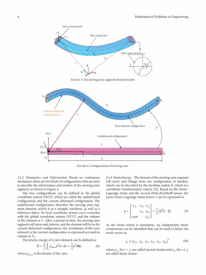
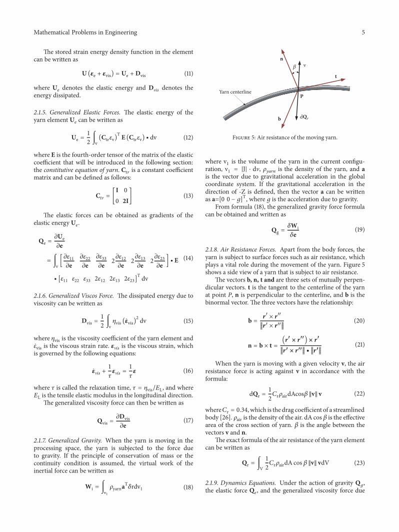
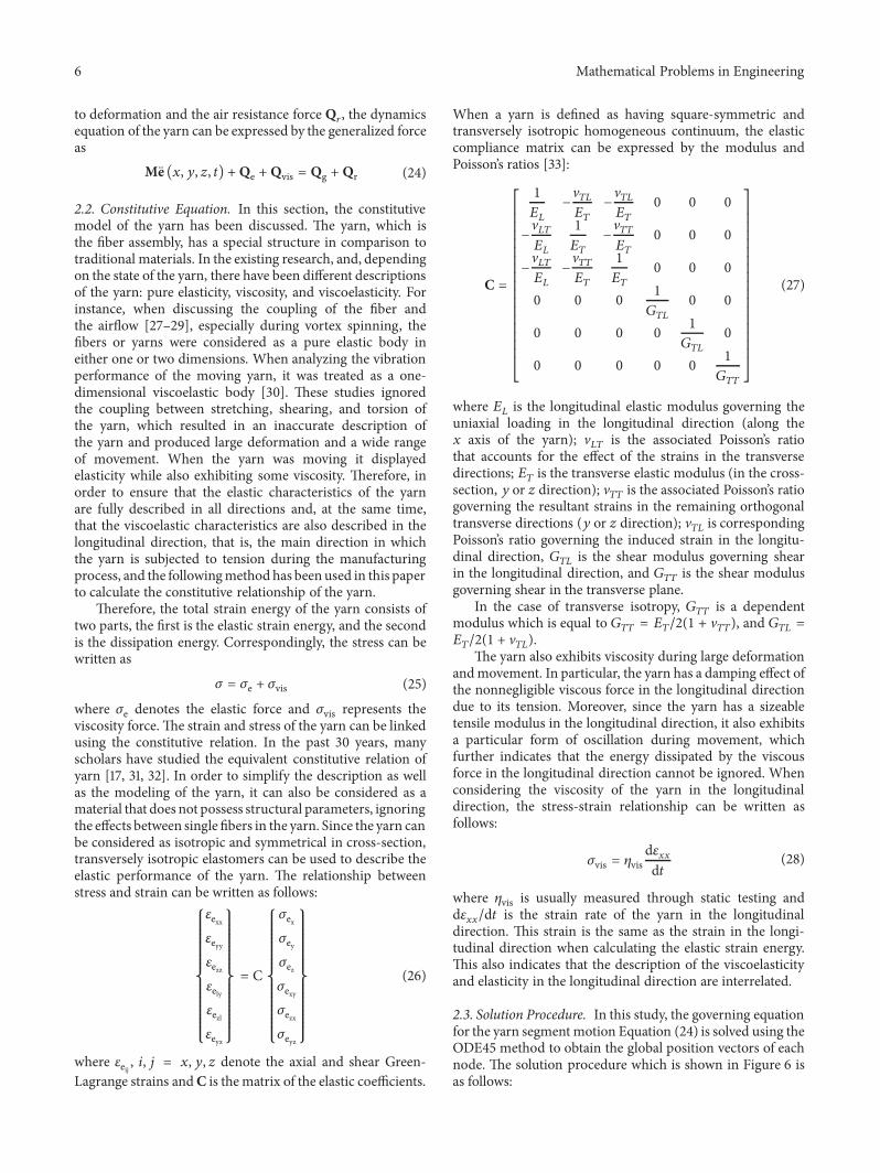
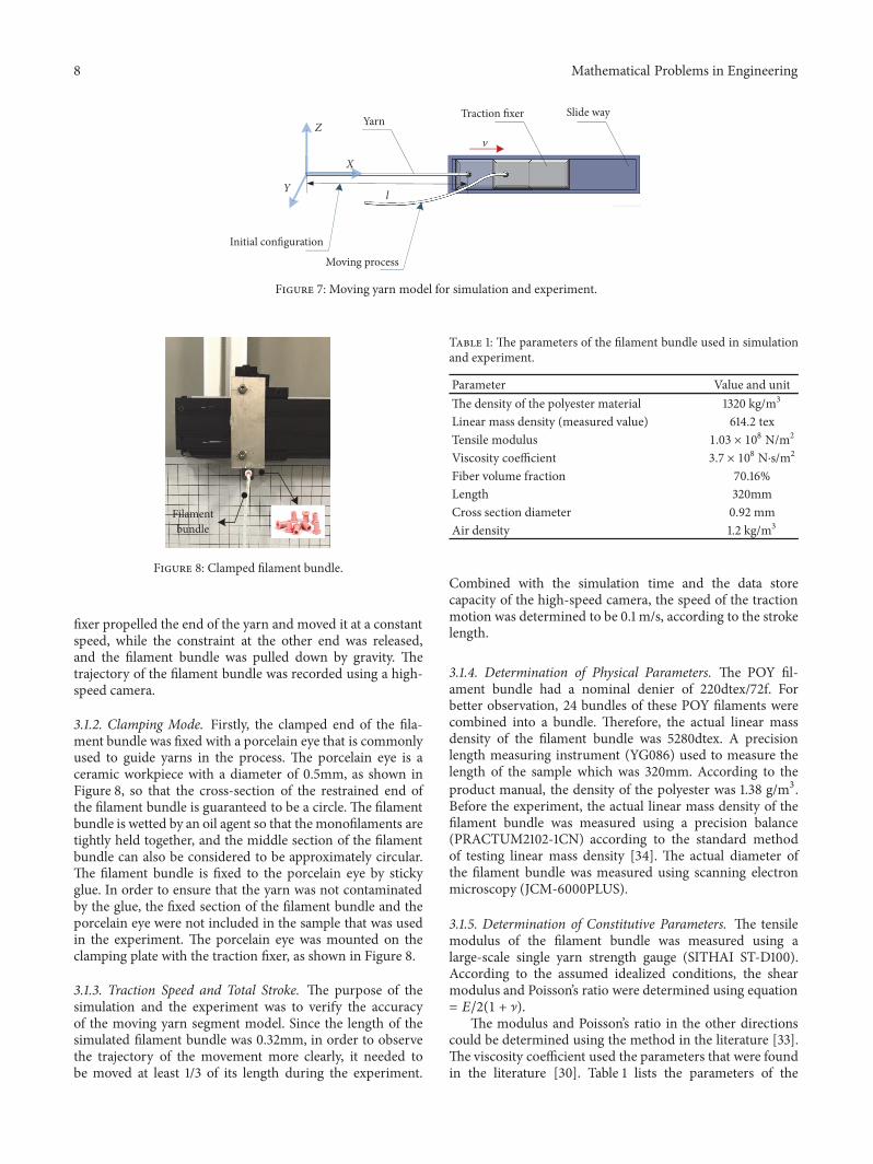
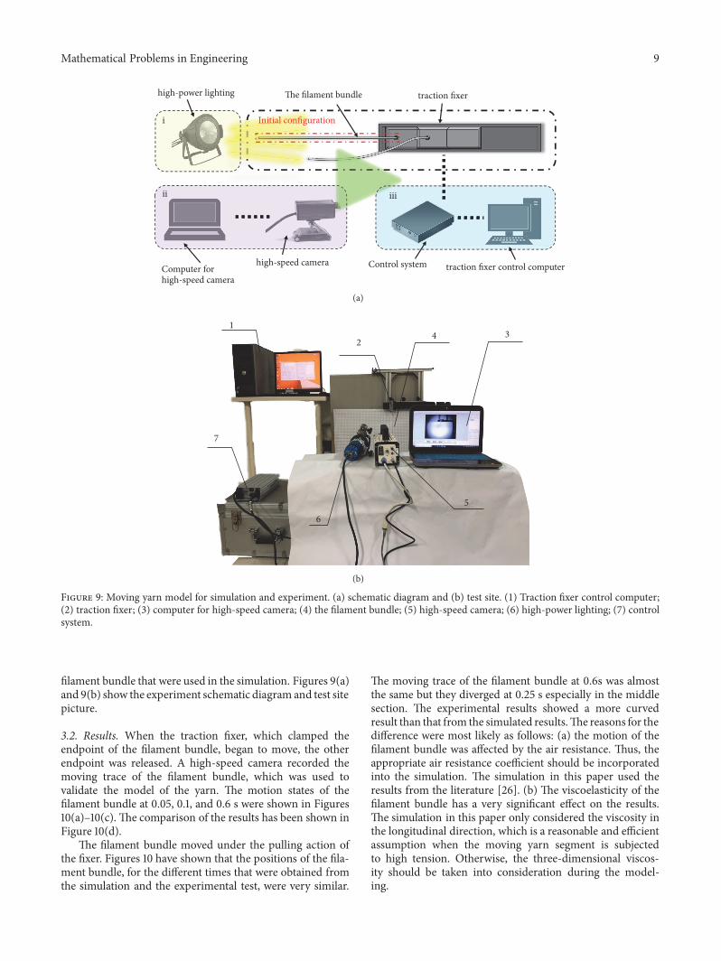
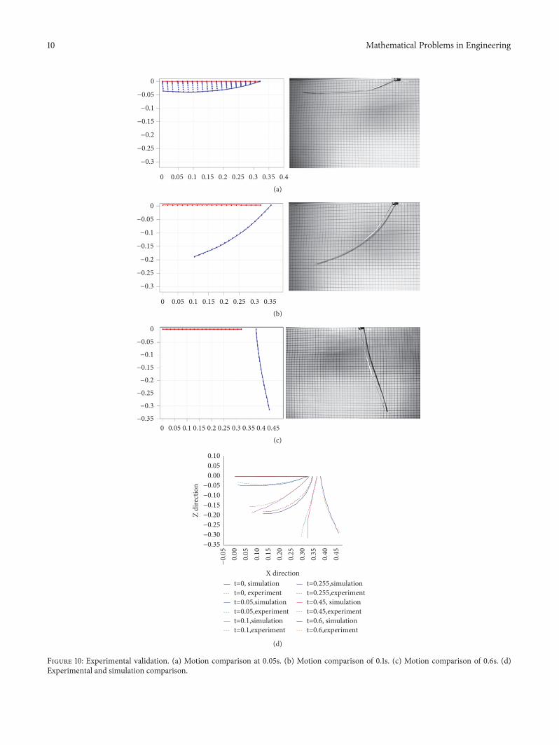
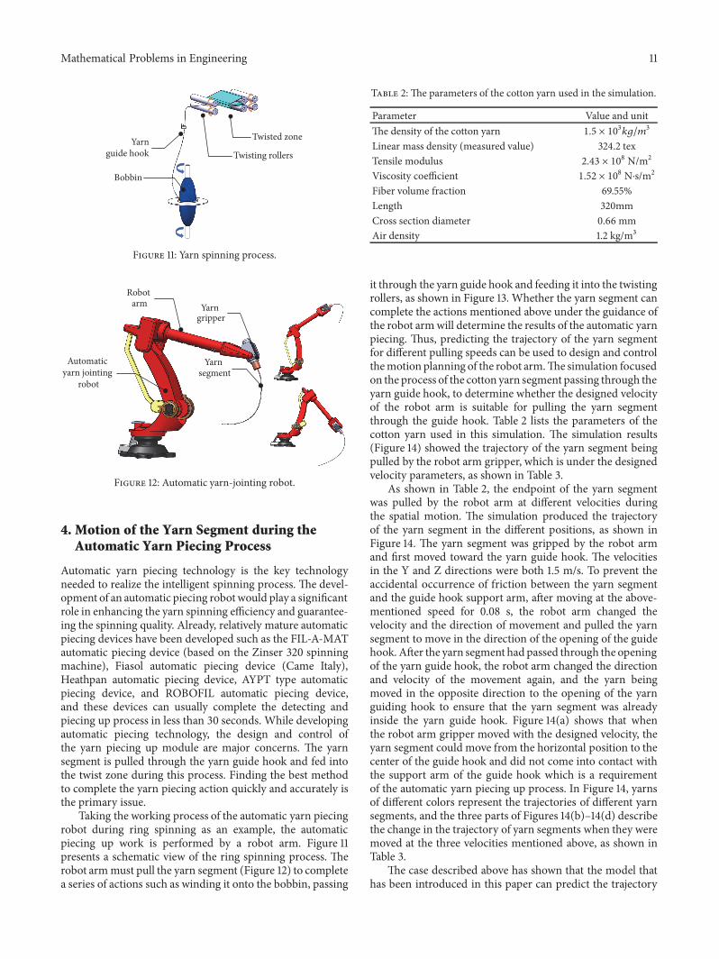
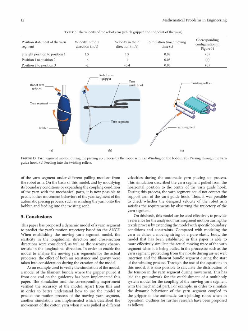

Hindawiwwwhindawicom Volume 2018
MathematicsJournal of
Hindawiwwwhindawicom Volume 2018
Mathematical Problems in Engineering
Applied MathematicsJournal of
Hindawiwwwhindawicom Volume 2018
Probability and StatisticsHindawiwwwhindawicom Volume 2018
Journal of
Hindawiwwwhindawicom Volume 2018
Mathematical PhysicsAdvances in
Complex AnalysisJournal of
Hindawiwwwhindawicom Volume 2018
OptimizationJournal of
Hindawiwwwhindawicom Volume 2018
Hindawiwwwhindawicom Volume 2018
Engineering Mathematics
International Journal of
Hindawiwwwhindawicom Volume 2018
Operations ResearchAdvances in
Journal of
Hindawiwwwhindawicom Volume 2018
Function SpacesAbstract and Applied AnalysisHindawiwwwhindawicom Volume 2018
International Journal of Mathematics and Mathematical Sciences
Hindawiwwwhindawicom Volume 2018
Hindawi Publishing Corporation httpwwwhindawicom Volume 2013Hindawiwwwhindawicom
The Scientific World Journal
Volume 2018
Hindawiwwwhindawicom Volume 2018Volume 2018
Numerical AnalysisNumerical AnalysisNumerical AnalysisNumerical AnalysisNumerical AnalysisNumerical AnalysisNumerical AnalysisNumerical AnalysisNumerical AnalysisNumerical AnalysisNumerical AnalysisNumerical AnalysisAdvances inAdvances in Discrete Dynamics in
Nature and SocietyHindawiwwwhindawicom Volume 2018
Hindawiwwwhindawicom
Dierential EquationsInternational Journal of
Volume 2018
Hindawiwwwhindawicom Volume 2018
Decision SciencesAdvances in
Hindawiwwwhindawicom Volume 2018
AnalysisInternational Journal of
Hindawiwwwhindawicom Volume 2018
Stochastic AnalysisInternational Journal of
Submit your manuscripts atwwwhindawicom