Embed Size (px)
Citation preview
Modeling and Simulation of Asteroid Retrieval Using aFlexible Capture Mechanism
Havard Fjær Grip, Masahiro Ono,J. Balaram, Jonathan Cameron, Abhinandan Jain, Calvin Kuo, Steven Myint, Marco Quadrelli
NASA Jet Propulsion LaboratoryCalifornia Institute of Technology
4800 Oak Grove Dr.Pasadena, CA 91109
Abstract—The National Aeronautics and Space Administrationis currently considering an Asteroid Redirect Mission (ARM),the goal of which is to bring a near-Earth asteroid into lunarorbit for inspection by a team of human astronauts. In thispaper we present the results of a simulation study that focuseson the challenge of capturing a target asteroid using a roboticspacecraft. This simulation study was conducted in parallelwith an ongoing mechanical design process, with the goal ofproviding feedback on specific design concepts, deriving high-level design targets via optimization, and exploring the tradespace of the capture problem independently. We present anddiscuss several simulation models, the results of which haveinfluenced the evolution of the ARM project to date.
TABLE OF CONTENTS
1 INTRODUCTION . . . . . . . . . . . . . . . . . . . . . . . . . . . . . . . . . . 12 BACKGROUND . . . . . . . . . . . . . . . . . . . . . . . . . . . . . . . . . . . 23 CAPTURE PHASES . . . . . . . . . . . . . . . . . . . . . . . . . . . . . . . 34 SPIDER-WEB CAPTURE MECHANISM . . . . . . . . . . . 55 INFLATABLE CAPTURE MECHANISM . . . . . . . . . . . 76 ABSTRACT 6-DOF JOINT . . . . . . . . . . . . . . . . . . . . . . . 107 DESIGN OPTIMIZATION . . . . . . . . . . . . . . . . . . . . . . . . . 108 PARAMETRIC SWEEPS . . . . . . . . . . . . . . . . . . . . . . . . . . . 139 CONCLUDING REMARKS . . . . . . . . . . . . . . . . . . . . . . . . 13
REFERENCES . . . . . . . . . . . . . . . . . . . . . . . . . . . . . . . . . . . . 14
1. INTRODUCTIONThe National Aeronautics and Space Administration (NASA)is currently considering the possibility of an Asteroid RedirectMission (ARM), the goal of which is to bring a small near-Earth asteroid (NEA) into lunar orbit for inspection by a teamof human astronauts. A robotic Asteroid Retrieval Vehicle(ARV) would be responsible for capturing the asteroid—measuring up to 13 m in diameter with a mass of up to1,000,000 kg—and bringing it into lunar orbit, while aseparately launched crew vehicle would carry the astronautsto and from the asteroid. The Asteroid Redirect Missionwould enhance our understanding of NEAs, demonstrate newtechnologies, and lay the groundwork for future missions, forpurposes such as resource mining and planetary defense.
The ARV must be capable of rendezvousing with, capturing,and de-spinning the target asteroid before transporting it intolunar orbit. This process is subject to significant uncertaintiesrelated to the composition, shape, and mass of the asteroid.
Copyright 2013 California Institute of Technology. Government sponsorshipacknowledged.
A further complicating factor is the spin state of the asteroid:it is likely to be tumbling rather than spinning about a well-defined axis, and may exhibit instantaneous spin rates of asmuch as 2 RPM. The design of a capture system that is robustagainst these uncertainties is a challenging task involving anumber of competing demands and tradeoffs in the areas ofmechanical design and guidance, navigation, and control.
While the capture system could be constructed in a number ofdifferent ways, a study by the Keck Institute for Space Studiesat Caltech [1] concluded that the most promising design is aflexible bagging mechanism attached to the spacecraft, whichwould fully envelop and cinch down on the asteroid. Sucha mechanism would be suitable both for a solid rock and arubble pile, and would thus ensure robustness against uncer-tainty in the asteroid composition. The complex motion ofthe asteroid places high demands on the capture mechanism,which is responsible for maintaining adequate separation be-tween the asteroid and the spacecraft throughout the captureevent, while also cushioning the spacecraft against excessiveloads. Of particular concern in this context are the solar arraydrive assemblies (SADAs), which are expected to tolerate amaximum bending moment equivalent to an acceleration ofapproximately 0.1 g at the middle of each deployed solarpanel.
Topics of This Paper
In this paper we describe the results of a simulation study intothe dynamics of an asteroid capture event. This study hasbeen conducted in parallel with an ongoing mechanical de-sign process at NASA’s Jet Propulsion Laboratory (JPL), withthe goal of providing feedback on specific design concepts,deriving target design parameters via optimization, and ex-ploring the trade space of the capture problem independently.
The simulation team worked closely with the mechanicaldesign team that was responsible for developing the capturemechanism. Since the device was new and quite unlike thatin any conventional spacecraft or robotic device, both teamswere forced into exploratory spirals of concept developmentand feasibility assessment, with the results from each teaminforming the activities of the other. The teams also had to de-velop and refine the methodologies associated with the designprocess itself, such as defining the appropriate performancemetrics to design to and monitor in the simulation (e.g.,monitoring key structural loads and geometric clearances),determining the level of simulation fidelity that was mostappropriate for a design at a particular level of maturity(e.g., the modeling of the compliance provided by the capturedevice as a generalized spring-damper system), establishingthe kinds of information that needed to be exchanged betweenthe teams (e.g., mathematical abstractions of specific bag-
1
to-line friction interactions or pneumatic structure stiffness),and specifying the cross-validation that was necessary at eachstep of the process (e.g., comparing the simulation loads fora capture scenario that was particularly simple and thereforeamenable to being modeled in a tool such as Adams).
Background and Capture Phases— We begin in Section 2by presenting some basic background information on therotational dynamics of rigid objects in general and NEAs inparticular. In Section 3 we summarize the different phases ofthe capture problem and address the topic of how to approacha tumbling asteroid in preparation for capture. Although itis theoretically possible for a spacecraft equipped with suf-ficiently large thrusters to match the tumbling motion of theasteroid, such a solution is not considered feasible because ofthe associated fuel requirements. Thus, it is instead assumedthat the spacecraft will approach the asteroid along a well-defined inertial vector while spinning about its symmetryaxis, and that the capture event itself is passive from a GN&Cstandpoint. The choice of approach vector, spin rate, andcapture epoch all have major influences on the transientdynamics of the capture event and the eventual steady-statemotion regime of the combined spacecraft-asteroid system.
Simulation models—Due to the many unique and unexploredaspects of the asteroid capture problem, some of the tradesinvolved in designing a viable capture system have onlybecome apparent in the course of the simulation study. Ourpresentation in this paper mirrors the evolving nature ofthe work that has been conducted, in that we study severaldifferent models with different objectives in mind.
In Section 4 we focus on a model representing a design inwhich robotic limbs extend from the spacecraft bus to form alarge barrel. A drawstring bag inside this barrel is attached tothe limbs via flexible winch-controlled cinch lines. A centralidea of this design is that, after the initial short-durationcinching event, enough flexibility should be left in the systemto facilitate passive damping of the tumbling motion towardmajor-axis spin. This design concept, which we refer to asthe spider-web capture mechanism, was abandoned due tomechanical design and packaging considerations; however,we discuss it here for the sake of completeness.
In Section 5 we focus on a model created as a rough represen-tation of an alternative design, where the robotic limbs havebeen replaced by an inflatable exoskeleton attached directly tothe spacecraft bus. In this design, the bag collapses around theasteroid with the help of actively controlled winches, whileadditional inflatable members help keep the spacecraft andthe asteroid separated.
In Section 6 we focus on a model that does not represent aparticular design, but rather an abstract representation of acapture mechanism with an isolation device represented by a6-DOF joint. This model allows us to explore, in a generalway, the requirements that must be imposed on such anisolation device in order to ensure robustness against variousuncertainties.
Each of the three simulation models is based on the same ba-sic building blocks of rigid bodies connected via translationaland rotational spring-dampers. The result is clearly a simplifi-cation of a complex physical system; we stress, however, thatthe goal here is not to investigate specific designs at a detaillevel, but to gain a high-level understanding of the interplaybetween various factors such as capture geometry, flexibilityand damping of the capture mechanism, the tumbling motion
of the asteroid, and the relative state of the spacecraft at thetime of capture.
Implementation—The simulations were based on the Darts/D-shell architecture for spacecraft dynamics simulation, devel-oped at JPL (see, e.g., [2]). In addition to point simulations forparticular configurations, large-scale parametric sweeps wereconducted to cover a wide range of asteroid masses, shapes,and rotational states. Moreover, the simulation models wereused as components of an optimization algorithm in orderto synthesize a set of desirable parameters for a capturemechanism. These topics are discussed in Sections 7 and 8.
2. BACKGROUNDFor a rigid body subject to no external torques, the angularvelocity ω ∈ R3 around the center of mass (decomposed inbody-fixed coordinates) is governed by the Euler equations
Jω =−ω× Jω, (1)
where J is the inertia around the center of mass. By aligningthe body-fixed frame with the principal axes of the body,the inertia matrix can be written as J = diag(I1, I2, I3), whereI1, I2, and I3 are the principal-axis inertias. From (1) it iseasy to see that ω is constant if and only if ω and Jω areparallel. This is always the case when the principal-axisinertias are identical, but in general ω remains constant onlyif it is aligned with one of the principal axes. When this isnot the case, both the direction and magnitude of ω may varyover time, and the body is said to tumble.
A body with three distinct inertias is called a tri-inertialbody, whereas a body with two identical inertias is calledan inertially axi-symmetrical body. For tri-inertial bodies,the analytical solution of (1) follows elliptical curves that lieon the surface of two ellipsoids defined by the requirementsthat the kinetic energy and the angular momentum of thesystem are both preserved. For axi-symmetrical bodies, themotion can be more conveniently described by representingthe attitude using Euler angles labeled precession, nutation,and spin, of which the nutation angle remains constant andthe precession and spin angles change at constant rates.
If the rotating body is augmented with damped flexiblemodes, then these will tend to be excited by the tumblingmotion, resulting in a loss of rotational energy. This energyloss eventually leads to convergence toward constant spinaround the principal axis with the largest inertia (i.e., major-axis spin). For further details, see [3].
Near-Earth Asteroids
Due to the energy loss associated with flexible modes, celes-tial objects tend to stabilize toward major-axis spin over time.The relaxation (or characteristic) time, defined as the timerequired for a tumbling object to achieve a principal axis spin,for an asteroid of radius r and spin period T , is proportionalto T 3 and inversely proportional to r2 [4]. Thus, slow rotatingspinners take a long time to achieve principal axis spin, as dosmall asteroids. For small objects such as near-Earth asteroidsin the 10-m class, the convergence is thought to occur on asignificantly longer time scale than the average time since lastcollision. Consequently, it is expected that the ARM targetasteroid may tumble.
The instantaneous spin rates for large objects is bounded bythe rubble pile limit spin barrier at which centrifugal forces
2
disaggregate bodies composed of a loose collection of smallerobjects (i.e., rubble) held together by gravity. Smaller objects,being more solid, are not constrained by this limit, and at theextreme end are seen to approach or slightly exceed spin ratesof as much as 2 RPM. We therefore take 2 RPM, un-relaxedobjects as the design point for our analysis and simulations.For a number of bounding analysis cases, we consider simplynutated axi-symmetrical bodies; however, we also considerfully tumbling tri-inertial objects.
Coordinate Frames
In each of the simulations presented in this paper, the initialangular momentum vector of the asteroid is aligned withthe z axis of the inertial reference coordinate frame. Whendiscussing inertially axi-symmetrical asteroids, we align thesymmetry axis with the asteroid’s z axis; for tri-inertialasteroids (modeled as ellipsoids), we align the smallest semi-axis with the z axis. We define the axes of the spacecraftaccording the convention illustrated in Figure 1.Darts Lab Mobility & Robotic Systems - 347
Simulation Settings (Case 2)
1
x z y
Figure 1. Spacecraft axes convention
3. CAPTURE PHASESThe asteroid capture problem is composed of the followingphases:
• Approach phase, in which the spacecraft gets in closeproximity of the asteroid, and spins up to match the asteroidrate. The objective of this phase is to characterize the asteroidproperties and to set up for the close proximity operations.• Grapple phase, in which the capture bag is cinched down,and the motion of the spacecraft catches up with the motion ofthe asteroid. The asteroid’s tumbling motion may be dampedby passive energy bleeding.• Despin phase, in which the bag is further tightened aroundthe asteroid, and the asteroid is detumbled and despun usingactive thrusting. In this phase the system mass properties aremanaged and the despun state is achieved.• Departure phase, in which the entire asteroid/spacecraftsystem is placed into a trajectory for transportation to lunarorbit.
GN&C Sequence
The GN&C sequence to achieve these goals includes:
• Far-field rendezvous and loose station-keeping phase. Thisphase is Ground-directed to get safely within a few kilome-ters, maintain station to within approximately 100 m, andinitiate relative position estimation.• Spin state and shape characterization phase. In this phase,closed-loop proximity motions (e.g., circumnavigation) arerequired. Asteroid characterization is not required to be real-time and can be conducted on the ground.• Pre-capture positioning phase. This phase includes thefinal approach along an inertially-fixed direction, and trans-
lation to the final stand-off point (approximately 50 m) on theapproach vector.• Synchronize spin phase, in which the spacecraft is spun upto an appropriate rate to best match the motion of the asteroid.• Final translation phase, closing at constant rate (approxi-mately 0.1 m/s) along the approach vector.• Capture phase, which detects entry of the asteroid into thecapture mechanism, controlled stop of translational motion,disable control, and initiate capture.• Despin phase, where closed-loop GN&C is engaged toremove any remaining tumbling motion and to despin thecombined system.
Table 1 lists some of the functionality that may need to beconsidered in the design of the GN&C system.
Approach Strategy
Our focus in this paper is on the grapple phase; in particular,we are interested in the dynamics of the combined asteroid-spacecraft system from the time that contact is first made untilthe start of the despin phase. The capture dynamics is funda-mentally affected by the state of the spacecraft relative to theasteroid at the start of the grapple phase, and it is thereforeintrinsically linked to the choice of approach strategy.
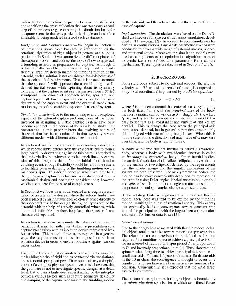
Figure 2. Illustration of the angular momentum approach fora prolate asteroid with an 80◦ nutation angle. The spacecraftis lined up with the angular momentum vector while matchingthe precession rate of the asteroid. The time-varying angularvelocity traces a cone around the angular momentum vector,but appears constant in the spacecraft frame. The outline ofthe capture bag (before closing) is shown as a transparentcylinder.
Angular-Momentum Approach—For a simple principal-axisspinner, choosing an approach strategy is straightforward:since the body spins at a constant rate around its angularmomentum vector, we may approach along this vector whilematching the spin rate, thereby canceling all relative motionbetween the spacecraft and asteroid.
3
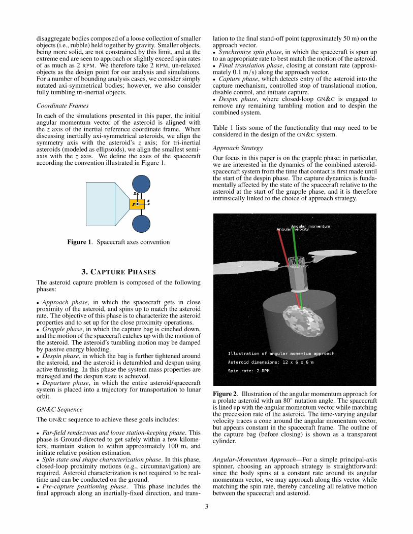
Asteroid capture GN&C functions
Phase Sensing Estimation Guidance Actuators Control ModelsApproach:spacecrafttranslate
Cameras; laserranging; closeupillumination;IMU; star tracker
Stereo depthmaps; spin-state estimation;attitude filter
Stagedapproach;best viewingdirection;preferred axis
RCS, RWA 3-axis stationkeep; trackapproachwaypoints;SEP deltaV
Shape; angularmomentum;rigid body massproperties
Approach:spacecraft spin-up
IMU; camera;star tracker;LIDAR
Relative stateprediction; visualconfirmation
Achieve bestmatch to spin
RCS; RWA 3-axis control Spacecraft massproperties; fuelslosh
Grapple: bagcinch-down
IMU; grappleforce/torquesensing
Cinchconfirmation
Cinch tensionsetpoints
Winch linetensioner
Pre-stress tosetpoint
Off-line Monte-Carlo analysisof bag/asteroidinteractionon multibodysystem
Grapple:asteroid nutationdamping
IMU Rotational stateobserver
Track predictedsystem rotationprofile
Winch linetensioner
Tensionmodulation;winch
Line/bag friction;line viscoelasticdamping; fuelslosh
Despin: bagcinch tighten
IMU Cinch tightenconfirm; CMand inertialpropertiesestimation
Cinch tensionsetpoint; CMadjust; cinch lineadjust
Winch linetensioner
Servo tensionto setpoint;reposition cinchplane centerfor system CMadjust
Compositemass properties;fuel slosh;possible thrusterarticulation
Despin: systemdetumble/despin
IMU;force/torquesensing atgrapple; startracker
Spin state;spacecraftstructureexcitation state
Despin profile RCS; RWA Minimum-disturbance andminimum-fuelcontrol
Structureflexibility; fuelslosh; thrustallocation
Departure IMU; star tracker Spacecraftstate; CM andinertia state
Final CM adjust;departuretrajectory
Winch linetensioner; SEP;RCS; RWA
Fine positionCM; SEP deltaVcontrol
Thrust allocation
Table 1.
One may generalize this approach strategy for a tumblingasteroid by again approaching along the angular momentumvector. In this case, one cannot match the motion of theasteroid precisely, since the angular velocity is not alignedwith the angular momentum vector. Instead, one may choosea spin rate that in some sense minimizes the average relativemotion. In this project, the angular-momentum approachwas considered in the context of inertially axi-symmetricalasteroids, with the spacecraft spin rate chosen according toone of the following strategies:
• Matching of asteroid precession rate. By matching theprecession rate, the motion of the asteroid relative to thespacecraft is canceled except for the relative spin rate. Thus,the asteroid as seen from the spacecraft appears to standstill, except for a constant spin rate around the symmetryaxis of the asteroid. Matching the precession rate may bea good choice for approaching a prolate asteroid, since, if itis rotating close to major-axis spin, the relative spin rate willbe much smaller than the total spin rate (i.e., the norm of theangular velocity). An illustration of this situation, producedby the Darts/Dshell visualization engine, is shown in Figure2.• Matching of asteroid precession + relative spin rate. Thischoice leads to a more complex relative motion between thespacecraft and asteroid, but it may be a good choice forapproaching an oblate asteroid. If the asteroid is rotatingclose to major-axis spin, the symmetry axis of the asteroid,as seen from the spacecraft, will trace a cone, while thetransverse axes will oscillate with relatively small amplitudes,leading to a “nodding” appearence.
Angular-Velocity Match Approach—Another way to general-ize the approach strategy for simple spinners is by matchingthe angular velocity precisely at a particular epoch. Based onthe close observation of the spin state and shape characteri-zation of the target asteroid from the ARV, the future motionof the asteroid is precisely predicted to select an exact futureepoch at which to grab it. The approach vector is chosen asthe predicted angular velocity vector at this epoch, and thespacecraft spin rate is chosen to match the predicted instanta-neous spin rate of the asteroid. The result is that the relativemotion between the asteroid and the spacecraft is canceledat the time of capture. A fast-closing capture mechanismis a prerequisite for this strategy, since the relative motionis only canceled for an instant. The freedom in the choiceof capture epoch (and thus approach vector and spin rate)can be used, for example, to make the grapple phase moregentle on the spacecraft or to reduce the fuel requirements forthe subsequent de-spin. When applying the angular-velocitymatch approach in this paper, the capture epoch is chosen tominimize the derivative of the angular velocity at the timeof capture. Figure 3 illustrates the angular-velocity matchapproach.
Sideways Grab Approach—Another approach strategy con-sidered in this paper involves approaching along a vectornormal to the angular momentum vector, without matchingany of the rotation of the asteroid. While this strategy mayseem counterintuitive, we study it for two primary reasons:
• The sideways grab can be viewed as a worst case ofmismatch between the spacecraft and asteroid motion. It is
4
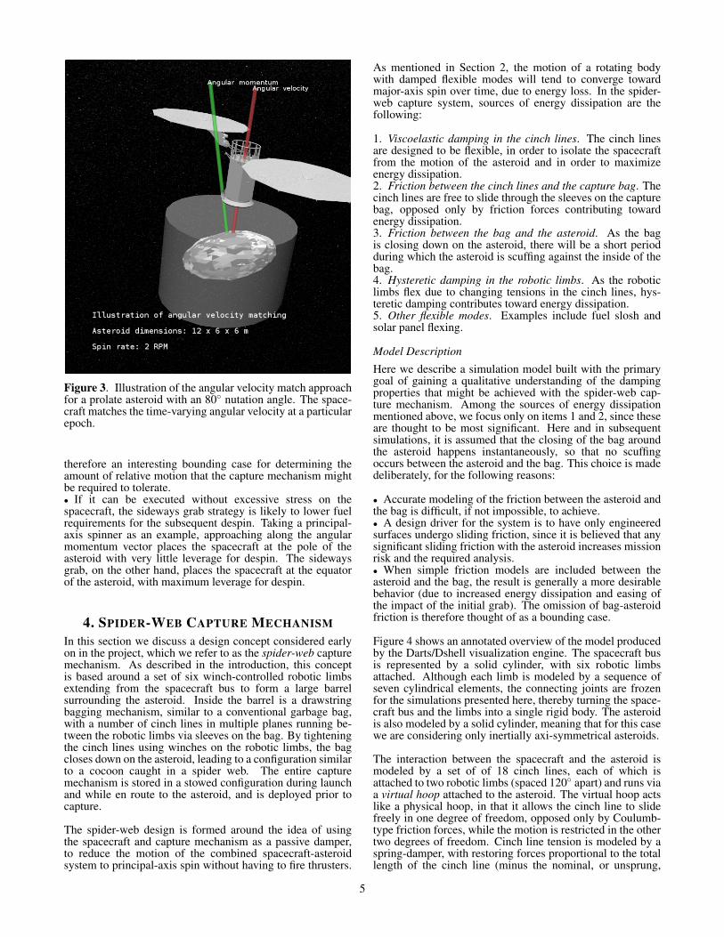
Figure 3. Illustration of the angular velocity match approachfor a prolate asteroid with an 80◦ nutation angle. The space-craft matches the time-varying angular velocity at a particularepoch.
therefore an interesting bounding case for determining theamount of relative motion that the capture mechanism mightbe required to tolerate.• If it can be executed without excessive stress on thespacecraft, the sideways grab strategy is likely to lower fuelrequirements for the subsequent despin. Taking a principal-axis spinner as an example, approaching along the angularmomentum vector places the spacecraft at the pole of theasteroid with very little leverage for despin. The sidewaysgrab, on the other hand, places the spacecraft at the equatorof the asteroid, with maximum leverage for despin.
4. SPIDER-WEB CAPTURE MECHANISMIn this section we discuss a design concept considered earlyon in the project, which we refer to as the spider-web capturemechanism. As described in the introduction, this conceptis based around a set of six winch-controlled robotic limbsextending from the spacecraft bus to form a large barrelsurrounding the asteroid. Inside the barrel is a drawstringbagging mechanism, similar to a conventional garbage bag,with a number of cinch lines in multiple planes running be-tween the robotic limbs via sleeves on the bag. By tighteningthe cinch lines using winches on the robotic limbs, the bagcloses down on the asteroid, leading to a configuration similarto a cocoon caught in a spider web. The entire capturemechanism is stored in a stowed configuration during launchand while en route to the asteroid, and is deployed prior tocapture.
The spider-web design is formed around the idea of usingthe spacecraft and capture mechanism as a passive damper,to reduce the motion of the combined spacecraft-asteroidsystem to principal-axis spin without having to fire thrusters.
As mentioned in Section 2, the motion of a rotating bodywith damped flexible modes will tend to converge towardmajor-axis spin over time, due to energy loss. In the spider-web capture system, sources of energy dissipation are thefollowing:
1. Viscoelastic damping in the cinch lines. The cinch linesare designed to be flexible, in order to isolate the spacecraftfrom the motion of the asteroid and in order to maximizeenergy dissipation.2. Friction between the cinch lines and the capture bag. Thecinch lines are free to slide through the sleeves on the capturebag, opposed only by friction forces contributing towardenergy dissipation.3. Friction between the bag and the asteroid. As the bagis closing down on the asteroid, there will be a short periodduring which the asteroid is scuffing against the inside of thebag.4. Hysteretic damping in the robotic limbs. As the roboticlimbs flex due to changing tensions in the cinch lines, hys-teretic damping contributes toward energy dissipation.5. Other flexible modes. Examples include fuel slosh andsolar panel flexing.
Model Description
Here we describe a simulation model built with the primarygoal of gaining a qualitative understanding of the dampingproperties that might be achieved with the spider-web cap-ture mechanism. Among the sources of energy dissipationmentioned above, we focus only on items 1 and 2, since theseare thought to be most significant. Here and in subsequentsimulations, it is assumed that the closing of the bag aroundthe asteroid happens instantaneously, so that no scuffingoccurs between the asteroid and the bag. This choice is madedeliberately, for the following reasons:
• Accurate modeling of the friction between the asteroid andthe bag is difficult, if not impossible, to achieve.• A design driver for the system is to have only engineeredsurfaces undergo sliding friction, since it is believed that anysignificant sliding friction with the asteroid increases missionrisk and the required analysis.• When simple friction models are included between theasteroid and the bag, the result is generally a more desirablebehavior (due to increased energy dissipation and easing ofthe impact of the initial grab). The omission of bag-asteroidfriction is therefore thought of as a bounding case.
Figure 4 shows an annotated overview of the model producedby the Darts/Dshell visualization engine. The spacecraft busis represented by a solid cylinder, with six robotic limbsattached. Although each limb is modeled by a sequence ofseven cylindrical elements, the connecting joints are frozenfor the simulations presented here, thereby turning the space-craft bus and the limbs into a single rigid body. The asteroidis also modeled by a solid cylinder, meaning that for this casewe are considering only inertially axi-symmetrical asteroids.
The interaction between the spacecraft and the asteroid ismodeled by a set of of 18 cinch lines, each of which isattached to two robotic limbs (spaced 120◦ apart) and runs viaa virtual hoop attached to the asteroid. The virtual hoop actslike a physical hoop, in that it allows the cinch line to slidefreely in one degree of freedom, opposed only by Coulumb-type friction forces, while the motion is restricted in the othertwo degrees of freedom. Cinch line tension is modeled by aspring-damper, with restoring forces proportional to the totallength of the cinch line (minus the nominal, or unsprung,
5

length), and viscoelastic damping forces proportional to thederivative of this length. Figure 5, which shows the asteroidand capture mechanism as seen from the spacecraft point ofview, gives a better picture of how a single cinch line attachesto the limbs and to the asteroid.
Figure 4. An overview of the Darts/Dshell simulationmodel for the spider-web capture mechanism, illustrating thespacecraft, asteroid, robotic limbs, and the cinch line-hoopinteraction model
Figure 5. The asteroid and capture system as seen from thespacecraft point of view
The approach strategy considered at this stage is the angular-momentum approach.
Results
The adjustable parameters for the capture mechanism arethe stiffness and damping constants, as well as the nominal
Simulation parameters, spider-web example
Value UnitAsteroidMass 500,000 kg
Radius 3.5 m
Height 3 m
Spin rate 1 deg/s
Nutation angle 30 deg
SpacecraftMass 15,000 kg
Bus height 6 m
Bus radius 1.5 m
Distance of CM to asteroid CM 13.5 m
Capture mechanismCinch line stiffness constant 2 N/m
Cinch line damping constant 15 N/(m/s)
Cinch line pre-stress 2 N
Cinch line-hoop friction coefficient 0.1 1
Table 2.
length (or, equivalently, the pre-stress), of the cinch lines,together with the friction coefficient (the ratio of frictionforce to normal force) for the cinch line-hoop interaction. Anumber of point simulations were conducted with selectedparameterizations for the capture mechanism, combined withdifferent asteroid inertial properties and initial states. Themain conclusions from these simulations are the following:
• For the limited number of cases studied, the simulationsconfirmed that the tumbling motion of the asteroid wasasymptotically damped out, so that the overall system con-verged toward major-axis spin.• In order to achieve damping on a time scale of a fewdays, the cinch lines were chosen to be very flexible, thusallowing for a large amount of relative motion. It is not clearwhether the resulting system would be physically realizablewith space-qualified materials.• In the simulation model used, the energy dissipation isdominated by viscoelastic damping; changes in the frictioncoefficient have a more limited effect on the outcome.• The combined spacecraft-asteroid system tends to convergetoward a flat spin, where the axis of rotation is close tonormal to the symmetry axis of the spacecraft bus. This isconsidered desirable, since it increases the thruster lever armfor subsequent de-spin.2
As an example to illustrate these points, we present simu-lation results for a specific case defined by the parameterslisted in Table 2. In this example, the angular momentumvector points directly along the inertial z axis. Figure 6 showsthe angular velocity of the asteroid, in inertial coordinates,over a 48-h period after the capture. It can be seen thatthe angular velocity starts with both a z component anda smaller component in the x-y plane. Over time, the xand y components are damped due to energy loss, and theangular velocity will eventually converge toward simple spinaround the inertial z axis. Figure 7 similarly shows theangular velocity of the spacecraft. Because the spacecraft has
2Note that this is a function of the mass geometry of the combined spacecraft-asteroid system—by adding the mass of the spacecraft to the asteroid, themajor axis of the combined system may be shifted.
6
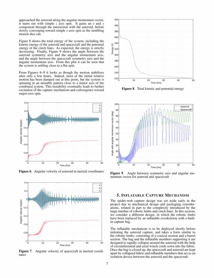
approached the asteroid along the angular momentum vector,it starts out with simple z axis spin. It gains an x and ycomponent through the interaction with the asteroid, beforeslowly converging toward simple z-axis spin as the tumblingmotion dies out.
Figure 8 shows the total energy of the system, including thekinetic energy of the asteroid and spacecraft and the potentialenergy of the cinch lines. As expected, the energy is strictlydecreasing. Finally, Figure 9 shows the angle between theasteroid symmetry axis and the angular momentum axis,and the angle between the spacecraft symmetry axis and theangular momentum axis. From this plot it can be seen thatthe system is settling close to a flat spin.
From Figures 6–9 it looks as though the motion stabilizesafter only a few hours. Indeed, most of the initial relativemotion has been damped out at this point, but the system isspinning in an unstable pattern close to a minor axis of thecombined system. This instability eventually leads to furtherexcitation of the capture mechanism and convergence towardmajor-axis spin.
0 10 20 30 40 50−1
−0.8
−0.6
−0.4
−0.2
0
0.2
0.4
Time (hrs)
Ang
ular
vel
ocity
(de
g/s)
xyz
Figure 6. Angular velocity of asteroid in inertial coordinates
0 10 20 30 40 50−1
−0.8
−0.6
−0.4
−0.2
0
0.2
0.4
Time (hrs)
Ang
ular
vel
ocity
(de
g/s)
xyz
Figure 7. Angular velocity of spacecraft in inertial coordi-nates
0 10 20 30 40 50220
240
260
280
300
320
340
360
380
400
420
Time (hrs)
Ene
rgy
(J)
Figure 8. Total kinetic and potential energy
0 10 20 30 40 500
10
20
30
40
50
60
70
80
90
100
Time (hrs)
Ang
le w
ith a
ngul
ar m
omen
tum
vec
tor
(deg
)
AsteroidSpacecraft
Figure 9. Angle between symmetry axis and angular mo-mentum vector for asteroid and spacecraft
5. INFLATABLE CAPTURE MECHANISMThe spider-web capture design was set aside early in theproject due to mechanical design and packaging consider-ations, related in part to the complexity introduced by thelarge number of robotic limbs and cinch lines. In this section,we consider a different design, in which the robotic limbshave been replaced by an inflatable exoskeleton with a built-in capture bag.
The inflatable mechanism is to be deployed shortly beforeinitiating the asteroid capture, and takes a form similar tothe robotic limbs, consisting of a conical section and a barrelsection. The bag and the inflatable members supporting it aredesigned to rapidly collapse around the asteroid with the helpof circumferential and axial winch cords sown into the fabric.Once the bag is closed up, the spacecraft and asteroid are keptapart by collapsed fabric and inflatable members that act as anisolation device between the asteroid and the spacecraft.
7

Model Description
The inflatable capture mechanism is modeled by attachingtwo sets of linear spring-dampers directly between the space-craft bus and the asteroid, as illustrated in Figure 10. Thereare six attachment points around the lower perimeter of thespacecraft bus, and six corresponding attachment points onthe asteroid, located on a circle around the asteroid centerof mass (CM) in a plane normal to the vector between theasteroid and spacecraft CMs. Twelve spring-dampers arecriss-crossed between the attachment points on the spacecraftand the attachment points on the asteroid. Another six spring-dampers are attached directly between the attachment pointson the spacecraft and the corresponding attachment points onthe asteroid. The two sets of spring-dampers are illustratedby the red and blue lines in Figure 11.
Figure 10. An overview of the Darts/Dshell simulationmodel for the inflatable capture mechanism, illustrating thespacecraft, asteroid, solar panels, and the spring-dampers.The inset shows the asteroid and capture mechanism as seenfrom the spacecraft point of view.
Darts Lab Mobility & Robotic Systems - 347
Asteroid
Inflatable bag
SADA
Simulation Settings (Case 2)
1
Straight spring-dampers
Crisscrossed
spring-dampers
Figure 11. Inflatable capture mechanism model
Simulation parameters, inflatable example
Value(s) UnitAsteroid
Mass 1,000,000 kg
Semi-axes 6, 6, and 3 m
Spin rate 2 RPM
Nutation angle 0 deg
SpacecraftMass 15,000 kg
Bus height 6 m
Bus radius 1.5 m
Distance of CM to asteroid CM 10 m
Capture mechanismStiffness, criss-crossed lines 4,000 N/m
Damping, criss-crossed lines 700 N/(m/s)
Stiffness, straight lines 5,000 N/m
Damping, straight lines 900 N/(m/s)
Asteroid attachment radius 3.5 m
Table 3.
The spring-damper configuration was originally motivatedby a particular design, in which the criss-crossed lines rep-resented a combination of axial winch cords and collapsedbag fabric, and the straight lines represented inflatable struts.However, as the design evolved, the spring-dampers came torepresent an inflatable isolation device between the spacecraftand the asteroid in a more abstract sense.
Also shown in Figure 10 are solar panels that have beenadded to the model. The solar panels are modeled as thincylinders mounted on zero-mass booms, which are attachedto the spacecraft bus via 3-DOF ball joints. The ball joints areendowed with 3-DOF torsional spring-dampers with stiffnessand damping constants set according to parameters receivedby the manufacturer.
The asteroid is modeled as a solid ellipsoid with three sep-arately adjustable semi-axes, allowing us to represent anytri-inertial rigid object. As before, it is assumed that thecapture itself takes place instantaneously, by attaching thespring-dampers between the spacecraft and the asteroid at aparticular epoch.
A set of example parameters, which we shall refer to through-out the rest of this section, is given in Table 3.
Relationship to Physical System
Given that the simulation model is an abstraction of the truephysical system, it is pertinent to ask how a quantitativerelationship between the two can be established. One wayof doing so is by deriving system-level stiffness and dampingparameters of the model in different degrees of freedom, andcomparing these to corresponding values for the physicalsystem, derived from more complex soft-goods modeling orexperiments. The results of this comparison can be usedto adjust the simulation model to match the properties ofa particular design, and, conversely, to synthesize designrequirements that must be met by the mechanical system.
To obtain system-level stiffness and damping constants forthe capture mechanism, we consider the changes in restoring
8
forces and damping forces due to small deflections of thespacecraft’s position and attitude relative to the asteroid,around a setpoint defined by the nominal spring-damperlengths and zero velocities. Letting fr and τr denote the3-dimensional vectors of restoring forces and torques withrespect to some reference point, and letting ∆p and ∆Θ denotethe three-dimensional vectors of relative position and attitudedeflections with respect to the same reference point, it can beshown that the Jacobian of [ fr;τr] with respect to [∆p;∆Θ] isgiven by
−[
∑Ni=1 kieieTi ∑
Ni=1 kieieTi S(ri)
T
∑Ni=1 kiS(ri)eieTi ∑
Ni=1 kiS(ri)eieTi S(ri)
T
],
where N is the number of spring-dampers, ki is the stiffnessconstant of spring-damper i, ei is the unit vector pointing fromthe attachment point of spring-damper i on the spacecraftto the attachment point on the asteroid, and ri is the vectorfrom the reference point to the attachment point of spring-damper i on the spacecraft. The function S(·), which mapsfrom R3 to the set of 3×3 skew-symmetric matrices, is suchthat S(x)y = x× y for all x,y ∈ R3. We refer to the negativeof the Jacobian as the stiffness matrix K. Similarly, lettingfd and τd denote damping forces and torques, the Jacobianof [ fd ;τd ] with respect to the vector [∆v;∆ω] of velocity andangular velocity deflections is given by
−[
∑Ni=1 cieieTi ∑
Ni=1 cieieTi S(ri)
T
∑Ni=1 ciS(ri)eieTi ∑
Ni=1 ciS(ri)eieTi S(ri)
T
],
where ci is the damping constant of spring-damper i. We referto the negative of this Jacobian as the damping matrix C.
If we consider a nominal parameterization described in Table3, using the spacecraft CM as the reference point, we obtainthe following stiffness and damping matrices:
K ≈
4943 0 0 0 8103 0
0 4943 0 −8103 0 00 0 68113 0 0 00 −8103 0 79928 0 0
8103 0 0 0 79928 00 0 0 0 0 17034
,
C ≈
871 0 0 0 −1406 00 871 0 1406 0 00 0 12059 0 0 00 1406 0 14015 0 0
−1406 0 0 0 1415 00 0 0 0 0 2981
.Considering, for example, the translational mode along thez axis, we see that this mode is decoupled from the othermodes, and has a system-level stiffness of 68,113 N/m; thisnumber is within the limits of what can be achieved usingan inflatable isolation device. We also see that the system-level damping in this mode is 12,059 N/(m/s), which trans-lates into a relative system-level damping of ζ ≈ 19% for a1,000,000 kg asteroid. This is a fairly high level of damping,though it may still be achievable with an inflatable isolationdevice.
Results
The simulation model has been exercised with a large numberof asteroid and capture mechanism parameterizations. Someinitial conclusions from these simulations were the following:
• Compared to the spider-web capture system, much stifferspring-dampers are required in order to keep the asteroid and
spacecraft separated. This is due to the difference in capturegeometry—the spacecraft “pinches” the asteroid through anarrow set of directions, using lines connected directly to thespacecraft bus, instead of grabbing it from multiple directionswith the help of the rigid robotic limbs.• The spring-dampers must be arranged in a geometry thatyields torsional stiffness around the z axis of the spacecraft,hence the criss-crossing of the lines in the first set of spring-dampers.• The need for stiffer spring-dampers effectively rules outrelying on viscoelastic damping for detumbling the asteroid.Thus, our investigation naturally focused on a “quick-grab”strategy of rapidly catching up to the motion of the asteroidin preparation for active detumble/despin using the spacecraftthrusters.• Capturing the asteroid using a stiff capture mechanismresults in a greater impact on the spacecraft immediately aftergrabbing the asteroid. A primary consideration is thereforethe torque applied at the ball joints connecting the solar arraybooms to the spacecraft bus. These are compared to the SADAtorque tolerances, for which an upper limit of 1,765 Nm ineach axis is assumed.
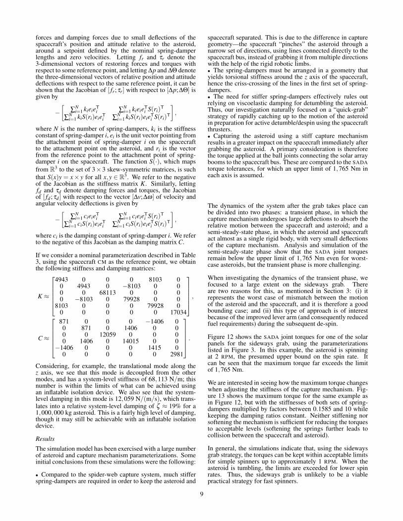
The dynamics of the system after the grab takes place canbe divided into two phases: a transient phase, in which thecapture mechanism undergoes large deflections to absorb therelative motion between the spacecraft and asteroid; and asemi-steady-state phase, in which the asteroid and spacecraftact almost as a single rigid body, with very small deflectionsof the capture mechanism. Analysis and simulation of thesemi-steady-state phase show that the SADA joint torquesremain below the upper limit of 1,765 Nm even for worst-case asteroids, but the transient phase is more challenging.
When investigating the dynamics of the transient phase, wefocused to a large extent on the sideways grab. Thereare two reasons for this, as mentioned in Section 3: (i) itrepresents the worst case of mismatch between the motionof the asteroid and the spacecraft, and it is therefore a goodbounding case; and (ii) this type of approach is of interestbecause of the improved lever arm (and consequently reducedfuel requirements) during the subsequent de-spin.
Figure 12 shows the SADA joint torques for one of the solarpanels for the sideways grab, using the parameterizationslisted in Figure 3. In this example, the asteroid is spinningat 2 RPM, the presumed upper bound on the spin rate. Itcan be seen that the maximum torque far exceeds the limitof 1,765 Nm.
We are interested in seeing how the maximum torque changeswhen adjusting the stiffness of the capture mechanism. Fig-ure 13 shows the maximum torque for the same example asin Figure 12, but with the stiffnesses of both sets of spring-dampers multiplied by factors between 0.1585 and 10 whilekeeping the damping ratios constant. Neither stiffening norsoftening the mechanism is sufficient for reducing the torquesto acceptable levels (softening the springs further leads tocollision between the spacecraft and asteroid).
In general, the simulations indicate that, using the sidewaysgrab strategy, the torques can be kept within acceptable limitsfor simple spinners up to approximately 1 RPM. When theasteroid is tumbling, the limits are exceeded for lower spinrates. Thus, the sideways grab is unlikely to be a viablepractical strategy for fast spinners.
9
0 50 100 150 200 250 300 350 400−4000
−3000
−2000
−1000
0
1000
2000
3000
4000
5000
6000
Time (hrs)
SA
DA
join
t tor
ques
(N
m)
xyz
Figure 12. SADA joint torques for panel 1 during sidewaysgrab at 2 RPM. The maximum torque far exceeds the limit of1,765 Nm.
0.25 0.5 1 2 4 80
2000
4000
6000
8000
10000
12000
14000
16000
18000
Stiffness multiplier
Max
SA
DA
join
t tor
que
(Nm
)
Figure 13. Max SADA joint torques for panel 1 for a rangeof stiffness multipliers
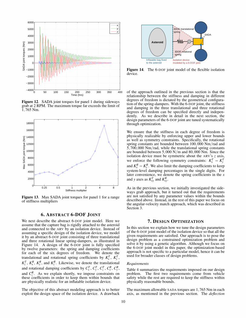
6. ABSTRACT 6-DOF JOINTWe next describe the abstract 6-DOF joint model. Here weassume that the capture bag is rigidly attached to the asteroidand connected to the ARV by an isolation device. Instead ofassuming a specific design of the isolation device, we modelit by an abstract 6-DOF joint consisting of three translationaland three rotational linear spring-dampers, as illustrated inFigure 14. A design of the 6-DOF joint is fully specifiedby twelve parameters: the spring and damping coefficientsfor each of the six degrees of freedom. We denote thetranslational and rotational spring coefficients by KT
x , KTy ,
KTz , KR
x , KRy , and KR
z . Likewise, we denote the translationaland rotational damping coefficients by CT
x , CTy , CT
z , CRx , CR
y ,and CR
z . As we explain shortly, we impose constraints onthese coefficients in order to keep them within bounds thatare physically realistic for an inflatable isolation device.
The objective of this abstract modeling approach is to betterexploit the design space of the isolation device. A drawback
Darts Lab Mobility & Robotic Systems - 347
Simulation Settings (Case 2)
4
Asteroid
Inflatable bag fixed
to the asteroid
3DOF translational
spring
3DOF rotational
spring
Isolation device
modeled by a 6-DOF joint
SADA
Figure 14. The 6-DOF joint model of the flexible isolationdevice.
of the approach outlined in the previous section is that therelationship between the stiffness and damping in differentdegrees of freedom is dictated by the geometrical configura-tion of the spring-dampers. With the 6-DOF joint, the stiffnessand damping in the three translational and three rotationaldegrees of freedom can be specified directly and indepen-dently. As we describe in detail in the next section, thedesign parameters of the 6-DOF joint are tuned systematicallythrough optimization.
We ensure that the stiffness in each degree of freedom isphysically realizable by enforcing upper and lower boundsas well as symmetry constraints. Specifically, the rotationalspring constants are bounded between 100,000 Nm/rad and5,700,000 Nm/rad, while the translational spring constantsare bounded between 5,000 N/m and 80,000 Nm. Since theisolation device must be symmetric about the ARV’s z axis,we enforce the following symmetry constraints: KT
x = KTy
and KRx = KR
y . We also limit the damping coefficients to keepsystem-level damping percentages in the single digits. Forlater convenience, we denote the spring coefficients in the xand y axes as KT
xy and KRxy.
As in the previous section, we initially investigated the side-ways grab approach, but it turned out that the requirementsare not satisfied by any parameter values within the boundsdescribed above. Instead, in the rest of this paper we focus onthe angular-velocity match approach, which was described inSection 3.
7. DESIGN OPTIMIZATIONIn this section we explain how we tune the design parametersof the 6-DOF joint model of the isolation device so that all thegiven requirements are satisfied. Our approach is to pose thedesign problem as a constrained optimization problem andsolve it by using a genetic algorithm. Although we focus onthe 6-DOF joint model in this paper, the optimization-basedapproach is not specific to a particular model, hence it can beused for broader classes of design problems.
Requirements
Table 4 summarizes the requirements imposed on our designproblem. The first two requirements come from vehiclesafety while the rest are required to keep the stiffness withinphysically reasonable bounds.
The maximum allowable SADA torques are 1,765 Nm in eachaxis, as mentioned in the previous section. The deflection
10

Optimization requirements
SymbolLowerbound
Upperbound Unit
SADA joint torques T SADAx,y,z - 1,765 Nm
Deflection angle θ - 45 deg
Lateral stroke lL - 1.0 m
Axial stroke lA - 2.0 m
Translational springcoefficients
KTxy,z 5,000 80,000 N/m
Rotational springcoefficients
KRxy 100,000 570,000 Nm/rad
KRz 100,000 5,700,000 Nm/rad
Table 4.
Deflection angle
(a) Deflection angle
Lateral stroke
Axial stroke
(b) Lateral and axial strokes
Figure 15. Definitions of optimization metrics
angle of the ARV, which is illustrated in Figure 15(a), isdefined as the angle of rotation between the spacecraft andasteroid, with zero rotation defined by the relative attitudeat the start of the capture. The deflection angle must belimited to 45◦ in order to ensure adequate clearance with theasteroid. The lateral and axial strokes are the deflections ofthe translational spring in the 6-DOF joint model in lateral(i.e., x and y) and axial (i.e., z) directions, respectively, asshown in Figure 15(b). We constrain the lateral stroke to 1 mand the axial stroke to 2 m. We denote the SADA torque,the deflection angle, the lateral stroke, and the axial stroke attime t by T SADA
i (t), θ(t), lT (t), and lA(t), respectively, wherei = x,y,z. As we discussed in the previous section, we imposeupper and lower bounds on the structural spring coefficientsfor the sake of physical realizability, as shown in the table.
Throughout the rest of the paper we denote by · and · theupper and lower bounds of a variable.
We consider asteroids with initial spin rates of up to 2 RPMand mass of up to 1,000,000 kg. Within this range, therequirements specified above must be robustly satisfied forall possible moments of inertia and spin states.
Optimization Problem Formulation
Given the requirements specified above, we next formulatea constrained optimization problem that is solved to obtaina feasible set of design parameters. In particular, we posethe optimization problem as a minimization of the deflectionangle with constraints on SADA torques, lateral and axial
strokes, and spring coefficients, as follows:
minmaxt
θ(t)
over
KTi ≤ KT
i ≤ KTi , KR
i ≤ KRi ≤ KR
i , i = xy,z
subject to
maxt
T SADAi (t)≤ T SADA
i , i = x,y,z
maxt
lT (t)≤ lT , maxt
lA(t)≤ lA
Note that θ , T SADA, lT , and lA are time-varying variables.Therefore, their maximum over time must be below thespecified upper bound. Also note that we minimize themaximum deflection angle, maxt θ(t), instead of imposing ahard constraint on it. After solving the optimization problem,we check if the resulting maximum deflection angle is belowthe specified upper bound. If not, the design problem isinfeasible.
The optimization problem can be formulated in other ways,for example, a minimization of one of the SADA joint torqueswhile imposing constraints on the other SADA torques andthe deflection angle. In general, the objective function shouldreflect the preference among feasible solutions. We chosethe deflection angle as the objective function because it isconsidered to be preferable to have smaller deflection anglein order to minimize the risk of total loss of the ARV due toa collision with the asteroid. It is also possible to employa more complicated preference metric consisting of multiplevariables.
Evaluation of Objective and Constraint Functions usingDarts/Dshell
We use Darts/Dshell in order to evaluate θ(t), T SADAi (t), lA(t),
and lT (t) in the optimization problem formulated above. Wecreate physics models of the ARV and an asteroid, whosephysical properties are specified by adjustable parameters.
As described in the previous section, we need to evaluate themaximum of the objective and constraint functions over time.Therefore, we must fully simulate the transient response,which starts at the time of contact between the capture deviceof the ARV and the asteroid and typically lasts for ∼ 100 s.This simulation must be performed at each iteration of theoptimization. Its typical running time is 5–10 s.
Optimization Method
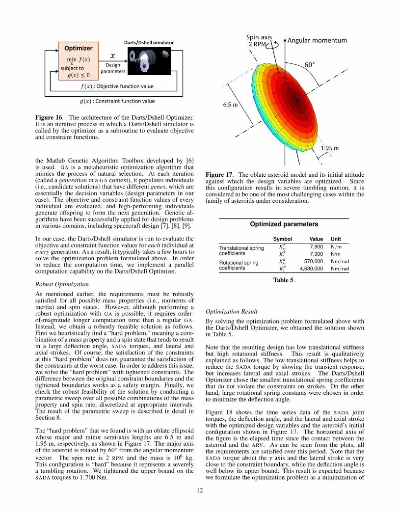
Building upon Darts/Dshell, we have recently developedthe Darts/Dshell Optimizer that is capable of solving theoptimization problem formulated above. Figure 16 showsthe block diagram of our iterative optimization system. Anoptimization algorithm specifies a set of design parameters,which in our case include spring coefficients. Then theDarts/Dshell simulator is called as a subroutine that takesthe design parameters as inputs and outputs the objectiveand constraint function values (i.e., θ(t), T SADA
i (t), lA(t), andlT (t)). The optimization algorithm takes them as inputs, anduse the inputs to adjust the design parameters in order to re-fine the solution. This iteration is repeated until convergenceto an optimal solution. It can handle both constrained andunconstrained optimizations.
We employ a genetic algorithm (GA) [5] to implement theDarts/Dshell Optimizer. A third-party implementation called
11
Optimizer
min 𝑓(𝑥) subject to
𝑔 𝑥 ≤ 0
𝑥 Design
parameters
𝑓(𝑥) : Objective function value
𝑔(𝑥) : Constraint function value
Darts/Dshell simulator
Figure 16. The architecture of the Darts/Dshell Optimizer.It is an iterative process in which a Darts/Dshell simulator iscalled by the optimizer as a subroutine to evaluate objectiveand constraint functions.
the Matlab Genetic Algorithm Toolbox developed by [6]is used. GA is a metaheuristic optimization algorithm thatmimics the process of natural selection. At each iteration(called a generation in a GA context), it populates individuals(i.e., candidate solutions) that have different genes, which areessentially the decision variables (design parameters in ourcase). The objective and constraint function values of everyindividual are evaluated, and high-performing individualsgenerate offspring to form the next generation. Genetic al-gorithms have been successfully applied for design problemsin various domains, including spacecraft design [7], [8], [9].
In our case, the Darts/Dshell simulator is run to evaluate theobjective and constraint function values for each individual atevery generation. As a result, it typically takes a few hours tosolve the optimization problem formulated above. In orderto reduce the computation time, we implement a parallelcomputation capability on the Darts/Dshell Optimizer.
Robust Optimization
As mentioned earlier, the requirements must be robustlysatisfied for all possible mass properties (i.e., moments ofinertia) and spin states. However, although performing arobust optimization with GA is possible, it requires order-of-magnitude longer computation time than a regular GA.Instead, we obtain a robustly feasible solution as follows.First we heuristically find a “hard problem,” meaning a com-bination of a mass property and a spin state that tends to resultin a large deflection angle, SADA torques, and lateral andaxial strokes. Of course, the satisfaction of the constraintsat this “hard problem” does not guarantee the satisfaction ofthe constraints at the worst case. In order to address this issue,we solve the “hard problem” with tightened constraints. Thedifference between the original constraint boundaries and thetightened boundaries works as a safety margin. Finally, wecheck the robust feasibility of the solution by conducting aparametric sweep over all possible combinations of the massproperty and spin rate, discretized at appropriate intervals.The result of the parametric sweep is described in detail inSection 8.
The “hard problem” that we found is with an oblate ellipsoidwhose major and minor semi-axis lengths are 6.5 m and1.95 m, respectively, as shown in Figure 17. The major axisof the asteroid is rotated by 60◦ from the angular momentumvector. The spin rate is 2 RPM and the mass is 106 kg.This configuration is “hard” because it represents a severelya tumbling rotation. We tightened the upper bound on theSADA torques to 1,700 Nm.
2 RPM Spin axis
6.5 m
1.95 m
60∘
Angular momentum
Figure 17. The oblate asteroid model and its initial attitudeagainst which the design variables are optimized. Sincethis configuration results in severe tumbling motion, it isconsidered to be one of the most challenging cases within thefamily of asteroids under consideration.
Optimized parameters
Symbol Value Unit
Translational springcoefficients
KTxy 7,900 N/m
KTz 7,300 N/m
Rotational springcoefficients
KRxy 570,000 Nm/rad
KRz 4,630,000 Nm/rad
Table 5.
Optimization Result
By solving the optimization problem formulated above withthe Darts/Dshell Optimizer, we obtained the solution shownin Table 5.
Note that the resulting design has low translational stiffnessbut high rotational stiffness. This result is qualitativelyexplained as follows. The low translational stiffness helps toreduce the SADA torque by slowing the transient response,but increases lateral and axial strokes. The Darts/DshellOptimizer chose the smallest translational spring coefficientsthat do not violate the constraints on strokes. On the otherhand, large rotational spring constants were chosen in orderto minimize the deflection angle.
Figure 18 shows the time series data of the SADA jointtorques, the deflection angle, and the lateral and axial strokewith the optimized design variables and the asteroid’s initialconfiguration shown in Figure 17. The horizontal axis ofthe figure is the elapsed time since the contact between theasteroid and the ARV. As can be seen from the plots, allthe requirements are satisfied over this period. Note that theSADA torque about the y axis and the lateral stroke is veryclose to the constraint boundary, while the deflection angle iswell below its upper bound. This result is expected becausewe formulate the optimization problem as a minimization of
12

deflection angle with hard constraints on the SADA torquesand the strokes. Irregular transient responses are observedfor approximately 50 s after the contact. Then follows anoscillatory behavior with approximately 80-s period.
0 50 100 150 200 250 3000
500
1000
1500
2000
Time [s]
Tor
que
[Nm
]
XYZ
(a) SADA joint torques (absolute values)
0 50 100 150 200 250 3000
0.5
1
1.5
2
2.5
Time [s]
Def
lect
ion
angl
e [d
eg]
(b) Deflection angle
0 50 100 150 200 250 3000
0.5
1
1.5
Time [s]
Spr
ing
defle
ctio
n [m
]
LateralAxial
(c) Lateral and axial strokes (absolute values)
Figure 18. The time-series plots of the SADA torques,deflection angle, and spring deflections
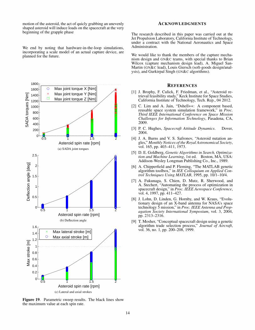
8. PARAMETRIC SWEEPSIn this section we perform a parametric sweep over the massproperties and the spin state of the asteroid in order to verifythat the solution obtained in the previous section robustlysatisfies the given requirements.
By mass property we mean the mass and the moments ofinertia of the asteroid. We assume that the mass is at the upperbound, 1,000,000 kg. Without loss of generality we assumethat the principal axes correspond to the x, y, and z axes ofthe asteroid’s body frame. The ARV’s dynamic behavior isinfluenced by the asteroid’s mass, moments of inertia, andspin state, but not its shape. Therefore we assume withoutloss of generality that the asteroid is a solid ellipsoid. Itsmoments of inertia is fully specified by the length of its threesemi-axes, which are denoted by rx, ry, and rz. We assumerx ≥ ry ≥ rz and fix rx to its upper bound, 6.5 m. We letry = kyrx and rz = kzrx, and we vary ky and kz within a range0.3≤ ky ≤ kz ≤ 1 with an interval of 0.1.
As for the spin state, we assume that the angular velocity isaligned with the z axis of the inertial frame. We specify theinitial attitude of the asteroid by Euler angles relative to theinertial frame, denoted by α (about the x axis), β (y axis), andγ (z axis). We sweep over 38 initial attitudes, 19 of which arewith β = γ = 0 and α = 0,5◦,10◦, . . . ,90◦ while the othersare with α = γ = 0 and β = 0,5◦,10◦, . . . ,90◦. The spin rateis varied from 0.5 RPM to 2 RPM with an interval of 0.5 RPM.This results in 5,472 combinations in total.
Figure 19 shows the result of the parametric sweep. In all the5,472 cases, the requirements are fully satisfied.
9. CONCLUDING REMARKSThe results of Section 8 suggest that, with a properly designedcapture mechanism, it is indeed possible to handle the rangeof asteroids baselined for this study without giving rise toexcessive loads on critical spacecraft components. Figure19 does indicate that the SADA torque margins are relativelysmall; however, as explained in Section 7, the capture mech-anism parameters were not chosen to minimize the torques,but to minimize the deflection angle subject to the torqueconstraint. Moreover, some of the worst-case scenarios maybe considered unlikely enough to be excluded from futureconsideration. The asteroids resulting in the highest SADAtorques tend to have the following characteristics:
• High spin rate• Oblate shape• Inertially axi-symmetrical mass geometry• Large aspect ratio• Large nutation angle (i.e., far from major-axis spin)
Clearly, many aspects of the capture problem are not reflectedin the current simulation model. Some of the topics to beaddressed in future work include the following:
• Design realizability. Although the design optimization wascarried out with realistic bounds on stiffness and dampingparameters, the parameters for each degree of freedom werechosen independently. For a given passive mechanical sys-tem, additional constraints will inevitably exist between thevarious degrees of freedom; these can be taken into accountby introducing additional constraints in the optimizationproblem.• Precision of angular velocity match. For the results in Sec-tion 8, it was assumed that the capture mechanism attaches tothe asteroid instantaneously, at the moment when the angularvelocity of the spacecraft is precisely matched with that ofthe asteroid. In reality, the capture will not be instantaneous,and there will be some residual relative motion between theasteroid and the spacecraft.• Settling dynamics. In addition to the loads caused by the
13
motion of the asteroid, the act of quicly grabbing an unevenlyshaped asteroid will induce loads on the spacecraft at the verybeginning of the grapple phase
We end by noting that hardware-in-the-loop simulations,incorporating a scale model of an actual capture device, areplanned for the future.
0.5 1 1.5 20
200
400
600
800
1000
1200
1400
1600
1800
Asteroid spin rate [rpm]
SA
DA
torq
ues
[Nm
]
Max joint torque X [Nm]Max joint torque Y [Nm]Max joint torque Z [Nm]
(a) SADA joint torques
0.5 1 1.5 20
0.5
1
1.5
2
2.5
Asteroid spin rate [rpm]
Def
lect
ion
angl
e [d
eg]
(b) Deflection angle
0.5 1 1.5 20
0.2
0.4
0.6
0.8
1
1.2
1.4
1.6
Asteroid spin rate [rpm]
Max
str
oke
[m]
Max lateral stroke [m]Max axial stroke [m]
(c) Lateral and axial strokes
Figure 19. Parametric sweep results. The black lines showthe maximum value at each spin rate.
ACKNOWLEDGMENTS
The research described in this paper was carried out at theJet Propulsion Laboratory, California Institute of Technology,under a contract with the National Aeronautics and SpaceAdministration.
We would like to thank the members of the capture mecha-nism design and GN&C teams, with special thanks to BrianWilcox (capture mechanism design lead), A. Miguel San-Martin (GN&C lead), Louis Giersch (soft-goods design/anal-ysis), and Gurkirpal Singh (GN&C algorithms).
REFERENCES[1] J. Brophy, F. Culick, F. Friedman, et al., “Asteroid re-
trieval feasibility study,” Keck Institute for Space Studies,California Institute of Technology, Tech. Rep., 04 2012.
[2] C. Lim and A. Jain, “Dshell++: A component based,reusable space system simulation framework,” in Proc.Third IEEE International Conference on Space MissionChallenges for Information Technology, Pasadena, CA,2009.
[3] P. C. Hughes, Spacecraft Attitude Dynamics. Dover,2004.
[4] J. A. Burns and V. S. Safronov, “Asteroid nutation an-gles,” Monthly Notices of the Royal Astronomical Society,vol. 165, pp. 403–411, 1973.
[5] D. E. Goldberg, Genetic Algorithms in Search, Optimiza-tion and Machine Learning, 1st ed. Boston, MA, USA:Addison-Wesley Longman Publishing Co., Inc., 1989.
[6] A. Chipperfield and P. Fleming, “The MATLAB geneticalgorithm toolbox,” in IEE Colloquium on Applied Con-trol Techniques Using MATLAB, 1995, pp. 10/1–10/4.
[7] A. Fukunaga, S. Chien, D. Mutz, R. Sherwood, andA. Stechert, “Automating the process of optimization inspacecraft design,” in Proc. IEEE Aerospace Conference,vol. 4, 1997, pp. 411–427.
[8] J. Lohn, D. Linden, G. Hornby, and W. Kraus, “Evolu-tionary design of an X-band antenna for NASA’s spacetechnology 5 mission,” in Proc. IEEE Antenna and Prop-agation Society International Symposium, vol. 3, 2004,pp. 2313–2316.
[9] T. Mosher, “Conceptual spacecraft design using a geneticalgorithm trade selection process,” Journal of Aircraft,vol. 36, no. 1, pp. 200–208, 1999.
14


![Milestone Edge Storage With Flexible Retrieval[1]](https://img.pdfslide.net/doc/110x75/55cf8f8f550346703b9d7781/milestone-edge-storage-with-flexible-retrieval1.jpg)