Embed Size (px)
Citation preview

� � � � � � � � � � � � � � �
Modeling and Simulation of the Operation of a
Rotary Magnetic Refrigerator
�
Didier VUARNOZ* Andrej KITANOVSKI
** Cyrill GONIN
** �
Peter W. EGOLF**
Tsuyoshi KAWANAMI *
*Department of Mechanical Engineering, Graduate School of Engineering, Kobe University
(1-1 Rokkodai-cho, Nada-ku, Kobe, 657-8501, Japan)
**Institute of Thermal Sciences and Engineering IGT, University of Applied Sciences of Western Switzerland
(Route de Cheseaux 1, 1401 Yverdon-les-Bains, Switzerland)
Summary
� Magnetic refrigeration is a new environmentally benign technology and a promising alternative to conventional
vapor-cycle refrigeration. The household refrigerator without a freezing compartment shows very good prospects
for a successful application. This article starts with the general principle of magnetic refrigeration. An example of a
magnet assembly is proposed and the corresponding magnetic flux lines are evaluated with a three-dimensional
finite-element method (FEM). The maximum specific cooling capacity of magneto caloric materials is described.
The specific cooling power of a magneto caloric material is found to be large even for medium magnetic field
changes, especially if the frequency is not too small. For a domestic magnetic refrigerator, a comparison with a
standard compressor refrigerator is presented. The modeling of a rotary magnetic refrigerator is described and its
dynamic behavior is investigated. The physical model is based on a mapping of the magneto-thermodynamic prob-
lem from a cylinder onto two rectangles. In this model, in a basic centre cell, two coupled linear partial differential
equations are solved, which have been programmed in the Modelica language. Steady-state solutions are envisaged
to determine the coefficient of performance, COP, for these conditions. In future work the developed model shall
be applied for an optimization of the magnetic refrigerator and to determine the related best parameters.
Key words: Magnetic refrigerator, Modeling, Simulation, Magneto caloric effect.
1. Introduction
In 1881 Emil Gabriel Warburg (1846-1931) dis-
covered the magneto caloric effect in an iron sample.
It heated a few Millikelvin when moved into a ma-
gnetic field and cooled down again when it was re-
moved out of the field (Warburg, 1881).
�
This technology was successfully applied in low
temperature physics since the 1930’s to cool down
samples from a few Kelvin to a few hundreds of a
Kelvin above the absolute zero point (-273.15 K).
The 5th Asian Conference on Refrigeration and Air Conditioning
Proceedings of 5th ACRA
June 7-9, 2010, Tokyo, JAPAN
Paper No. 029

A milestone - almost comparable to the discovery
of the magneto caloric effect by Warburg - was in
1997 the discovery of the «giant» magneto caloric
effect (Pecharsky and Gschneidner, 1997a). This
publication and some following one's by these au-
thors (Pecharsky and Gschneidner, 1997b) and also
of Tegus et al. (2002), are responsible that since the
beginning of this millennium magnetic refrigeration
started to reveal a realistic potential for commercial
room temperature applications at least for certain
suitable market segments.
Nowadays the literature on the field consists of a
majority of studies dealing with the magneto caloric
effect (MCE) in materials. Also an increasing num-
ber of articles treat thermo-magnetic machine design
and calculation, and a somewhat smaller number de-
scribes theoretical and numerical simulation work
(see e.g. Kitanovski et al. (2005) and Šarlah et al.
(2007).
For example, a thermodynamic model and related
numerical simulations of the behavior of a machine
with a magneto caloric wheel have been worked out
by Egolf et al. (2006). Temperature mappings are
obtained for both, material and fluid components of
the rotor. Engelbrecht et al. (2007) used a NTU
method to elaborate a full model on the prototype
being a liquid AMRR system, with a particle bed
built by the Astronautics Corporation of America.
They compared the simulation results with experi-
mental data of Zimm et al. (2007). An over pre-
diction of loss is shown at low ratio of the thermal
capacity of the flowing fluid to the thermal capacity
of the matrix. A 1-d “dynamical model” of an active
magnetic regenerator has been proposed with the
purpose to make a parametric investigation (Tagliafi-
co et al. 2009). It was found that parameters could
be tuned to obtain an optimal behavior for a given
span of the investigated system.
2. Magnetic refrigerator
Rotary magnetic machines work like rotary heat
recovery machines applied with success for decades
in air conditioning.
A first step is the magnetization of a porous solid
magneto caloric structure in a magnetic field, follo-
wed by a simultaneous heating-up of the material.
By a fluid flow this structure is cooled, and after that
it turns out of the magnetic field and shows a de-
magnetization process. Here the magneto caloric al-
loy becomes cold and is heated by a fluid, which
preferable has the opposite flow direction to the first
flow. If the hot fluid on one side is used, it’s a heat
pump application; if the cold fluid is applied then the
machine is a cooler or a refrigerator.
In Figure 1 a magnetic assembly with a porous
magneto caloric wheel containing two regions of in-
tense magnetic field and two regions of low mag-
netic field is presented.
Figure 1: A conceptual drawing of an axial magnetic
refrigerator is shown. It contains standard NdFeB
magnets (denoted by A) and auxiliary elements for a
convenient conduction of the magnetic flux (ferroco-
balt, denoted by B) and the turning magneto caloric
ring denoted by C (from Swinnen, 2009).
Results of a three-dimensional finite-element nu-
merical simulation, obtained with the ANSYS soft-
ware, of the magnetic flux density in the magnetic
assembly (shown in Figure 1) are shown in Figure 2.

Figure 2: The magnetic field strength distribution in
the unit of an induction (Tesla) is shown. The results
have been taken from Swinnen, 2009.
3. The theoretical maximum specific
cooling power
Essential information for a design and analysis
of a magnetic refrigerator is the cooling capacity of
the magneto caloric material. The maximum specific
cooling energy of a magneto caloric material (see
Figure 3) is directly related to the entropy and tem-
perature change, which occurs due to a magneti-
zation/demagnetization of the magneto caloric mate-
rial. To obtain a maximum cooling capacity, a well-
defined domain around the Curie temperature TC has
to be taken into consideration.
The maximum specific cooling energy of a single
material is obtained by an isothermal demagnetiza-
tion at Curie temperature (see Eq. (1)), while the ma-
ximum temperature change is obtained by an adiaba-
tic magnetization also at Curie temperature:
(1)
The Δs(TC) presents the total entropy change at
Curie temperature. The maximum specific cooling
energy is obtained only with cycles, as e.g. the Erics-
son (two isomagnetic field processes, two isothermal
processes) or the Stirling (two isomagnetic field pro-
cesses, two isothermal processes) by also applying a
regenerative process. The Carnot cycle cannot per-
form a so large specific cooling energy compared to
the two above described cycles. The same is valid
for the Brayton cycle (two isomagnetic field pro-
cesses, two isentropic processes).
Figure 3: Theoretical maximum specific cooling
energy as a result of the isothermal demagnetization
process for the rare earth gadolinium is shown in a
shaded area (from Egolf et al, 2008).
With the frequency of a machine it is possible to
define the theoretical maximum specific cooling
power as follows:
(2)
The specific cooling power of magneto caloric
material may be large even for low magnetic field
changes (see Figure 4). However, high frequencies
require a fast convective and diffusive heat transfer
process. Convective transport is dependent on the
fluid flow characteristics as well as on the geometry
of the magneto caloric structure. Diffusion does not

present a serious limitation, if small structured mag-
neto caloric material is applied, because the diffu-
sion transport time decreases with the second power
of the transport length (Egolf et al., 2006).
Figure 4: The theoretical maximum specific cooling
power for gadolinium as a function of the magnetic
field strength variation and the frequency of ope-
ration (from Kitanovski and Egolf, 2009).
The fluid friction losses rapidly increase with the
frequency of operation, because a characteristic
transport time of a fluid lump through the material
bed has to be much smaller than the period of rota-
tion. Because small magnetic field changes cause
small temperature differences in the material, the
magnetic refrigerator usually must operate with a re-
generative cycle (or a cascade system). This leads to
additional irreversibility’s due to the larger number
of occurring heat transfer processes and related fluid
friction losses. Therefore, it is a wrong opinion that
small magnetic fields with high frequencies may be
equivalent to high magnetic fields with low frequen-
cies in order to obtain the same temperature span
and keeping the same efficiency of a magnetic refri-
gerator.
Figure 5 shows the comparison of the COP of a
rotary magnetic household refrigerator (magnetic
flux density 2 Tesla) with one containing a hermetic
compressor. The heat source temperature is identical
to the evaporation temperature of the refrigerant.
The thick line corresponds to the COP of a Danfoss
hermetic compressor (LBP/ MBP and MBP/HBP,
R404a/R507, type FR 6CL) with a condensing tem-
perature at 45 °C.
These results show that the frequency of operation
depends on the characteristics of a magnetic refrige-
rator. The reason for this is that a higher velocity of
the working fluid leads to a higher-pressure drop and,
therefore, also to higher irreversibility’s.
Figure 5: The COP of a magnetic household refrige-
rator as a function of the heat source temperature
and the frequency of operation for a magnetic flux
density change of 2 Tesla is shown (from Kitanovski
et al., 2008). The sink temperature has been fixed at
45 °C. The porosity of the magneto caloric wheel is
10 %.
Figure 5 shows that a magnetic household refrige-
rator is competitive to one containing a compressor.
This is especially the case when the frequency is low,
e.g. below 5 Hz; however, for a high magnetic flux
density change the frequency may be higher. This
leads to a smaller mass and volume of the device,
which is very essential mainly because of economic
reasons.
4. Physical modeling of
the magneto caloric generator
The physical modeling of a rotating porous rotor
made of magneto caloric material is described in de-
tail in an earlier article by Kitanovski et al. (2005). It

is based on two main simplifying assumptions:
1) The rotation frequency f of the ring is low
compared to the inverse characteristic time of resi-
dence of a fluid lump flowing vertically or horizon-
tally through the porous structure.
2) The heat conduction through the rotor in
axial direction is negligible compared to the heat
flux by convection.
The magneto caloric porous ring has been divided
into two principal kinds of cells, as it is shown in
Figure 6.
Figure 6: The main center part of a magnetic cooling
machine consists of a rotating porous magneto calo-
ric ring. The half top section is in a magnetic field
and the half lower section is the zero-field region. In
our case two heat transfer fluids flow in opposite
axial direction through each of these regions. To
show the decomposition of the magneto caloric ring
into cells is the main purpose of this figure.
4.1 Basic cells
Basic cells represent physically the part of the
magneto caloric rotor and describe the heat transfer
by conduction of magneto caloric material and the
heat transfer from the fluid to the magneto caloric
wheel. Deriving two times two coupled partial diffe-
rential equations, which are referred to in detail in
Kitanovski et al. (2005), lead to the following well-
conditioned algorithms (3) and (4) for the centre
cells:
(3)
(4)
T denotes the temperature and the index F the
Fluid and R the Rotor matrix. The fluid temperature
is handed over from an inlet to an outlet in horizon-
tal direction and the rotor temperature identical in
the vertical direction. The quantities χF and χR con-
tain all physical properties of the fluid and the rotor
material, respectively, and the heat transfer coeffi-
cients. They are defined in equation (5) and (6) as:
(5)
(6)
Δφ and Δz denote the differences in the azimuth
and in the axial direction, respectively.
4.2 Border Cells
The virtual elements, describing in time changing
sections of the wheel, are related to real physical
parts (2-d plans are drawn for their representation
(see e.g. in Figure 6)). In the border cells the rever-
sible adiabatic temperature transitions, induced by
the alternating magnetic field in the rotor structure,
were implemented. The adiabatic temperature chan-
ge, as a function of the magneto caloric material
temperature and the magnetic field change, was
determined by mean field theory calculations.
4.3 Programming a Full System
The chosen object-orientated language is Mo-
delica 2.2.1 with the commercialized interface Dy-
mola 6.1. A full description of the computation work
can be found in Vuarnoz et al. (2009). The assembly
of home-made cells (basic cells, border cells)
together with numerous standard modules, e.g. for
pumps, heat sources and flowPorts, from the thermal
“FluidHeatFlow” library, can be assembled to obtain
a magneto caloric generator module. As an example,
a refrigerator with two magneto caloric generators
coupled in a cascade – as shown in Figure 7 – is at
present investigated.
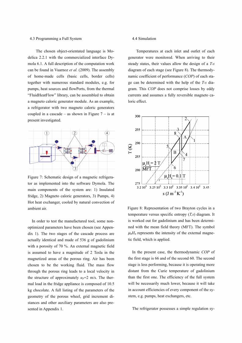
Figure 7: Schematic design of a magnetic refrigera-
tor as implemented into the software Dymola. The
main components of the system are: 1) Insulated
fridge, 2) Magneto caloric generators, 3) Pumps, 4)
Hot heat exchanger, cooled by natural convection of
ambient air.
In order to test the manufactured tool, some non-
optimized parameters have been chosen (see Appen-
dix 1). The two stages of the cascade process are
actually identical and made of 536 g of gadolinium
with a porosity of 70 %. An external magnetic field
is assumed to have a magnitude of 2 Tesla in the
magnetized areas of the porous ring. Air has been
chosen to be the working fluid. The mass flow
through the porous ring leads to a local velocity in
the structure of approximately uF=2 m/s. The ther-
mal load in the fridge appliance is composed of 10.5
kg chocolate. A full listing of the parameters of the
geometry of the porous wheel, grid increment di-
stances and other auxiliary parameters are also pre-
sented in Appendix 1.
4.4 Simulation
Temperatures at each inlet and outlet of each
generator were monitored. When arriving to their
steady states, their values allow the design of a T-s
diagram of each stage (see Figure 8). The thermody-
namic coefficient of performance (COP) of each sta-
ge can be determined with the help of the T-s dia-
gram. This COP does not comprise losses by eddy
currents and assumes a fully reversible magneto ca-
loric effect.
Figure 8: Representation of two Brayton cycles in a
temperature versus specific entropy (T,s) diagram. It
is worked out for gadolinium and has been determi-
ned with the mean field theory (MFT). The symbol
µ0H0 represents the intensity of the external magne-
tic field, which is applied.
In the present case, the thermodynamic COP of
the first stage is 66 and of the second 60. The second
stage is less performing, because it is operating more
distant from the Curie temperature of gadolinium
than the first one. The efficiency of the full system
will be necessarily much lower, because it will take
in account efficiencies of every component of the sy-
stem, e.g. pumps, heat exchangers, etc.
The refrigerator possesses a simple regulation sy-

stem, which guarantees a certain stability of the in-
side air temperature by an alternating sequence of an
“ON” and “OFF” mode, as it is shown in Figure 9.
The investigated refrigeration unit with a two-step
cascade working with a mass of totally 536 g of Gd
cools 10.5 kg chocolate 7 K in approximately 14
hours.
Figure 9: Time evolution of the temperature of the
working fluid at the inlet and outlet of the magnetic
refrigerator appliance modeled according to the
schematic drawing shown in Figure 7. The inlet tem-
perature evolution of the air in the cabinet during the
“OFF” mode shows the typical exponential decay as
it is expected to occur in such a thermodynamic ma-
chine with a thermal inertia and heat transfer losses.
A perfect heat transfer is assumed to occur between
the charge and the air in the refrigerator. The inside
temperature of the appliance is identical to the one
of the air flowing out of the equipment. The refrige-
rator is assumed to have a standard insulation and no
door openings were taken into consideration. The
time to reach the steady-state temperature is rather
large. The reason is that the thermal charge in the ap-
pliance is not in accordance with the mass of the
magneto caloric material. However the simulation
results are showing the potential of such a developed
tool for a parameter study and optimization process.
Another kind of system, e.g. regenerative system
(see Figure 10) can now easily be implemented for a
similar analysis.
Figure 10: A schematic sketch shows how a three-
stage magnetic household refrigerator could be de-
signed. The three red/blue rotor wheels are connec-
ted to perform regeneration cycles. Notify that the
design may permit to only have two pumps in such a
multi-stage machine.
5. Conclusions
In this article magnetic refrigeration is described
and a rotary system is investigated. The maximum
specific cooling energy that can be extracted from
magneto caloric material has been determined. The
household refrigerator without a freezing compart-
ment is showing very good prospects for a success-
ful application.
A numerical tool to optimize magnetic refrigera-
tors is presented. It contains a user-friendly commer-
cialized interface Dymola, where by drag and drop
methods a refrigerator can be easily built together
and modified. Programming in this modern software
is performed by the application of the object-orien-
ted language Modelica. The parameters have not yet
been determined by solving the numerical method
“Optimization Problem”, where the parameters are
determined in such a manner that a final quantity is
optimized. Based on the calculation results, the mag-
neto thermodynamic T-s diagram containing the
T (
K)

cycles of the two stages could be reconstructed. Fur-
ther improvements and the optimizations of this and
similar machines are at present under performance.
Acknowledgements
The authors are grateful to the Swiss Federal
Office of Energy (Thomas Kopp and Roland
Brüniger) for its financial support. We are grateful to
the Gebert Rüf Stiftung and the Hes-so foundation
for continuous interest in our work.
References
1) Warburg E.: Ann. Phys., vol. 13, p.141–164
(1881).
2) Pecharsky V.K., Gschneidner K.A. Jr.: “Giant
magnetocaloric effect in Gd5(Si2Ge2)”, Phys.
Rev. Lett. 78 (23) pp. 4494-4497 (1997a).
3) Pecharsky V.K., Gschneidner K.A., Jr.: “Effect of
alloying on the giant magneto caloric effect of
Gd5(Si2Ge2)”, J. Magn. Magn. Mater. 167, pp.
L179-L184 (1997b).
4) Tegus O., Brück E., Buschov K.H.J. De Boer
F.R.: “Transitional-metal-based magnetic refrige-
rants for room-temperature applications”, Nature
415, pp. 150-152 (2002).
5) Kitanovski A., Egolf P.W., Gendre F., Sari O.,
Besson Ch.: “A rotary heat exchanger magnetic
refrigerator”. Proceedings of the First Int. Conf.
on Magnetic Refrigeration at Room Temperature,
(Editor P.W. Egolf), ISBN 2-913149-41-3, Mon-
treux, Switzerland, pp. 297-307 (2005).
6) Šarlah A., Poredos A.: “Dimensionless numerical
model for determination of magnetic regenera-
tor’s heat transfer coefficient and its operation”.
Proceeding of the Second Int. Conf. on Magnetic
Refrigeration at Room Temperature, (Editor A.
Poredos), ISBN 978-2-913149-56-4, Portoroz,
Slovenia, pp. 419-426 (2007).
7) Egolf P.W., Sari O., Gendre F.: “Close- to-Car-
not-cycle magnetic refrigerators and heat pumps:
Analytical machine design and optimization”.
Proceedings of the Jubilee XX NMMM (New
Magnetic Materials of Microelectronics) Confe-
rence, Russian Ass. of Mag., Lomonosov State
University, Moscow, 12-16. June, AII-02 (2006).
8) Engelbrecht K.L., Nellis G.F., Klein S.A.: “Com-
paring modeling predictions to experimental data
for AMRR systems”. Proceeding of the Second
Int. Conf. on Magnetic Refrigeration at Room
Temperature, (Editor A. Poredos), ISBN 978-2-
913149-56-4, Portoroz, Slovenia, pp 349-357
(2007).
9) Zimm C., Auringer J., Boeder A., Chell J. Russek
S., Sternberg A.: “Design and initial performance
of a magnetic refrigerator with a rotating perma-
nent magnet”. Proceeding of the Second Int.
Conf. on Magnetic Refrigeration at Room Tem-
perature, (Editor A. Poredos), ISBN 978-2-
913149-56-4, Portoroz, Slovenia, pp 341-347
(2007).
10) Tagliafico G., Scarpa F., Tagliafico L,A.: “Dy-
namic 1D model of an active magnetic regene-
rator: a parametric investigation”, Proceeding of
the Third Int. Conf. on Magnetic Refrigeration at
Room Temperature, (Editor P.W. Egolf), ISBN
978-2-913149-67-0, Des Moines, USA (2009).
11) Swinnen T.: “Magnetic refrigeration: Theory and
simulation with C++ and ANSYS”, Bachelor the-
sis, University of Applied Sciences of Western
Switzerland (2009).
12) Egolf P.W., Kitanovski A., Gonin C., Diebold
M., Vuarnoz D.: ”Magnetic heating, refrigeration
and power conversion”, Proceeding of the 12th
Int. Conf. on Refrigeration and Air Conditioning,
paper ID 2298, Purdue, USA, (2008).
13) Egolf P.W., Gendre F., Kitanovski A., Sari O.:
“Machbarkeitsstudie für magnetische Wärme-
pumpen: Anwendungen in der Schweiz”,
Schlussbericht des Projektes zuhanden des Bun-
desamtes für Energie Nr.151017 (2006).
14) Kitanovski A., Vuarnoz D., Diebold M., Gonin
C., Egolf P.W.: “Application of magnetic refrige-
ration and its assessment”, Final Report of Pro-
ject No. 152 191, Swiss Federal Office of Energy
(2008).
15) Vuarnoz D., Kitanovski A., Gonin C., Sari O.,

Egolf P.W.: “Modeling of a two-stage magnetic
refrigerator with wavy-structured gadolinium
heat exchangers”. Int. J. Refrig. 33, 745-752
(2010).
Nomenclature
B Magnetic field induction (T)
c Specific heat capacity (J kg-1
K-1
)
CUP Chocolate Unit Plate, equiv. 100 g
d Diameter (m)
f Frequency (s-1
)
L Length (m)
m Mass (kg)
p Pressure (Pa)
s Specific entropy (J m-3
K-1
)
T Temperature (K)
v Velocity (m s-1
)
z Length (m)
Subscript
ad Adiabatic
F Fluid
H Constant magnetic field
h Hydraulic
in Inlet
out Outlet
R Rotor
Greek
α Heat transfer coeff. (W m-2
K-1
)
δ Characteristic geom. quantity (m)
Δ Difference
ξ Characteristic geom. quantity
ρ Density (kg m-3
)
υ Kinematic viscosity (m2 s
-1)
φ Angle (°)
χ Characteristic number (-)
ψ Porosity (m3/m
3)
ω Angular frequency (s-1
)
Appendix
Appendix 1: Parameters of numerical simulations.
Quantity Symbol Value
External diameter (m) d0 0.1
Inner diameter (m) d1 0.08
Length (m) L 0.04
Porosity (%) ψ 30
Density rotor (kg m-3
) ρR 7900
Frequency rotor (Hz) f 0.35
Forced heat transfer coeff.
Wm-2
K-1
)
α 210
Fictive volume flow rotor
(m3s
-1)
0.0028
Intensity low ext. field (T) H0 0.1
Intensity high ext. field (T) H1 2.0
Hydraulic diameter (m) dh 4.67*10-4
Density air (kg m-3
) ρAir 1.149
Kinematic viscosity of air
(m2s
-1)
υ 16.3*10-6
Spec. heat capacity air
(J kg-1
K-1
)
cpair 1007
Viscosity rotor loop
(m2s
-1)
υR 0
Nb. mesh horizontal (-) i 16
Nb. mesh vertical (-) j 64
Intervals (printed) (-) int 128
Precision (-) prec. 0.001
Integrator step (s) FIS 0.5
Start time (s) t0 0
Stop time (s) tstop 12800
Thermal resistance rotor
(K W-1
)
Rtot 1.0378
Ambient temperature (K) Tamb 293.15
Free convection heat trans-
fer coefficient (Wm-2
K-1
)
αNat 5
Volume flow (m3 s
-1) 0.002
Charge (g) CUP 100
Spec. heat chocolate
(J kg-1
K-1
)
cpchoco 2000
Inner dim. appliance (m) a*b*c 0.3*0.35*0.4
Initial temperature (K) Tini 293.15
![Redesign of Rotary Inductrack for Magnetic Train Levitationcegt201.bradley.edu/.../riltrain/Oral_Presentation... · [3] Paul Friend’s Project Proposal Presentation, 9 December,](https://img.pdfslide.net/doc/110x75/5fd52352389a76096b0304e3/redesign-of-rotary-inductrack-for-magnetic-train-3-paul-friendas-project-proposal.jpg)


![Magnetic Fields - Yonseiphylab.yonsei.ac.kr/exp_ref/205_Bfield_ENG_lite.pdf · 2018. 10. 27. · select [Magnetic Field Sensor] from the list. ④ Configure the Rotary Motion Sensor](https://img.pdfslide.net/doc/110x75/6119d1ac1dbf3b24b73e3aeb/magnetic-fields-2018-10-27-select-magnetic-field-sensor-from-the-list.jpg)