Embed Size (px)
Citation preview

Modeling and Testing of a Morphing Wingin Open-Loop Architecture
Andrei Vladimir Popov,∗ Teodor Lucian Grigorie,† and Ruxandra Mihaela Botez‡
École de Technologie Supérieure, Montreal, Quebec H3C 1K3, Canadaand
Youssef Mébarki§ and Mahmoud Mamou¶
National Research Council, Ottawa, Ontario K1A 0R6, Canada
DOI: 10.2514/1.46480
This paper presents themodeling and experimental testing of the aerodynamic performance of amorphingwing in
open-loop architecture. We show the method used to acquire the pressure data from the external surface of the
flexible wing skin, using incorporated Kulite pressure sensors and the instrumentation of the morphing controller.
The acquired pressure data are analyzed through fast Fourier transforms to detect the magnitude of the noise in the
surface airflow. Subsequently, the data arefiltered bymeans of high-passfilters andprocessed by calculating the root
mean square of the signal to obtain a plot diagram of the noise in the airflow. This signal processing is necessary to
remove the inherent noise electronically induced from the Tollmien–Schlichting waves, which are responsible for
triggering the transition from laminar to turbulent flow. The flexible skin is required tomorph the shape of the airfoil
through two actuation points to achieve an optimized airfoil shape based on the theoretical flow conditions similar to
those tested in the wind tunnel. Two shapememory alloy actuators with a nonlinear behavior drive the displacement
of the two control points of theflexible skin toward the optimized airfoil shape. Each of the shapememory actuators is
activated by a power supply unit and controlled using the Simulink/MATLAB® software through a self-tuning fuzzy
controller. The methodology and the results obtained during the wind-tunnel test proved that the concept and
validity of the system in real time are discussed in this paper. Real-time acquisition and signal processing of pressure
data are needed for further development of the closed-loop controller to obtain a fully automatic morphing wing
system.
I. Introduction
TO RESPOND to the ever-present need to reduce fuel and directoperating costs associated with new generations of aircraft,
extensive research is underway to assess the performance ofmorphing wing technologies and concepts. These technologies willmake it possible to enhance the aerodynamic performance of aircraftand to allow them to operate adaptively under a wide range of flightconditions. Moreover, the morphing technologies will be used toimprove aircraft performance, expand the flight envelope, replaceconventional control surfaces, reduce drag to improve range [1], andreduce vibrations and flutter [2]. Fly-by-wire and active controltechnology can also be used to achieve evenmore benefits in terms ofdirect operating cost reduction. In the near future, morphing vehicletechnology will likely focus on small unmanned aerial vehicles(UAVs) [3]. Extremely complex, the interactions between aerody-namics, structures, controls, actuator power requirements, sensorintegrations, and all other components are studied as part of themulti-
disciplinary research on morphing wing projects. Active controlsystems provide benefits in terms of reduced fuel consumption formorphing [4] and fly-by-wire aircraft. Their implementation requiresknowledge of aeroservoelasticity interactions (interactions betweenunsteady aerodynamics, structure, and controls). In the MissionAdaptive Wings research program [4], the aerodynamic benefits ofsmooth variable camber and automatic flight control modes weredetermined for the following systems: maneuver camber control,cruise camber control, maneuver enhancement/gust alleviation, andmaneuver load control.
Shape memory alloys (SMAs) used in morphing flap actuationwere developed in ultralight and scaled models made of balsa woodand nylon sticks, due to the favorable characteristics of high strengthand low weight. The SMA actuators were controlled using robustnonlinear controllers [5,6]. Wind-tunnel studies were performed onmorphing wing flap prototypes using SMA wires (NiTiNol). Thetrailing edge was morphed by means of six NiTiNol wires that couldpull the flap assembly upon electrical activation, while ten springsacted to regain the initial wing configuration when the SMA wirescooled down.∗∗ Another morphing flap actuated using SMAs wasdeveloped, using four SMA wires anchored in four different chordpoints. A wing prototype with flexible skin made of a fiberglasscomposite and a rubber sheet was manufactured and tested [7].
Torsion bars andwires using SMA (NiTiNol) for the roll control ofa morphing wing model aircraft were tested in wind tunnel andduring flight [8]. The “hingeless wing” concept using SMA wireswas investigated [9,10].
In the present paper, we perform the conceptual design andvalidation of an active control system for the transition flow controlof awingmodel in wind-tunnel tests. Various proportional–integral–derivative (PID) based methods were studied to produce thecontroller for the laminar-to-turbulent transition flow control [11].
Received 24 July 2009; revision received 7 March 2010; accepted forpublication 16 March 2010. Copyright © 2010 by Ruxandra Mihaela Botez.Published by the American Institute of Aeronautics and Astronautics, Inc.,with permission. Copies of this paper may be made for personal or internaluse, on condition that the copier pay the $10.00 per-copy fee to the CopyrightClearance Center, Inc., 222 Rosewood Drive, Danvers, MA 01923; includethe code 0021-8669/10 and $10.00 in correspondence with the CCC.
∗Ph.D. Student, Laboratory of Active Controls, Aeroservoelasticity andAvionics, Department of Automated Production Engineering, 1100 NotreDame Street West; [email protected]. Member AIAA.
†Postdoctoral Fellow, Laboratory of Active Controls, AeroservoelasticityandAvionics,Department ofAutomated ProductionEngineering, 1100NotreDame Street West; [email protected]. Member AIAA.
‡Professor, Laboratory of Active Controls, Aeroservoelasticity andAvionics, Department of Automated Production Engineering, 1100 NotreDame Street West; [email protected]. Member AIAA.
§Research Officer, Institute for Aerospace Research, Uplands BuildingU66, Montreal Road. Member AIAA.
¶Research Officer, Institute for Aerospace Research, Uplands BuildingU66, Montreal Road. Member AIAA.
∗∗Data about “Morphing Wing Design Using NiTiNol Wire,” by J. C.Benavides and G. Correa (Missouri Univ. of Science and Technology,Intelligent System Center) available online at http://isc.mst.edu/reu/2004indprojects/2004-6.html [retrieved 5 March 2010].
JOURNAL OF AIRCRAFT
Vol. 47, No. 3, May–June 2010
917

Simulations and experimental multidisciplinary studies wereperformed through wind-tunnel measurements for a morphing wingequipped with a flexible skin, smart material actuator SMAs, anddifferent types of pressure sensors. The aim of these studies is tomove the transition point from laminar to turbulent flow closer to thetrailing edge by use of a controller to obtain a larger laminar flowregion.
A hardware system, which deforms the airfoil to its optimizedshape to allow long laminar runs, was designed and manufactured[12]. This research project studies the possibility of the technologicalrealization of a morphing wing followed by validation in a wind-tunnel environment, the possibility of detecting small pressurevariations in the airflow boundary layer, and the processing andanalyzing the acquired signals in real time.
The configuration of the morphing wing wind-tunnel modelconsists of a rectangular wing model that incorporates two parts: onerigid part built with a metal (aluminum alloy) designed to sustain allthe aerodynamic and actuators loads, and one flexible part consistingof a flexible skin installed on the upper surface of the rigid wing part;see Fig. 1. As a reference airfoil, the natural laminar flow airfoil,wind-tunnel experimental airfoil, was chosen. Its aerodynamicperformance was investigated at the Institute for AerospaceResearch, National Research Council Canada (IAR–NRC) in thetransonic regime in [13]. Thirty-five flight conditions were studiedduring wind-tunnel tests: seven values for the angle of attack, whichvaried between �1 and 2 deg, and five Mach number values withinthe range of M�0:2; 0:3�. For these flight conditions, 35 optimizedairfoils were obtained for the airflow case combinations of Machnumbers and angles of attack; see Table 1. The optimized airfoilswere calculated by modifying the reference airfoil for each airflowcondition as combinations of angles of attack and Mach numbers.The optimized airfoil shapes were realized using an optimizingroutine that varied the vertical position of each actuator. Theoptimizing routine was coupled with a spline curve model of theflexible skin and the XFoil computational fluid dynamics (CFD)code, and then the first generation of optimized airfoils, C1XX, wasobtained; see Table 1 [14]. The XFoil CFD code is free licensedsoftware in which the en transition criterion is used, and which waspresented in [15,16]. The imposed conditions of thefirst optimizationwere expressed in terms of the transition point position displacementas near as possible to the airfoil trailing edge, while maintaining aconstant lift.
The flexible skin was required to change the shape of the airfoilthrough two actuation points to realize an optimized airfoil for agiven airflow condition under which the test was performed. Tworows of shape memory alloy actuators with a nonlinear behaviordrove the displacement of the two control points on the flexible skin
to obtain the optimized airfoil shape [17]. Each of the shape memoryactuators was activated by a power supply and controlled usingSimulink/MATLAB® through an in-house designed controller. Fordifferent flight conditions (angles of attack � and Reynolds numberRe), the controller received the values of the actuator displacementsstored in a database, while the airfoil upper surface pressurecoefficient distribution Cp determined from the surface pressuremeasured by the sensors was visualized in real time during wind-tunnel tests. The Cp distribution recorded with the pressure sensorswas compared with a CFD database, which was generated using theXFoil software.
In this paper, the methods used to acquire pressure data from theexternal surface of the flexible skin wing by means of Kulite sensorsand by the instrumentation of themorphing controller are shown. TheTollmien–Schlichting waves that determine the laminar-to-turbulenttransition were detected and investigated using microphones and hotfilms sensors in [18,19]. These studies were essential in reachingdecisions concerning theminimal technical specifications for sensorsthat could be used in these applications. In our research, we testedtwo types of pressure sensors, optical andKulite. The tests performedin the wind tunnel showed that the optical sensors were not accurateenough to detect the small pressure variations at the high samplingrate that would allow detection of the Tollmien–Schlichting waves.The acquired pressure data were analyzed through fast Fouriertransforms (FFT) to detect the pressure signal spectra. Subsequently,the data were run through high-pass filters and processed bycalculating the rms of the signal to a plot diagram of noise quantity inthe airflow. This real-time computing processwas necessary to locatethe sensor that had the highest amplitude of theTollmien–Schlichtingwaves, which indicate the laminar-to-turbulent flow transition.
II. Experimental Setup
From the initial studies related to the optimal configuration of theflexible structure [14,17], it can be concluded that the structure wasconveniently designed to be operated by two actuation linespositioned at 25.3 and 47.6%, respectively, of the chord from theleading edge of the airfoil; see Fig. 1.
For this configuration, the aerodynamic forces coupled with theactuators can get the flexible skin to the position of maximumdeflection, while the gas springs remind the SMA to return theflexible structure to its nominal position.
Under the aerodynamic loads for a given optimized airfoil shapeand flight condition, the SMA actuation system would producesufficient force and displacement at the actuation line level. Thevertical displacements induced by the two SMA actuators at the two
Fig. 1 Cross section of the morphing wing model.
Table 1 Test flow conditions for 35 wing airfoils
Mach Re ��106� Angle of attack, deg
�1:00 �0:50 0.00 0.50 1.00 1.50 2.00
0.200 2.29 C101 C102 C103 C104 C105 C106 C1070.225 2.56 C108 C109 C110 C111 C112 C113 C1140.250 2.83 C115 C116 C117 C118 C119 C120 C1210.275 3.10 C122 C123 C124 C125 C126 C127 C1280.300 3.36 C129 C130 C131 C132 C133 C134 C135
918 POPOV ETAL.
actuation points are denoted by dY1 and dY2, respectively. Scheme ofthe instrumented wing configuration are given in Figs. 2 and 3.
Each actuating line of the system contains a cam, which moves intranslation relative to the structure (in the x-axis direction in Fig. 2).The cam causes the movement of a rod linked to a roller and on theskin (in the z-axis direction) [17]. The initial position of the roller isrestored by the compression gas spring.When the SMA is heated, theactuator contracts and the cammoves to the right, resulting in the riseof the roller and an upward vertical displacement of the skin. Incontrast, the cooling of the SMA results in a movement of the cam tothe left and, thus, a downward displacement of the skin; see Fig. 2.
The architecture of the open-loop control system of the wingmodel, the SMA actuators, and the controller are shown in Fig. 3.The two actuators have six SMAwires that are individually poweredby two AMREL SPS power supplies, controlled through analogsignals by a Quanser Q8 control board, which was programmedthrough Simulink/xPC. In Simulink, a user interface was imple-mented, allowing the user to choose the optimized airfoil shapes andto provide the necessary values for the SMA displacements, dY1and dY2.
Each SMA actuator has its own controller that maintains theactuator in the desired position. The tested controller concept
involves a self-tuning fuzzy controller. Furthermore, a classical PIDcontroller was tested as well. The controllers act on the electricalcurrent, which heats the SMA to allow it to change its length.
The initial input, which is the optimized airfoil for any flowcondition, is chosen manually by the operator from the computerdatabase through a user interface. Next, the displacements (dY1anddY2) that need to be reproduced by the two control points on theflexible skin are sent to the controller. This controller sends an analog0–2 V signal to the power supply, which provides a continuouscurrent of 0–20 A=20 V to the SMA. The SMA respondsaccordingly and changes its length according to the temperature ofthe wire. This results in the actuators changing positions, and theposition of the actuator is recorded by a linear variable differentialtransducer (LVDT). The signal position received from the LVDT iscompared to the desired position, and the error obtained is fed back tothe controller. If the realized position is greater than the desiredposition, the controller disconnects the control current, letting theSMAwire cool down. During the cooling down process, the SMAmaintains its length due to the hysteretic behavior, and this effect istaken into account for actuator displacement. Moreover, thecontroller uses three thermocouples signals from each SMAwire tomonitor the temperature of the wires and maintains it below 130�C,which is the upper limit.
The pressure data acquisition was performed using 15 Kulitepressure sensors and aNI-DAQUSB6210 cardwith 16 analog inputs(Fig. 3), at a total sampling rate of 250 k samples=s. The inputchannels were connected directly to the IAR–NRC analog dataacquisition system, which in turn was connected directly to the 15Kulite sensors. One extra channel was used for wind-tunnel dynamicpressure acquisition to calculate the pressure coefficientCp from thepressure mean values measured by the 15 sensors. The sampling rateof each channel was 15 k samples=s, which allowed a boundary-layer pressure fluctuation FFT spectral decomposition of up to7.5 kHz for all channels. The signal was processed using Simulink,high-pass filtered at 1 kHz, and displayed the mean value, therms value, and the spectra for each pressure signal channel in realtime.
x
z
flexible skin
spring
SMAactuator
rod
roller cam
Firstactuating line
Secondactuating line
Fig. 2 Schematics of the actuating system with SMAs.
dY1 dY2
SMA1 SMA2
...
Signal processingMatlab/Simulink
Optimumprofil
Referenceprofil
Data acquisition system for Kulitepressure sensors
(IAR-NRC signal conditioning andNi Daq 6210)
Computer
3 ThermocouplesSMA 1
PowerSupply
150V/20A/3kW
AMRELSPS
PowerSupply
150V/20A/3kW
AMRELSPS
Output analogsignal 0-10 V
3 ThermocouplesSMA 2
LVDT positionsensor SMA 1
LVDT positionsensor SMA 2
QuanserQ8 / QuaRC
Simulink(xPC)
DesireddY1, dY2
Computer
15 Kulite pressuresensors
Fig. 3 SMA control architecture and sensor acquisition systems of the morphing wing model.
POPOV ETAL. 919
III. Results of Wind-Tunnel Tests
The following proposed milestones were achieved during thewind-tunnel tests performed at IAR–NRC:
1) SMA open-loop control testing used a self-tuning fuzzycontroller and a PID controller.
2) Real-time pressure signal acquisition and processing tests usedsignal filtering, FFT spectral decomposition, rms calculation, and
detection of the transition location, necessary for further develop-ment of a closed-loop controller to obtain a fully automaticmorphingwing system.
3) Graphic user interface (GUI) was tested by keeping the dialogbetween the MATLAB work space and the Simulink schemes thatwere running in real time.
From the self-tuning fuzzy versus PID open-loop control analysis,it was found that, due to its in-built optimization algorithm, the
0 50 100 150 200 250 300-1
0
1
2
3
4
5
6
7
8
9
Time (s)
Y (
mm
)
Run 47 time history
SMA#1 realised
desiredSMA#2 realised
desired
0 50 100 150 200 250 30020
25
30
35
40
45
50
55
60
Time (s)
Tem
pera
ture
(de
g C
)
Run 47 time history
Thermocouple SMA#1
Thermocouple SMA#2
20 25 30 35 40 45 50 55 600
1
2
3
4
5
6
7
8
Temperature (deg C)
Y (
mm
)
Run 47 temperature-displacement diagram
SMA#1
SMA#2
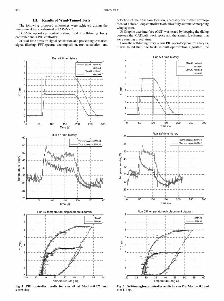
Fig. 4 PID controller results for run 47 at Mach� 0:227 and
�� 0 deg.
0 50 100 150 200 250 300-1
0
1
2
3
4
5
6
7
8
9
Time (s)
Y (
mm
)
Run 55f time history
SMA#1 realised
desiredSMA#2 realised
desired
0 50 100 150 200 250 30020
25
30
35
40
45
50
55
60
Time (s)
Tem
pera
ture
(de
g C
)
Run 55f time history
Thermocouple SMA#1
Thermocouple SMA#2
20 25 30 35 40 45 50 55 600
1
2
3
4
5
6
7
8
Temperature (deg C)
Y (
mm
)
Run 55f temperature-displacement diagram
SMA#1
SMA#2
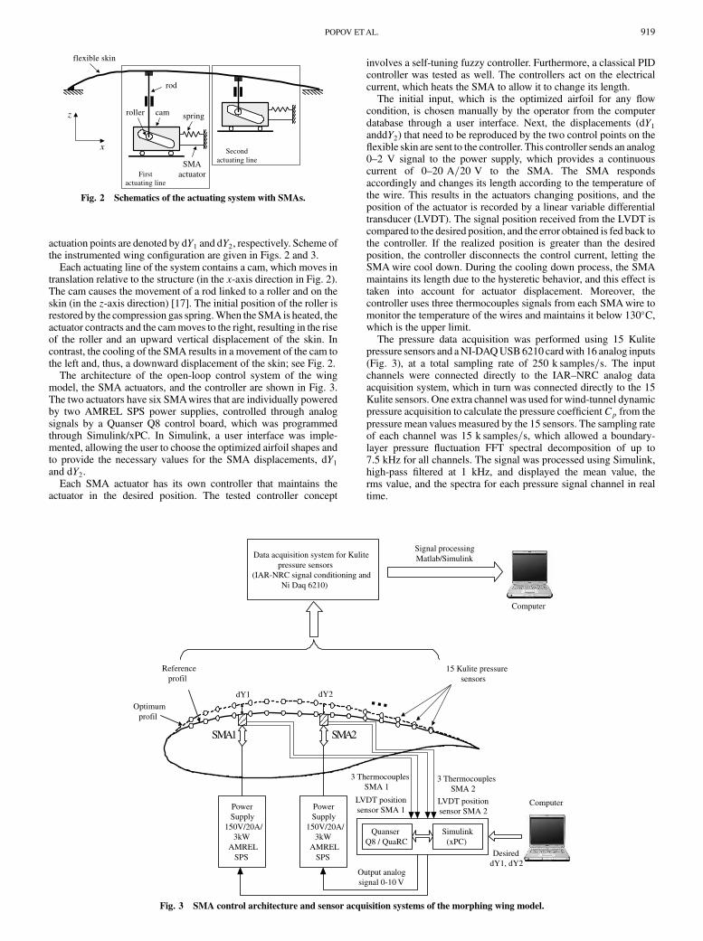
Fig. 5 Self-tuning fuzzy controller results for run 55 atMach� 0:3 and�� 1 deg.
920 POPOV ETAL.
self-tuning fuzzy controller had a smoother control than the PIDcontroller for the same displacements. The PID controller used aswitch that connected and disconnected the power sources supplyingthe SMAwith 10 Awhen heating was needed and 0 Awhen coolingwas needed, which had as a consequence the saw teeth behavior inthe temperature–time-history plot, as shown in Fig. 4. The fuzzycontroller kept a narrow control over the temperature variations in theSMAwires due to the fuzzy algorithm that produced the needed valueof current in the interval of 0–10 A, without going to the extremes ofmaximum or minimum current; the smooth control of the SMAheating is shown in Fig. 5b. The third plot of Figs. 4c and 5c showsthe temperature-displacement hysteresis behavior of the SMAwires,which explains the temperatures needed by SMA to achieve thedesired displacements.
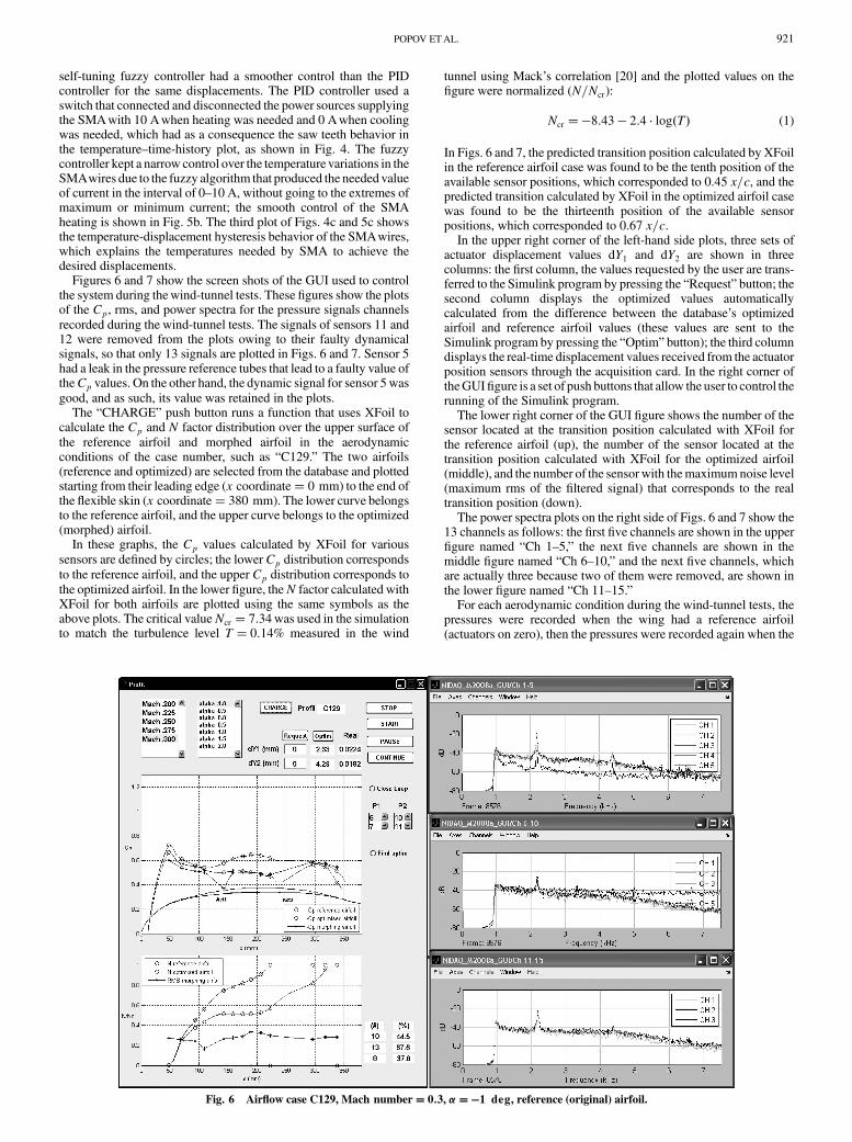
Figures 6 and 7 show the screen shots of the GUI used to controlthe system during thewind-tunnel tests. These figures show the plotsof the Cp, rms, and power spectra for the pressure signals channelsrecorded during the wind-tunnel tests. The signals of sensors 11 and12 were removed from the plots owing to their faulty dynamicalsignals, so that only 13 signals are plotted in Figs. 6 and 7. Sensor 5had a leak in the pressure reference tubes that lead to a faulty value oftheCp values. On the other hand, the dynamic signal for sensor 5wasgood, and as such, its value was retained in the plots.
The “CHARGE” push button runs a function that uses XFoil tocalculate the Cp and N factor distribution over the upper surface ofthe reference airfoil and morphed airfoil in the aerodynamicconditions of the case number, such as “C129.” The two airfoils(reference and optimized) are selected from the database and plottedstarting from their leading edge (x coordinate� 0 mm) to the end ofthe flexible skin (x coordinate� 380 mm). The lower curve belongsto the reference airfoil, and the upper curve belongs to the optimized(morphed) airfoil.
In these graphs, the Cp values calculated by XFoil for varioussensors are defined by circles; the lowerCp distribution correspondsto the reference airfoil, and the upper Cp distribution corresponds tothe optimized airfoil. In the lower figure, theN factor calculated withXFoil for both airfoils are plotted using the same symbols as theabove plots. The critical valueNcr � 7:34was used in the simulationto match the turbulence level T � 0:14% measured in the wind
tunnel using Mack’s correlation [20] and the plotted values on thefigure were normalized (N=Ncr):
Ncr ��8:43 � 2:4 log�T� (1)
In Figs. 6 and 7, the predicted transition position calculated by XFoilin the reference airfoil case was found to be the tenth position of theavailable sensor positions, which corresponded to 0.45 x=c, and thepredicted transition calculated by XFoil in the optimized airfoil casewas found to be the thirteenth position of the available sensorpositions, which corresponded to 0.67 x=c.
In the upper right corner of the left-hand side plots, three sets ofactuator displacement values dY1 and dY2 are shown in threecolumns: the first column, the values requested by the user are trans-ferred to the Simulink program by pressing the “Request” button; thesecond column displays the optimized values automaticallycalculated from the difference between the database’s optimizedairfoil and reference airfoil values (these values are sent to theSimulink program by pressing the “Optim” button); the third columndisplays the real-time displacement values received from the actuatorposition sensors through the acquisition card. In the right corner oftheGUIfigure is a set of push buttons that allow the user to control therunning of the Simulink program.
The lower right corner of the GUI figure shows the number of thesensor located at the transition position calculated with XFoil forthe reference airfoil (up), the number of the sensor located at thetransition position calculated with XFoil for the optimized airfoil(middle), and the number of the sensor with themaximumnoise level(maximum rms of the filtered signal) that corresponds to the realtransition position (down).
The power spectra plots on the right side of Figs. 6 and 7 show the13 channels as follows: the first five channels are shown in the upperfigure named “Ch 1–5,” the next five channels are shown in themiddle figure named “Ch 6–10,” and the next five channels, whichare actually three because two of them were removed, are shown inthe lower figure named “Ch 11–15.”
For each aerodynamic condition during the wind-tunnel tests, thepressures were recorded when the wing had a reference airfoil(actuators on zero), then the pressures were recorded again when the
Fig. 6 Airflow case C129, Mach number� 0:3, ���1 deg, reference (original) airfoil.
POPOV ETAL. 921

wing was morphed to the optimized airfoil (actuators deployed).Figure 6 shows the pressures recorded during the reference phase,and Fig. 7 shows the pressures recorded during morphed phase.
In the reference airfoil case (Fig. 6), the mean values of therecorded pressure signal from the Kulite sensors were displayed inthe same plot with the values calculated by XFoil in real time,showing a goodmatch. The rms plot, displayed in theGUIfigurewithstar symbols, showed the quantity of the noise for each pressuresignal in real time, andwas normalized and displayed in the same plotwith the normalized N factor plot. The sensor with the maximumrms, the eighth sensor plotted, which was located at 0.38 x=c,
indicated the Tollmien–Schlihting wave’s occurrence, which is thetransition indication [18,19]. The spectral decomposition of thepressure signals confirmed the Tollmien–Schlichting wave’s occur-rence in the eighth sensor, visible in the highest power spectra (thethird channel in the middle right-hand side plots) in the frequencyband of 3–7.5 kHz.
In the morphed-to-optimized airfoil case (Fig. 7), the rms plot,displayed in theGUI figurewith star symbols, showed that the sensorwith the maximum rms became the thirteenth sensor plotted, whichwas located at 0.67 x=c. The spectral decomposition of the pressuresignals confirmed theTollmien–Schlichtingwave’s occurrence in the
Fig. 7 Airflow case C129,M � 0:3, ���1 deg, optimized (morphed) airfoil.
Fig. 8 Infrared images atM � 0:3 and ���1 deg: a) reference airfoil, and b) optimized airfoil C129.
922 POPOV ETAL.

thirteenth sensor, visible in the highest power spectra (the thirdchannel in the lower right-hand side plots) in the frequency band of3–7.5 kHz.
In support of the discrete pressure instrumentation, infraredthermography (IR) visualization was performed to detect thetransition location on the upper surface of the morphing wing and tovalidate the pressure sensor analysis. The transition detectionmethodusing IR is based on the differences in the laminar and turbulentconvective heat transfer coefficient and was exacerbated by theartificial increase of model-airflow temperature differences. In theresulting images, the sharp temperature gradient separating high-temperature (white intensity in image) and low-temperature (darkintensity) regions indicates the transition location.
Figure 8 displays the region of themorphingwingmeasured by theIR camera between 0< x=c < 0:7 and 0:7< y=c < 1:4. Flow is fromleft to right. The aft rigid portion of thewing,made of aluminum,wasnot considered in the IR measurements. The two rows of pressuresensors positioned in a V shape and the locations of the SMAactuators as two vertical stripes were visible in the IR images. Theupper row of sensors is the Kulite sensors’ thermal signature and thelower row of sensors is the optical sensors’ thermal signature on theIR image.
Figures 8a and 8b show the IR transition images obtained forM � 0:3 and ���1 deg in the reference and optimized config-urations, respectively. The transition, originally located at approxi-mately x=c� 0:40 in the Kulite sensors’ row and shown with anarrow in Fig. 8a, has beenmoved to x=c� 0:66, shownwith an arrowin Fig. 8b for the morphed wing configuration (case C129). Theoptimization has significantly extended the laminarity of the flowover the upperwing surface, as determined by theKulite sensors. Theairfoil shape optimization has also improved the apparent twodimensionality of the flow: the transition appears vertical in theoptimized morphed case (Fig. 8b), except for the turbulent wedgestriggered by the leak of Kulite sensor 5 (at x=c� 0:2 and y=c� 1).These results, which are in agreement with the Kulite sensors’recorded data, confirm the use of discrete transducers as controlparameters for wing shape optimization.
IV. Conclusions
The paper presented wind-tunnel experimental testing of amorphing wing in an open-loop architecture. The method used foracquiring the pressure data from the external surface of the flexibleskin wing by means of Kulite pressure sensors and the instrumen-tation of the morphing controller were shown. The realized testsshowed that the SMAactuators performedwell, with temperatures oflower than 60�Cundermaximal deployment without interferingwiththe electric systems of the Kulite sensors. Moreover, thewind-tunneltests validated the PID and self-tuning controller architecture foropen-loop operation, and allowed the real-time visualization of thetransition by means of the spectral decomposition and rmscalculation of the pressure signal received fromKulite sensors,whichwere able to detect the unsteady pressure variations during wingtesting with the reference and morphed airfoil in the wind tunnel.
Acknowledgments
The authors would like to thank the Consortium for Research andInnovation in Aerospace in Quebec (CRIAQ) for funding the presentwork, and Thales Avionics and Bombardier Aerospace for theirfinancial and technical contributions. The authors would also like tothank George Henri Simon for initiating the CRIAQ 7.1 project,Philippe Molaret from Thales Avionics, and Eric Laurendeau fromBombardier Aerospace for their collaboration in this work.
References
[1] Zingg, D. W., Diosady, L., and Billing, L., “Adaptive Airfoils for DragReduction at Transonic Speeds,” AIAA Paper 2006-3656, 2006.
[2] Rodriguez, A. R., “Morphing Aircraft Technology Survey,” AIAAPaper 2007-1258, 2007.
[3] Livne, E., “Future of Airplane Aeroelasticity,” Journal of Aircraft,Vol. 40, No. 6, 2003, pp. 1066–1092.doi:10.2514/2.7218
[4] Moorhouse, D., Sanders, B., von Spakovsky, M., and Butt, J.,“Benefits and Design Challenges of Adaptive Structures for MorphingAircraft,” The Aeronautical Journal, 2006, Vol. 110, No. 1105,pp. 157–162.
[5] Alasty, A., Alemohammad, S. H., Khiabani, R. H., and Khalighi, Y.,“Maneuverability Improvement for an Ultra Light Airplane ModelUsing Variable Shape Wing,” AIAA Paper 2004-4831, 2004.
[6] Song, G., and Ma, N., “Robust Control of a Shape Memory AlloyWireActuated Flap,” Smart Materials and Structures, Vol. 16, 2007,pp. N51–N57.doi:10.1088/0964-1726/16/6/N02
[7] Seow,A.K., Liu, Y., andYeo,W.K., “ShapeMemoryAlloy asActuatorto Deflect a Wing Flap,” AIAA Paper 2008-1704, April 2008.
[8] Mason, H. W., Robertshaw, H., and Inman, D. J., “Recent Experimentsin Aerospace and Design Engineering Education,” AIAA Paper 2004-0415, Jan. 2004.
[9] Barbarino, S., Pecora, R., Lecce, L., Concilio, A., Ameduri, S., andCalvi, E., “A Novel SMA-Based Concept for Airfoil StructuralMorphing,” Journal of Materials Engineering and Performance,Vol. 18, No. 5, 2009, pp. 696–705.doi:10.1007/s11665-009-9356-3
[10] Mirone, G., “Design and Demonstrators Testing of Adaptive Airfoilsand Hingeless Wings Actuated by Shape Memory AlloyWires,” SmartStructures and Systems, Vol. 3, No. 1, 2007, pp. 89–114.
[11] Popov. A-V., Labib, M., Fays, J., and Botez, R. M., “Closed LoopControl Simulations on a Morphing Laminar Airfoil Using ShapeMemory Alloys Actuators,” Journal of Aircraft, Vol. 45, No. 5, 2008,pp. 1794–1803.doi:10.2514/1.37073
[12] Coutu, D., Brailovski, V., and Terriault, P., “Promising Benefits of anActive-Extrados Morphing Laminar Wing,” Journal of Aircraft,Vol. 46, No. 2, 2009, pp. 730–731.doi:10.2514/1.40657
[13] Khalid, M., “Navier–Stokes Investigation of Blunt Trailing EdgeAirfoils Using O-Grids,” Journal of Aircraft, Vol. 30, No. 5, 1993,pp. 797–800.doi:10.2514/3.46416
[14] Sainmont, C., Paraschivoiu, I., and Coutu, D., “MultidisciplinaryApproach for the Optimization of a Laminar Airfoil Equipped with aMorphing Upper Surface,” NATO AVT-168 Symposium on MorphingVehicles, 2009.
[15] Drela,M., “Implicit Implementation of theFull en TransitionCriterion,”AIAA Paper 2003-4066, 2003.
[16] Drela, M., and Giles, M. B., “Viscous-Inviscid Analysis of Transonicand Low Reynolds Number Airfoils,” Journal of Aircraft, Vol. 25,No. 10, 1987, pp. 1347–1355.doi:10.2514/3.9789
[17] Georges, T., Brailovski, V., Morellon, E., Coutu, D., and Terriault, P.,“Design of Shape Memory Alloy Actuators for Morphing LaminarWingwith Flexible Extrados,” Journal ofMechanical Design, Vol. 131,No. 9, 2009, pp. 091006-1–091006-9.doi:10.1115/1.3160310
[18] Nitcshe, W., Mirow, P., and Dorfler, T., “Investigations on FlowInstabilities on Airfoils by Means of Piezofoil-Arrays,” Laminar-Turbulent Transition IUTAM Symposium, Springer–Verlag, BerlinHeidelberg, Sept. 1990, pp. 129–135.
[19] Mangalam, S. M., “Real-Time Extraction of Hydrodynamic FlowCharacteristics Using Surface Signature,” IEEE Journal of OceanicEngineering, Vol. 29, No. 3, 2004, pp. 622–630.doi:10.1109/JOE.2004.833098
[20] Mack, L. M., Transition and Laminar Instability, Jet Propulsion Lab,,Publication 77-15, Pasadena, CA, 1977.
POPOV ETAL. 923