Embed Size (px)
Citation preview
International Journal of Computer Applications (0975 – 8887)
Volume 6– No.12, September 2010
29
Modeling, Design & Simulation of an Adaptive Neuro-
Fuzzy Inference System (ANFIS) for Speed Control of
Induction Motor
Ashok Kusagur
Research Scholar, EEE Dept., JNTU, Hyderabad-85, Andhra
Pradesh, India,
Professor & Head of the Department, HMSIT, Tumkur-4,
Karnataka, India.
Dr. S. F. Kodad Director,
Krishnamurthy Inst. of Tech. & Engg., Hyderabad, Andhra Pradesh,
India.
Dr. B V. Sankar Ram Professor, Dept. of EEE,
JNTUCE, Kukatpally, Hydarabad-85, Andhra Pradesh, India.
ABSTRACT
A novel design of an adaptive neuro fuzzy inference strategy
(ANFIS) for controlling some of the parameters, such as speed,
torque, flux, voltage, current, etc. of the induction motor is
presented in this paper. Induction motors are characterized by
highly non-linear, complex and time-varying dynamics and
inaccessibility of some of the states and outputs for
measurements. Hence it can be considered as a challenging
engineering problem in the industrial sector. Various advanced
control techniques has been devised by various researchers across
the world. Some of them are based on the fuzzy techniques.
Fuzzy logic based controllers are considered as potential
candidates for such an application. Fuzzy based controllers
develop a control signal which yields on the firing of the rule
base, which is written on the previous experiences & these rules
are fired which is random in nature. As a result of which, the
outcome of the controller is also random & optimal results may
not be obtained. Selection of the proper rule base depending
upon the situation can be achieved by the use of an ANFIS
controller, which becomes an integrated method of approach for
the control purposes & yields excellent results, which is the
highlight of this paper. In the designed ANFIS scheme, neural
network techniques are used to select a proper rule base, which is
achieved using the back propagation algorithm. This integrated
approach improves the system performance, cost-effectiveness,
efficiency, dynamism, reliability of the designed controller. The
simulation results presented in this paper show the effectiveness
of the method developed & has got faster response time or settling
times. Further, the method developed has got a wide number of
advantages in the industrial sector & can be converted into a real
time application using some interfacing cards.
General Terms Controller design, Damping, Oscillations.
Keywords ANFIS, Fuzzy Logic, Membership functions, ANN, Controller,
Simulink, Matlab, Induction motor, Closed loop, Parameter.
1. INTRODUCTION Intelligent, self-learning or self-organizing controls using expert
systems, artificial intelligence, fuzzy logic, neural networks,
hybrid networks, etc have been recently recognized as the
important tools to improve the performance of the power
electronics based drive systems in the industrial sectors.
Combination of this intelligent control with the adaptiveness
appears today as the most promising research area in the practical
implementation & control of electrical drives. The design and
implementation of industrial control systems often relies on
quantitative mathematical models of the plants (say, induction
motors, generators, DC motors, etc), the controllers, etc. At times,
however, we encounter problems for which controller design
becomes very difficult and expensive to obtain. In such cases, it is
often necessary to observe human experts or experienced
operators of the plants or processes and discover rules governing
their actions for automatic control [33]. In this context, the fuzzy
logic concepts coupled with artificial neural networks play a very
important role in developing the controllers for the plant.
Induction motors play a vital role in the industrial sector
especially in the field of electric drives & control. Without proper
controlling of the speed, it is virtually impossible to achieve the
desired task for a specific application. AC motors, particularly the
squirrel-cage induction motors (SCIM), enjoy several inherent
advantages like simplicity, reliability, low cost and virtually
maintenance-free electrical drives. However, for high dynamic
performance industrial applications, their control remains a
challenging problem because they exhibit significant non-
linearities and many of the parameters, mainly the rotor resistance,
vary with the operating conditions [42]. Field orientation control
(FOC) or vector control [53] of an induction machine achieves
decoupled torque and flux dynamics leading to independent
control of the torque and flux as for a separately excited DC
motor. FOC methods are attractive, but suffer from one major
disadvantage, viz., they are sensitive to motor parametric
variations such as the rotor time constant and an incorrect flux
measurement or estimation at low speeds [52].
Consequently, performance deteriorates and a conventional
controller such as a PID is unable to maintain satisfactory
performance under these conditions. Recently, there has been
observed an increasing interest in combining artificial intelligent
control tools with classical control techniques [42]. The principal
motivations for such a hybrid implementation is that with fuzzy
logic, neural networks & rough sets issues, such as uncertainty or
unknown variations in plant parameters and structure can be dealt
with more effectively, hence improving the robustness of the
control system. Conventional controls have on their side well-
established theoretical backgrounds on stability and allow
International Journal of Computer Applications (0975 – 8887)
Volume 6– No.12, September 2010
30
different design objectives such as steady state and transient
characteristics of the closed loop system to be specified. Several
works were contributed to the design of such hybrid control
schemes which was shown by various researchers in [12], [48].
Classical control systems like PI, PID control have been used,
together with vector control methods, for the speed control of
induction machines by various researchers [6]. The main
drawbacks of the linear control approaches were the sensitivity in
performance to the system parameters variations and inadequate
rejection of external perturbations and load changes [8].
Induction motors are widely used in various industries as prime
work-horses to produce rotational motions and forces. Generally,
variable-speed drives for induction motors require both wide
operating range of speed and fast torque response, regardless of
load variations. Usually, the classical control is used in majority
of the electrical motor drives. Conventional control makes use of
the mathematical model for the controlling of the system. When
there are system parametric variations or environmental
disturbance (say noise), behavior of system is not satisfactory &
deviates from the desired performance [11].
In addition, usual computation of system mathematical model is
difficult or impossible. To obtain the exact mathematic model of
the system, then one has to do some identification techniques such
as the system identification & obtain the plant model. Moreover,
the design and tuning of conventional controller increases the
implementation cost and adds additional complexity in the control
system & thus, may reduce the reliability of the control system.
Hence, the fuzzy based techniques are used to overcome this kind
of problems. Efficient torque control of induction motor drives in
combination with resonant DC-link input filters can lead to a type
of stability problem that is known as negative impedance
instability. To overcome this, Henrik et.al., proposed a solution
to the above problem by using the concept of non-linear system
stabilizing controller in [29] with the plant.
Recent years have witnessed rapidly growing popularity of fuzzy
control systems in engineering applications. The numerous
successful applications of fuzzy control have sparked a flurry of
activities in the analysis and design of fuzzy control systems [34].
Fuzzy logic based flexible multi-bus voltage control of power
systems was developed by Ashok et.al. in [32]. In the last few
years, fuzzy logic has met a growing interest in many motor
control applications due to its non-linearities handling features
and independence of the plant modeling. The fuzzy controller
(FLC) operates in a knowledge-based way, and its knowledge
relies on a set of linguistic if-then rules, like a human operator.
Ashok et.al. [5] developed a novel design of a Takagi-Sugeno
fuzzy strategy for induction motor speed control, which yielded
excellent results, especially in the settling times of the various
responses. Ramon et.al. [46] presented a rule-based fuzzy logic
controller applied to a scalar closed loop induction motor control
with slip regulation & they also compared their results with those
of a PI controller. They used a new linguistic rule table in FLC to
adjust the motor control speed. A fuzzy controller of the type of
the Takagi-Sugeno model was investigated in [15] by Chen &
Wong. AI based design of a fuzzy logic scheme for speed control
of induction motors using SVPWM technique was proposed by
the authors Ashok et.al. in [3].
There are a number of significant control methods available for
induction motors including scalar control, vector or field-oriented
control, direct torque and flux control, sliding mode control, and
the adaptive control [11]. Scalar control is aimed at controlling
the induction machine to operate at the steady state, by varying
the amplitude and frequency of the fundamental supply voltage
[13]. A method to use of an improved V/f control for high voltage
induction motors & its stability was proposed in [9]. The scalar
controlled drive, in contrast to vector or field-oriented controlled
one, is easy to implement, but provides somewhat inferior
performance. This control method provides limited speed
accuracy especially in the low speed range and poor dynamic
torque response.
T-S fuzzy model-based impulsive control of chaotic systems with
exponential decay rate was discussed by X. Liu, and S. Zhong in
[37]. In their paper, they presented a new approach for stability
analysis of the fuzzy impulsive controllers in which the fuzzy
system was presented by Takagi-Sugeno model. Further, Ashok
et.al. [5] used the TS model to develop a hybrid control scheme to
control the speed of the IM, which yielded excellent results.
Zhang & Jiang proposed an efficient approach for indirect field-
oriented control of induction machines based on the synergetic
control method, taking speed control of an induction motor by
using an example in [56].
Space Vector Pulse Width Modulation (SVPWM) method is one
of the advanced, computation-intensive PWM method and
possibly the best among all the PWM techniques for variable
frequency drive applications. Because of its superior performance
characteristics, it has been finding widespread applications in
recent years. Satean, et.al., presented a novel control technique of
control of the induction motors using space vector pulse width
modulation method in [47]. They even developed an excellent 3-
φ bridge inverter which was used to apply a balanced 3φ
voltages to the SCIM. In due course, fuzzy logic concept was
introduced by Lotfi Zadeh in 1965. Many researchers used this
FLC concept developed by Zadeh to develop controllers for their
applications, which had yielded good results. Thus, this FLC
concept remained as a popular control scheme in the control
world even today. Arulmozhiyal & Baskaran [45] described in
brief a number of fuzzy control logic applications on various
plants in their paper. They even devised a new control strategy to
control the speed of IMs using FLC technique.
Fuzzy Logic control (FLC) has proven effective for complex, non-
linear and imprecisely defined processes for which standard
model based control techniques are impractical or impossible
[19]. Fuzzy Logic, deals with problems that have vagueness,
uncertainty and use membership functions with values varying
between 0 and 1 [18]. This means that if the reliable data is not
available or if the controlled system is too complex to derive the
required decision rules, development of a fuzzy logic controller
become quite difficult. In this case, the expert knowledge can be
made use of for framing the proper rules which can be further
used to tune the controller for obtaining better results [57].
Furthermore, an optimal fuzzy logic controller cannot be achieved
by trial-and-error. These drawbacks have limited the application
of fuzzy logic control [28].
Some efforts have been made to solve these problems and
simplify the task of tuning parameters and developing rules for the
controller [40]. These approaches mainly use adaptation or
learning techniques drawn from artificial intelligence or neural
network theories. Application of fuzzy logic control for the
International Journal of Computer Applications (0975 – 8887)
Volume 6– No.12, September 2010
31
control a speed induction motor using space vector pulse width
modulation is not quite new [44]. However, there is no systematic
method for designing and tuning the fuzzy logic controller & one
has to design using some trail & error using the IF, ELSE, THEN
rules. Neuro fuzzy robust controllers for AC drive systems using
predictive controller was developed by Yashuhiko et.al. [55]
which reduced the plant & the observation noise.
Consoli et.al. presented an adaptive vector based control of IM
drives based on neuro fuzzy approach in their paper in [20]. They
performed an experimental realization of an MRAC speed
controller for the indirect field oriented IM drives based on fuzzy
laws for the adaptive process & a neuro-fuzzy procedure to
optimize the fuzzy rules. A model reference adaptive flux
observer based adaptive neuro-fuzzy control (ANFIS) of IM
drives was presented by Nasir Uddin & Hao Wen in [43]. The
observer model was developed based on a reference flux model &
a closed loop gopinath flux observer, which combines current &
voltage model flux observes. They investigated the performance
of the designed drive at different dynamic operating conditions.
A simple DTC neuro-fuzzy control of PWM inverter fed IM drive
was proposed by Grabowski, Marian & Bose in [25]. They
applied an adaptive neuro fuzzy inference system to achieve high-
performance decoupled flux & torque control using an
experimental approach coupled with DSP TMS320C31 card.
Aware et.al. [7] proposed a new type of adaptive neuro-fuzzy
controller (ANFIS) for voltage source inverted fed IMs. In this
paper, they replaced the conventional PI / PID controller by the
fuzzy controller in speed controller loop & implemented using
DSP interfacing card. ANFIS which tunes the fuzzy inference
system with a back propagation algorithm based on a collection of
input-output data is implemented here.
Mihoub et.al. [39] proposed a ANFIS controller to obtain a high
dynamic performance in AC machines. In their work, they used
fuzzy controller first & then the neuro-fuzzy controller. Finally,
they proved that the latter one is better than the former one in
terms of the dynamism. An excellent sensorless speed control of
IM drives using a robust & adaptive neuro fuzzy based intelligent
controller was formulated by Farzan Rashidi [23]. An ANN was
adopted to estimate the motor speed & to provide a sensorless
speed estimator system by evaluating for a wide range of
operating conditions such as start ups, step changes in the
reference speeds, unknown load torque with parameter variations.
An IM spindle motor drive using synchronous PWM & dead time
compensatory techniques with an ANFIS controller was proposed
by Faa & Rong for advanced spindle motor applications by
performing an real time experiment [22]. Since the control
characteristics & motor parameters for the high speed IM drive
were time varying, they proposed an ANFIS scheme to control the
rotor speed. The plant here was identified by a fuzzy NN
identifier to provide the sensitivity info of the drive system to the
adaptive controller using a back propagation algo to train the
network online. Mokhtar & Sofiane [41] developed an adaptive
speed control of an hybrid fuzzy-neural network for a high
performance IM drive to improve the performance & robustness
of the IM drive under non-linear loads & parametric variations.
Many researchers had worked on the fuzzy logic based on-line
efficiency control for an indirect vector controlled IM drive.
Bimal Bose et.al. [10] extended the same control technique to a
stator flux oriented electric vehicle IM drive & then implemented
the fuzzy controller by a dynamic back propagation algorithm
using an ANFIS controller. They further verified the simulated
results using an DSP based hardware. Haider et.al. [27]
presented the design and implementation of Fuzzy-SMC-PI
methodology to control the flux and speed of an induction motor.
The Fuzzy-SMC-PI was basically a combination of Sliding Mode
Control (SMC) and PI control methodologies through fuzzy logic,
but the drawback being the chattering during the time of
switching.
In [16] & [36], the researchers implemented a fuzzy logic
controller to adjust the boundary layer width according to the
speed error. The drawback of their controller is that it depends on
the equivalent control & on the system parameters. Two
researchers, Takagi & Sugeno developed a excellent control
scheme for control of various applications in the industrial sector.
This controller had many advantages over the other methods
discussed so far. Many researchers started using their models for
their applications. Zie, Ling & Jhang [54] presented a TS model
identification method by which a great number of systems whose
parameters vary dramatically with working states can be identified
via Fuzzy Neural Networks (FNN). The suggested method could
overcome the drawbacks of traditional linear system identification
methods which are only effective under certain narrow working
states and provide global dynamic description based on which
further control of such systems may be carried out.
In the above mentioned papers, there were a lot of drawbacks &
disadvantages, one of the parameter being the settling time of the
responses & the proper selection of the rule base. The responses
had taken a lot of time to reach the final steady state value. In this
paper, a sincere attempt is made to reduce the settling time of the
responses & make the speed of response very fast by designing an
efficient controller using ANFIS control strategy. The proper rule
base is selected using an intelligently developed back propagation
algo. Here, we have formulated this complex control strategy for
the speed control of IM, which has yielded excellent results
compared to the others mentioned in the literature survey above.
The results of our work have showed a very low transient
response and a non-oscillating steady state response with
excellent stabilization.
The structure of the research work (flow / organization of the
paper) presented in this paper is organized in the following
sequence. A brief review of the literature survey of the related
work was presented in the previous paragraphs in the introductory
section. Section 2 presents the mathematical modelling of the
induction motor. Review about the adaptive neuro fuzzy
inference scheme used in the design of the controller is presented
in section 3. The design of the ANFIS controller is presented in
section 4. The section 5 shows the development of the simulink
model for the speed control of the induction motor. The
simulation results & the discussion on it are presented in the
section 6. This is followed by the conclusions in the concluding
section, the nomenclatures, abbreviations, references & the author
biographies.
2. MODELLING OF INDUCTION MOTOR
In the control of any power electronics drive system (say a motor);
to start with, a mathematical model of the plant is required. This
mathematical model is required further to design any type of
controller to control the process of the plant. The mathematical
model can be obtained by various methods, viz., from first
International Journal of Computer Applications (0975 – 8887)
Volume 6– No.12, September 2010
32
principles, system identification methods, etc. This mathematical
model may be a linear / non-linear differential equation or a
transfer function (in s or z-domain) or in state space form. In this
section, we present the mathematical model of the induction
motor. The mathematical model of the SCIM system used in our
work consists of space vector PWM voltage source inverter,
induction motor, direct flux and the torque control [56].
The drawback of the coupling effect in the control of SCIMs is
that, it gives sluggish response and the system is easily prone to
instability because of a high-order system effect. This problem can
be solved by making use of either vector control or field-oriented
control. When this type of control strategy is adopted, it can
make an induction motor to be controlled like a separately excited
DC motor. Of course, the control of AC drives can exhibit better
performance. Thus, due to the above mentioned reasons, an
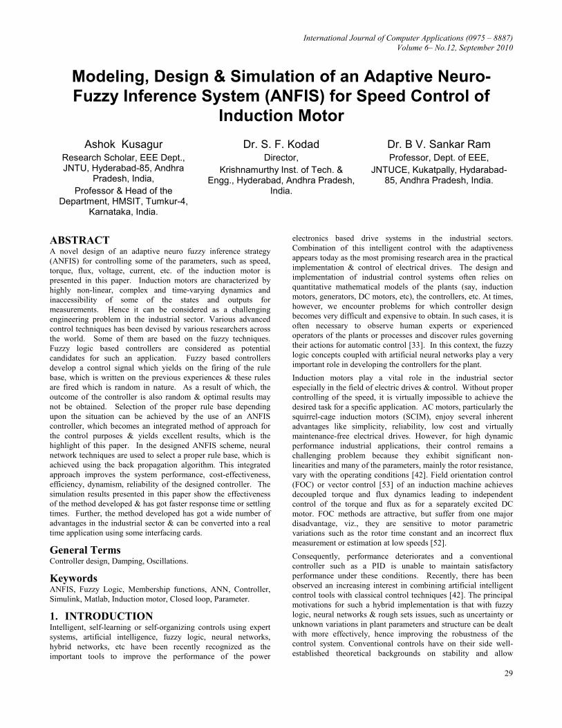
induction motor model was established using a rotating (d, q)
field reference (without saturation) concept [56]. The power
circuit of the 3-φ induction motor is shown in the Fig. 1.
Fig. 1 : Power circuit connection diagram for the IM
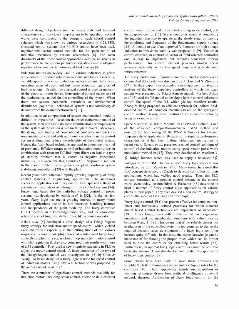
The equivalent circuit used for obtaining the mathematical model
of the induction motor is shown in the Fig. 2.
Rsω λd sq Lls Llr
ω λdA rq Rr
LmVsd Vrd
λsdddt
λrdddt
(a) d-axis
Rsω λd sd Lls Llr
ω λdA rd Rr
LmVsq Vrq
λsqddt
λrqddt
(b) q-axis
Fig. 2 : Equivalent circuit of induction motor in d - q frame
An induction motor model is then used to predict the voltage
required to drive the flux, torque & the speed to the demanded
values. This calculated voltage is then synthesized using the
space vector modulation. The stator & rotor voltage equations are
given by [56]
sd s sd sd d sq
dV R i
dtλ ω λ= + − , (1)
sddsqsqssq λωλdt
diRV ++= , (2)
rqdArdrdrrd λωλdt
diRV −+= (3)
rddArqrqrrq λωλdt
diRV ++= , (4)
where Vsd and Vsq, Vrd and Vrq are the direct axes & quadrature
axes stator and rotor voltages [56].
The squirrel-cage induction motor considered for the simulation
study in this paper, has the d and q-axis components of the rotor
voltage zero. The flux linkages to the currents are related by the
Eq. (5) as
0 0
0 0;
0 0
0 0
sd sd s m
sq sq s m
rd rd m r
rq rq m r
i L L
i L LM M
i L L
i L L
λλλλ
= =
. (5)
The electrical part of an induction motor can thus be described by
a fourth-order state space model which is given in Eq. (6), by
combining equations (1) - (5) as [56]
( ) ( )( ) ( )
+−−−−
−+−
−+−
−−+
=
qr
qr
ds
qs
rrrremmre
rrerrmrem
mmessse
mbmsess
qr
qr
ds
qs
i
i
i
i
sLRLωωsLLωω
LωωsLRLωωsL
pLLωsLRLω
LωsLLωsLR
v
v
v
v
, (6)
where s is the laplacian operator. By superposition, i.e., adding
the torques acting on the d-axis and the q-axis of the rotor
windings, the instantaneous torque produced in the
electromechanical interaction is given by
( )rqrdrdrqem iλiλP
T −
=22
3. (8)
The electromagnetic torque expressed in terms of inductances is
given by
( )rqsdrdsqmem iiiiLP
T −
=22
3. (9)
The mechanical part of the motor is modeled by the equation [56].
( )
eq
Lrqsdrdsqm
eq
LemMech
J
TiiiiLP
J
TT
dt
d−−
=−
=ω22
3
, (10)
where,
=eqJ Equivalent Moment of Inertia,
,msslipdA ωωωω −==
mrlrmsls LLLLLL +=+= , .
This IMs mathematical model is further used to design a adaptive
controller using ANFIS control strategy in the next but next
section. The induction motor can be observed as a system of
electric and magnetic circuits, which are coupled magnetically and
electrically. A 3-Phase balanced sinusoidal voltages given by
[56].
International Journal of Computer Applications (0975 – 8887)
Volume 6– No.12, September 2010
33
tVV mAn ωcos= , (11)
−=3
2cos
πωtVV mBn , (12)
+=3
2cos
πωtVV mCn (13)
are applied to the IM using the equation
[ ]CnBnAn vaavv 2
3
2++=V (14)
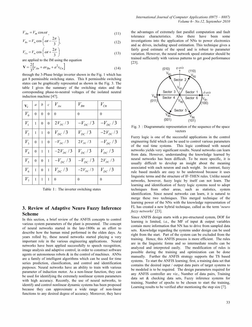
through the 3-Phase bridge inverter shown in the Fig. 1 which has
got 8 permissible switching states. This 8 permissible switching
states can be graphically represented as shown in the Fig. 3. The
table I gives the summary of the switching states and the
corresponding phase-to-neutral voltages of the isolated neutral
induction machine [47].
Vi a b c AnV nBV nCV
0V 0 0 0 0 0 0
1V 1 0 0 2 / 3DCV / 3DCV− / 3DCV−
2V 1 1 0 / 3DCV / 3DCV 2 / 3DCV−
3V 0 1 0 / 3DCV− 2 / 3DCV / 3DCV−
4V 0 1 1 2 / 3DCV− / 3DCV / 3DCV
5V 0 0 1 / 3DCV− / 3DCV− 2 / 3DCV
6V 1 0 1 / 3DCV 2 / 3DCV− / 3DCV
7V 1 1 1 0 0 0
Table I : The inverter switching states
3. Review of Adaptive Neuro Fuzzy Inference
Scheme
In this section, a brief review of the ANFIS concepts to control
various system parameters of the plant is presented. The concept
of neural networks started in the late-1800s as an effort to
describe how the human mind performed in the olden days. As
years rolled by, these neural networks started playing a very
important role in the various engineering applications. Neural
networks have been applied successfully to speech recognition,
image analysis and adaptive control, in order to construct software
agents or autonomous robots & in the control of machines. ANNs
are a family of intelligent algorithms which can be used for time
series prediction, classification, and control and identification
purposes. Neural networks have an ability to train with various
parameter of induction motor. As a non-linear function, they can
be used for identifying the extremely nonlinear system parameters
with high accuracy. Recently, the use of neural networks, to
identify and control nonlinear dynamic systems has been proposed
because they can approximate a wide range of non-linear
functions to any desired degree of accuracy. Moreover, they have
the advantages of extremely fast parallel computation and fault
tolerance characteristics. Also there have been some
investigations into the application of NNs to power electronics
and ac drives, including speed estimation. This technique gives a
fairly good estimate of the speed and is robust to parameter
variation. However, the neural network speed estimator should be
trained sufficiently with various patterns to get good performance
[23].
Sector 1
Sector 2
Sector 3
Sector 4
Sector 5
Sector 6 Vs1
Vs2Vs3
Vs4
Vs5 Vs6
(100)
(110)(010)
(011)
(001) (101)
d-axis
q-axis
Vs7
Vs0
Fig. 3 : Diagrammatic representation of the sequence of the space
vectors
Fuzzy logic is one of the successful applications in the control
engineering field which can be used to control various parameters
of the real time systems. This logic combined with neural
networks yields very significant results. Neural networks can learn
from data. However, understanding the knowledge learned by
neural networks has been difficult. To be more specific, it is
usually difficult to develop an insight about the meaning
associated with each neuron and each weight. In contrast, fuzzy
rule based models are easy to be understood because it uses
linguistic terms and the structure of IF-THEN rules. Unlike neural
networks, however, fuzzy logic by itself can not learn. The
learning and identification of fuzzy logic systems need to adopt
techniques from other areas, such as statistics, system
identification. Since neural networks can learn, it is natural to
merge these two techniques. This merged technique of the
learning power of the NNs with the knowledge representation of
FL has created a new hybrid technique, called as the term ‘neuro
fuzzy networks’ [23].
Since ANFIS design starts with a pre-structured system, DOF for
learning is limited, i.e., the MF of input & output variables
contain more information that NN has to drive from sampled data
sets. Knowledge regarding the systems under design can be used
right from the start. Part of the system can be excluded from the
training. Hence, this ANFIS process is more efficient. The rules
are in the linguistic forms and so intermediate results can be
analyzed and interpreted easily. The modification of rules is
possible during the training and optimization can be done
manually. Further the ANFIS strategy supports the TS based
systems. To start the ANFIS learning; first, a training data set that
contains the desired input / output data pairs of target systems to
be modeled is to be required. The design parameters required for
any ANFIS controller are viz., Number of data pairs, Training
data set & checking data sets, Fuzzy inference systems for
training, Number of epochs to be chosen to start the training,
Learning results to be verified after mentioning the step size [7].
International Journal of Computer Applications (0975 – 8887)
Volume 6– No.12, September 2010
34
In this context, the general ANFIS control structure for the control
of any plant is presented here as follows [25], [43]. This structure
contains the same components as the FIS, expect for the NN
block. The structure of the network is composed of a set of units
(and connections) arranged into five connected network layers,
viz., l1 to l5 as shown in the Fig. 18.
Layer 1 : This layer consists of input variables (membership
functions), viz., input 1 & input 2. Here, triangular
or bell shaped MF can be used. This layer just
supplies the input values ix to the next layer, where i
= 1 to n.
Layer 2 : This layer (membership layer) checks for the weights
of each MFs. It receives the input values ix from the
1st layer and act as MFs to represent the fuzzy sets of
the respective input variables. Further, it computes
the membership values which specify the degree to
which the input value ix belongs to the fuzzy set,
which acts as the inputs to the next layer.
Layer 3 : This layer is called as the rule layer. Each node (each
neuron) in this layer performs the pre-condition
matching of the fuzzy rules, i.e., they compute the
activation level of each rule, the number of layers
being equal to the number of fuzzy rules. Each node
of these layers calculates the weights which are
normalized.
Layer 4 : This layer is called as the defuzzification layer &
provides the output values y resulting from the
inference of rules. Connections between the layers l3
& l4 are weighted by the fuzzy singletons that
represent another set of parameters for the neuro
fuzzy network.
Layer 5 : This layer is called as the output layer which sums up
all the inputs coming from the layer 4 and transforms
the fuzzy classification results into a crisp (binary).
The ANFIS structure is tuned automatically by least-square-
estimation & the back propagation algorithm. The algorithm
shown above is used in the next section to develop the ANFIS
controller to control the various parameters of the induction
motor. Because of its flexibility, the ANFIS strategy can be used
for a wide range of control applications.
4. Controller design
A controller is a device which controls each & every operation in
the system making decisions. From the control system point of
view, it is bringing stability to the system when there is a
disturbance, thus safeguarding the equipment from further
damages. It may be hardware based controller or a software based
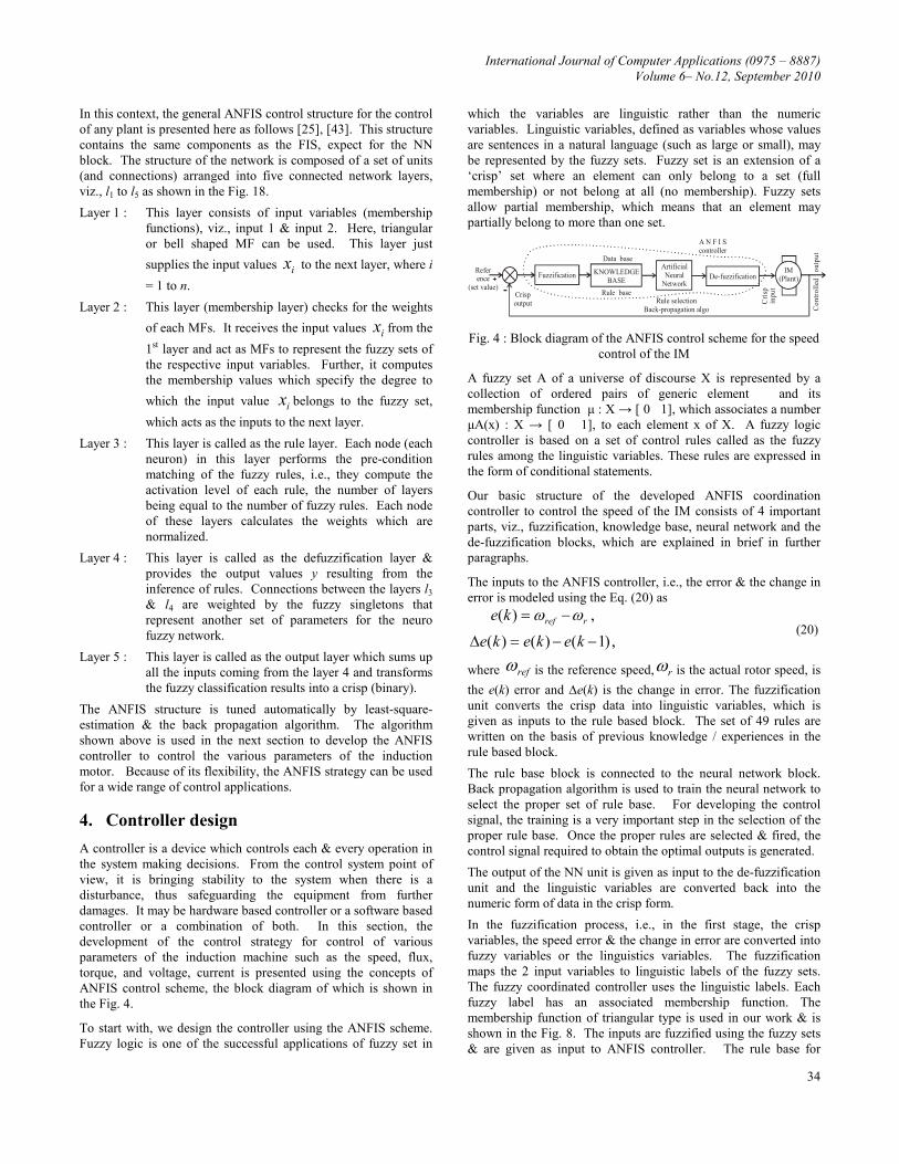
controller or a combination of both. In this section, the
development of the control strategy for control of various
parameters of the induction machine such as the speed, flux,
torque, and voltage, current is presented using the concepts of
ANFIS control scheme, the block diagram of which is shown in
the Fig. 4.
To start with, we design the controller using the ANFIS scheme.
Fuzzy logic is one of the successful applications of fuzzy set in
which the variables are linguistic rather than the numeric
variables. Linguistic variables, defined as variables whose values
are sentences in a natural language (such as large or small), may
be represented by the fuzzy sets. Fuzzy set is an extension of a
‘crisp’ set where an element can only belong to a set (full
membership) or not belong at all (no membership). Fuzzy sets
allow partial membership, which means that an element may
partially belong to more than one set.
Fuzzification De-fuzzification
Controlled
output
Reference
(set value)
IM(Plant)
A N F I Scontroller
Crisp
input
Crispoutput
Rule base
Data base
KNOWLEDGE BASE
ArtificialNeuralNetwork
Rule selectionBack-propagation algo
Fig. 4 : Block diagram of the ANFIS control scheme for the speed
control of the IM
A fuzzy set A of a universe of discourse X is represented by a
collection of ordered pairs of generic element and its
membership function µ : X → [ 0 1], which associates a number
µA(x) : X → [ 0 1], to each element x of X. A fuzzy logic
controller is based on a set of control rules called as the fuzzy
rules among the linguistic variables. These rules are expressed in
the form of conditional statements.
Our basic structure of the developed ANFIS coordination
controller to control the speed of the IM consists of 4 important
parts, viz., fuzzification, knowledge base, neural network and the
de-fuzzification blocks, which are explained in brief in further
paragraphs.
The inputs to the ANFIS controller, i.e., the error & the change in
error is modeled using the Eq. (20) as
,)1()()(
,)(
−−=∆
−=
kekeke
ke rref ωω (20)
where refω is the reference speed, rω is the actual rotor speed, is
the e(k) error and ∆e(k) is the change in error. The fuzzification unit converts the crisp data into linguistic variables, which is
given as inputs to the rule based block. The set of 49 rules are
written on the basis of previous knowledge / experiences in the
rule based block.
The rule base block is connected to the neural network block.
Back propagation algorithm is used to train the neural network to
select the proper set of rule base. For developing the control
signal, the training is a very important step in the selection of the
proper rule base. Once the proper rules are selected & fired, the
control signal required to obtain the optimal outputs is generated.
The output of the NN unit is given as input to the de-fuzzification
unit and the linguistic variables are converted back into the
numeric form of data in the crisp form.
In the fuzzification process, i.e., in the first stage, the crisp
variables, the speed error & the change in error are converted into
fuzzy variables or the linguistics variables. The fuzzification
maps the 2 input variables to linguistic labels of the fuzzy sets.
The fuzzy coordinated controller uses the linguistic labels. Each
fuzzy label has an associated membership function. The
membership function of triangular type is used in our work & is
shown in the Fig. 8. The inputs are fuzzified using the fuzzy sets
& are given as input to ANFIS controller. The rule base for
International Journal of Computer Applications (0975 – 8887)
Volume 6– No.12, September 2010
35
selection of proper rules using the back propagation algorithm is
written as shown in the table II.
E
∆E NB NM NS ZE PS PM PB
NB NB NB NB NB NM NS ZE
NM NB NB NM NM NS ZE PS
NS NB NM NS NS ZE PS PM
ZE NB NM NS ZE PS PM PB
PS NM NS ZE PS PS PM PB
PM NS ZE PS PM PM PB PB
PB ZE PS PM PB PB PB PB
Table II : Rule base for controlling the speed.
The developed fuzzy rules ( ) 4977 =× included in the ANFIS
controller is given below in the form of an algorithm as follows :
1. If (speederror is NB) and (changeinerror is NB) then (output1 is NS) (1)
2. If (speederror is NB) and (changeinerror is NM) then (output1 is NS) (1)
3. If (speederror is NB) and (changeinerror is NS) then (output1 is NS) (1)
4. If (speederror is NB) and (changeinerror is NS) then (output1 is NS) (1)
5. If (speederror is NB) and (changeinerror is PS) then (output1 is NM) (1)
6. If (speederror is NB) and (changeinerror is PM) then (output1 is NS) (1)
7. If (speederror is NB) and (changeinerror is PB) then (output1 is Z) (1)
8. If (speederror is NM) and (changeinerror is NB) then (output1 is NS) (1)
9. If (speederror is NM) and (changeinerror is NM) then (output1 is NS) (1)
10. If (speederror is NM) and (changeinerror is NS) then (output1 is NB) (1)
11. If (speederror is NM) and (changeinerror is Z) then (output1 is NM) (1)
12. If (speederror is NM) and (changeinerror is PS) then (output1 is NS) (1)
13. If (speederror is NM) and (changeinerror is PM) then (output1 is Z) (1)
14. If (speederror is NM) and (changeinerror is PB) then (output1 is PS) (1)
15. If (speederror is NS) and (changeinerror is NB) then (output1 is NS) (1)
16. If (speederror is NS) and (changeinerror is NM) then (output1 is NB) (1)
17. If (speederror is NS) and (changeinerror is NS) then (output1 is NM) (1)
18. If (speederror is NS) and (changeinerror is Z) then (output1 is NS) (1)
19. If (speederror is NS) and (changeinerror is PS) then (output1 is Z) (1)
20. If (speederror is NS) and (changeinerror is PM) then (output1 is PS) (1)
21. If (speederror is NS) and (changeinerror is PB) then (output1 is PM) (1)
22. If (speederror is Z) and (changeinerror is NB) then (output1 is NB) (1)
23. If (speederror is Z) and (changeinerror is NM) then (output1 is NM) (1)
24. If (speederror is Z) and (changeinerror is NS) then (output1 is NS) (1)
25. If (speederror is Z) and (changeinerror is PB) then (output1 is PB) (1)
26. If (speederror is Z) and (changeinerror is Z) then (output1 is Z) (1)
27. If (speederror is Z) and (changeinerror is PS) then (output1 is PS) (1)
28. If (speederror is Z) and (changeinerror is PM) then (output1 is PM) (1)
29. If (speederror is PS) and (changeinerror is NB) then (output1 is NM) (1)
30. If (speederror is PS) and (changeinerror is NM) then (output1 is NS) (1)
31. If (speederror is PS) and (changeinerror is NS) then (output1 is Z) (1)
32. If (speederror is PS) and (changeinerror is Z) then (output1 is PS) (1)
33. If (speederror is PS) and (changeinerror is PS) then (output1 is PM) (1)
34. If (speederror is PS) and (changeinerror is PM) then (output1 is PB) (1)
35. If (speederror is PS) and (changeinerror is PB) then (output1 is PS) (1)
36. If (speederror is PM) and (changeinerror is NB) then (output1 is NS) (1)
37. If (speederror is PM) and (changeinerror is NM) then (output1 is Z) (1)
38. If (speederror is PM) and (changeinerror is NS) then (output1 is PS) (1)
39. If (speederror is PM) and (changeinerror is Z) then (output1 is PM) (1)
40. If (speederror is PM) and (changeinerror is PS) then (output1 is PB) (1)
41. If (speederror is PM) and (changeinerror is PM) then (output1 is PS) (1)
42. If (speederror is PM) and (changeinerror is PB) then (output1 is PB) (1)
43. If (speederror is PB) and (changeinerror is NB) then (output1 is Z) (1)
44. If (speederror is PB) and (changeinerror is NM) then (output1 is PS) (1)
45. If (speederror is PB) and (changeinerror is NS) then (output1 is PM) (1)
46. If (speederror is PB) and (changeinerror is Z) then (output1 is PB) (1)
47. If (speederror is PB) and (changeinerror is PS) then (output1 is PB) (1)
48. If (speederror is PB) and (changeinerror is PM) then (output1 is PB) (1)
49. If (speederror is PB) and (changeinerror is PB) then (output1 is PB) (1)
The control decisions are made based on the fuzzified variables in
the Table II. The inference involves a set of rules for determining
the output decisions. As there are 2 input variables & 7 fuzzified
variables, the controller has a set of 49 rules for the ANFIS
controller. Out of these 49 rules [Fig. 9], the proper rules are
selected by the training of the neural network with the help of
back propagation algorithm & these selected rules are fired.
Further, it has to be converted into numerical output, i.e., they
have to be de-fuzzified. This process is what is called as de-
fuzzification, which is the process of producing a quantifiable
result in fuzzy logic.
The defuzzifcation transforms fuzzy set information into numeric
data information. There are so many methods to perform the
defuzzifcation, viz., centre of gravity method, centre of singleton
method, maximum methods, the marginal properties of the
centroid methods & so on. In our work, we use the centre of
gravity method. The output of the defuzzification unit will
generate the control commands which in turn is given as input
(called as the crisp input) to the plant through the inverter. If
there is any deviation in the controlled output (crisp output), this
is fed back & compared with the set value & the error signal is
generated which is given as input to the ANFIS controller which
in turn brings back the output to the normal value, thus
maintaining stability in the system. Finally, the controlled output
signal, i.e., y is given by Eq. (21) as
∑
∑ ∑
=
= =
+Λ+
= R
i
i
R
i
R
i
qiq
iii xaxa
y
1
1 1
11
µ
µµ
. (21)
This controlled output y is nothing but the final output of the
controller and is the weighted average of the proper rule based
outputs, which are selected by the back propagation algorithm.
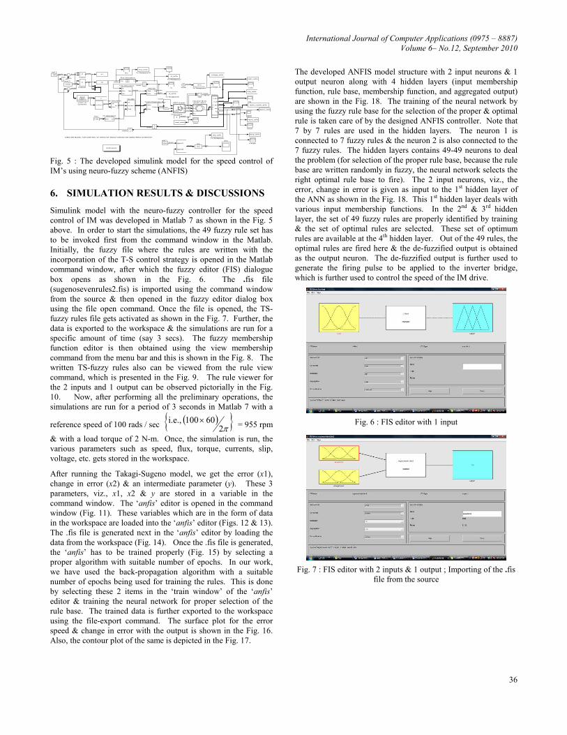
5. DEVELOPMENT OF SIMULINK MODEL
Simulink model for the control of various parameters of the
induction motor was developed in Matlab 7. This simulink model
with the ANFIS controller was developed using the various
toolboxes available in the simulink library such as the power
system, power electronics, control system, signal processing
toolboxes & from its basic functions. The entire system modeled
in Simulink is a closed loop feedback control system consisting of
the plants, controllers, samplers, comparators, feedback systems,
constants, buses, the mux, de-mux, summers, adders, gain blocks,
multipliers, constant blocks, CT & DT blocks, ANFIS editor
blocks, clocks, sub-systems, integrators, state-space models, the
output sinks (scopes), the input sources, work-space blocks, etc.
The developed simulink model for the control of various
parameters of the SCIM is shown in the Fig. 5. The specifications
of the SCIM used for simulation purposes are given in the
appendix.
International Journal of Computer Applications (0975 – 8887)
Volume 6– No.12, September 2010
36
SIMULINK MODEL FOR CONTROL OF SPEED OF INDUCTION MOTOR USING ANFIS STRATEGY
1/100
wref 3
100
wref 2
1800
wref 1
voltage_ab
torque
stator current
speed
f(u)
slip rt angle
Continuous
irdq
ir abc
Te*
PhirIq*
iqs* Calculation
iq
Phir* Id*
id* Calculation
idflux
Vdc
+-
v
Vab
z
1
z
1
z
1
z
1irabc_anfis
iq_anfi s
To Workspace8
id_anfis
To Workspace7
slip_anfis
To Workspace6
time
To Workspace5
torque_anfis
speed_anfis
y
load_anfis
stator_current_anfis
voltage_anfis
flux_anfis
To Workspace12
rtang_anfis
irdq_anfis
x2
x1
Iq
Phir
wm
Teta
Teta Calculation
In1Out1
In1Out1
In1Out1
Sl ip
Product1
Product
0.96
Phir*
signal1
signal2
2
Load_torque
Load
A
B
C
Tm
m
Induction Motor
50 HP / 460 V
+
-
pulses
A
B
C
IGBT Inverter
IdPhirFlux
Calc.
Flux Calculation
m
ir_abc
ir_qd
is_abc
wm
Te
thetam
Demux
Id*
Iq*
Teta
Iabc*
DQ-ABC
Iabc*
Iabc
Pulses
Current Regulator
Clock
Teta
Iabc
Id
Iq
ABC-DQ
A N F I S
Controller double
double
double
double
double
double
double
double
double
double
doubledouble
double
double
double
double
double
double
double
double
doubledouble
double
double
double
double
double
double
double
Vab (V)
double
double
double
double
double
doubledouble
double
double
double double
double
double
double
Fig. 5 : The developed simulink model for the speed control of
IM’s using neuro-fuzzy scheme (ANFIS)
6. SIMULATION RESULTS & DISCUSSIONS
Simulink model with the neuro-fuzzy controller for the speed
control of IM was developed in Matlab 7 as shown in the Fig. 5
above. In order to start the simulations, the 49 fuzzy rule set has
to be invoked first from the command window in the Matlab.
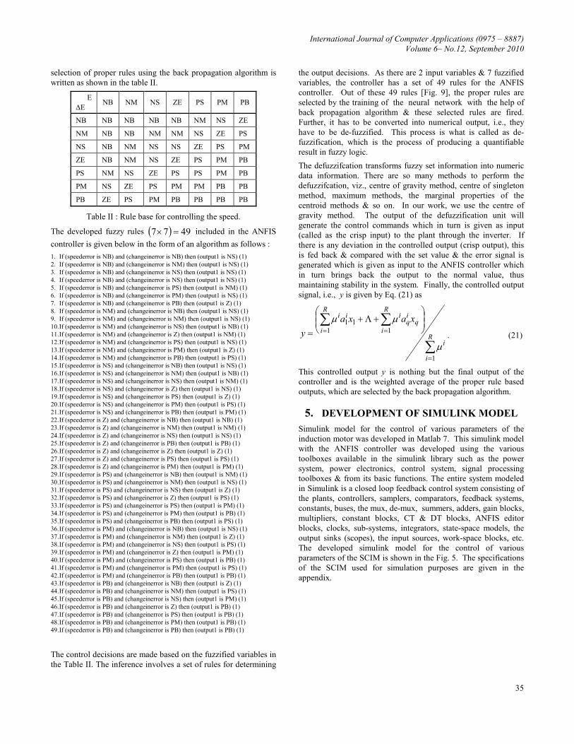
Initially, the fuzzy file where the rules are written with the
incorporation of the T-S control strategy is opened in the Matlab
command window, after which the fuzzy editor (FIS) dialogue
box opens as shown in the Fig. 6. The .fis file
(sugenosevenrules2.fis) is imported using the command window
from the source & then opened in the fuzzy editor dialog box
using the file open command. Once the file is opened, the TS-
fuzzy rules file gets activated as shown in the Fig. 7. Further, the
data is exported to the workspace & the simulations are run for a
specific amount of time (say 3 secs). The fuzzy membership
function editor is then obtained using the view membership
command from the menu bar and this is shown in the Fig. 8. The
written TS-fuzzy rules also can be viewed from the rule view
command, which is presented in the Fig. 9. The rule viewer for
the 2 inputs and 1 output can be observed pictorially in the Fig.
10. Now, after performing all the preliminary operations, the
simulations are run for a period of 3 seconds in Matlab 7 with a
reference speed of 100 rads / sec ( ) π260100 i.e., ×
= 955 rpm
& with a load torque of 2 N-m. Once, the simulation is run, the
various parameters such as speed, flux, torque, currents, slip,
voltage, etc. gets stored in the workspace.
After running the Takagi-Sugeno model, we get the error (x1),
change in error (x2) & an intermediate parameter (y). These 3
parameters, viz., x1, x2 & y are stored in a variable in the
command window. The ‘anfis’ editor is opened in the command
window (Fig. 11). These variables which are in the form of data
in the workspace are loaded into the ‘anfis’ editor (Figs. 12 & 13).
The .fis file is generated next in the ‘anfis’ editor by loading the
data from the workspace (Fig. 14). Once the .fis file is generated,
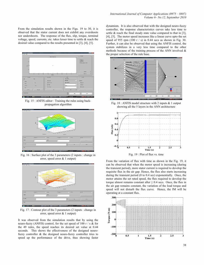
the ‘anfis’ has to be trained properly (Fig. 15) by selecting a
proper algorithm with suitable number of epochs. In our work,
we have used the back-propagation algorithm with a suitable
number of epochs being used for training the rules. This is done
by selecting these 2 items in the ‘train window’ of the ‘anfis’
editor & training the neural network for proper selection of the
rule base. The trained data is further exported to the workspace
using the file-export command. The surface plot for the error
speed & change in error with the output is shown in the Fig. 16.
Also, the contour plot of the same is depicted in the Fig. 17.
The developed ANFIS model structure with 2 input neurons & 1
output neuron along with 4 hidden layers (input membership
function, rule base, membership function, and aggregated output)
are shown in the Fig. 18. The training of the neural network by
using the fuzzy rule base for the selection of the proper & optimal
rule is taken care of by the designed ANFIS controller. Note that
7 by 7 rules are used in the hidden layers. The neuron 1 is
connected to 7 fuzzy rules & the neuron 2 is also connected to the
7 fuzzy rules. The hidden layers contains 49-49 neurons to deal
the problem (for selection of the proper rule base, because the rule
base are written randomly in fuzzy, the neural network selects the
right optimal rule base to fire). The 2 input neurons, viz., the
error, change in error is given as input to the 1st hidden layer of
the ANN as shown in the Fig. 18. This 1st hidden layer deals with
various input membership functions. In the 2nd & 3rd hidden
layer, the set of 49 fuzzy rules are properly identified by training
& the set of optimal rules are selected. These set of optimum
rules are available at the 4th hidden layer. Out of the 49 rules, the
optimal rules are fired here & the de-fuzzified output is obtained
as the output neuron. The de-fuzzified output is further used to
generate the firing pulse to be applied to the inverter bridge,
which is further used to control the speed of the IM drive.
Fig. 6 : FIS editor with 1 input
Fig. 7 : FIS editor with 2 inputs & 1 output ; Importing of the .fis
file from the source
International Journal of Computer Applications (0975 – 8887)
Volume 6– No.12, September 2010
37
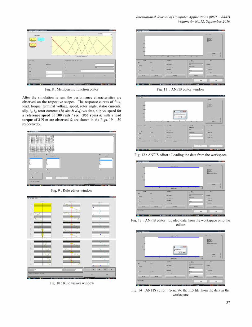
Fig. 8 : Membership function editor
After the simulation is run, the performance characteristics are
observed on the respective scopes. The response curves of flux,
load, torque, terminal voltage, speed, rotor angle, stator currents,
slip, id, iq, rotor currents (3φ abc & d-q) v/s time, slip vs. speed for
a reference speed of 100 rads / sec (955 rpm) & with a load
torque of 2 N-m are observed & are shown in the Figs. 19 - 30
respectively.
Fig. 9 : Rule editor window
Fig. 10 : Rule viewer window
Fig. 11 : ANFIS editor window
Fig. 12 : ANFIS editor : Loading the data from the workspace
Fig. 13 : ANFIS editor : Loaded data from the workspace onto the
editor
Fig. 14 : ANFIS editor : Generate the FIS file from the data in the
workspace
International Journal of Computer Applications (0975 – 8887)
Volume 6– No.12, September 2010
38
From the simulation results shown in the Figs. 19 to 30, it is
observed that the stator current does not exhibit any overshoots
nor undershoots. The response of the flux, slip, torque, terminal
voltage, speed, currents, etc. takes lesser time to settle & reach the
desired value compared to the results presented in [3], [4], [5].
Fig. 15 : ANFIS editor : Training the rules using back-
propagation algorithm
Fig. 16 : Surface plot of the 3 parameters (2 inputs : change in
error, speed error & 1 output)
Fig. 17 : Contour plot of the 3 parameters (2 inputs : change in
error, speed error & 1 output)
It was observed from the simulation results that by using the
neuro-fuzzy (ANFIS) control, for the set speed of 100 r / s & for
the 49 rules, the speed reaches its desired set value at 0.44
seconds. This shows the effectiveness of the designed neuro-
fuzzy controller & the designed neuro-fuzzy controller tries to
speed up the performance of the drive, thus showing faster
dynamism. It is also observed that with the designed neuro-fuzzy
controller, the response characteristics curves take less time to
settle & reach the final steady state value compared to that in [3],
[4], [5]. The motor speed increases like a linear curve upto the set
speed of 955 rpm (100 r / s) in 0.44 secs as shown in Fig. 30.
Further, it can also be observed that using the ANFIS control, the
system stabilizes in a very less time compared to the other
methods because of the training process of the ANN involved &
the proper selection of the rule base.
Fig. 18 : ANFIS model structure with 2 inputs & 1 output
showing all the 5 layers in the ANN architecture
0 0.5 1 1.5 2 2.5 3-0.2
0
0.2
0.4
0.6
0.8
1
Time (s)
Flux (wb)
Fig. 19 : Plot of flux vs. time
From the variation of flux with time as shown in the Fig. 19, it
can be observed that when the motor speed is increasing (during
the transient period), more stator current is required to develop the
requisite flux in the air gap. Hence, the flux also starts increasing
during the transient period (0 to 0.4 sec) exponentially. Once, the
motor attains the set rated speed, the flux required to develop the
torque almost remains constant after ≥ 0.4 secs. Once, the flux in
the air gap remains constant, the variation of the load torque and
speed will not disturb the flux curve. Hence, the IM will be
operating at a constant flux.
0 0.5 1 1.5 2 2.5 3-200
-100
0
100
200
300
Time (s)
Torque (N-m)
International Journal of Computer Applications (0975 – 8887)
Volume 6– No.12, September 2010
39
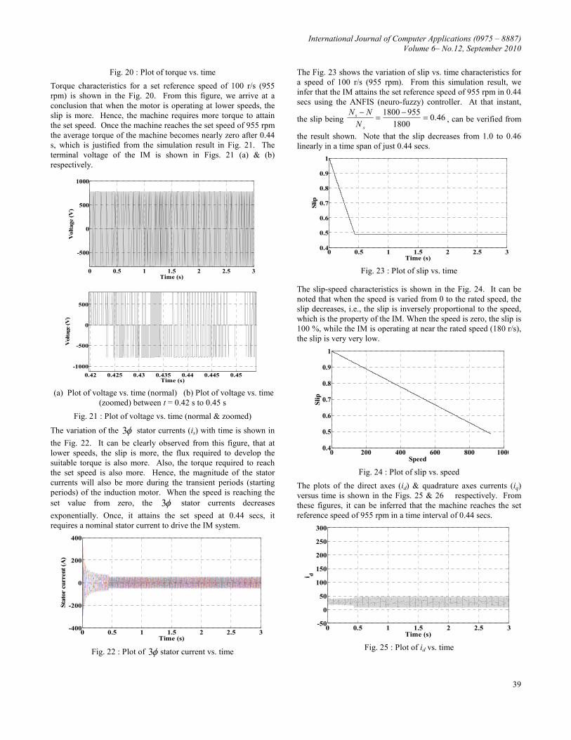
Fig. 20 : Plot of torque vs. time
Torque characteristics for a set reference speed of 100 r/s (955
rpm) is shown in the Fig. 20. From this figure, we arrive at a
conclusion that when the motor is operating at lower speeds, the
slip is more. Hence, the machine requires more torque to attain
the set speed. Once the machine reaches the set speed of 955 rpm
the average torque of the machine becomes nearly zero after 0.44
s, which is justified from the simulation result in Fig. 21. The
terminal voltage of the IM is shown in Figs. 21 (a) & (b)
respectively.
0 0.5 1 1.5 2 2.5 3
-500
0
500
1000
Time (s)
Voltage (V)
0.42 0.425 0.43 0.435 0.44 0.445 0.45
-1000
-500
0
500
Time (s)
Voltage (V)
(a) Plot of voltage vs. time (normal) (b) Plot of voltage vs. time
(zoomed) between t = 0.42 s to 0.45 s
Fig. 21 : Plot of voltage vs. time (normal & zoomed)
The variation of the φ3 stator currents (is) with time is shown in
the Fig. 22. It can be clearly observed from this figure, that at
lower speeds, the slip is more, the flux required to develop the
suitable torque is also more. Also, the torque required to reach
the set speed is also more. Hence, the magnitude of the stator
currents will also be more during the transient periods (starting
periods) of the induction motor. When the speed is reaching the
set value from zero, the φ3 stator currents decreases
exponentially. Once, it attains the set speed at 0.44 secs, it
requires a nominal stator current to drive the IM system.
0 0.5 1 1.5 2 2.5 3-400
-200
0
200
400
Time (s)
Stator current (A)
Fig. 22 : Plot of φ3 stator current vs. time
The Fig. 23 shows the variation of slip vs. time characteristics for
a speed of 100 r/s (955 rpm). From this simulation result, we
infer that the IM attains the set reference speed of 955 rpm in 0.44
secs using the ANFIS (neuro-fuzzy) controller. At that instant,
the slip being 46.01800
9551800=
−=
−
s
s
N
NN, can be verified from
the result shown. Note that the slip decreases from 1.0 to 0.46
linearly in a time span of just 0.44 secs.
0 0.5 1 1.5 2 2.5 30.4
0.5
0.6
0.7
0.8
0.9
1
Time (s)
Slip
Fig. 23 : Plot of slip vs. time
The slip-speed characteristics is shown in the Fig. 24. It can be
noted that when the speed is varied from 0 to the rated speed, the
slip decreases, i.e., the slip is inversely proportional to the speed,
which is the property of the IM. When the speed is zero, the slip is
100 %, while the IM is operating at near the rated speed (180 r/s),
the slip is very very low.
0 200 400 600 800 10000.4
0.5
0.6
0.7
0.8
0.9
1
Slip
Speed
Fig. 24 : Plot of slip vs. speed
The plots of the direct axes (id) & quadrature axes currents (iq)
versus time is shown in the Figs. 25 & 26 respectively. From
these figures, it can be inferred that the machine reaches the set
reference speed of 955 rpm in a time interval of 0.44 secs.
0 0.5 1 1.5 2 2.5 3-50
0
50
100
150
200
250
300
Time (s)
i d
Fig. 25 : Plot of id vs. time
International Journal of Computer Applications (0975 – 8887)
Volume 6– No.12, September 2010
40
0 0.5 1 1.5 2 2.5 3-400
-300
-200
-100
0
Time (s)
i q
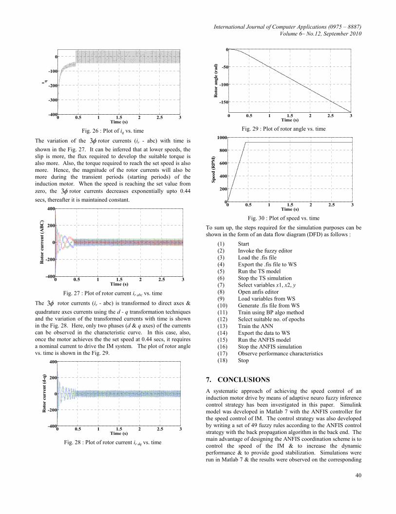
Fig. 26 : Plot of iq vs. time
The variation of the φ3 rotor currents (ir - abc) with time is
shown in the Fig. 27. It can be inferred that at lower speeds, the
slip is more, the flux required to develop the suitable torque is
also more. Also, the torque required to reach the set speed is also
more. Hence, the magnitude of the rotor currents will also be
more during the transient periods (starting periods) of the
induction motor. When the speed is reaching the set value from
zero, the φ3 rotor currents decreases exponentially upto 0.44
secs, thereafter it is maintained constant.
0 0.5 1 1.5 2 2.5 3-400
-200
0
200
400
Time (s)
Rotor current (ABC)
Fig. 27 : Plot of rotor current ir abc vs. time
The φ3 rotor currents (ir - abc) is transformed to direct axes &
quadrature axes currents using the d - q transformation techniques
and the variation of the transformed currents with time is shown
in the Fig. 28. Here, only two phases (d & q axes) of the currents
can be observed in the characteristic curve. In this case, also,
once the motor achieves the the set speed at 0.44 secs, it requires
a nominal current to drive the IM system. The plot of rotor angle
vs. time is shown in the Fig. 29.
0 0.5 1 1.5 2 2.5 3-400
-200
0
200
400
Time (s)
Rotor current (d-q)
Fig. 28 : Plot of rotor current ir dq vs. time
0 0.5 1 1.5 2 2.5 3
-150
-100
-50
0
Time (s)
Rotor angle (rad)
Fig. 29 : Plot of rotor angle vs. time
0 0.5 1 1.5 2 2.5 30
200
400
600
800
1000
Time (s)Speed (RPM)
Fig. 30 : Plot of speed vs. time
To sum up, the steps required for the simulation purposes can be
shown in the form of an data flow diagram (DFD) as follows :
(1) Start
(2) Invoke the fuzzy editor
(3) Load the .fis file
(4) Export the .fis file to WS
(5) Run the TS model
(6) Stop the TS simulation
(7) Select variables x1, x2, y
(8) Open anfis editor
(9) Load variables from WS
(10) Generate .fis file from WS
(11) Train using BP algo method
(12) Select suitable no. of epochs
(13) Train the ANN
(14) Export the data to WS
(15) Run the ANFIS model
(16) Stop the ANFIS simulation
(17) Observe performance characteristics
(18) Stop
7. CONCLUSIONS
A systematic approach of achieving the speed control of an
induction motor drive by means of adaptive neuro fuzzy inference
control strategy has been investigated in this paper. Simulink
model was developed in Matlab 7 with the ANFIS controller for
the speed control of IM. The control strategy was also developed
by writing a set of 49 fuzzy rules according to the ANFIS control
strategy with the back propagation algorithm in the back end. The
main advantage of designing the ANFIS coordination scheme is to
control the speed of the IM & to increase the dynamic
performance & to provide good stabilization. Simulations were
run in Matlab 7 & the results were observed on the corresponding
International Journal of Computer Applications (0975 – 8887)
Volume 6– No.12, September 2010
41
scopes. The characteristic curves of speed, torque, current, flux,
slip, load, etc. vs. time were observed. The outputs take less time
to stabilize, which can be observed from the simulation results.
Due to the incorporation of the ANFIS controller in loop with the
plant, it was observed that the motor reaches the rated speed very
quickly in a lesser time compared to the Mamdani method [3].
The main advantages of the ANFIS scheme being, it is
computationally efficient, works well with linear techniques,
optimization & adaptive techniques. The developed control
strategy is not only simple, but also reliable and may be easy to
implement in real time applications using some interfacing cards
like the dSPACE, data acquisition cards, TMSDSP cards, NI
cards, etc. for control of various parameters. This can also be
combined with expert systems & rough sets for other applications.
The ANFIS also can be used with systems handling more complex
parameters. Another advantage of the ANFIS being the speed of
operation of ANFIS is much faster than the other control
strategies; the tedious task of training of membership functions is
done in ANFIS. Collectively, these results show that the ANFIS
controller provides faster settling times, has very good dynamic
response & good stabilization compared to the Mamdani-fuzzy
control scheme [3].
Abbreviations
AC Alternating Current
AI Artificial Intelligence
ANFIS Adaptive Neuro Fuzzy Inference System
ANN Artificial Neural Networks
BP Back Propagation
DC Direct Current
DSP Digital Signal Processor
DTC Direct Torque Control
DOF Degree Of Freedom
FIS Fuzzy Inference System
FLC Fuzzy Logic Controller
FNN Fuzzy Neural Networks
FOC Field Oriented Control
IM Induction Motor
IEEE Inst. of Elect. & Electronics Engg.
MRAC Model Reference Adaptive Control
MF Membership Function
Matlab Matrix Laboratory
NN Neural Network
NI National Instruments
PI Proportional Integrator
PD Proportional Derivative
PID Proportional Integral Derivative
PWM Pulse Width Modulation
SCIM Squirrel Cage Induction Motor
SMC Sliding Mode Control
SVPWM Space Vector Pulse Width Modulation
TS Takagi Sugeno
Nomenclatures & Symbols
φ Phase
s Laplace domain
z Discrete domain
d Direct axis variable
q Quadrature axis variable
Vsd Direct axis stator voltage
Vsq Quadrature axis stator voltage
Vrd Direct axis rotor voltage
Vrq Quadrature axis rotor voltage
isd Direct axis stator current
isq Quadrature axis stator current
ird Direct axis rotor current
irq Quadrature axis rotor current
sdφ Direct axis stator flux linkages
rdφ Quadrature axis stator flux linkages
sdφ Direct axis rotor flux linkages
sdφ Quadrature axis rotor flux linkages
t Time
Lr Rotor inductance
Ls Stator inductance
Lm Mutual inductance
ω Angular frequency
Tem Electromagnetic torque
P Power
TL Load torque
Jeq Equivalent Moment of Inertia
Vm Maximum value of AC voltage
VAn Voltage of phase-A to neutral
VBn Voltage of phase-B to neutral
VCn Voltage of phase-C to neutral
VDC DC voltage
Appendix
A1. Squirrel Cage Induction Motor (SCIM) specs :
50 HP, 1800 rpm, 460 V, 60 Hz., 3-Phase
2 pair of poles, Squirrel Cage type IM
H108.0,087.0 3−×=Ω= ss LR
mH 8.0,228.0 =Ω= rr LR
mH7.34=mL 2.662.1 mkgJ =
REFERENCES
[1]. A.Iqbal, “Analysis of space vector pulse width modulation
for a five phase voltage source inverter” IE (I) journal-EL,
Vol. 89, Issue 3, pp. 8-15, Sept. 2008.
[2]. Allouche Moez, Souissi Mansour, Chaabane Mohamed
and Mehdi Driss, “Takagi-Sugeno Fuzzy Control of
Induction Motor”, Proc. Int. Journal of Electrical and
Electronics Engg., Vol. 2, Issue 1, 2009.
[3]. Ashok Kusagur, S. F. Kodad, B V. Sankar Ram, “AI
based design of a fuzzy logic scheme for speed control of
induction motors using SVPWM technique”, Int. Jr.
Comp. Sci. & Network Security, Vol. 9, No. 1, pp. 74 -
80, Jan. 2009.
[4]. Ashok Kusagur, S.F.Kodad, B.V. Sankar Ram,
“Modelling of Induction Motor & Control of Speed Using
Hybrid Controller Technology”, Proc. Int. Journal of
Theoretical Information & Technology (JATIT), Vol. 10,
issue 2, pp. 117-126, Dec. 2009,
International Journal of Computer Applications (0975 – 8887)
Volume 6– No.12, September 2010
42
[5]. Ashok Kusagur, S.F.Kodad, B.V. Sankar Ram, “Novel
design of a Takagi-Sugeno fuzzy strategy for induction
motor speed control”, Paper accepted for publication in
Journal of Electrical Systems, Vol. 6, issue 2, Jun. 2010.
[6]. Ashok Kusagur, Jagadish Pujar, “Design of A VAR
Compensator”, Proc. International Conference on Trends
in Intelligent Electronic Systems, Satyabhama University,
Chennai, Tamil Nadu, India, Nov. 12 - 14, 2007.
[7]. Aware M.V., Kothari A.G., Choube S.O., “Application of
adaptive neuro-fuzzy controller (ANFIS) for voltage
source inverter fed induction motor drive”, The Third
International Electronics and Motion Control Conference
- IPEMC 2000, Vol. 2, pp. 935-939, 2000.
[8]. Barrero F., A. Gonziilez, A. Torralba, E. GalvBn and L.G.
Franquelo, “Speed Control of Induction Motors Using a
Novel Fuzzy-Sliding Mode Structure”, IEEE Conf. paper,
pp. 1073-1078.
[9]. Ben-Brahim L., “Improvement of the stability of the V/f
controlled induction motor drive systems”, IEEE
Proceedings of the 24th Annual Conference, Vol. 2, pp.
859-864, 1998.
[10]. Bimal K Bose, Nitin R Patel, Kaushik Rajashekara, “A
neuro-fuzzy based on-line efficiency optimization control
of a stator flux oriented direct vector controller IM drive”,
IEEE Trans. Industrial Electronics, Vol. 44, No. 2, pp.
270-273, Apr. 1997.
[11]. Bose B.K., Modern Power Electronics and AC
Drives, Pearson Education, Inc., India, 2002.
[12]. Cao S.G., Rees N.W. and Feng G., “Analysis and
design of fuzzy control systems using dynamic fuzzy
state space Models”, Proc. of the Trans. on IEEE
Trans. Fuzzy Syst., Vol. 7, No. 2, pp. 192–199,
1999.
[13]. Carlos A. Martins, Adriano S. Carvalho, “Technological
Trends in Induction Motor Electrical Drives”, IEEE Porto
Power Tech Conference, Vol. 2, Sep. 2001.
[14]. Chen C-Li and Chang M-Hui, “Optimal design of
fuzzy sliding mode control: A comparative study”,
Fuzzy Sets Syst., Vol. 93, pp. 37–48, 1998.
[15]. Chen J.Y. and C.C. Wong, “Implementation of the Takagi-
Sugeno model-based fuzzy control using an adaptive gain
controller”, IEE Proc. - Control Theory Appl., Vol. 147,
No. 5, pp. 509 – 514, Sept. 2000.
[16]. Chen T.C., and Hsu J.U., “A fuzzy sliding mode controller
for induction motor position control”, IECON’94., 20th
Int. Conf on Industrial Electronics, Control and
Instrumentation, Vol. 1, pp. 44-49, 1994.
[17]. Chong. Lin, Q.G. Wang and T.H. Lee, “Output tracking
control for nonlinear via T-S fuzzy model approach, Proc.
IEEE Trans. systems. Cybernetics, Vol. 36, No. 2, 2006.
[18]. Chuen Chien Lee, “Fuzzy Logic in Control Systems :
Fuzzy Logic controller –Part 2”, IEEE, 1990.
[19]. Chuen Chien Lee, “Fuzzy Logic in Control Systems:
Fuzzy Logic controller–Part 1”, IEEE, 1990.
[20]. Consoli A, E. Cerruto, A. Raciti, A. Testa, “Adaptive
vector control of induction motor drives based on a neuro
fuzzy approach”, IEEE Paper, pp. 225-232, 1994.
[21]. Ernesto Araujo, “Improved Takagi-Sugeno Fuzzy
Approach”, IEEE International Conference on Fuzzy
Systems (FUZZ 2008), pp. 1154-1158, 2008.
[22]. Faa Jeng Lin, Rong Jong Wai, “Adaptive fuzzy neural
network control for IM spindle motor drive”, IEEE Trans.
Energy Conversion, Vol. 17, No. 4, pp. 507-513, Dec.
2002.
[23]. Farzan Rashidi, “Sensorless Speed Control of Induction
Motor Derives Using a Robust and Adaptive Neuro-Fuzzy
Based Intelligent Controller”, IEEE International
Conference an Industrial Technology (ICIT), pp. 617-627,
2004.
[24]. Giovanna Castellano, “A neuro-fuzzy methodology for
predictive modelling”, Ph.D. Thesis, Dept. of Comp. Sci.,
Univ. of Bari, 2000.
[25]. Grabowski, P.Z. Kazmierkowski, M.P. Bose, B.K.
Blaabjerg, F. , “A simple direct-torque neuro-fuzzy control
of PWM-inverter-fed induction motor drive”, IEEE Trans.
on Industrial Electronics, Vol. 47, Issue 4, pp. 863 – 870,
Aug 2000.
[26]. H. Rehman and R. Dhaouadi, “A fuzzy learning-sliding
mode controller for direct field-oriented induction
machinese”, Neuro-computing, Vol. 71, pp. 2693–2701,
2008.
[27]. Haider A. F. Mohamed, E. L. Lau, S. S. Yang, M.
Moghavvemi, “Fuzzy-SMC-PI Flux and Speed Control for
Induction Motors”, Proc. of RAM-2008, pp. 325-328,
2008.
[28]. Hassan Baghgar Bostan Abad, Ali Yazdian Varjani,
Taheri Asghar, “Using Fuzzy Controller in Induction
Motor Speed Control withConstant Flux”, Proc. of world
academy of science, engineering and technology, Vol. 5,
ISSN 1307-6884, April 2005.
[29]. Henrik Mosskull, Johann Gali´c, and Bo Wahlberg,
“Stabilization of Induction Motor Drives With Poorly
Damped Input Filters”, IEEE Transactions on Industrial
Electronics, Vol. 54, No. 5, pp. 2724-2734, Oct. 2007.
[30]. http://www.wikipedia.org
[31]. Iman Zamani, Masoud Shafie, “Fuzzy Affine Impulsive
Controller”, Fuzzy IEEE 2009, Korea, pp. 361-366, Aug.
20-24, 2009.
[32]. Jagdish Pujar, Ashok Kusagur, S.F. Kodad, T.C.
Manjunath, “Fuzzy Logic Based Flexible Multi-Bus
Voltage Control of Power Systems”, Proc. of the 31st
National Systems Conference, NSC-2007, MIT-MAHE
Campus, Manipal - 576104, Karnataka, India, 14-15, Nov.
2007.
[33]. Jinjie Huang, Shiyong Li, Chuntao Man, “A TS type of
fuzzy controller based on process of input output data”,
Proc. of 42nd IEEE Conf. on Decision & Control
(CDC’03), Hawai, USA, pp. 4729-4734. Dec. 2003.
[34]. Kazuo Tanaka, Hua O. Wang, “Fuzzy Control Systems
Design and Analysis: A Linear Matrix Inequality
Approach” John Wiley & Sons, Inc., USA. 2002.
[35]. Khiar D., “Robust takagi-sugeno fuzzy control of a spark
ignition engine”, Control Engg. Practice, 2007.
[36]. Kim D.H., Kim H.S., Kim J.M., Won C.Y. and Kim S.C.,
“Induction motor servo system using variable structure
control with fuzzy sliding surface”, IEEE Int. Conf.
International Journal of Computer Applications (0975 – 8887)
Volume 6– No.12, September 2010
43
Industrial Electronics, Control, and Instrumentation, Vol.
2, pp. 977-982, 1996.
[37]. Liu X., and S. Zhong, “T–S fuzzy model-based impulsive
control of chaotic systems with exponential decay rate”,
Physics Letters A, Vol. 370, pp. 260–264, 2007.
[38]. M. Sugeno and K. Tanaka, “Successive
identification of a fuzzy model and its applications to
prediction of a complex system”, Proc. Fuzzy Sets
and Systems, Vol. 42, pp. 315-334, 1992.
[39]. Mihoub M, B. Mazari, S. Fasla, “Neuro-fuzzy controller
used to control the speed of an induction motor”,
Conference paper.
[40]. Mir. S.A and Malik. E. Elbuluk, “Fuzzy controller for
Inverter fed Induction Machines”, IEEE Transactions on
Industry Applications, Vol. 30, pp. 78-84, 1994.
[41]. Mokhtar Zerikat, Sofiane CHekroun, “High performance
speed tracking of IM using an adaptive fuzzy NN control”,
Int. Jr. Sciences & Techniques of Auto. Contr. &
Computer Engg., IJ-STA Special Issue, CEM, pp. 516-
531, Dec. 2008.
[42]. Mouloud Azzedine Denai, Sid Ahmed Attia, “Fuzzy
and Neural Control of an Induction Motor”, Proc.
Int. J. Appl. Math. Comput. Sci., Vol.12, No. 2, pp.
221–233, 2002.
[43]. Nasir Uddin M., Hao Wen, “Model Reference Adaptive
Flux Observer Based Neuro-Fuzzy Controller for
Induction Motor Drive”, IAS-2005, IEEE paper, pp. 1279
– 1285.
[44]. Peter Vas, “Sensorless Vector and Direct Torque control”,
Oxford University press, 1998.
[45]. R. Arulmozhiyal, K. Baskaran, “Space Vector Pulse Width
Modulation Based Speed Control of Induction Motor
using Fuzzy PI Controller”, Proc. of the International
Journal of Computer and Electrical Engg., Vol. 1, No. 1,
pp. 98-103, April 2009.
[46]. Ramón C. Oros, Guillermo O. Forte, Luis Canali, “Scalar
Speed Control of a d-q Induction Motor Model Using
Fuzzy Logic Controller”, Conf. paper.
[47]. Satean Tunyasrirut, Tianchai Suksri, and Sompong Srilad,
“Induction Motor using Space Vector Pulse Width
Modulation”, Proc. of the World Academy of Science,
Engineering Fuzzy Logic Control for a Speed Control of
And Technology, Vol. 21, pp. 71 - 77, Jan. 2007.
[48]. Shaw A. and Doyle F., “Multivariable non-linear
control application for a high purity distillation
column using a recurrent dynamic neuron model”, J.
Process Contr., Vol. 7, No. 4, pp. 255–268, 1997.
[49]. Sivanandam S.N., S. Sumathi and S.N. Deepa,
“Introduction to fuzzy logic using Matlab”, Springer-
Verlarg Publications, 2007.
[50]. Sugeno M. and G. T. Kang, “Structure identification
of fuzzy model”, Proc. on the Fuzzy Sets and
Systems, Vol. 28, pp. 15-33, 1988.
[51]. Takagi T. and M. Sugeno, “Fuzzy identification of
system and its applications to modeling and control”,
Proc. IEEE Trans. on System Man and Cybernetics,
Vol. SMC-15, No. 1, pp. 116-132, 1985.
[52]. Trzynadlowski A.M., “The Field Orientation
Principle in Control of Induction Motors”, Kluwer
Pub., Dordrecht, 1994.
[53]. Vas P., “Vector Control of AC Machines”, Oxford
University Press, London, UK, 1990.
[54]. Xie Keming, TY Lin, Zhang Jianwei, “The Takagi-Sugeno
fuzzy model identification method of parameter varying
systems”, Proc. Rough Sets Current Trends Conf.,
RSCTC’98, Warsaw, Poland, Jun. 22-26, 1998.
[55]. Yasuhiko Dote, Yuji Fujino, Amin Suyitno, “Neuro fuzzy
robust controllers for AC drive systems”, IEEE Conf.
paper, pp. 2311-2316, 1993.
[56]. Yu Zhang, Zhenhua Jiang, Xunwei Yu, “Indirect Field-
Oriented Control of Induction Machines Based on
Synergetic Control Theory”, IEEE Int. Conf. on Power
and Energy Society General Meeting - Conversion and
Delivery of Electrical Energy in the 21st Century, 2008,
pp. 20-24, 1 – 7, Jul. 2008.
[57]. Zdenko Kovaccic and Stjepan Bogdan, “Fuzzy Controller
design Theory and Applications”, Taylor & Francis
Group International, 2002.
[58]. Zhang X., et. al., “Impulsive stability of chaotic systems
represented by T-S model”, Proc. Chaos, Solutions &
Fractals, doi:10.1016/j.chaos.2008.07.052, 2008.
AUTHOR PROFILE
Ashok Kusagur was born in the year 1970 and he received the
B.E. degree in Electrical & Electronics Engg. (EEE) from Bapuji
Institute of Engg. & Tech. (BIET), Davanagere, Karnataka, India
from Kuvempu University in the year 1996 and the M.Tech.
Degree in Power Electronics from PDA College of Engg.,
Gulbarga, Karnataka, India from the VTU in the year 2001. He
has got a teaching experience of nearly 12 years. Currently, he is
working as Professor & Head of the Department of Electronics &
Communications Engg. in HMS Institute of Technology, Tumkur,
Karnataka, India in the Dept. of Electronics & Communications
Engg. & simultaneously doing his Ph.D. (Research) in Electrical
& Electronics Engg. from the prestigious Jawaharlal Nehru
Technological University (JNTU), Hyderabad, Andhra Pradesh,
India. He has published more than a number of papers in various
national & international conferences & journals. His areas of
interests are neural networks, fuzzy logic, artificial intelligence,
power electronics, field theory, networks, control systems,
Matlab, etc.
Dr. S. F. Kodad received the B.E. degree in EEE from STJ
Institute of Technology, Ranebennur, Karnataka, India from
Karnataka University and the M.Tech. degree in Energy Systems
Engg. from JNTU, Hyderabad, India in the year 1992. He
received his Ph.D. degree in Electrical Engg. from JNTU,
Hyderabad, India in the year 2004. He has got a teaching
experience of nearly 20 years. Currently, he is working as Director
in Krishnamurthy Institute of Technology, Hyderabad, Andhra
Pradesh, India. He has published a number of papers in various
national & international journals & conferences & done a number
of in-house & industry projects. He has also presented a number
of guest lectures and various seminars and participated in a
number of courses, seminars, workshops, symposiums in the
various parts of the country in different institutions and also
conducted a few courses. He is also guiding a number of Ph.D

International Journal of Computer Applications (0975 – 8887)
Volume 6– No.12, September 2010
44
students. His area of interests are neural networks, fuzzy logic,
power electronics, power systems, artificial intelligence, Matlab,
Renewable energy sources, etc.
Dr. B. V. Sankar Ram received the B.E. degree in Electrical
Engg. from Osmania University & M.E. degree in Power Systems
from Osmania University, Hyderabad, Andhra Pradesh, India. He
received his Ph.D. degree in Electrical Engg. from JNTU,
Hyderabad, India. He obtained Diploma in Candidate
Management Finance. He has got a teaching experience of more
than 20 years.
Currently, he is working as Professor in JNTU College of Engg.
Hyderabad, India in the Dept. of Electrical Engg. He has
published a number of papers in various national & international
journals & conferences & done a number of in-house & industry
projects. He is also guiding a number of Ph.D. students (research
scholars) in various topics of engg. He has specialized in power
systems. His research interests include power system reliability
and Flexible AC Transmission systems, power electronics & it is
applications.


![Design features and research on the neuro-like learning ... · systems based on neuro-fuzzy logic: - an adaptive neuro-fuzzy inference system (ANFIS) [15]; - an adaptive neurofuzzy](https://img.pdfslide.net/doc/110x75/605ac52cb6bd5c4a7f031940/design-features-and-research-on-the-neuro-like-learning-systems-based-on-neuro-fuzzy.jpg)