Embed Size (px)
Citation preview

Modeling Electrical Systems
Dr. Nhut Ho
ME584
chp4 1

Agenda
• Basic Electrical Elements
• Passive Circuit Analysis
• Active Circuit Analysis
• Case Study: A Speaker Model
• Active Learning: Pair-share Exercises, Case Study
chp4 2

Basis Electrical Elements
chp4 3

Electrical System
• Composed of resistors, capacitors, inductors, transistors, amplifiers, power supplies– Passive circuits: respond to applied voltage or current and
do not have any amplifiers – Active circuits: made of transistors and/or amplifiers,
require active power source to work
• Basic quantities– Charge q [coulomb] = 6.24x10¹⁸ electrons– Current i [ampere] = dq/dt– Voltage e [Volt] = dw/dq– Energy or Work w [joule]– Power p [watt] = e x i = dw/dt
chp4 4

Units and Representations for Common Electrical Quantities
chp4 5

General Model Structure for Mechanical System
Chap4 6

General Model Structure for Electrical System
Chap4 7

Equivalent Circuit for Spring-Mass-Dashpot Systems
chp4 8

Resistance
• Resistance behavior is between insulator and conductors, allowing a predictable restriction of electron flow
• Power dissipated =
• Resistance
– A: cross section are of wire
– l: length of wire
– ρ: resistivity of material
chp4 9

Capacitance
• Capacitor stores electrons on 2 parallel plates separated by an insulating dielectric material in an electric field
• Energy stored in capacitor
• Capacitance
– A: area of plates
– D: spacing between plates
– ϵ:permittivity of the dielectric
chp4 10
or

Inductance
• Inductance relates voltage induced to time rate of change of magnetic field
• Faraday’s law:
where φ is the magnetic flux, φ = Li
• Energy stored:
• Inductance:where A= wire cross section area, l = wire length, n =
number of turns, μm =permeability of magnetic circuit
chp4 11

Impedance
• Impedance Z: instantaneous ratio of voltage difference to current
• Impedance of common circuit elements
– Resistive: Zr = R (not dynamic)
– Capacitive: Zc = 1/CD
– Inductive: ZL=LD
Where D= differential operator d/dt,
1/D = integrator operator
chp4 12

Ideal and Non-Ideal Sources
Voltage Source Current Source
Ideal
Non-Ideal
Battery
chp4 13
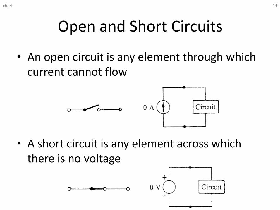
Open and Short Circuits
• An open circuit is any element through which current cannot flow
• A short circuit is any element across which there is no voltage
chp4 14

Series and Parallel Impedance Combinations
chp4 15
R
L
C

Laws for Passive Circuit Analysis
chp4 16

Techniques for Passive Circuit Analysis for Classical Deriving Differential Equations
1. Draw circuit schematic and label components (e.g., R1, R2, C1, L1…)
2. Assign voltage at each node (e.g., e1, e2)
3. Assign current in each component (e.g., i1, i2, ..) and show positive current direction with arrows
4. Write equation for current for each component (e.g., iR1 = (e1-e2)/R1 or iC1 = CDe1 )
5. Write node equations for each significant node (not connected to voltage or current source)
6. Substitute component equations into node equations and reduce results to a single differential equation with output and input variables
chp4 17

Example 1: Voltage Divider chp4 18
Evaluate e1

Example 2: Resistor Circuit
chp4 19
• Calculate the amount of power dissipated in resistor R3 in the circuit shown below
• Solution:

Example 3: Pair-Share ExerciseSeven-Resistor Circuit
• The resistive circuit shown consists of a voltage source connected to a combination of seven resistors. The output is voltage e0. Find the equivalent resistance Req of the seven-resistor combination and evaluate e0.
chp4 20

Example 3: Pair-Share ExerciseSeven-Resistor Circuit
chp4 21
Apply voltage divider equation repeatedly

Example 4: Dual RC Circuit chp4 22
• Write the modeling equations for circuit (a)
• Derive the differential equation in the form [τD+1]e1=Ge0
• What are the mathematical expressions for time constant τand gain G?
• For circuit (b), is the differential equation for this circuit a product of two RC’s circuit, that is, [τ1D+1][τ2D+1]e2=e0 ?
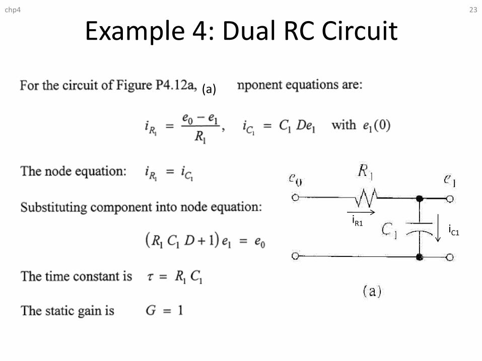
Example 4: Dual RC Circuit chp4 23
(a)
iR1iC1

Example 4: Dual RC Circuit chp4 24
(b)
iR1iC1
iR2
iC2

Example 4: Dual RC Circuit chp4 25