Embed Size (px)
Citation preview
核子工程組核子工程組核子工程組核子工程組1111
Modeling of A Power Conversion System with RELAP5-3D and Associated Application toFeedwater Blowdown Licensing Analysis
for the LungMen ABWR Plant
Prepared by: Thomas K.S. Prepared by: Thomas K.S. Prepared by: Thomas K.S. Prepared by: Thomas K.S. LiangLiangLiangLiang
Institute of Nuclear Energy Research, TaiwanInstitute of Nuclear Energy Research, TaiwanInstitute of Nuclear Energy Research, TaiwanInstitute of Nuclear Energy Research, Taiwan

核子工程組核子工程組核子工程組核子工程組2222
Contents
一、一、一、一、Introduction二、二、二、二、Event Description三、三、三、三、Modeling Description四、四、四、四、Modeling Sensitivity Study五、五、五、五、General Assumptions for
Event Licensing Analysis六、六、六、六、Results七、七、七、七、Conclusions八、八、八、八、Future Work

核子工程組核子工程組核子工程組核子工程組3333
Introduction
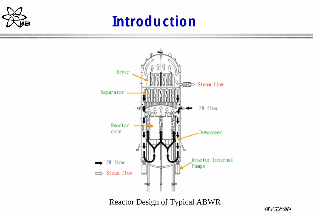
� Conventionally, the limiting break for BWR containment design is the recirculation line break.
� In the ABWR design, the jet pumps driven by the recirculation loops are replaced by the reactor internal pumps (RIPs).
� As a result, the limiting break for ABWR containment design shifts to the Feedwater Line Break (FWLB).
核子工程組核子工程組核子工程組核子工程組4444
Introduction
Reactor Design of Typical ABWR

核子工程組核子工程組核子工程組核子工程組5555
Introduction
� The licensing analysis of FW line break with RELAP5-3D/K , and the RELAP5-3D/K is an Appendix K version of RELAP5-3D.
� To adequately calculate the blowdown flow and enthalpy for the event of FW line inboard break, the BOP modeling scope includes all the necessary components and systems. �Main feedwater system; �Main condainson;�Main steam system�Main turbine system �Turbine driven feedwater pumps

核子工程組核子工程組核子工程組核子工程組6666
Main Steam
HP Turbine LP Turbine
MSR
Generator
HP Heater
LP Heater
OffgasSystem
SJAE
CP
CBP
Con
dens
ate
Dem
iner
aliz
er
Gland Steam Condenser
Con
dens
ate
Polis
hing
Pr
efilt
er
StackOcean
Condenser
TBV
MSV GVMSIV
MD
RFP
TDR
FP C
TDR
FP B
TDR
FP A
LONG PATH RECIR CTRL VALVE N22-ACV-5031
LFC
V N
22-
ACV-
5025
BLOWDOWN VALVE G31-ACV-0024
RFP
BYP
ASS
VALV
E N
22-M
BV-5
042
Feedwater
ISOLATION OUTBOARD VALVE N22-MBV-0001
MBV
-503
8
MBV-5003A
MBV-5003C
MBV-5003B
MBV-5062
Modeling Scope for Feedwater Line Break Analysis

核子工程組核子工程組核子工程組核子工程組7777
Introduction
CDSR
FWHTR#3
NPP4 System Simulation Diagram
Steam
Water
Extraction to MSR RHTR #2
Extraction to MSR RHTR #1
GV
NRV
NRV
CV
GV
GV
GV
CV CV
CV
ISOV
LFCV
ISOV
Extraction to HTR#1
Vent from MSR RHTR #2 Drain Tank
Vent from MSR RHTR #1 Drain Tank
Vent from HTR#1
Drain from HTR#6
Drain from MSR RHTR #2 Drain Tank
Drain from MSR RHTR #1 Drain Tank
ORF
ORF
MSLHeader
Extraction to LP FW HTR
Drain from MSRSeparator Drain Tank
ISOV
HP Turbine MSR
RHTR #1Drain Tank
RHTR #2Drain Tank
SeparatorDrain Tank
LP Turbine
ORF
CP
TDFWP
TDFWP
MDFWP
RPV
FromSea
ToSea
MFPT
FWHTR#4
FWHTR#5
FWHTR#6
FWHTR#2
FWHTR#1
NRV
ORF Vent from HTR#2
CV CV
NRV
CV CV CV
Extraction to HTR#2
GV
GV

核子工程組核子工程組核子工程組核子工程組8888
Event Description
� For the event of FWLB, blowdown flow and enthalpy from both RPV & BOP are the most essential parameters to be calculated.
� The early BOP blowdown flow will be limited by choking at either the break end or the internal venturi.
� The early FW blowdown will drive more extraction steam from MS system to FW heaters.
� As a result of MSIV isolation during the early blowdown stage, the steam supply cannot be maintained and steam pressure will drop rapidly.
� After the run out and coast down of FW pumps, the condensate and booster pumps will continuously pump water from condenser to the break thereafter by conservative assumption.

核子工程組核子工程組核子工程組核子工程組9999
Event Description
� To adequately analyze the break events, all essential phenomena involved in the FW blowdown process need to be adequately simulated. Those phenomena include :� critical flow at the break and the internal venturi,� flashing of FW near the break,� run out and coast down of the FW pumps,� steam extraction to FW heaters and FWP turbines,� flashing of saturated water initially stored inside the FW heater shell
sides and drain tanks,� energy release from saturated water and system metal to the FW, and� cold water transportation from the main condenser to the break.

核子工程組核子工程組核子工程組核子工程組10101010
Modeling Description
� All components of MS and FW systems are modeled and integrated by system piping to form a completed power conversion system.
� Detailed system design data is applied to develop the model for each component and associated piping.
� The simulated initial system conditions at rated state will be compared against associated parameters from Thermal Kit and/or Process Flow Diagram (PFD) of Lungmen plant.
� Totally 299 nodes and 277 junctions are involved in the entire BOP simulation scope.

核子工程組核子工程組核子工程組核子工程組11111111
Modeling Description-FW System Modeling-
� Total of 158 hydraulic volumes and 151 junctions are involved in modeling of the FW system.
� The components of the FW system modeling include :�FW pumps (FWPs) and driving turbines; �FW heaters; �condensate and booster pump; �main condenser; and �system piping.

核子工程組核子工程組核子工程組核子工程組12121212
Modeling Description-FW System Modeling -
TDJ
TDJ
Exhaustfrom MFPT
From Sea
To Sea
TDJ
Drain fromHTR#6
TDJ
Extraction fromLP Turbine#2
Drain from MSRSPRTR Drain Tank
To RPV
Exhaust fromLP Turbine
Vent from HTR#1
ORF
TDJ
ISOV
ISOV
LFCV
ISOVTDV
TDV
TDV
CDSR
601
CP603
HTR#4
TDV
TDFWP647
665
651
673675
TDFWP648
MDFWP649
HTR#5
HTR#2HTR#1
HTR#3
Extraction fromHP Turbine #5
Drain from MSRRHTR #1 Drain Tank
Drain from MSRRHTR #2 Drain Tank
Vent from MSRRHTR #2 Drain Tank
Vent from MSRRHTR #1 Drain Tank
HTR#6
663
Extraction from HPTurbine exhaust
653
ORF
655
Drain toHTR#2
TDJ
TDV
TDJTDJTDJ
Drain fromHTR#2
637
639
Vent from HTR#2
TDJ
Extraction fromLP Turbine#3
TDVDrain fromHTR#3
TDJ
Extraction fromLP Turbine#5
TDVDrain fromHTR#4
TDJ
Extraction fromLP Turbine#6
TDVDrain fromHTR#5
627
629
617
619
607
609
Vent from HTR#3Vent from HTR#4
Vent from HTR#5Vent from HTR#6
661
625 615 605
CV
Drain toHTR#3TDV
CV
Drain toHTR#4TDV
CV
Drain toHTR#5TDV
CV
Drain toHTR#6TDV
CV
TDV Drain toCDSR
CV
611
657
621
613
623
633
643
641
631
659
667
669
644
645
646
635
TDJ
TDV
Drain fromHTR#1
701
702703
706
707 708
709
710
715716
717
718
719
725726
727
728
729
735
737
738
739
736
745
746
747
748
749
750
753
754
751
752
755
756
761
762
764
765
770
771
773
774
781
782
711
712
713
720
721
722
730
731
732
740
741
742
763
766
767
768
772
775
776
777
671
677
783
786 785 784679

核子工程組核子工程組核子工程組核子工程組13131313
Modeling Description-FW System Modeling -
� Pump design curves at run out speed 5350 rpm are used to simulate the pump characteristics.
� Since each FWP is driven by a FWP turbine, the modeling of FWP turbine with a shaft to connect FWP is also included.
� The rotation speed of the whole FWP module will be determined by the angular momentum conservation applied on the shaft connecting associated turbine and pump.
ωττω *fI PTi
dtd
i −−=�

核子工程組核子工程組核子工程組核子工程組14141414
Modeling Description-FW System Modeling -
TDFWP
MFPT465 466GV
To CDSR562562
564564 565565467
561561From MSR 9090190901
6449690196901
6479690296902
635745745 From HTR # 3
651752752
761761736736
ISOVTo HTR # 2
205909205909SHAFT
1000 2000 3000 4000 5000 6000 7000Capacity [m3/hr]
600
700
800
900
1000
Hea
d [m
]
Turbine Driven Feedwater PumpRELAP5-3DOriginal

核子工程組核子工程組核子工程組核子工程組15151515
Modeling Description-FW System Modeling -
Error Analysis of Initial Conditions of Feedwater System at Rated Condition

核子工程組核子工程組核子工程組核子工程組16161616
Modeling Description-FW System modeling -
0 2 4 6 8 10N
-10
-8
-6
-4
-2
0
2
4
6
8
10
Erro
r - P
ress
ure
[%]
HTR1 OutletHTR2 OutletFWP DischargeFWP SuctionHTR4 OutletHTR5 OutletHTR6 OutletCP DischargeMain Condenser
0 2 4 6 8 10N
-10
-8
-6
-4
-2
0
2
4
6
8
10
Erro
r - T
empe
ratu
re [%
]
HTR1 OutletHTR1 InletHTR2 InletHTR3 OutletHTR3 InletHTR4 InletHTR5 InletHTR6 Inlet
Error Analysis of Pressure Distribution Error Analysis of Temperature Distribution
核子工程組核子工程組核子工程組核子工程組17171717
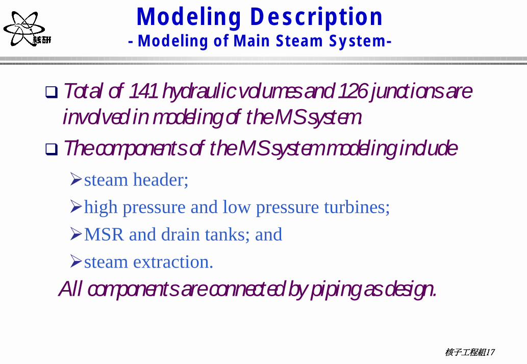
Modeling Description- Modeling of Main Steam System-
� Total of 141 hydraulic volumes and 126 junctions are involved in modeling of the MS system.
� The components of the MS system modeling include �steam header; �high pressure and low pressure turbines; �MSR and drain tanks; and �steam extraction.
All components are connected by piping as design.

核子工程組核子工程組核子工程組核子工程組18181818
Modeling Description- Modeling of Main Steam System-
401MSL
Header
405
403
407
409
411
GV
SP423
From HPTextraciton
To Heater #3
From MSLHeader
CV CV CV
To MSR RHTR#2
extraction
461
M FPT413
extraction
ORF ORF
NRV
To Heater #1
MSR
1st heaterdrain tank1st heaterdrain tank
2nd heaterdrain tank2nd heaterdrain tank
Separatordrain tankSeparatordrain tank
To MSRRHTR#1To MSRRHTR#1
473
NRV
HPTLPT
To CDSR
465
469FromRPV
463
477
481
471
475
479
483
417
415
419
421 4
33
439
443
449
453
455
451
435
441
445
To Heater #1
To Heater #3
To Heater #4
To Heater #5
To Heater #6
467
To Heater #1
To Heater #2
431
437
447
425
427
GV
To CDSR
RHTR#2 RHTR#1501501
502502
503503
504504
505505
506506
507507
508508
511511 512512
513513 516516
519519
514514 517517 520520
522522
532532
533533
534534
535535
515515 518518 521521
536536
540540
541541
542542
543543
544544
545545
546546
547547
550550
551551
552552
553553
554554
555555
556556
557557
561561560560 562562
563563 564564565565
566566 567567
570570
571571574574577577
580580
572572
573573
575575
576576
578578
579579 581581
509509 510510
492
491
493
494
MSIV586586
587587
588588
589589
590590
591591
592592
593593
496
495
497
498
594594
595595
596596
597597
核子工程組核子工程組核子工程組核子工程組19191919
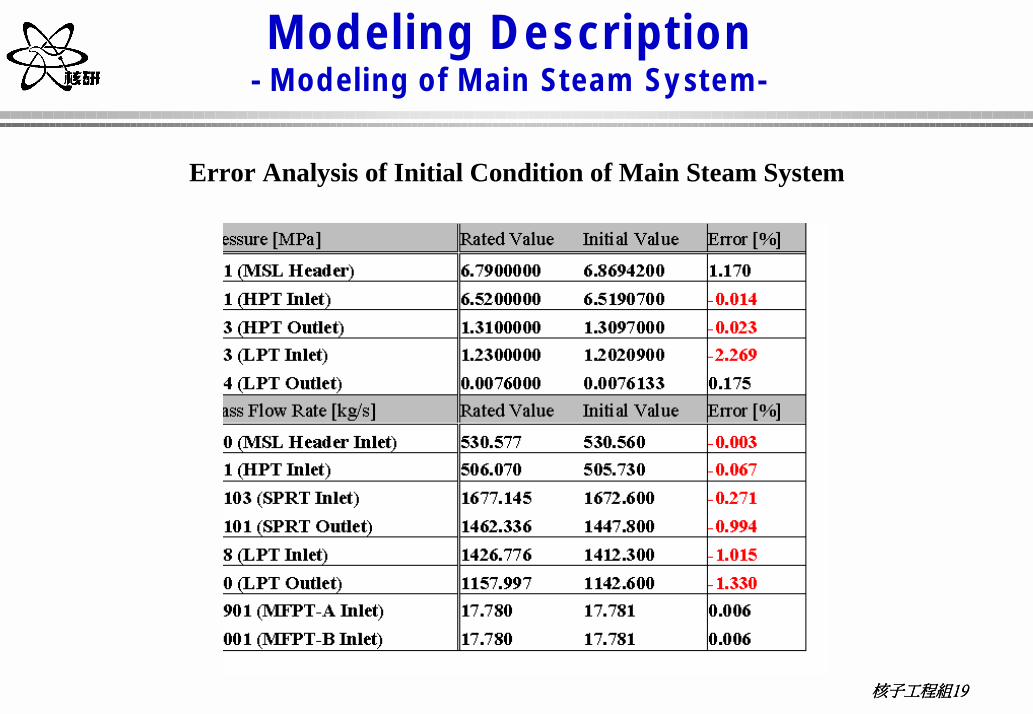
Modeling Description- Modeling of Main Steam System-
Error Analysis of Initial Condition of Main Steam System
核子工程組核子工程組核子工程組核子工程組20202020
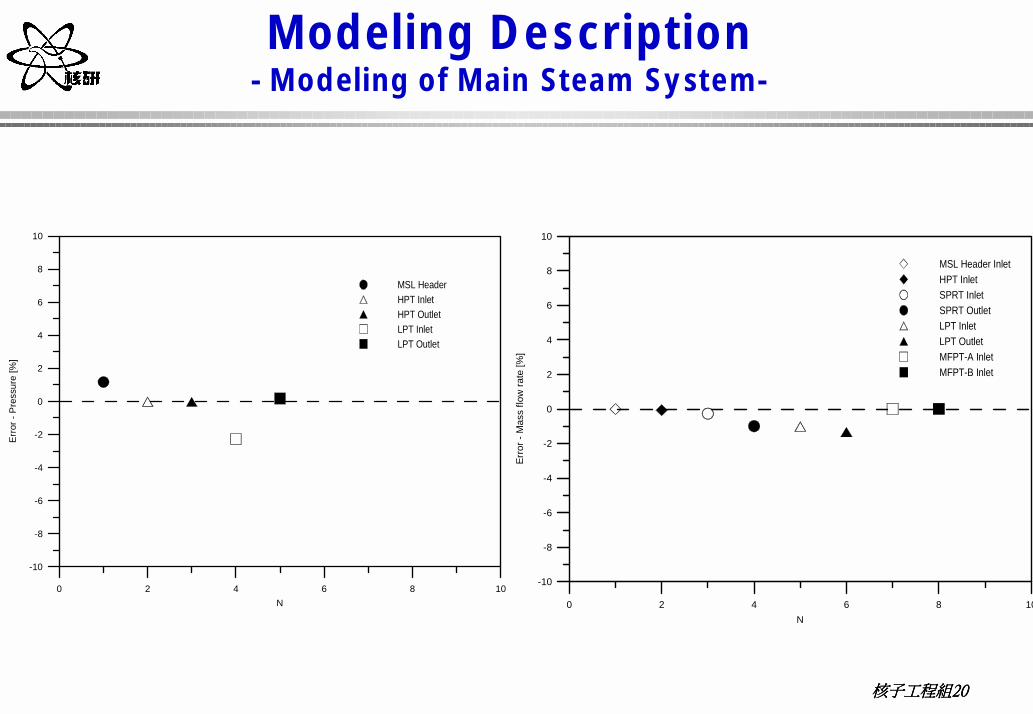
Modeling Description- Modeling of Main Steam System-
0 2 4 6 8 10N
-10
-8
-6
-4
-2
0
2
4
6
8
10
Erro
r - P
ress
ure
[%]
MSL HeaderHPT InletHPT OutletLPT InletLPT Outlet
0 2 4 6 8 10N
-10
-8
-6
-4
-2
0
2
4
6
8
10
Erro
r - M
ass
flow
rate
[%]
MSL Header InletHPT InletSPRT InletSPRT OutletLPT InletLPT OutletMFPT-A InletMFPT-B Inlet
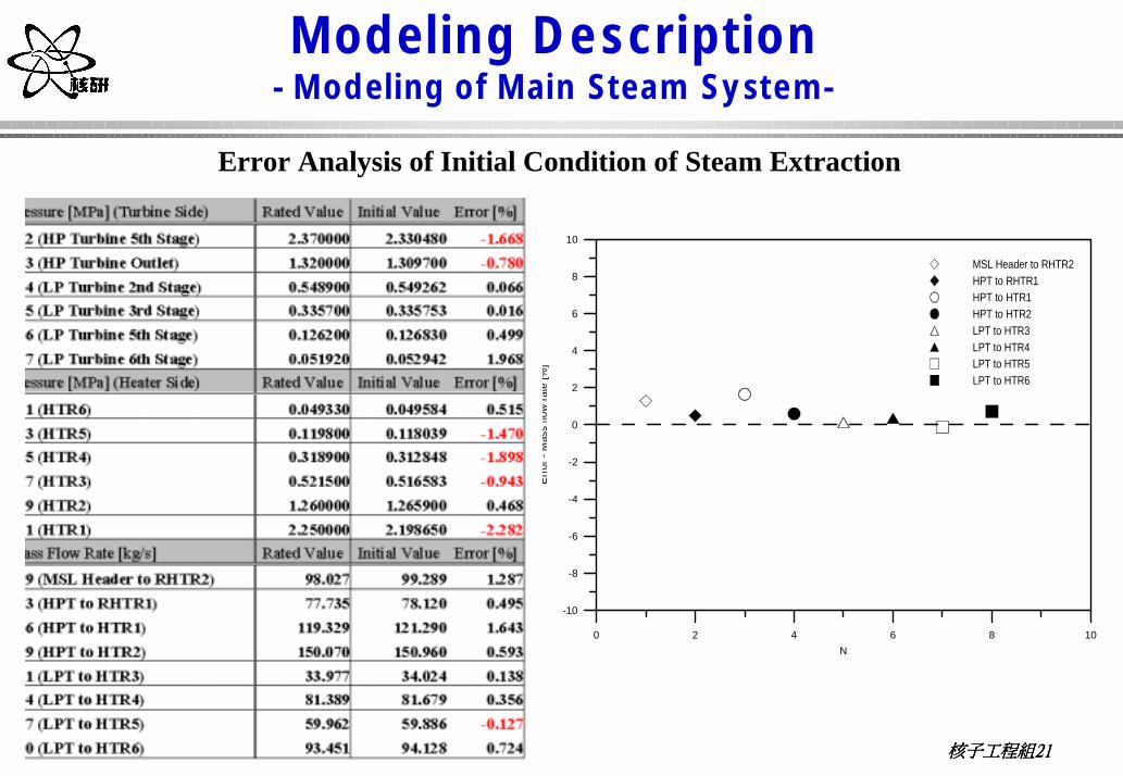
核子工程組核子工程組核子工程組核子工程組21212121
Modeling Description- Modeling of Main Steam System-
0 2 4 6 8 10N
-10
-8
-6
-4
-2
0
2
4
6
8
10
Erro
r - M
ass
flow
rate
[%]
MSL Header to RHTR2HPT to RHTR1HPT to HTR1HPT to HTR2LPT to HTR3LPT to HTR4LPT to HTR5LPT to HTR6
Error Analysis of Initial Condition of Steam Extraction

核子工程組核子工程組核子工程組核子工程組22222222
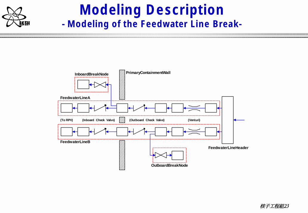
Modeling Description- Modeling of the Feedwater Line Break-
� Two separated FW lines entering the reactor vessel are simulated.
� On each line the venturi is also modeled using junction component with reduced flow area.
� To simulate the internal choking, the Moody critical flow model is applied on the break junction as well as theventuri junction.
核子工程組核子工程組核子工程組核子工程組23232323
Modeling Description- Modeling of the Feedwater Line Break-
(Outboard Check Valve)(To RPV) (Venturi)
Feedwater Line Header
Feedwater Line A
Feedwater Line B
Inboard Break Node
(Inboard Check Valve)
Outboard Break Node
Primary Containment Wall

核子工程組核子工程組核子工程組核子工程組24242424
Modeling Sensitivity Study
� To ensure proper or conservative modeling, sensitivity study of five important parameters are performed. Those parameters include� inertia of feedwater pumps
A range of pump inertia (100%, 75% and 50% of the design inertia of FWPT, 930.0 kg-m2 ) is studies.
� Moody critical flow modelThe quantitative effect of using Moody model is verified by comparison against the
build-in best estimate choked-flow model � size of nodding right before the break
The node right before the break is subdivided by three different kinds of nodding size in term of L/D (0.34, 0.71 and 1.06).
� discharge coefficient; and As required by the Appendix K, studies of the effect of discharge coefficient
ranged from 0.6 to 1.0 were performed. � internal choking on Venturi.
If internal choking occurs on the Venturi, the break flow might be limited by the area of Venturi.

核子工程組核子工程組核子工程組核子工程組25252525
General As sumptions for
Event Licensing Analysis
� Initial ConditionsParameter Initial Value
Reactor Thermal Power [MWt]4005
(102 %)
Steam and Feedwater Flow [kg/s] 2164.8(102 %)
Feedwater Temperature [°°°°C]216.9
(102 %)
Turbine Driven Feedwater Pump Speed [rpm](Pump Rated Speed: 4920 rpm) 4957
核子工程組核子工程組核子工程組核子工程組26262626
General As sumptions for
Event Licensing Analysis
� Plant Operations�The FW pumps go to maximum speed and corresponding flow
runs out (maximum controller demand) immediately upon event initiation;
�The FW pumps are continuously running along with the coast down of FW pump turbines;
�MSIV closure time for the inboard break is 5.5 seconds and 14.55seconds for the outboard break. Information is derived from pressure and steam flow boundaries supported by GE;
� Extraction steam continues to enter the FW heater and the FW pump turbines until steam inventory is depleted or blocked by the non-return valves designed to protect main turbines;
核子工程組核子工程組核子工程組核子工程組27272727
General As sumptions for
Event Licensing Analysis
� Plant Operations�Non-safety systems and components are assumed to
fail in ways that maximum the amount of water mass and energy blowdown;
�Condensate pumps and condensate booster pumps continue operating and provide flow to the FW system;
�Transfer of condensate storage tank inventory available to the condensate system is credited; and
�FW flow to the vessel through the unbroken line continues intermittently through the event, depending on the FW line and RPV pressures.

核子工程組核子工程組核子工程組核子工程組28282828
General As sumptions for
Event Licensing Analysis
� Modeling Assumptions�Homogeneous Moody model is applied to calculate
blowdown flow rate; �The effects of critical flow at various valves, fittings
and components are considered; �Flow losses (piping friction, local losses, and
elevation effects) is considered in determining the maximum break flow;
�The pump curves of flow run out are used to model the FWPs;
�Flashing of saturated water and the associated effect of flashing on steam supply are considered;

核子工程組核子工程組核子工程組核子工程組29292929
General As sumptions for
Event Licensing Analysis
�The effect of stored heat from metal and saturated water stored in FW heater shell sides on the FW heating are considered;
� Calculated extraction steam and drain water to the FW system is multiplied by a factor of 1.05;
� Calculated steam flow entering into the FW pump turbines is multiplied by a factor of 1.05;
�The L/D of nodes right before the break is set to be 0.34 by sensitivity analysis; and
� The discharge coefficient is conservatively set to be 1.0 by sensitivity analysis .

核子工程組核子工程組核子工程組核子工程組30303030
Results
Feedwater Pump Run out Speed
Extraction Steam Flow from H. P. Turbine
T o R P V
O R F
T D J
IS O V
665
6 5 1
6 7 36 7 5
H T R # 2H T R # 1
E x t ra c t io n f ro mH P T u r b in e # 5
D ra in f ro m M S RR H T R # 1 D ra in T a n k
D r a in f ro m M S RR H T R # 2 D r a in T a n k
V e n t f ro m M S RR H T R # 2 D ra in T a n k
V e n t f ro m M S RR H T R # 1 D ra in T a n k
663
E x t ra c t io n f ro m H PT u rb in e e x h a u s t
653
655
D r a in toH T R # 2
T D J
T D V
6 6 1
C V
D ra in toH T R # 3T D V
C V
657
659
667
669
T D J
T D V
D ra in fr o mH T R # 1
7 6 1
7 6 2
7 6 4
7 6 5
7 7 0
7 7 1
7 7 3
7 7 4
7 8 1
7 8 2
7 6 3
7 6 6
7 6 8
7 7 2
7 7 5
7 7 6
7 7 7
671
6 7 7
7 8 3
7 8 6 7 8 5 7 8 46 7 9

核子工程組核子工程組核子工程組核子工程組31313131
Results
Extraction Steam Flow from L. P. Turbine Steam Pressure before and after MSIV

核子工程組核子工程組核子工程組核子工程組32323232
Results
0 100 200 300 400 500 600 700Time [sec]
-1000
0
1000
2000
3000
4000
5000
Flow
[kg/
sec]
Break Flow
FW Flows of Both Intact and Broken Lines Blowdown Flow Rate
核子工程組核子工程組核子工程組核子工程組33333333
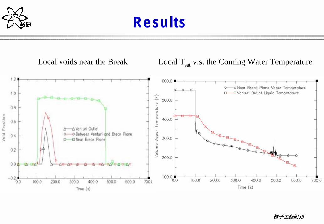
Results
Local voids near the Break Local Tsat v.s. the Coming Water Temperature

核子工程組核子工程組核子工程組核子工程組34343434
Results
0 100 200 300 400 500 600 700Time [sec]
-200000
0
200000
400000
600000
800000
1000000
1200000
Flow
Ent
halp
y [J
/kg]
Break Flow Enthalpy
Blowdown Enthalpy Feewater Heater Shell Side Pressures

核子工程組核子工程組核子工程組核子工程組35353535
Results
Feewater Heater Shell Side Temperatures Temperature Change across the L. P. Heater
核子工程組核子工程組核子工程組核子工程組36363636
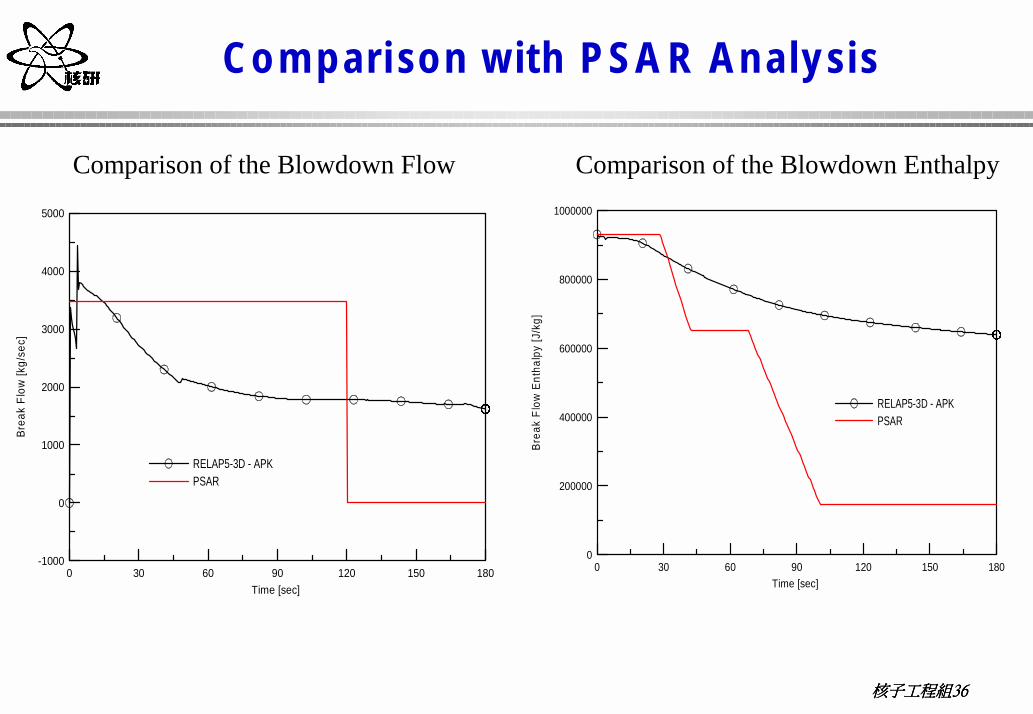
Comparison with PSA R Analysis
0 30 60 90 120 150 180Time [sec]
-1000
0
1000
2000
3000
4000
5000
Brea
k Fl
ow [k
g/se
c]
RELAP5-3D - APKPSAR
0 30 60 90 120 150 180Time [sec]
0
200000
400000
600000
800000
1000000
Brea
k Fl
ow E
ntha
lpy
[J/k
g]
RELAP5-3D - APKPSAR
Comparison of the Blowdown Flow Comparison of the Blowdown Enthalpy
核子工程組核子工程組核子工程組核子工程組37373737
Conclusions
� The blowdown of BOP system caused by the FW line break has been successfully analyzed by the Appendix K version of RELAP5-3D.
� The essential components of the BOP simulation scope include � steam header,� high pressure and low pressure turbines,� MSR,� FWP turbines,� main condenser,� condensate and booster pumps,� FW heaters of six stages,� steam extraction of seven stages,� turbine driven FW pumps.

核子工程組核子工程組核子工程組核子工程組38383838
Conclusions
� Important phenomena involved can be properly simulated by RELAP5-3D. Those phenomena are� critical flow at the break and the internal venturi, � flashing of FW near the break, � run out and coast down of the FW pumps, � steam extraction to FW heaters and FWP turbines, � flashing of saturated water initially stored inside the FW heater shell
sides and MSR drain tanks, � energy release from saturated water and system metal, and � cold water transportation from the main condenser to the break.
� The successful application of the RELAP5 for the FW blowdownanalysis indicates that the advanced RELAP5 code can extent it’s traditional reactor safety analysis to entire power conversion system simulation.

核子工程組核子工程組核子工程組核子工程組39393939
Conclusions
� Through comparisons against the PSAR curves for the inboard break, it was observed that� the blowdown flow rate are generally less than the constant value applied in
PSAR in the first 120 seconds; � After 120 seconds, the present analysis conservatively assumes continuous
operation of the condensate and booster pumps;� The accumulated blowdown inventory can be bounded by the PSAR only for
the first 180 seconds;� the blowdown enthalpy decreases more gradually as compared with the
PSAR; � It can be seen that accumulated blowdown energy from RELAP5-3D/K
calculation was bounded by the PSAR only in the early 120 seconds;� The revised blowdown flow and enthalpy using RELAP5-3D/K can provide a
new and solid basis for the FSAR containment analysis of the Lungmennuclear power plant.

核子工程組核子工程組核子工程組核子工程組40404040
Future WorkPhase II Integral Blowdown Analysis
HPCF
039069
041071
Act
ive
Cor
e C
hann
el
Byp
ass
Cha
nnel
RCIC
FW
3 RIPsw/o MG Set
3 RIPsw/ MG Set
070 040
096096-1
066
036
036-3036-2036-2
036-1034
032
033030 030
028 028
026 026
024 024
022022
020020
010 012014
004
002
FlowRestrictor
100
120
140
160
M SL_A
M SL_B
M SL_C
121
101
141
161
MS Nozzle
102
122
142
162
MS LineSection 1
SRV003A110
SRV004A111
SRV003B130
SRV004B131
SRV003C150
SRV004C151
SRV003D170
SRV004D171
103
123
143
163
MS LineSection 2
SRV005A112
SRV005D172
SRV006D173
SRV006A113
SRV007B134
SRV005B132
SRV006B133
SRV007C154
SRV005C152
SRV006C153
3 RIPsw/ MG Set
1 RIPsw/o MG Set
011
M SL_D
Nodding Diagram for RPV Blowdown

核子工程組核子工程組核子工程組核子工程組41414141
Future WorkEngineering Simulator of LungMen ABWR
SIMPORTRELAP5
Major System Dynamic Simulation
Simulation environment, contorl systems,secondary BOP & ESF, Man-machine Interface
Systems invlove:(1)Reactor System -RPV -3-D kientics -ADS(2)Power Conversion System
-main steam -main turbines -main condensor -main FW
Systems involve(1)control systems-FW control(FWC)-steam bypass & P control(SBPC)-recir. Flow control (RFCS)(2)ESF-reactor protection system(RPS)-high H core Flood (HPCF)-reactor core isolation cooling (RCIC)-residual heat removal (RHR)-standby boron liquid control (SBLC)(3)man-machine interface
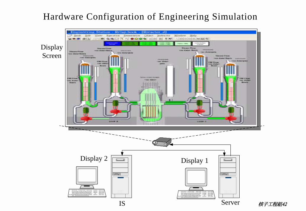
核子工程組核子工程組核子工程組核子工程組42424242IS Server
Display 1
DisplayScreen
Display 2
Hardware Configuration of Engineering Simulation