Embed Size (px)
Citation preview

Mould lubrication Session 18 1
Düsseldorf, 27 June – 1 July 2011
Modeling of Heat Transfer and Solidification Processes in Thin Slab Caster Authors Alexander Vakhrushev1, Andreas Ludwig1, 2, Menghuai Wu2, Yong Tang3, Gerald Nitzl4, Gernot Hackl3
1 Christian Doppler Laboratory for Multiphase Modeling of Metallurgical Processes, University of Leoben, A-8700 Leoben, Austria 2 Simulation and Modeling of Metallurgical Processes, Department of Metallurgy, University of Leoben, A-8700 Leoben, Austria 3 RHI AG, Technology Center, Standort Leoben, Magnesitstrasse 2, A-8700 Leoben, Austria 4 RHI AG, 1100 Vienna, Wienerberstrasse 11, Austria Contact information Dr. Alexander Vakhrushev Chair for Modeling and Simulation of Metallurgical Processes, Department of Metallurgy, University of Leoben Franz-Josef-Straße 18, A-8700 Leoben, Austria E-Mail: [email protected] Tel.: +43 3842 - 402 - 3125 Keywords Thin slab casting, numerical modeling, solidification, heat transfer, multiphase flow, turbulence Abstract Complex numerical model for the description of solidification processes in the thin slab caster is developed. The highly turbulent flow at the region of the submerged entry nozzle is simulated along with its influence on the solidification. Open source CFD software package OpenFOAM is used as the main simulation tool. The important aspects of the heat transfer modeling are considered, taking into account latent heat release and various cooling mechanisms. The interaction between two phase region and turbulent flow is modeled. Accuracy and reliability of different numerical schemes for the temperature field prediction are studied. Unfavorable influence of the artificial numerical heat sources is investigated, which occur due to high order discretization of the energy equation on the non-orthogonal grids. Numerical simulation of the processes in the thin slab caster is much more complicated task, if compared to the solidification in the traditional continuous caster. Thus, presented results of the studies, achieved with the designed model, have direct practical application and are of the great importance for the continuous casting industry and relevant application fields.
Introduction The numerical simulation of various physical processes is a key issue in the modern CFD research field. In certain specific cases, it is the unique tool that enables the investigated phenomena to be examined in detail. Solidification in the continuous casting devices is the instance of the corresponding complex process, combining the highly turbulent flow, which interacts with the two phase region called the mushy zone. All considered processes are followed by the phase transition, latent heat diffusion / absorption due to the phase change, etc. Industrial measurements in continuous casting can only produce information regarding the total mass flow rate of the liquid melt, casting speed, surface heat
flux extraction values, slag interface oscillations and similar available qualities. However, it is almost impossible to read process parameters from inside the mold due to the high temperatures and ferrostatic pressure during casting. On the one hand, physical experiments with water modeling facilitate an understanding of the hydrodynamics of the turbulent flow in the continuous caster. On the other hand, the phase transition and the influence of the mushy zone presence are not taken into account. Thereby, the numerical simulation using the CFD approach plays a rather important role in continuous casting modeling. The current work focuses on solidification modeling with an application for Thin slab continuous casting using OpenFOAM as the main programming tool.
Proceedings of Decision and Control, 44th IEEE Conference, 2005, P. 1503- 1508 [8] C. D. Cuntan; I. I. Baciu: Fuzzy Algorithm Used to Water Debit Control to the Secondary Cooling in Continuous Casting Proces; Analele Universitatii „Eftimie Murgu“, 2005, ISSN 1453-7394. P. 99-104 [9] Thomas, B. G. et al.: Online Dynamic Control of Cooling in Continuous Casting of Thin Steel Slabs; In Proceedings of 2006 NSF Design, Service, and Manufacturing Grantees and Research Conference, 2006, P. 11 [10] Zhenping Ji; Jian Yang: Online Dynamic Control of Secondary Cooling for the Continuous Casting Process; In Proceedings of Third International Conference on Intelligent Networks and Intelligent Systems,2010, P. 4 [11] Pyszko, R.; Příhoda, M.; Molínek, J.; Fojtík, P.: Numerical model for temperature field kinetics for round strands; In Proceedings of 1st International Conference STEELSIM, 2005, P. 11 [12] Pyszko, R. et al.: Advanced Process Monitoring Systems for Continuous Processes; In Proceedings of the 16th IFAC World Congress, Prague, Elsevier, 2006 [13] Kavička, F.; Štětina, J.; Sekanina, B; Stransky, K.; Dobrovska, J; Heger, J.: The optimization of a concasting technology by two numerical models; Journal of Materials Processing Technology. 185 (1-3)., 2007, ISSN 0924-0136. P. 152 - 159. [14] Mauder, T.; Kavička, F.; Štětina, J.; Franek, Z.; Masarik, M. A.: Mathematical & stochastic modelling of the concasting of steel slabs; SLABS. In Sborník konference. Tanger. Hradec nad Moravicí: Tanger Ltd., 2009, ISBN: 978-80-87294-10- 9, P. 41-48 [15] G. Hulkó.: Control of Distributed Parameter Systems by means of Multi-Input and Multi-Distributed - Output Systems; In: Preprints of 10-th World Congress of IFAC, 1987 [16] G. Hulkó, et al.: Modeling, Control and Design of Distributed Parameter Systems with Demonstrations in MATLAB. Publishing House of STU Bratislava, (1998) www.mathworks.com/support/books/ [17] G. Hulkó, et al.: Distributed Parameter Systems web portal, (2003-2008), www.dpscontrol.sk [18] G. Hulkó, et al.: Distributed Parameter Systems Blockset for MATLAB & Simulink. Third-Party MathWorks product. Natics – Bratislava, 2003-2008 www.mathworks.com/products/connections/ [19] G. Hulkó, et al.: Engineering Methods and Software Support for Modeling and Design of
Discrete-Time Control of Distributed Parameter Systems; The European Control Conference 2009 Budapest [20] G. Hulkó, et al.: Engineering Methods and Software Support for Modeling and Design of Discrete-Time Control of Distributed Parameter Systems, European Journal of Control. ISSN 0947-3580.Vol. 15, Iss. 3-4 ,2009, Fundamental Issues in Control, P. 407-417.

Mould lubrication Session 18 2
Düsseldorf, 27 June – 1 July 2011
A number of the developed numerical models to account for both fluid flow and heat transfer, incorporating the kinetics of the solidification [1-2] are know from the literature. Unfortunately, only the laminar behavior of the solidified liquid melt is included in most of the recent solidification models [3-6]. In the presented studies, the turbulence model considering multiphase media as a viscous mixture is used to simulate solidification in the steel continuous caster. The approaches for handling the turbulence during solidification reported in contributions [7-10] are used. Porous resistance of the two-phase region is combined with the heat transfer modeling, taking into account the influence of the turbulent flow [11-12]. The presented work includes the numerical model description along with a numerical simulation performed for the real 3D geometry of the TS continuous caster. Model description In presented study, the solidification process is considered along with a highly turbulent flow. There are a number of approaches for modeling solidification that are widely used in the modern CFD field [13]. Some of these use a fixed numerical grid and averaged physical properties of the solidified fluid, others consider front tracking between solid and liquid phases along with adaptive mesh refinement, etc. For the study currently presented, a fixed finite volume mesh is used with a so-called collocated or non-staggered variable arrangement (Rhie and Chow [14], Perić [15]), where all physical values share the same control volumes (CV), and all flux variables reside on the CV faces. The generalized form of the divergence theorem is used throughout the discretization procedure to represent mass, momentum and energy conservation laws in integral form over the control volume. Unsteady formulation is used to track time-dependent effects during solidification. Additional assumptions are used to model the investigated phenomena: the multiphase system is described as a viscous fluid with a mixture of properties [3-6], thus it is assumed that the integration control volume is large enough to incorporate a representative amount of the liquid and solid phase in order to mimic the mushy zone; the mixture continuum combines liquid -phase and solid s -phase (quantified by the corresponding volume fractions f and sf ), which changes continuously from a pure liquid region, through the
mushy zone (two phase region), to the complete solid region; the solidified shell along the mold walls morphologically represents the columnar phase (dendrites), which is moving with a constant pulling (casting) velocity su
. The amount of the solid phase is predefined with a solid fraction / temperature curve varying for different materials, which is described later. The Navier-Stokes equations with an assumption of the liquid incompressibility are used to simulate the melt motion. Only one set of equations is formulated for both phases in the Eulerian frame of the reference. The mixture velocity ssufufu
+= represents a weighted sum of the liquid and solid velocities with the phase fractions as weighting factors. Thereby, the equation system consisting of the continuity and momentum equations is
0=⋅∇ u , (1)
( ) moneff )( Supuutu
+⋅∇∇+−∇=⋅∇+∂∂ μρρ . (2)
It should be noted that the effective dynamic viscosity of the liquid effμ in the momentum equation (2) is variable throughout the calculation domain due to the turbulence effects. The multiphase behavior of the mixture is defined by the source tem monS
in the
same equation, which represents drag force inside the porous region, formed by dendrites. It is modeled based on the Blake-Kozeny law:
)( smon uuK
S −⋅−= μ , (3)
where μ represents laminar viscosity and )( suu
− is a relative velocity of the mixture in the porous region. The permeability K of the mushy zone depends on the quantity of the solid phase and the characteristic size of the dendrites, referred to by Gu and Beckermann as the primary arm spacing 1λ [16]:
21
42s
3
106)1( λ⋅⋅⋅−
= −
ffK s . (4)
To track the evolution of the solid phase, the prescribed relation between solid fraction, sf and
Mould lubrication Session 18 3
Düsseldorf, 27 June – 1 July 2011
temperature T of different types (e.g. lever rule, Gulliver-Scheil) is used. The complexity of the numerical modeling of the solidification processes the continuous casting arises mostly due to the transition from the completely turbulent flow to the motion of the solid body with the prescribed constant velocity. Thus, it is desirable to employ a comprehensive model, which incorporates turbulent core description along with a laminar sublayer and a “solid body” behavior for the limit case
1s =f . In the presented study, a RANS turbulence model is used based on a low Reynolds number
ε−k model, introduced by Prescott and Incropera [7-10]:
( ) ( ) kkt,
t
PrSGkku
tk +−+
∇
+⋅∇=⋅∇+
∂∂ ρεμμρρ
(5)
( ) ( )
,
Pr2
21
t,
t
εεε
ε
ερε
εμμερρε
Sk
Ck
GC
ut
+−+
+
∇
+⋅∇=⋅∇+
∂∂
(6)
kK
S ⋅−= μk , εμ
ε ⋅−=K
S , (7)
where 1Pr kt, = , and 3.1Prt, =ε are the turbulent
Prandtl numbers for k and ε respectively; G is the shear production of turbulence kinetic energy [7-10]. Equations (5-7) allow the turbulence during solidification to be handled, where turbulence parameters k and ε are dumped within porous region according to the formulation (7). The permeability of a coherent mushy zone is decreasing based on the relation (4) along with a growing solid fraction value. For the closure of the solidification model system, it is necessary to introduce the energy equation:
( ) eeff SThuth +∇⋅∇=⋅∇+
∂∂ λρρ . (8)
Equation (8) is applied to the entire domain, where h
is the sensitive enthalpy dTchhT
T+=ref
pref . In the
presented study, it is assumed that reference enthalpy refh and temperature refT are equal to zero,
and the specific heat pc is constant. Thus, sensitive
enthalpy can also be rewritten in the form of Tch p= .
It is known that a heat of fusion, also called latent heat, is released due to solidification or absorbed during melting for the phase transition from liquid to solid state or vice versa. The latent heat L is taken into account in the model by the use of an additional source term eS in the energy equation, which represents a combination of the heat release caused by phase change in the course of time and due to the amount advected with a melt
ssse fuLtfLS ∇⋅+∂∂= ρρ . (9)
From the formulation (2) of the momentum conservation and energy transports (8), the influence of turbulence is considered by the effective viscosity
teff μμμ += and the effective thermal
conductivity teff λλλ += . Turbulence values are calculated based on model parameters and coefficients: ερμ μ
2t kC= , ht,ptt Prcμλ = , 09,0=μC
is a model parameter, 85,0Pr ht, = is the turbulent
Prandtl number for the energy equation. Solution algorithm It is relatively clear that the model described poses a great challenge for numerical implementation, especially for complex 3D geometries. It contains a large amount of nonlinearity, and the question of coupling continuity, momentum, energy and the equations of the turbulent parameters transport arises. For the pressure-velocity coupling, a modified version of the PIMPLE algorithm, implemented in OpenFOAM, is used. The PIMPLE algorithm represents a merged version of the widely used SIMPLE and PISO methods for pressure-velocity coupling [17-18] for the large time-step transient calculations. Internal iteration loops are used, with underelaxations being applied either for the model variables or for the matrices of the linear equations to be solved. The iteration process stabilizes the numerical solution and enable the use of the time-step values, resulting in the Courant number 1>>Co . Other sources of nonlinearity emerge due to the relationship between the permeability of the mushy zone K and the solid fraction sf . Moreover, according to the formulations (2)-(4) and the energy equation (8), the solidification is strongly coupled with

Mould lubrication Session 18 4
Düsseldorf, 27 June – 1 July 2011
the melt motion due to convention / diffusion mechanisms of the heat transfer and latent heat release during the phase change. Here, a so-called temperature recovery method is used to couple fluid flow with the heat transfer and solidification [13]. For the solution of the coupled heat transfer problem a heat extraction rate is defined for the mold surface. The mold area is defined as the primary zone and further in the presented studies it is specified by setting extracted heat flux profiles, which can be measured during industrial processes and provided as external data for the application. The programmed implementation of the heat flux boundary condition accepts a general format of the user data (e.g. hyperbolic, polynomial interpolation, piecewise-linear profile, etc.). In order to apply heat flux BC, it is necessary to consider the heat balance at the wall-liquid interface:
wallfwall nddTq
≡ λ . (10)
The equation (10) for the predefined heat flux can vary depending on either the laminar or wall function approach being used to calculate wall temperature values [19]. Linear interpolation was used to reconstruct indeterminate heat flux values. The considered option is rather useful when several measured points are presented along the whole mold area, but there is a lack of intermediate data. For the presented study 3 different zones were considered for the wide face. The uniform heat flux is predefined for the narrow faces (see Tab. 1).
Figure 1: Outlet temperature values dependent on velocity direction
An additional boundary condition is applied for the outlet of the numerical domain. It is dependent on
velocity direction (Fig. 1) and is often used in CFD simulations. A boundary condition base on the velocity direction can be used to stabilize the solution (e.g. defining laminar backflow). A flow chart of the solidification solver is presented as a generalization of the described algorithm (Fig. 2). It should be noted that all internal loops of the solution algorithm are executed until either the global convergence criterion is fulfilled (for a fully transient solution) or the prescribed number of steps is executed (e. g. if a steady state is the aim).
Figure 2: Flow chart of the solidification solver
Finite volume method is used for the discretization of the primary PDE system (1-9) describing the heat and mass transfer in the solidifying melt with a general unstructured grid being used (Fig. 3).
Figure 3: Domain decomposition for the parallel calculations (metis method, 4 CPUs)
Previous studies are used to verify the implementation of the solidification model using OpenFOAM Finite Volume Method libraries [11-12, 20-22]. First of all, the designed solidification model results for the 2D case were compared with the benchmark, carried out with the FLUENT

Mould lubrication Session 18 5
Düsseldorf, 27 June – 1 July 2011
software. The detailed setup and the results of the reference case is presented in [12, 22]. Preliminary studies Based on the results of the previous studies [12, 22] a preliminary numerical solution for the TS caster geometry was obtained using the relevant solidification model designed and approved formerly for the modeling of a convectional caster. The schematic setup of a continuous caster simulation is presented in Fig. 4. The considered calculation domain includes the region of the SEN being immersed into the mold of the TS type; top of the SEN is defined as the velocity inlet (a flow rate of the liquid melt is fixed) and the bottom of the mold represents the pressure outlet to identify the boundary conditions for the calculation of the steel melt motion. Additionally, inlet parameters of the flow predetermine the turbulence level being introduced into the simulation domain.
Figure 4: Scheme of the solution domain for the TS caster simulation
To complete a formulation of the boundary value problem for the primary PDE system (1)-(9), a no-slip boundary condition is defined for the mold walls by fixing a constant casting velocity at the firm surfaces. Top surface of the mold, representing a slag, is an adiabatic stationary wall with the slippage condition for the velocity field (normal component equals a zero value, for the tangential components a zero-gradient condition is applied). A given heat flux profile for the wide face of the mold is used to define a heat extraction at the primary
cooling zone (Tab. 1). Average heat flux over the narrow face is fixed and equals a constant value 1.65 MW/m2.
Table 1: Heat flux (wide face) (MW/m2) [23]
x-position from centerline of wide face
Depth below meniscus (m)
(a) 0.1 m (b) 0.2 m (c) 0.3 m
0 4.75 5 4.48 0.045 4.36 4.57 4.18 0.147 3.64 3.4 3.58 0.309 3.0 3.45 3.18 0.471 1.83 1.91 1.93 0.668 1.72 1.89 2 0.957 1.78 1.88 1.9
Inlet mass flow rate is 0.46 m/s, casting speed is 0.07 m/s. A numerical grid, previously used for the flow simulation, contains ~642·103 cells (Fig. 5).
Figure 5: Unstructured numerical grid details (initial decomposition, 642651 cells)
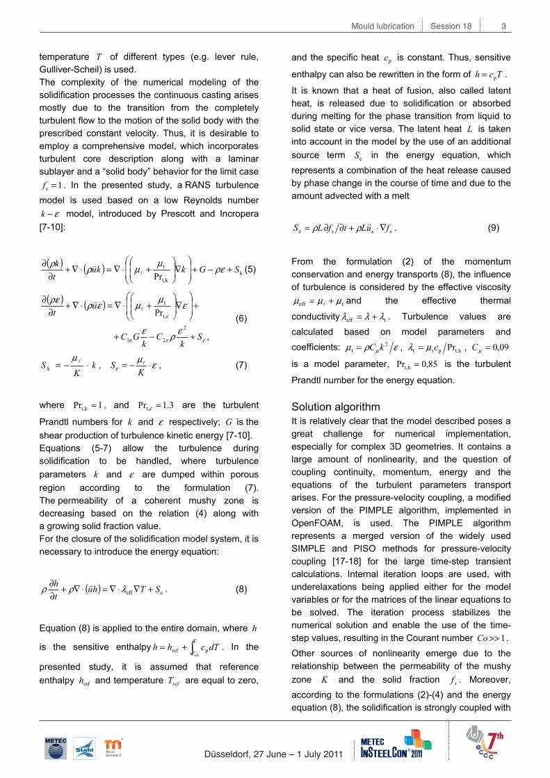
Using programmed OpenFOAM solidification solver, the process of the solid shell growth was modeled (Fig. 6). It was observed, that a large gap in the simulated shell is formed in the funnel widening of the casting mold. Valuation of the temperature filed in the simulated domain showed, that its maximum value exceeds pouring (tundish) temperature of the liquid melt for more then 100 K, which occurs totally unphysical according to the solidification theory, and moreover causes a violation of the energy conservation law. Thereupon that obtained result was accepted to be incorrect, additional analysis of the error sources were carried out to fix and improve the model being used.
Mould lubrication Session 18 6
Düsseldorf, 27 June – 1 July 2011
Figure 6: Preliminary result for the solid shell formation in the TS caster
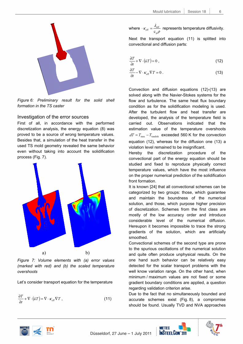
Investigation of the error sources First of all, in accordance with the performed discretization analysis, the energy equation (8) was proved to be a source of wrong temperature values. Besides that, a simulation of the heat transfer in the used TS mold geometry revealed the same behavior even without taking into account the solidification process (Fig. 7).
a) b)
Figure 7: Volume elements with (a) error values (marked with red) and (b) the scaled temperature overshoots
Let’s consider transport equation for the temperature
( ) TTutT ∇⋅∇=⋅∇+
∂∂
effκ , (11)
where ρ
λκp
effeff c
=⋅ represents temperature diffusivity.
Next the transport equation (11) is splitted into convectional and diffusion parts:
( ) 0=⋅∇+∂∂ TutT , (12)
0eff =∇⋅∇−∂∂ TtT κ . (13)
Convection and diffusion equations (12)-(13) are solved along with the Navier-Stokes systems for the flow and turbulence. The same heat flux boundary condition as for the solidification modeling is used. After the turbulent flow and heat transfer are developed, the analysis of the temperature field is carried out. Observations indicated that the estimation value of the temperature overshoots
tundishmax TTdT −= exceeded 560 K for the convection equation (12), whereas for the diffusion one (13) a violation level remained to be insignificant. Hereby the discretization procedure of the convectional part of the energy equation should be studied and fixed to reproduce physically correct temperature values, which have the most influence on the proper numerical prediction of the solidification front formation. It is known [24] that all convectional schemes can be categorized by two groups: those, which guarantee and maintain the boundness of the numerical solution, and those, which purpose higher precision of discretization. Schemes from the first class are mostly of the low accuracy order and introduce considerable level of the numerical diffusion. Hereupon it becomes impossible to trace the strong gradients of the solution, which are artificially smoothed. Convectional schemes of the second type are prone to the spurious oscillations of the numerical solution and quite often produce unphysical results. On the one hand such behavior can be relatively easy detected for the scalar transport problems with the well know variation range. On the other hand, when minimum / maximum values are not fixed or some gradient boundary conditions are applied, a question regarding validation criterion arise. Due to the fact that no simultaneously bounded and accurate schemes exist (Fig. 8), a compromise should be found. Usually TVD and NVA approaches

Mould lubrication Session 18 7
Düsseldorf, 27 June – 1 July 2011
are used to combine stability, boundness and accuracy for the discretization procedure.
Figure 8: Classification of the convectional schemes
To verify the numerical behavior of the convectional schemes implemented in the OpenFOAM CFD software a stationary transport equation was solved:
( ) 0=⋅∇ uφ , (14)
where φ is a passive scalar. A simulation domain for the convectional schemes benchmark represents a 2D square area (Fig. 9). Left and bottom sides correspond to the inlet, right and top are the outlet boundaries. Step profile of the scalar φ brought by the flow from the left is defined as
≤≤
<≤=
.161for1
,610for0
x
xφ , (15)
Right and the left boundaries are set to the zero gradient condition.
Figure 9: Initial setup for the convectional schemes test [24]
To simplify the interpretation of the test results velocity represents a unit vector with the fixed mesh-
to-flow angle 30=ϑ . Numerical grid is uniformly spaced and consists of the 30×30 control volumes. Comparison between the analytical and the numerical solutions of the transport equation (14) is made across the line which is 20 CV downstream from the left inlet boundary. The exact solution in this case is
≤≤+
+<≤=
=
.13634for1
,36340for0
32
y
y
xφ (16)
As provided by the analytical solution, the transported step profile should remain sharp. Hereby, the behavior of the numerical schemes is evaluated according to following criteria: diffusivity of the scheme (how the sudden change of the solution is smeared due to the lack of discretization accuracy) and the ability of the scheme to keep the physical boundaries of the transported scalar. According to advanced application practice the upwind differencing (UD), central differencing (CD), linear-upwind differencing (LUD [25]), self-filtered central differencing (SFCD [26]) and the Gamma [24] schemes were tested and compared. Figures, representing the test results, contain the colored map (left) of the simulated scalar transport along with the comparison plot of the exact and modeled profiles at the position 20 CVs downstream from the left boundary (top-right) and the numerical error distribution pattern (bottom-right).
Figure 10: Simulation results of a passive scalar transport (UD scheme)
During the studies it was obtained, that the upwind differencing provides the most bounded solution among considered convectional schemes without any

Mould lubrication Session 18 8
Düsseldorf, 27 June – 1 July 2011
additional numerical tricks due to its physical nature, resulting in the strongly smoothed step profile though (Fig. 10). Thus UD scheme is to diffusive and, despite it conserves scalar being transported within desired range, it can not tackle the strong gradient (which occur rather often during solidification processes). UD can be widely used for the starting period of the simulation procedure to stabilize it.
Figure 11: Simulation results of a passive scalar transport (CD scheme)
Central differencing is more accurate and follows the sudden change of the simulated value (see Fig. 11). However it produces spurious oscillations of the numerical solution up- and downstream. Thus a positive scalar can reach negative values as well as overshoots of the solution are obsereved. Linear upwind differencing (LUD) scheme is designed to take advantages of both UD and CD. It combines the boundness of the former and brings the accuracy of the latter. However according to the test results it still produces small under- and overshoots of the solution (see Fig. 12).
Figure 12: Simulation results of a passive scalar transport (LUD scheme)
To exclude the unboundedness of the numerical solution, a cell / face limiting of the gradient is applied
either between the neighboring volumes or at the interface between them. Such procedure is aimed to avoid unphysical peaks of the calculated gradients between the cells.
Figure 13: Simulation results of a passive scalar transport (LUD scheme with cell limiting)
After cell / face correction is applied one can observe that LUD scheme tracks both the sharpness of the step profile and the boundness of the simulated value (Fig. 13). The similar tests were carried out for the SFCD and the Gamma schemes. One can see the results (Fig. 14 and Fig. 15) with cell limiting been applied. As opposed to LUD scheme both of them lead to some overshoots ~1% of the maximum value at the step profile and seem to be a little bit more diffusive than LUD one.
Figure 14: Simulation results of a passive scalar transport (SFCD scheme with cell limiting)
According to the carried studies linear-upwind differencing scheme was selected to use for the convectional terms discretization as well as the introduction of the cell limiting of the gradients was applied. Both supplements of the initial algorithm roved to be effective to maintain the boundness of the solution.

Mould lubrication Session 18 9
Düsseldorf, 27 June – 1 July 2011
Figure 15: Simulation results of a passive scalar transport (Gamma scheme with cell limiting)
Additional mesh refinement was performed especially along the mold narrow and wide faces where the most solidification occurs (Fig. 16). Also some tetrahedral elements were transformed to the better-typed hexahedral ones which are known to provide better convergence and stability of the numerical solution.
Figure 16: Unstructured numerical grid (refined for the solidification modeling, 1611151 cells)
Simulation results of 3D Thin slab continuous caster Using the previously described model, the simulation of real continuous caster was carried out taking into account modifications of the numerical implementation. Pulling velocities were calculated as referred to [19] to tackle the curved surface of the funnel shape mold part
0s2 =∇ u . (17)
During numerical simulation the solid shell formation the proper shape was obtained (Fig. 17). Additional parameters of the melt flow were analyzed (Fig. 18).
Figure 17: Formation of the solid shell in the TS caster simulated with the improved model
a) b)
Figure 18: Distribution of (a) the temperature (left) and the solid fraction (right); (b) velocity magnitude (left) and the liquid pool boundary (right)
Generally the solid shell is formed along the wide and narrow walls, but due to the reduced thickness of the TS mold the mushy zone can coalesce while growing from the wide face of the chill. This mechanism is strongly influenced by the permeability parameter, which is hard to obtain from the measurements. If compared to the convectional caster the solidification in the thin slab CC courses much faster and the proper flow pattern is much more significant for such process. Conclusions Solidification modeling is of great importance for a wide range of fundamental and practical application fields. It helps the investigation of core processes for which industrial measurement methods are inadequate. The current study represents the
Mould lubrication Session 18 10
Düsseldorf, 27 June – 1 July 2011
implementation of the previously developed solidification model for the numerical simulation of continuous casting process in the thin slab continuous caster. Specifics of the heat transfer modeling are considered. It was found that some high order convectional schemes can produce unphysical results. A number of schemes are tested and the required corrections for the discretization procedure are made. Calculation of the casting velocities are carried out to tackle the complex shape of the funnel type parts of the TS mold. Final simulation results are presented and analyzed. References [1] Rappaz, M.: Modelling of Microstructure Formation in Solidification Processes; Int. Mater. Rev., 1989, vol. 34, Issue 3, P. 93-123 [2] Beckermann, C.; Viskanta, R.: Mathematical modeling of transport phenomena during alloy solidification; Appl. Mech. Rev., 1993, vol. 46, P. 1-27 [3] Voller, V. R.; Prakash, C.: A fixed grid numerical modeling methodology for convection-diffusion mushy region phase-change problems; Int. J. Heat Mass Transfer, 1987, vol. 30, No. 8, P. 1709-1719 [4] Voller, V. R.; et al.: The modeling of heat, mass and solute transport in solidification systems; Int. J. Heat Mass Transfer, 1989, 32 (9), P. 1719-1731 [5] Voller, V. R.; Brent, A. D.; Prakash, C.: Modeling the mushy region in a binary alloy; Appl. Math. Modeling, 1990, vol. 14, P. 320-326 [6] Voller, V. R.; Swaminathan, C. R.: General source-based method for solidification phase change; Num. Heat Trans., 1991, Part B, vol. 19, P. 175-189 [7] Prescott, P. J.; Incropera, F. P.: The effect of turbulence on solidification of a binary metal alloy with electromagnetic stirring; Transport Phenomena in Materials Processing and Manufacturing, ASME HTD, 1994, vol. 280, P. 59-69 [8] Prescott, P. J.; Incropera, F. P.: Convective transport phenomena and macrosegregation during solidification of a binary metal alloy: I-Numerical predictions; J. Heat Transfer, 1994 (116), P. 735-741 [9] Prescott, P. J.; Incropera, F. P.; Gaskell, D. R.: Convective transport phenomena and macrosegregation during solidification of a binary metal alloy: II-Experiments and comparisons with numerical predictions; Trans. ASME, 1994, vol. 116, P. 742-749 [10] Prescott, P. J.; Incropera, F. P.: The effect of turbulence on solidification of a binary metal alloy with electromagnetic stirring; Trans. ASME, 1995, vol. 117, P. 716-724
[11] Pfeiler, C.: Modeling of turbulent particle/gas dispersion in the mold region and particle entrapment into the solid shell of a steel continuous caster; PhD thesis, Montanuniversität Leoben, 2008 [12] Wu, M.; Vakhrushev, A.;; et al.: Importance of melt flow in solidifying mushy zone; Open Transport Phenomena J., 2010, vol. 2, P. 16-23 [13] Dantzig, J. A.; Rappaz, M.: Solidification; EPFL Press, 2009, 1 ed. [14] Rhie, C. M.; Chow, W. L.: A numerical study of the turbulent flow past an isolated airfoil with trailing edge separation; 3rd Joint Thermophysics, Fluids, Plasma and Heat Transfer Conference, St. Louis, Missouri, 1982 [15] Perić, M.: A Finite Volume method for the prediction of three-dimensional fluid flow in complex ducts; PhD thesis, Imperial College, University of London, 1985 [16] Gu, J. P.; Beckermann, C.: Simulation of convection and macrosegregation in a large steel ingot; Metall. Mater. Trans. A, 1999, vol. 33A, P.1357-1366 [17] Patankar, S. V.: Numerical Heat Transfer and Fluid Flow; Taylor & Francis, USA, 1980 [18] Ferziger, J. H.; Peric, M.: Computational Methods for Fluid Dynamics; Springer, 2002 [19] Fluent: User's Guide v6.3, Fluent Inc., 2006 [20] Pfeiler, C.; Thomas, B. G.; et al..: Solidification and particle entrapment during continuous casting steel; Steel Res. Int., 2008, vol. 79, P. 599-607 [21] Wu, M.; Ludwig, A.; Pfeiler, C.; Mayer, F.: Multiphase flow modelling and its application potentials in steel continuous casting; J. of Iron & Steel Res. Int., 2008, vol. 15 Supplement 1, P. 30-37 [22] Vakhrushev, A.; Ludwig, A.; Wu, M.; Tang, Y.; Nitzl, G.; Hackl, G.: Modeling of Turbulent Melt Flow and Solidification Processes in Steel Continuous Caster with the Open Source Software Package OpenFOAM; OSCIC’10 Conf., Munich [23] J.e. Camporredondo S.; at al.: Analysis of Thin-Slab casting by the Compact-Strip Process: Part I. Heat Extraction and Solidification; Metallurgical and Materials Transaction B, 2004, vol. 35B, P. 541-560 [24] Jasak, H.; Weller, H.G.; Gosman, A.D.: High resolution NVD differencing scheme for arbitrarily unstructured meshes; Int. J. Num. Methods in Fluids, 1999, vol. 31, P. 431-449 [25] Warming, R.F.; et al.: Upwind second-order difference schemes and applications in aerodynamic flows; AIAA J., 1976 (14), P. 1241–1249 [26] STAR-CD Manuals v2.1; Comp. Dynamics, 1991