Embed Size (px)
Citation preview
Hindawi Publishing CorporationInternational Journal of Aerospace EngineeringVolume 2008, Article ID 294681, 10 pagesdoi:10.1155/2008/294681
Research ArticleModeling of Moisture Diffusion in Carbon Braided Composites
S. Laurenzi, T. Albrizio, and M. Marchetti
Department of Aerospace and Astronautic Engineering, School of Aerospace Engineering, University of Rome La Sapienza,Via Eudossiana 18, Roma 00184, Italy
Correspondence should be addressed to M. Marchetti, [email protected]
Received 3 February 2007; Revised 8 May 2007; Accepted 17 September 2007
Recommended by Shuguang Li
In this study, we develop a methodology based on finite element analysis to predict the weight gain of carbon braided compositematerials exposed to moisture. The analysis was based on the analogy between thermal conduction and diffusion processes, whichallowed for a commercial code for finite element analysis to be used. A detailed finite element model using a repetitive unit cell(RUC) was developed both for bundle and carbon braided composites. Conditioning tests were performed to estimate the diffu-sivity of both the resin and composite. When comparing numerical and experimental results, it was observed that the procedureintroduces an average error of 20% and a maximum error of 31% if the RUC is assumed to be isotropic. On the other hand, theaverage error does not exceed 10% and the maximum error is less than 20% when the material is considered as orthotropic. Theprocedure is independent of the particular fiber architecture and can be extended to other composites.
Copyright © 2008 S. Laurenzi et al. This is an open access article distributed under the Creative Commons Attribution License,which permits unrestricted use, distribution, and reproduction in any medium, provided the original work is properly cited.
1. INTRODUCTION
Moisture absorption is a critical factor in the design of poly-mer composite materials applied to aerospace structure, asit affects the dimensional stability of the pieces in long andshort times.
Even small quantities of moisture absorbed from theenvironment can modify significantly the mechanical andphysical properties of composite materials [1–4]. Moistureproduces swelling, reduces the glass transition temperatureof the matrix, and affects matrix-dominated properties suchas interlaminar shear strength, toughness to fracture, impactresistance, and possibly debonding [1]. Other properties re-lated to the life cycle of the structure, such as resistance tofatigue, are affected as well: the fatigue behavior of any com-posite is influenced by the toughness of the resin and its re-sistance to microcracking.
The degradation of mechanical properties of compositesis strictly correlated with the weight change due to moistureabsorption. Previous studies show that the weight changeand the amount of moisture at equilibrium depend on theenvironmental conditions and the fiber architecture. Bao andYee investigated temperature effects on the moisture absorp-tion process for a BMI resin and its composites [4]. Experi-mental results verified that an increment of temperature cor-
responds to an acceleration of the diffusion process and toa decrease of the maximum amount of moisture at equilib-rium. The authors determined the diffusivity by measuringthe weight variation as a function of time at different temper-atures, and found that the activation energy for the reactiondepends on the resin, whereas the initial diffusivity dependsstrongly on the presence of the fibers. Some authors highlighta previously neglected problem, which is the dependence ofthe diffusivity on the humidity concentration in the material[5]. Experimental results show that the rate of absorption isfaster during the initial transition and then it tends to slowdown as it approaches equilibrium. This behavior is justifiedby the authors with the presence of voids and fractures cre-ated during the curing process. During the final stage, theincrease of the humidity content in the composite inducesswelling which causes the closure of such spaces and there-fore a decrease in diffusivity.
Zhou and Lucas [6] conditioned a unidirectional graph-ite/epoxy composite by immersing it in distilled water at var-ious temperatures. They found that the difference betweentheoretical and experimental results increases with the tem-perature of conditioning. The authors individuated the limittemperatures, and concluded that if T/Tg ≤ 0.25, the absorp-tion process follows Fick’s law; if T/Tg ≥ 0.5, the anomaliesare present in the mechanisms of diffusion. Similar results
2 International Journal of Aerospace Engineering
were obtained from Wan et al. for a three-axial braided com-posite [7]. The complex fiber architecture and the presenceof voids inside the composite justify the divergence betweenFick’s law and the experimental data. The authors also inves-tigated the effects of external loads on absorption and diffu-sion processes. The preloaded material showed an accelera-tion of the initial diffusion process with respect to unloadedmaterial and a subsequent reduction of the mechanical per-formances. On the other hand, an external load applied tothe material reduces the absorption process and improvesthe mechanical performance. Initially, the external load pro-duces an increment of microcracks with an enhancement ofdiffusivity; then the load induces plasticity that blocks themicrocracks reducing the rate of absorption.
Conditioning testing has been a useful way to understandthe mechanism of moisture diffusion and the effects on com-posite behavior and it is still the popular technique for de-signing composites. However, testing can require months ofexperiments with obvious costs. Prediction models for com-posite moisture diffusion and long term behavior would bepowerful tools for the designer. In the past, some effortshave been made to develop numerical and analytical meth-ods to predict degradation properties and moisture absorp-tion. These studies give an acceptable prediction of the finalmoisture content and the swelling coefficient for unidirec-tional fiber composites [3]. However, it is difficult to buildeffective methods for complex fiber architecture, due to theintrinsic nature of dual-scale phenomenon. Kondo and Takiand Lundgren and Gudmundson focus their attention on theanalogy and the importance of the fiber distribution in thecomposite [8, 9]. Tang et al. investigated the effects of the towmicrostructure on the moisture diffusion for woven compos-ites and determined the cross-sectional diffusivity of a singlebundle adopting a 3D unidirectional composite model withrandom fiber distribution [10].
Vaddadi et al. developed a methodology based on inverseanalysis techniques in order to estimate the parameters ofmoisture diffusion processes for unidirectional carbon rein-forcements [11, 12]. Both diffusion coefficient and humiditycontent at equilibrium were determined using few and sim-ple measurements of weight gain. This method used a cyclicprediction process based on the Kalman filter theory, whichis particularly effective in determining variables under non-linear conditions. The authors adopted the repetitive unit cellmodel for determining composite properties in equilibriumconditions, but this analysis cannot be extended to the tran-sitory period because the material cannot be analyzed uni-formly.
Here, we propose a numerical method based on finiteelement analysis to predict the weight gain as a function ofthe exposure time to moisture for composites with complexfiber architecture such as a carbon braid. The analogy be-tween Fourier’s and Fick’s laws has been adopted to use anavailable commercial code, Femap 8-Maya TMG, which im-plements the finite element analysis. To account for the mois-ture absorption in a composite as a dual-scale phenomenon,bundle- and carbon-braided RUCs were used for the finiteelement analysis. Conditioning tests were performed to vali-date the numerical model. Future work will determine stress
and strain produced in the composite by the moisture con-centration field assessed using this model.
2. THEORY
For most composites, such as carbon-glass/epoxy-polyester,it is assumed that the fibers are impermeable and that mois-ture diffuses only in the matrix. This hypothesis is not validfor composites with aramid fibers, which can absorb signifi-cant amount of moisture.
Considering that the matrix is homogeneous andisotropic, the moisture mass diffusion through the compos-ite material can be described using Fick’s law (equation (1)).The adoption of Fick’s law implies that the composite doesnot have any defects, as voids and microcracks.
Fick’s law (equation (1)) [2, 3, 13] is the equivalent ofFourier’s law (equation (2)) [13] for thermal diffusion, so it ispossible to use this analogy to study the diffusion of moisturethrough a material
∂C
∂t= D·
(∂2C
∂x2+∂2C
∂y2+∂2C
∂z2
), (1)
∂T
∂t= k
ρ·c ·(∂2T
∂x2+∂2T
∂y2+∂2T
∂z2
). (2)
The concentration C in (1) is equivalent to the temper-ature T in (2), whereas the diffusivity D is equivalent to thethermal diffusivity α = k/ρ·c. However, the correspondencebetween the boundary conditions is not so straightforward.The major problem is the discontinuity at the interface be-tween fiber and matrix. In fact, while the contact temperaturebetween two materials can be assumed to be the same, thisis not the case for moisture diffusion. Kondo and Taki andLundgren and Gudmundson [8, 9] proposed to introduce therelative concentration r, which represents the ratio betweenmoisture amount at the instant t and the moisture amountat equilibrium. This parameter can be considered approxi-mately continuous through the interface and can be used toset the boundary condition. The other boundary conditioncan be obtained from the flux, which is constant through theinterface for both thermal and diffusion processes. The mois-ture diffusion inside the material is slower than the heat flowby many orders of magnitude.
The analogy above is used to describe two different lev-els of moisture flow: inside the tow and through the tow,that is, in the microscale and in the mesoscale. Indeed, thetextile structure is made of fiber tows that are braided to-gether to define the macrostructure of the composite. Thefiber tows are formed by bundles of well-aligned fibers, yetsignificant empty volume is present in a tow. The arrange-ment within the bundles represents the microstructure of thematerial. We assumed that the empty space is completely re-placed by the matrix, and that the adhesion between fiberand matrix is perfect. Therefore, moisture diffuses throughthe macrostructure and through the space among the fibertows.
S. Laurenzi et al. 3
(a) (b)
(c) (d)
(e) (f)
(g)
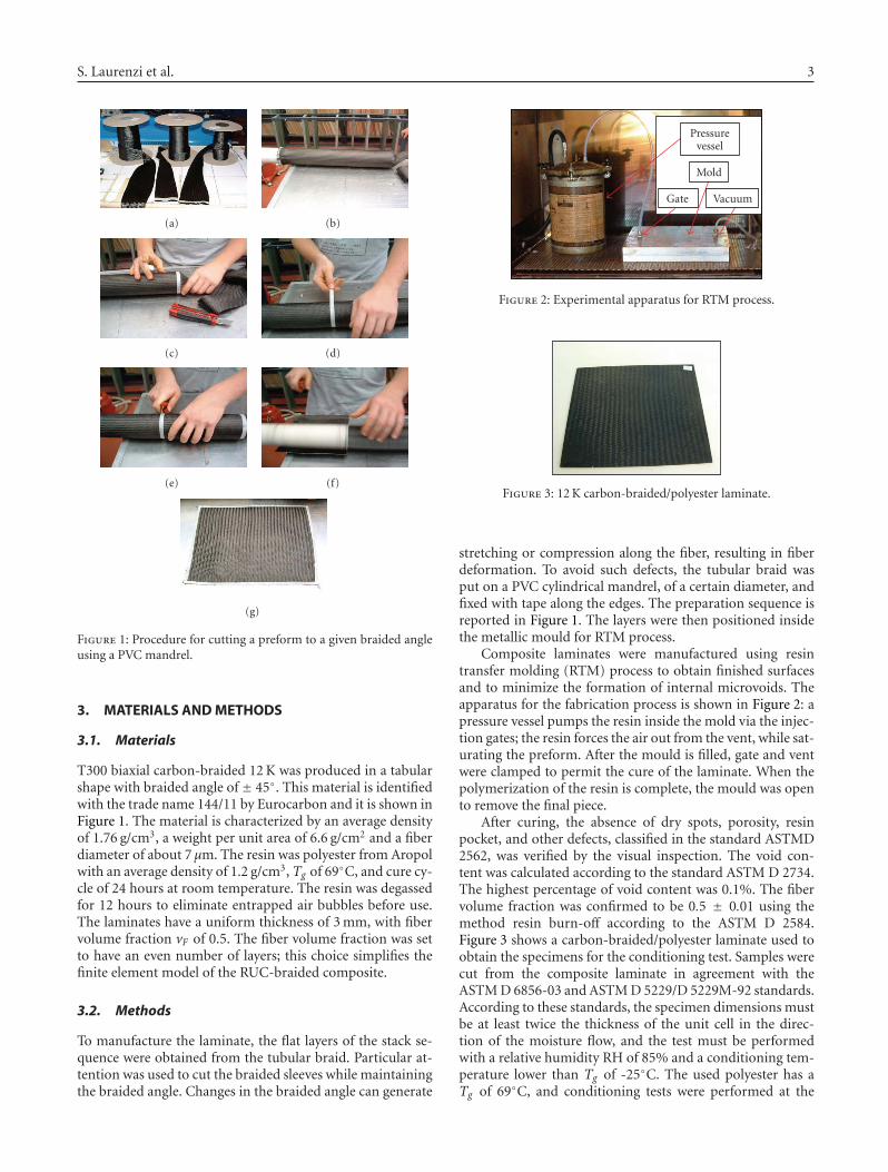
Figure 1: Procedure for cutting a preform to a given braided angleusing a PVC mandrel.
3. MATERIALS AND METHODS
3.1. Materials
T300 biaxial carbon-braided 12 K was produced in a tabularshape with braided angle of ± 45◦. This material is identifiedwith the trade name 144/11 by Eurocarbon and it is shown inFigure 1. The material is characterized by an average densityof 1.76 g/cm3, a weight per unit area of 6.6 g/cm2 and a fiberdiameter of about 7 μm. The resin was polyester from Aropolwith an average density of 1.2 g/cm3, Tg of 69◦C, and cure cy-cle of 24 hours at room temperature. The resin was degassedfor 12 hours to eliminate entrapped air bubbles before use.The laminates have a uniform thickness of 3 mm, with fibervolume fraction vF of 0.5. The fiber volume fraction was setto have an even number of layers; this choice simplifies thefinite element model of the RUC-braided composite.
3.2. Methods
To manufacture the laminate, the flat layers of the stack se-quence were obtained from the tubular braid. Particular at-tention was used to cut the braided sleeves while maintainingthe braided angle. Changes in the braided angle can generate
Pressurevessel
Mold
Gate Vacuum
Figure 2: Experimental apparatus for RTM process.
Figure 3: 12 K carbon-braided/polyester laminate.
stretching or compression along the fiber, resulting in fiberdeformation. To avoid such defects, the tubular braid wasput on a PVC cylindrical mandrel, of a certain diameter, andfixed with tape along the edges. The preparation sequence isreported in Figure 1. The layers were then positioned insidethe metallic mould for RTM process.
Composite laminates were manufactured using resintransfer molding (RTM) process to obtain finished surfacesand to minimize the formation of internal microvoids. Theapparatus for the fabrication process is shown in Figure 2: apressure vessel pumps the resin inside the mold via the injec-tion gates; the resin forces the air out from the vent, while sat-urating the preform. After the mould is filled, gate and ventwere clamped to permit the cure of the laminate. When thepolymerization of the resin is complete, the mould was opento remove the final piece.
After curing, the absence of dry spots, porosity, resinpocket, and other defects, classified in the standard ASTMD2562, was verified by the visual inspection. The void con-tent was calculated according to the standard ASTM D 2734.The highest percentage of void content was 0.1%. The fibervolume fraction was confirmed to be 0.5 ± 0.01 using themethod resin burn-off according to the ASTM D 2584.Figure 3 shows a carbon-braided/polyester laminate used toobtain the specimens for the conditioning test. Samples werecut from the composite laminate in agreement with theASTM D 6856-03 and ASTM D 5229/D 5229M-92 standards.According to these standards, the specimen dimensions mustbe at least twice the thickness of the unit cell in the direc-tion of the moisture flow, and the test must be performedwith a relative humidity RH of 85% and a conditioning tem-perature lower than Tg of -25◦C. The used polyester has aTg of 69◦C, and conditioning tests were performed at the
4 International Journal of Aerospace Engineering
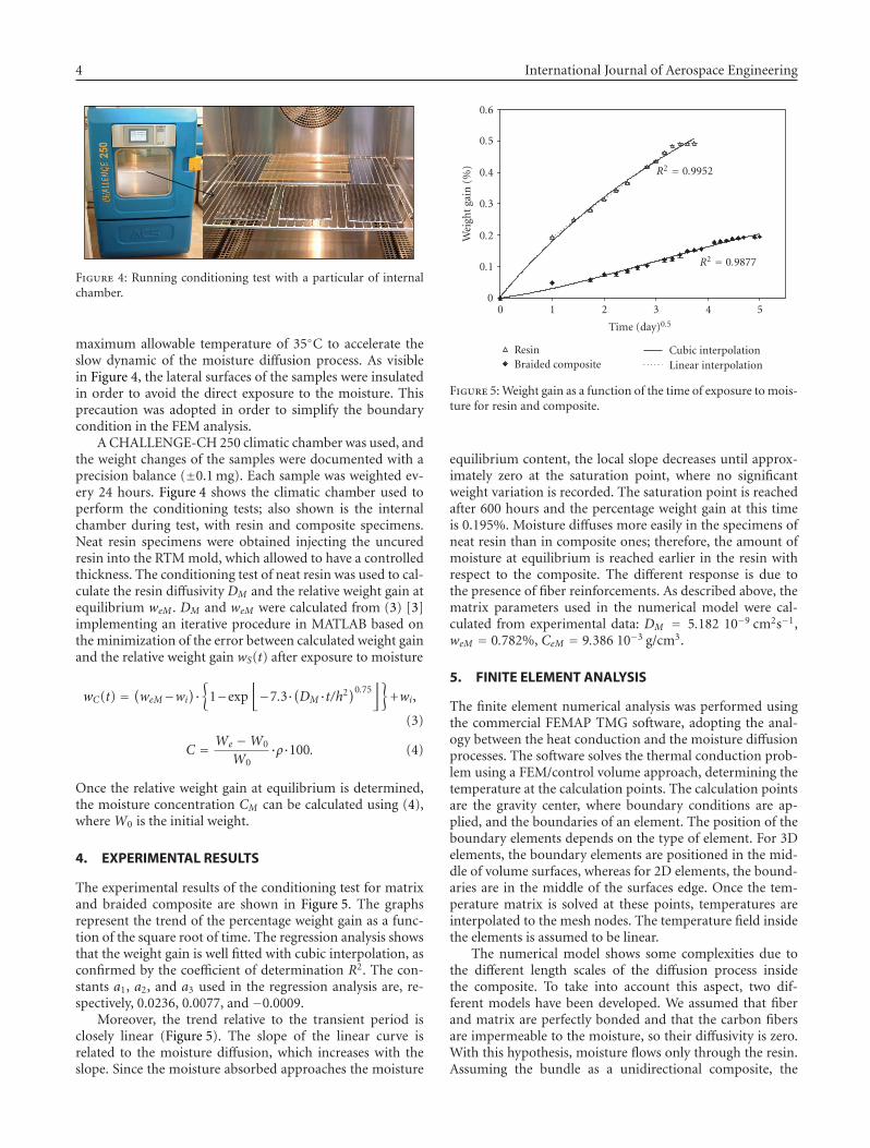
Figure 4: Running conditioning test with a particular of internalchamber.
maximum allowable temperature of 35◦C to accelerate theslow dynamic of the moisture diffusion process. As visiblein Figure 4, the lateral surfaces of the samples were insulatedin order to avoid the direct exposure to the moisture. Thisprecaution was adopted in order to simplify the boundarycondition in the FEM analysis.
A CHALLENGE-CH 250 climatic chamber was used, andthe weight changes of the samples were documented with aprecision balance (±0.1 mg). Each sample was weighted ev-ery 24 hours. Figure 4 shows the climatic chamber used toperform the conditioning tests; also shown is the internalchamber during test, with resin and composite specimens.Neat resin specimens were obtained injecting the uncuredresin into the RTM mold, which allowed to have a controlledthickness. The conditioning test of neat resin was used to cal-culate the resin diffusivity DM and the relative weight gain atequilibrium weM . DM and weM were calculated from (3) [3]implementing an iterative procedure in MATLAB based onthe minimization of the error between calculated weight gainand the relative weight gain wS(t) after exposure to moisture
wC(t) = (weM−wi)·{
1−exp⌊−7.3·(DM·t/h2)0.75
⌋}+wi,
(3)
C = We −W0
W0·ρ·100. (4)
Once the relative weight gain at equilibrium is determined,the moisture concentration CM can be calculated using (4),where W0 is the initial weight.
4. EXPERIMENTAL RESULTS
The experimental results of the conditioning test for matrixand braided composite are shown in Figure 5. The graphsrepresent the trend of the percentage weight gain as a func-tion of the square root of time. The regression analysis showsthat the weight gain is well fitted with cubic interpolation, asconfirmed by the coefficient of determination R2. The con-stants a1, a2, and a3 used in the regression analysis are, re-spectively, 0.0236, 0.0077, and −0.0009.
Moreover, the trend relative to the transient period isclosely linear (Figure 5). The slope of the linear curve isrelated to the moisture diffusion, which increases with theslope. Since the moisture absorbed approaches the moisture
0 1 2 3 4 5
Time (day)0.5
0
0.1
0.2
0.3
0.4
0.5
0.6
Wei
ghtg
ain
(%)
ResinBraided composite
Cubic interpolationLinear interpolation
R2 = 0.9877
R2 = 0.9952
Figure 5: Weight gain as a function of the time of exposure to mois-ture for resin and composite.
equilibrium content, the local slope decreases until approx-imately zero at the saturation point, where no significantweight variation is recorded. The saturation point is reachedafter 600 hours and the percentage weight gain at this timeis 0.195%. Moisture diffuses more easily in the specimens ofneat resin than in composite ones; therefore, the amount ofmoisture at equilibrium is reached earlier in the resin withrespect to the composite. The different response is due tothe presence of fiber reinforcements. As described above, thematrix parameters used in the numerical model were cal-culated from experimental data: DM = 5.182 10−9 cm2s−1,weM = 0.782%, CeM = 9.386 10−3 g/cm3.
5. FINITE ELEMENT ANALYSIS
The finite element numerical analysis was performed usingthe commercial FEMAP TMG software, adopting the anal-ogy between the heat conduction and the moisture diffusionprocesses. The software solves the thermal conduction prob-lem using a FEM/control volume approach, determining thetemperature at the calculation points. The calculation pointsare the gravity center, where boundary conditions are ap-plied, and the boundaries of an element. The position of theboundary elements depends on the type of element. For 3Delements, the boundary elements are positioned in the mid-dle of volume surfaces, whereas for 2D elements, the bound-aries are in the middle of the surfaces edge. Once the tem-perature matrix is solved at these points, temperatures areinterpolated to the mesh nodes. The temperature field insidethe elements is assumed to be linear.
The numerical model shows some complexities due tothe different length scales of the diffusion process insidethe composite. To take into account this aspect, two dif-ferent models have been developed. We assumed that fiberand matrix are perfectly bonded and that the carbon fibersare impermeable to the moisture, so their diffusivity is zero.With this hypothesis, moisture flows only through the resin.Assuming the bundle as a unidirectional composite, the
S. Laurenzi et al. 5
diffusivity parallel to the bundle direction is equivalent to thematrix diffusivity, while the diffusivity normal to the bundledirection is coincident with the diffusivity into the bundle,that is, the matrix diffusivity in microscale. This parameterwas determined performing the thermal analysis of the RUCbundle model and then setting the material properties of thecarbon-braided RUC. Simulations were run after definingthe RUC models, the material properties, and the numericalconvergence.
In order to reduce the computational cost due to the largenumber of elements of carbon-braided RUC, we consideredthe tow as an isotropic material with diffusivity equal to thediffusivity normal to the tow directionsDFn. This assumptionwas supported considering that the moisture flow is directedalong the thickness of the material, the z-axis. In fact, theangle between the z-axis and the fibers direction varies from90◦ to 81◦.
The postprocessing was carried out using two programs:the first one imports the mass of the elements in two ma-trices, for tow and resin, respectively, and calculates the to-tal mass. The second program receives in input the vectorof the temperature of the elements and the matrices deter-mined from the first program. The mass variation is calcu-lated by multiplying the temperature of every element forWe and the corresponding mass. Then, the relative massgain is determined by dividing such variation for the start-ing mass. These two programs have been implemented inMATLAB.
5.1. Model of the RUC bundle
The particular geometry of the bundle permits to con-sider only the cross section, reducing the analysis to a two-dimensional problem. The first step to build the model isto determine the area that represents the RUC. In order todo that, the fibers distribution, the number of fiber filament,and the correspondent fiber volume fraction have to be de-fined. Previous works on unidirectional fibers have shownthat a random distribution gives closer agreement with theexperimental data than a regular one. This can be explainedconsidering that in a random distribution there are zoneswith high fiber density that creates a barrier for moisturediffusion. On the other hand, a regular fiber distribution ischaracterized by a uniform distance among the fibers, whichgenerates paths for the moisture flux.
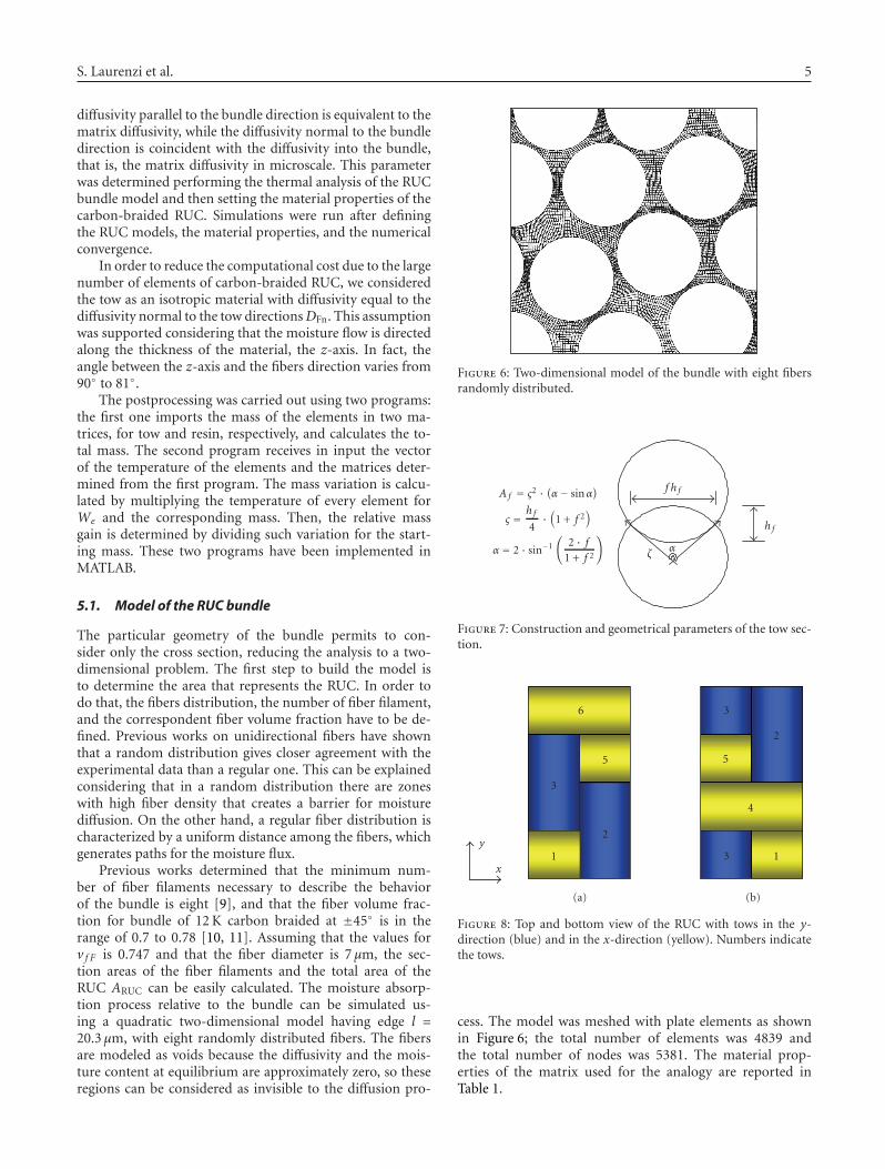
Previous works determined that the minimum num-ber of fiber filaments necessary to describe the behaviorof the bundle is eight [9], and that the fiber volume frac-tion for bundle of 12 K carbon braided at ±45◦ is in therange of 0.7 to 0.78 [10, 11]. Assuming that the values forv f F is 0.747 and that the fiber diameter is 7 μm, the sec-tion areas of the fiber filaments and the total area of theRUC ARUC can be easily calculated. The moisture absorp-tion process relative to the bundle can be simulated us-ing a quadratic two-dimensional model having edge l =20.3 μm, with eight randomly distributed fibers. The fibersare modeled as voids because the diffusivity and the mois-ture content at equilibrium are approximately zero, so theseregions can be considered as invisible to the diffusion pro-
Figure 6: Two-dimensional model of the bundle with eight fibersrandomly distributed.
ζα
f h f
h f
A f = σ2 · (α− sinα)
σ = h f4·(
1 + f 2)
α = 2 · sin−1
(2 · f
1 + f 2
)
Figure 7: Construction and geometrical parameters of the tow sec-tion.
y
x1
2
3
5
6
3 1
4
5
2
3
(a) (b)
Figure 8: Top and bottom view of the RUC with tows in the y-direction (blue) and in the x-direction (yellow). Numbers indicatethe tows.
cess. The model was meshed with plate elements as shownin Figure 6; the total number of elements was 4839 andthe total number of nodes was 5381. The material prop-erties of the matrix used for the analogy are reported inTable 1.
6 International Journal of Aerospace Engineering
Y
Z
X
00.5
11.5
22.5
33.544.5
55.566.5
77.588.5
99.5
1010.5
11
00.5
11.5
22.5
33.5
44.5
55.5
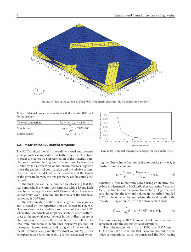
Figure 9: View of the carbon-braided RUC with matrix elements (blue) and fiber tow (yellow).
Table 1: Material properties associated with the bundle RUC usedfor the analogy.
Thermal conductivity kM = DM·CeR = 4.864·10−15
Specific heat cM = CeMρM
= 7.822 ·10−3
Matrix density ρM = 1.2 ·10−12
5.2. Model of the RUC-braided composite
The RUC-braided model is three-dimensional and presentssome geometric complexities due to the braided architecture.In order to create a true representation of the material, bun-dles are considered having lenticular sections. Each sectionis built by the intersection of two circumferences. Figure 7shows the geometrical construction and the relative param-eters used in the model; when the thickness and the lengthof the tows are known, the tow geometry can be completelydefined.
The thickness can be determined by observing that thereal composite is a 3 mm thick laminate with 4 layers. Eachlayer has an average thickness of 0.75 mm and two tows over-lap for every layer. Therefore, the thickness of the lenticularsection h f is 0.375 mm.
The determination of the bundle length is more complexand is based on the repetitive unit cell shown in Figure 8.Here, we show the top and bottom surfaces of a braided RUCschematization, which for simplicity is rotated of 45◦ with re-spect to the material axes; the tows in the y-direction are inblue, whereas the tows in the x-direction are in yellow. Thetows were numbered to define their respective position onthe top and bottom surface. Indicating with l the tow width,the RUC volume VRUC, and the tows total volume Vf TOT canbe expressed as a function of this; l is then calculated by set-
0.E + 00 1E + 04 2E + 04 3E + 04 4E + 04 5E + 04 6E + 04 7E + 04 8E + 04
Number of time step
0
0.015
0.03
0.045
0.06
0.075
0.09
Var
iati
onof
aver
age
tem
pera
ture
Figure 10: Temporal convergence analysis for the bundle RUC.
ting the fiber volume fraction of the composite vF = 0.5, asillustrated in the equation
vF =Vf TOT
VCRU= VFTOT·v f F
VCRU= 0.5. (5)
Equation(5) was numerically solved using an iterative pro-cedure implemented in MATLAB, after expressing VRUC andVf TOT as function of the geometric factor f (Figure 7) andconsidering that the tow total volume in the carbon-braidedRUC can be obtained by multiplying the total length of thetows d f TOT (equation (6)) with the cross-section area:
d f TOT =6∑i=ldi = 8·
(l +√l2 + 0.3752
). (6)
The results are h f = 10.759 mm and l = 4 mm, which are inagreement with the experimental observations.
The dimensions of a basic RUC are 5.657 mm ×11.318 mm× 0.375 mm. The RUC is not unique, but to min-imize computational costs, we considered the RUC having
S. Laurenzi et al. 7
00.06250.1250.1880.250.3130.3750.4380.50.5630.6250.6880.750.8130.8750.9381
Time 0 s
(a)
00.06250.1250.1880.250.3130.3750.4380.50.5630.6250.6880.750.8130.8750.9381
Time 100 s
(b)
00.06250.1250.1880.250.3130.3750.4380.50.5630.6250.6880.750.8130.8750.9381
Time 1000 s
(c)
00.06250.1250.1880.250.3130.3750.4380.50.5630.6250.6880.750.8130.8750.9381
Time 3000 s
(d)
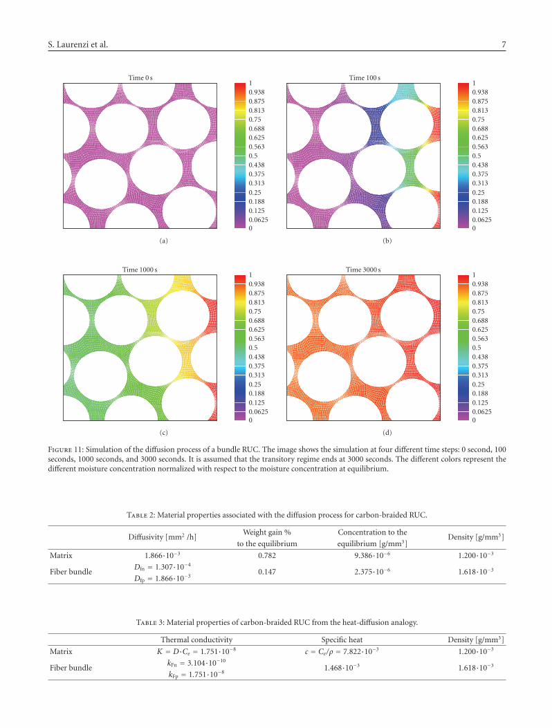
Figure 11: Simulation of the diffusion process of a bundle RUC. The image shows the simulation at four different time steps: 0 second, 100seconds, 1000 seconds, and 3000 seconds. It is assumed that the transitory regime ends at 3000 seconds. The different colors represent thedifferent moisture concentration normalized with respect to the moisture concentration at equilibrium.
Table 2: Material properties associated with the diffusion process for carbon-braided RUC.
Diffusivity [mm2 /h]Weight gain % Concentration to the
Density [g/mm3]to the equilibrium equilibrium [g/mm3]
Matrix 1.866·10−3 0.782 9.386·10−6 1.200·10−3
Fiber bundleDfn = 1.307·10−4
0.147 2.375·10−6 1.618·10−3
Dfp = 1.866·10−3
Table 3: Material properties of carbon-braided RUC from the heat-diffusion analogy.
Thermal conductivity Specific heat Density [g/mm3]
Matrix K = D·Ce = 1.751·10−8 c = Ce/ρ = 7.822·10−3 1.200·10−3
Fiber bundlekFn = 3.104·10−10
1.468·10−3 1.618·10−3
kFp = 1.751·10−8
8 International Journal of Aerospace Engineering
the smallest dimensions. In any case, a single RUC is suf-ficient to investigate the moisture diffusion process in sta-tionary conditions, yet not during the transitory regime.In fact, moisture already diffuses in the adjacent RUC be-fore reaching the equilibrium: in this case, the absorptionoccurs through the thickness. Considering that the com-posite is manufactured with four layers, a model based onfour overlapping RUCs should be adopted. The symmetryof the laminate and the boundary conditions of the mediumplane reduce the number of RUCs to two overlapping uni-tary cells. The model was meshed using 22480 elementsand 6233 nodes, using the three-dimensional solid elementsCHEXA and CTETRA. Figure 9 shows the carbon-braidedRUC model used for the analysis: the matrix zones are inblue, while the yellow indicates the fiber zones.
After defining the model, it is necessary to determine thethermal properties of the materials using the analogy be-tween absorption and heat conduction; these properties arereported in Tables 2 and 3.
6. NUMERICAL RESULTS
6.1. Fem analysis of moisture diffusion in bundle RUC
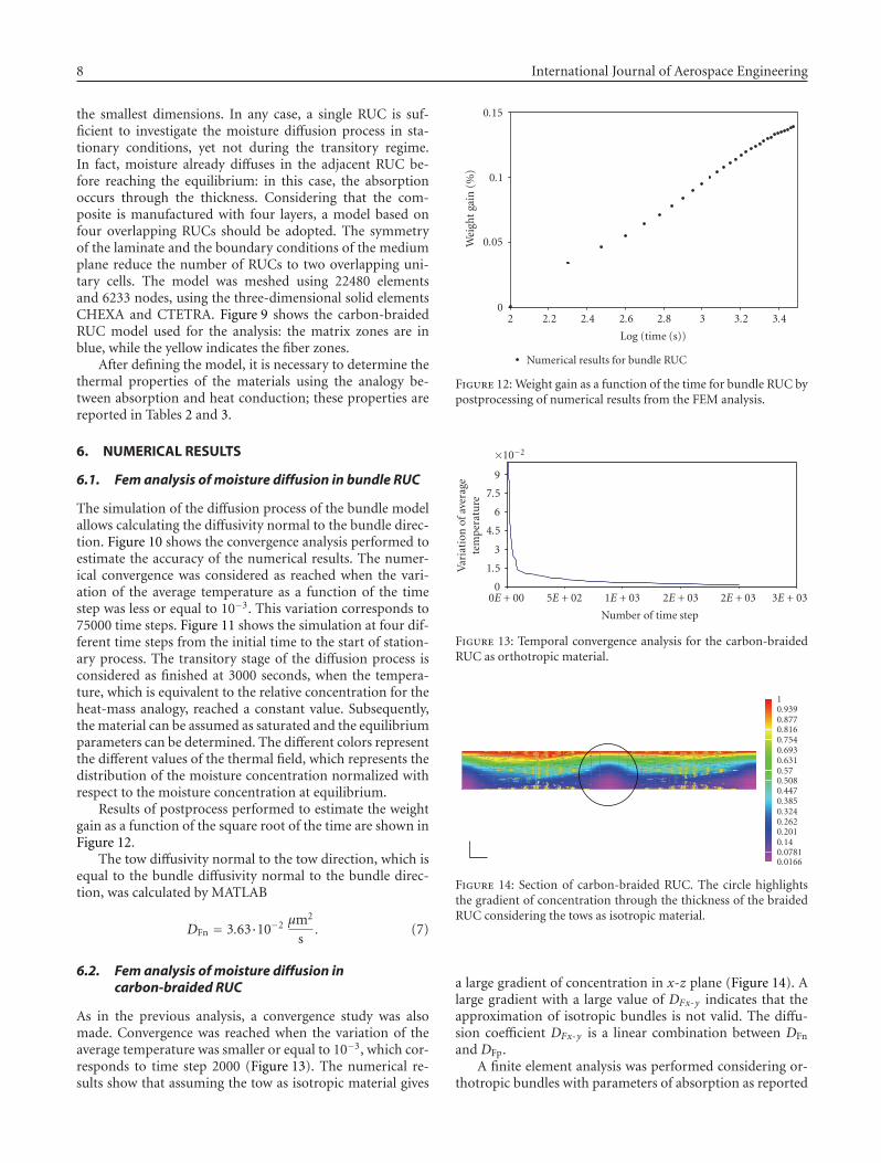
The simulation of the diffusion process of the bundle modelallows calculating the diffusivity normal to the bundle direc-tion. Figure 10 shows the convergence analysis performed toestimate the accuracy of the numerical results. The numer-ical convergence was considered as reached when the vari-ation of the average temperature as a function of the timestep was less or equal to 10−3. This variation corresponds to75000 time steps. Figure 11 shows the simulation at four dif-ferent time steps from the initial time to the start of station-ary process. The transitory stage of the diffusion process isconsidered as finished at 3000 seconds, when the tempera-ture, which is equivalent to the relative concentration for theheat-mass analogy, reached a constant value. Subsequently,the material can be assumed as saturated and the equilibriumparameters can be determined. The different colors representthe different values of the thermal field, which represents thedistribution of the moisture concentration normalized withrespect to the moisture concentration at equilibrium.
Results of postprocess performed to estimate the weightgain as a function of the square root of the time are shown inFigure 12.
The tow diffusivity normal to the tow direction, which isequal to the bundle diffusivity normal to the bundle direc-tion, was calculated by MATLAB
DFn = 3.63·10−2 μm2
s. (7)
6.2. Fem analysis of moisture diffusion incarbon-braided RUC
As in the previous analysis, a convergence study was alsomade. Convergence was reached when the variation of theaverage temperature was smaller or equal to 10−3, which cor-responds to time step 2000 (Figure 13). The numerical re-sults show that assuming the tow as isotropic material gives
2 2.2 2.4 2.6 2.8 3 3.2 3.4
Log (time (s))
0
0.05
0.1
0.15
Wei
ght
gain
(%)
Numerical results for bundle RUC
Figure 12: Weight gain as a function of the time for bundle RUC bypostprocessing of numerical results from the FEM analysis.
0E + 00 5E + 02 1E + 03 2E + 03 2E + 03 3E + 03
Number of time step
0
1.5
3
4.5
6
7.5
9V
aria
tion
ofav
erag
ete
mpe
ratu
re
×10−2
Figure 13: Temporal convergence analysis for the carbon-braidedRUC as orthotropic material.
0.01660.07810.140.2010.2620.3240.3850.4470.5080.570.6310.6930.7540.8160.8770.9391
Figure 14: Section of carbon-braided RUC. The circle highlightsthe gradient of concentration through the thickness of the braidedRUC considering the tows as isotropic material.
a large gradient of concentration in x-z plane (Figure 14). Alarge gradient with a large value of DFx-y indicates that theapproximation of isotropic bundles is not valid. The diffu-sion coefficient DFx-y is a linear combination between DFn
and DFp.A finite element analysis was performed considering or-
thotropic bundles with parameters of absorption as reported
S. Laurenzi et al. 9
0
0.0625
0.125
0.188
0.25
0.313
0.375
0.438
0.5
0.563
0.625
0.688
0.75
0.813
0.875
0.938
1
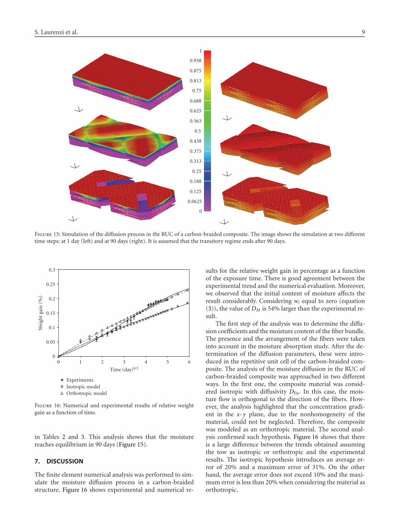
Figure 15: Simulation of the diffusion process in the RUC of a carbon-braided composite. The image shows the simulation at two differenttime steps: at 1 day (left) and at 90 days (right). It is assumed that the transitory regime ends after 90 days.
0 1 2 3 4 5 6
Time (day)0.5
0
0.05
0.1
0.15
0.2
0.25
0.3
Wei
ght
gain
(%)
ExperimentsIsotropic modelOrthotropic model
Figure 16: Numerical and experimental results of relative weightgain as a function of time.
in Tables 2 and 3. This analysis shows that the moisturereaches equilibrium in 90 days (Figure 15).
7. DISCUSSION
The finite element numerical analysis was performed to sim-ulate the moisture diffusion process in a carbon-braidedstructure. Figure 16 shows experimental and numerical re-
sults for the relative weight gain in percentage as a functionof the exposure time. There is good agreement between theexperimental trend and the numerical evaluation. Moreover,we observed that the initial content of moisture affects theresult considerably. Considering wi equal to zero (equation(3)), the value of DM is 54% larger than the experimental re-sult.
The first step of the analysis was to determine the diffu-sion coefficients and the moisture content of the fiber bundle.The presence and the arrangement of the fibers were takeninto account in the moisture absorption study. After the de-termination of the diffusion parameters, these were intro-duced in the repetitive unit cell of the carbon-braided com-posite. The analysis of the moisture diffusion in the RUC ofcarbon-braided composite was approached in two differentways. In the first one, the composite material was consid-ered isotropic with diffusivity DFn. In this case, the mois-ture flow is orthogonal to the direction of the fibers. How-ever, the analysis highlighted that the concentration gradi-ent in the x-y plane, due to the nonhomogeneity of thematerial, could not be neglected. Therefore, the compositewas modeled as an orthotropic material. The second anal-ysis confirmed such hypothesis. Figure 16 shows that thereis a large difference between the trends obtained assumingthe tow as isotropic or orthotropic and the experimentalresults. The isotropic hypothesis introduces an average er-ror of 20% and a maximum error of 31%. On the otherhand, the average error does not exceed 10% and the maxi-mum error is less than 20% when considering the material asorthotropic.
10 International Journal of Aerospace Engineering
The percentage weight gain is higher in the orthotropicmodel than in the isotropic model, due to the concentrationgradients in the x-y plane. For concentration gradient, thediffusivity is a linear combination of the diffusivities in thex-y plane. Therefore, in isotropic materials, the diffusivity isconstant in all directions, whereas in orthotropic materials,the diffusivity is one order magnitude higher than the otherdirection. The approximation introduced with the assump-tion of isotropic material reduces the accuracy considerably.However, the orthotropic model improves the accuracy ofthe results, but it increases the computational time cost ofapproximately four times with respect to the isotropic case.
8. CONCLUSIONS
The methodology developed in this study allows simulatingthe process of moisture diffusion in a composite braided ma-terial with sufficient approximation starting from a limitedset of experimental data. We developed an analysis that re-duces drastically the number of experimental tests necessaryto understand the behavior of a composite material in mois-ture environment. At the same time, the analysis decreasesconsiderably the design costs and times. A commercial codefor FEM analysis was used to estimate in few hours and withgood approximation the weight gain as a function of time,which normally requires several months of experiments.
REFERENCES
[1] M. S. Amer, M. J. Koczak, and L. S. Schadler, “Relating hy-drothermal degradation in single fibre composites to degrada-tion behaviour in bulk composites,” Composites Part A, vol. 27,no. 9, pp. 861–867, 1996.
[2] “Guidelines for Property Testing of Composites,” Vol. 3, MIL-HDBK-17-1F, 2002.
[3] “Structural Materials Handbook,” Vol. 1, section III, ESA PSS-03-203, 1994.
[4] L.-R. Bao and A. F. Yee, “Effect of temperature on moistureabsorption in a bismaleimide resin and its carbon fiber com-posites,” Polymer, vol. 43, no. 14, pp. 3987–3997, 2002.
[5] L.-R. Bao and A. F. Yee, “Moisture diffusion and hygrother-mal aging in bismaleimide matrix carbon fiber composites:part II—woven and hybrid composites,” Composites Scienceand Technology, vol. 62, no. 16, pp. 2111–2119, 2002.
[6] J. Zhou and J. P. Lucas, “The effects of a water environmenton anomalous absorption behavior in graphite/epoxy com-posites,” Composites Science and Technology, vol. 53, no. 1, pp.57–64, 1995.
[7] Y. Z. Wan, Y. L. Wang, H. L. Luo, X. H. Dong, and G. X. Cheng,“Moisture absorption behavior of C3D/EP composite and ef-fect of external stress,” Materials Science and Engineering A,vol. 326, no. 2, pp. 324–329, 2002.
[8] K. Kondo and T. Taki, “Moisture diffusivity of unidirectionalcomposites,” Journal of Composite Materials, vol. 16, pp. 82–93, 1982.
[9] J.-E. Lundgren and P. Gudmundson, “Moisture absorptionin glass-fibre/epoxy laminates with transverse matrix cracks,”Composites Science and Technology, vol. 59, no. 13, pp. 1983–1991, 1999.
[10] X. Tang, J. D. Whitcomb, Y. Li, and H.-J. Sue, “Microme-chanics modeling of moisture diffusion in woven composites,”
Composites Science and Technology, vol. 65, no. 6, pp. 817–826,2005.
[11] P. Vaddadi, T. Nakamura, and R. P. Singh, “Inverse analysisfor transient moisture diffusion through fiber-reinforced com-posites,” Acta Materialia, vol. 51, no. 1, pp. 177–193, 2003.
[12] P. Vaddadi, T. Nakamura, and R. P. Singh, “Transient hy-grothermal stresses in fiber reinforced composites: a heteroge-neous characterization approach,” Composites Part A, vol. 34,no. 8, pp. 719–730, 2003.
[13] J. H. Lienhard IV and J. H. Lienhard V, A Heat Transfer Text-book, Phlogiston Press, Cambridge, Mass, USA, 3rd edition,2001.
[14] J.-H. Byun, “The analytical characterization of 2-D braidedtextile composites,” Composites Science and Technology, vol. 60,no. 5, pp. 705–716, 2000.
[15] T. Zeng, L.-Z. Wu, and L.-C. Guo, “Mechanical analysis of 3Dbraided composites: a finite element model,” Composite Struc-tures, vol. 64, no. 3-4, pp. 399–404, 2004.

International Journal of
AerospaceEngineeringHindawi Publishing Corporationhttp://www.hindawi.com Volume 2010
RoboticsJournal of
Hindawi Publishing Corporationhttp://www.hindawi.com Volume 2014
Hindawi Publishing Corporationhttp://www.hindawi.com Volume 2014
Active and Passive Electronic Components
Control Scienceand Engineering
Journal of
Hindawi Publishing Corporationhttp://www.hindawi.com Volume 2014
International Journal of
RotatingMachinery
Hindawi Publishing Corporationhttp://www.hindawi.com Volume 2014
Hindawi Publishing Corporation http://www.hindawi.com
Journal ofEngineeringVolume 2014
Submit your manuscripts athttp://www.hindawi.com
VLSI Design
Hindawi Publishing Corporationhttp://www.hindawi.com Volume 2014
Hindawi Publishing Corporationhttp://www.hindawi.com Volume 2014
Shock and Vibration
Hindawi Publishing Corporationhttp://www.hindawi.com Volume 2014
Civil EngineeringAdvances in
Acoustics and VibrationAdvances in
Hindawi Publishing Corporationhttp://www.hindawi.com Volume 2014
Hindawi Publishing Corporationhttp://www.hindawi.com Volume 2014
Electrical and Computer Engineering
Journal of
Advances inOptoElectronics
Hindawi Publishing Corporation http://www.hindawi.com
Volume 2014
The Scientific World JournalHindawi Publishing Corporation http://www.hindawi.com Volume 2014
SensorsJournal of
Hindawi Publishing Corporationhttp://www.hindawi.com Volume 2014
Modelling & Simulation in EngineeringHindawi Publishing Corporation http://www.hindawi.com Volume 2014
Hindawi Publishing Corporationhttp://www.hindawi.com Volume 2014
Chemical EngineeringInternational Journal of Antennas and
Propagation
International Journal of
Hindawi Publishing Corporationhttp://www.hindawi.com Volume 2014
Hindawi Publishing Corporationhttp://www.hindawi.com Volume 2014
Navigation and Observation
International Journal of
Hindawi Publishing Corporationhttp://www.hindawi.com Volume 2014
DistributedSensor Networks
International Journal of