Embed Size (px)
Citation preview

Chair of Power ElectronicsChristian-Albrechts-Universität zu KielKaiserstraße 224143 Kiel
Modeling of Power Converters Connected to the Electrical Grid
Prof. Marco Liserre, PhD, IEEE fellowHead of the Chair of Power [email protected]
Marco Liserre, Zhixiang Zou, Roberto Rosso, Giovanni De Carne

Chair of Power Electronics | Prof. Marco Liserre | [email protected] 1
Contents
Model Deepness of Grid-connected Power Converter
Modeling of PWM Converters
Current Control of PWM Converters
Grid Synchronization for Three-phase Power Converter
Power and dc Control of Grid-connected Power Converter

Chair of Power Electronics | Prof. Marco Liserre | [email protected] 2
Model Deepness of Grid-connected Power Converter

Chair of Power Electronics | Prof. Marco Liserre | [email protected] 3
DC-link capacitor
Semiconductors or voltage source?
AC filter
Inner control loop
Outer control loop
Only electrical or thermal too?
PLL
Key Components of Modeling

Chair of Power Electronics | Prof. Marco Liserre | [email protected] 4
Stability issues:
AC small signal stability
Sub-Synchronous signal stability
DC voltage stability
AC transient stability
Frequency stability
High PE integration
Interaction among controllersOff-shore wind connection
HVDC + governor interactionHybrid AC/DC grids
Multi-terminal DC gridsLow Voltage Ride Through
Angle/Voltage stability with PEHigh PE penetration impact on system
Virtual Inertia strategies
Grid Integration Studies

Chair of Power Electronics | Prof. Marco Liserre | [email protected] 5
A Mapping between the Forms of Harmonic Instability and Components
Source: X. Wang and F. Blaabjerg, "Harmonic Stability in Power Electronic Based Power Systems: Concept, Modeling, and Analysis," IEEE Transactions on Smart Grid, in press.

Chair of Power Electronics | Prof. Marco Liserre | [email protected] 6
Linearized Modeling Methods for Power Converters
Source: X. Wang and F. Blaabjerg, "Harmonic Stability in Power Electronic Based Power Systems: Concept, Modeling, and Analysis," IEEE Transactions on Smart Grid, in press.

Chair of Power Electronics | Prof. Marco Liserre | [email protected] 7
Goal:Study the harmonic behavior of power electronics-based converter.
Issue:Converter’s inner controller may resonate with the passive elements of the grid (e.g., filter).Focus on modeling:The PLL has to be included in the model to consider low order harmonic resonances. Difference of converter self-admittance with
or without PLL modeled
AC Small-signal Stability

Chair of Power Electronics | Prof. Marco Liserre | [email protected] 8
0 1 2 3 4 5 6 7 8
Time (s)
-4
-2
0
2
4
Mag
nitu
de (p
u)
LPB to Gen torque
0 1 2 3 4 5 6 7 8
Time (s)
-4
-2
0
2
4
Mag
nitu
de (p
u)
Phase a current
0 1 2 3 4 5 6 7 8
Time (s)
-2
-1
0
1
2
Mag
nitu
de (p
u)
Electromagnetic torque
Goal:Study the low order (<50Hz) phenomena.
Issue:HVDC controller interacts with turbine-generation shaft, oscillating at low frequency.Focus on modeling:The outer control loop modeling impacts on the oscillation observed. Difference between PQ control mode (blue
line) and Vdc control mode (red line) of HVDC systems connected to a wind park
AC sub-synchronous signal stability
Chair of Power Electronics | Prof. Marco Liserre | [email protected] 9
Difference of DC-link modeling during a power variation
Goal:Study the voltage stability and its dynamic behavior in DC grids.
Issue:Fast power variations have an impact on the grid stability and on the component stress
Focus on modeling:The DC-link passive components modeling shall be considered to evaluate the stability.
DC Voltage Stability

Chair of Power Electronics | Prof. Marco Liserre | [email protected] 10
Goal:Study the grid behavior during large disturbances (e.g., faults)
Issue:HVDC DC-link voltage are affected by large AC voltage variations and voltage control loop dynamics.Focus on modeling:The inner control loop (voltage/current) shall be considered for stability issues. (a) Phasorial, and (b) average model
including inner control loop of HVDC converters
Transient stability

Chair of Power Electronics | Prof. Marco Liserre | [email protected] 11
Goal:Estimate the frequency stability in micro-/ ST-based grids under fast power variations.
Issue:PLL and DC-link dynamics may interact, leading to large frequency oscillations.
Focus on modeling:PLL and DC-link models must be considered to avoid under-estimation of frequency issue. Difference of DC-link modeling during a
power variation
Frequency stability
Chair of Power Electronics | Prof. Marco Liserre | [email protected] 12
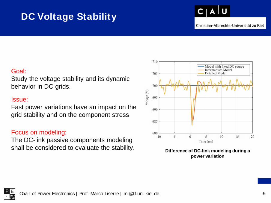
Com
plex
ityof
the
mod
elModeling deepness scale

Chair of Power Electronics | Prof. Marco Liserre | [email protected] 13
Two possibilities: Class D
• Ideal DC-link (piloted voltage source)• ideal PLL (infinite bandwidth)
Class C• Capacitor model included• Simplified PLL model (only dynamic)
Difference of DC-link modeling during a power variation
CLASS C is the minimum requirement!
Modeling Scale - Example 1:Frequency Stability

Chair of Power Electronics | Prof. Marco Liserre | [email protected] 14
Difference of DC-link modeling during a power variation
Three possibilities: Class D
• Ideal DC-link (voltage source)• Equivalent control model (dynamic)
Class C• Capacitor model included• Equivalent control model
Class B• Capacitor model included• Detailed control modelCLASS C is sufficient for stability studies!
Modeling Scale - Example 2:dc Transient Voltage Stability
Source: Report of M.Sc. Freiber Rojas, Karlsruhe Institute of Technology

Chair of Power Electronics | Prof. Marco Liserre | [email protected] 16
Switching Ripple due to PWM
Source: R.W. Erickson and D. Maksimovic, Fundamentals of Power Electronics. Springer US, 2001.
Chair of Power Electronics | Prof. Marco Liserre | [email protected] 17
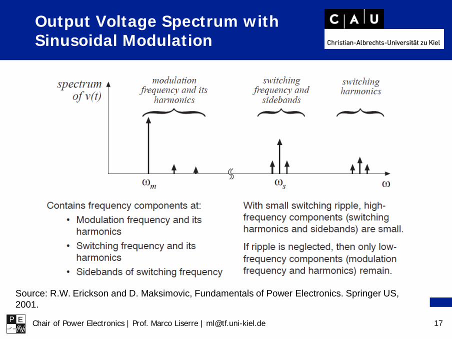
Output Voltage Spectrum with Sinusoidal Modulation
Source: R.W. Erickson and D. Maksimovic, Fundamentals of Power Electronics. Springer US, 2001.

Chair of Power Electronics | Prof. Marco Liserre | [email protected] 18
Averaging to Remove Switching Ripple
Chair of Power Electronics | Prof. Marco Liserre | [email protected] 19
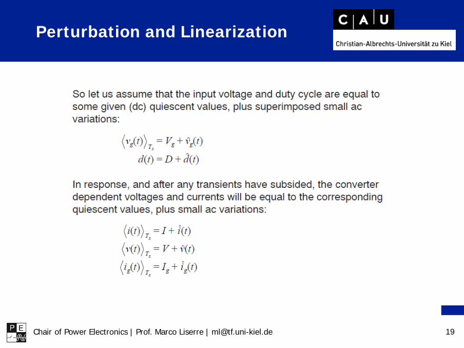
Perturbation and Linearization

Chair of Power Electronics | Prof. Marco Liserre | [email protected] 21
Perturbation of Inductor Equation

Chair of Power Electronics | Prof. Marco Liserre | [email protected] 22
Perturbation of Inductor Equation

Chair of Power Electronics | Prof. Marco Liserre | [email protected] 23
Neglect of Second-order Terms

Chair of Power Electronics | Prof. Marco Liserre | [email protected] 24
Linearized Inductor Equation

Chair of Power Electronics | Prof. Marco Liserre | [email protected] 25
TopologyConsiderations:
• The switches are ideal
• The output filter is an inductor and a resistor
• Ts is the switching period
Equations of the circuit: The average voltage over one switching period is:
Modeling of the Single-Phase Inverter
Chair of Power Electronics | Prof. Marco Liserre | [email protected] 26
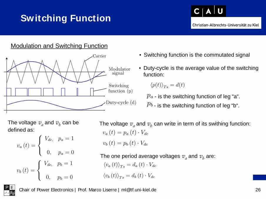
Modulation and Switching Function • Switching function is the commutated signal
• Duty-cycle is the average value of the switching function:
- is the switching function of leg “a“.- is the switching function of leg “b“.
The voltage va and vb can be defined as:
The voltage va and vb can write in term of its swithing function:
The one period average voltages va and vb are:
Switching Function

Chair of Power Electronics | Prof. Marco Liserre | [email protected] 27
(1)
(2)
(3)
(4)
Previous equations: Replace (3) and (4) in (1):
For the modulation strategy:
Then, equation (5) becomes:
(6)
(5)
The average equation of the ac side and the equivalent average circuit are shown below:
Equivalent average circuit of the ac side
Modeling of the ac Side

Chair of Power Electronics | Prof. Marco Liserre | [email protected] 28
(6)
Thus, the average equivalent circuit of the dc side is:
Equivalent average circuit of the dc side
Equation of the circuit:
The leg currents are related with the switching function by:
Replacing (7) in (6):
(7)
The average dc current over one switching period is:
Modeling of the dc Side

Chair of Power Electronics | Prof. Marco Liserre | [email protected] 29
Combining the equivalent circuits of the ac side and dc side, it is obtained the equivalent average circuit of the single-phase converter.
Average Model of the Inverter

Chair of Power Electronics | Prof. Marco Liserre | [email protected] 30
Modeling of the Three-Phase Inverter
Topology with L filter:
The switching function:
where:
The ac voltage equation:
Equations of the circuit:

Chair of Power Electronics | Prof. Marco Liserre | [email protected] 31
The ac voltage equation: Equations of the circuit:
From αβ reference frame to dq reference frame
Modeling of the Three-Phase Inverter

Chair of Power Electronics | Prof. Marco Liserre | [email protected] 32
The ac voltage equation in αβ frame : Equations of the circuit:
From αβ reference frame to dq reference frame
The ac voltage equation in dq frame :
Modeling of the Three-Phase Inverter

Chair of Power Electronics | Prof. Marco Liserre | [email protected] 33
Modeling of the Three-Phase Inverter
The ac voltage equation in αβ frame :
From αβ reference frame to dq reference frame
The ac voltage equation in dq frame :
( ) ( ) ( ) ( ) ( )
( )( ) ( ) ( ) ( )
1
1
dq d d d dc
qd q q q dc
di ti t Ri t e t p t V
dt Ldi t
i t Ri t e t p t Vdt L
ω
ω
− = − − +
+ = − − +
Average circuit of the ac side in dq-frame:

Chair of Power Electronics | Prof. Marco Liserre | [email protected] 34
Equivalent average circuit of the dc side:
The current of dc side can be described in terms of the switching function and output current, as:
Pertubing and linearizing the previous equation, the main dc side current equation is obtained:
Modeling of the dc Side

Chair of Power Electronics | Prof. Marco Liserre | [email protected] 35
Equivalent Circuit
Equivalent average circuit of the three-phase inverter in dq-frame:

Chair of Power Electronics | Prof. Marco Liserre | [email protected] 36
Equivalent average circuit of the dc side:
Equivalent average circuit of the three-phase inverter in dq-frame:
Modeling of the dc Side

Chair of Power Electronics | Prof. Marco Liserre | [email protected] 37
Current Control of PWM Converters

Chair of Power Electronics | Prof. Marco Liserre | [email protected] 38
PWM current control methods
ON/OFF controllers with pulse width modulator
hysteresis predictive optimized
linear Non - linear
fuzzy passivity
PI predictive Dead - beat
resonant repetitive
38
Current Control Overview
Source: R. Teodorescu, M. Liserre, and P. Rodriguez, Grid Converters for Photovoltaic and Wind Power Systems. John Wiley & Sons, 2011.

Chair of Power Electronics | Prof. Marco Liserre | [email protected] 39
• Typically PI controllers are used for the current loop in grid inverters• Technical optimum design (damping 0.707 overshoot 5%)
gv
v∗ i( )dG s ( )fG s( )PIG si∗
e
+− ++ +−
( ) IPI P
kG s ks
= +
1( )1 1.5d
s
G sT s
=+
( ) 1( )( )f
i sG sv s R Ls
= =+
-1 -0.5 0 0.5 1
-1
-0.8
-0.6
-0.4
-0.2
0
0.2
0.4
0.6
0.8
1
10-1 100 101 102 103 104-20
-15
-10
-5
0
Mag
nitu
de (D
b)
100 101 102 103 104-400
-300
-200
-100
0
Frequency (Hz)
Pha
se (D
egre
e)
PI Current Control
Source: R. Teodorescu, M. Liserre, and P. Rodriguez, Grid Converters for Photovoltaic and Wind Power Systems. John Wiley & Sons, 2011.

Chair of Power Electronics | Prof. Marco Liserre | [email protected] 40
• When the current controlled inverter is connected to the grid, the phaseerror results in a power factor decrement and the limited disturbancerejection capability leads to the need of grid feed-forward compensation
• However the imperfect compensation action of the feed-forward controldue to the background distortion results in high harmonic distortion of thecurrent and consequently non-compliance with international power qualitystandards
0 0.002 0.004 0.006 0.008 0.01 0.012 0.014 0.016 0.018 0.02-0.2
0
0.2
0.4
0.6
0.8
1
error (scaled)
referenceactual
time [s]0 0.005 0.01 0.015 0.02 0.025 0.03 0.035 0.04
-1.5
-1
-0.5
0
0.5
1
error
actualreference
0.019 0.0192 0.0194 0.0196 0.0198 0.02 0.0202 0.0204 0.0206 0.0208 0.021
-0.25
-0.2
-0.15
-0.1
-0.05
0
0.05
0.1
0.15
0.2
0.023 0.0235 0.024 0.0245 0.025 0.0255 0.026 0.0265 0.027 0.02750.8
0.82
0.84
0.86
0.88
0.9
0.92
0.94
0.96
0.98
1
time [s]
steady-state magnitude and phase errorlimited disturbance rejection capability
Shortcomings of PI controller
Source: R. Teodorescu, M. Liserre, and P. Rodriguez, Grid Converters for Photovoltaic and Wind Power Systems. John Wiley & Sons, 2011.

Chair of Power Electronics | Prof. Marco Liserre | [email protected] 41
• Resonant control is based on the use of Generalized Integrator (GI)• A double integrator achieves infinite gain at a certain frequency, called resonance
frequency, and almost no attenuation outside this frequency
• The GI will lead to zero stationary error and improved and selective disturbancerejection as compared with PI controller
101
102
103
-180
-90
0
90
180
Phas
e (de
g)
Bode Diagram
Frequency (Hz)
-200
-100
0
100
200
Magn
itude
(dB)
time [s]
inpu
t and
out
put o
f the
reso
nant
con
trolle
r
2 2
ss ω+
2 2
ss ω+
GI
Resonant Control

Chair of Power Electronics | Prof. Marco Liserre | [email protected] 42
Grid Synchronization for Three-phase Power Converter

Chair of Power Electronics | Prof. Marco Liserre | [email protected] 43
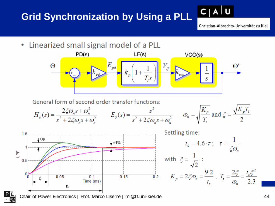
Grid Synchronization by Using a PLL
Chair of Power Electronics | Prof. Marco Liserre | [email protected] 44
Grid Synchronization by Using a PLL

Chair of Power Electronics | Prof. Marco Liserre | [email protected] 45
Synchronous Reference Frame PLL (SRF-PLL)

Chair of Power Electronics | Prof. Marco Liserre | [email protected] 46
SRF-PLL under Unbalanced and Distorted Grid
Source: R. Teodorescu, M. Liserre, and P. Rodriguez, Grid Converters for Photovoltaic and Wind Power Systems. John Wiley & Sons, 2011.

Chair of Power Electronics | Prof. Marco Liserre | [email protected] 47
SRF-PLL under Unbalanced and Distorted Grid
Source: R. Teodorescu, M. Liserre, and P. Rodriguez, Grid Converters for Photovoltaic and Wind Power Systems. John Wiley & Sons, 2011.

Chair of Power Electronics | Prof. Marco Liserre | [email protected] 48
During the last decade control structures emulating the behaviour of a synchronous machine (SM)have been proposed. Such control structures have been categorized as virtual synchronousmachines (VSMs).
Since they can reproduce the power-synchronization mechanism of a SM, they do not need adedicated unit for synchronation to the grid. The generalized structure of a power-synchronization based control is reported below:
Source: R. Rosso, S. Engelken, and M. Liserre, ” A generalized formulation of active power synchronization based control algorithms for grid connected converters,” in Proc. 44th IEEE IECON, Washington DC.
PLL-less Converters:General structure

Chair of Power Electronics | Prof. Marco Liserre | [email protected] 49
The synchronverter is among the most common control structuresproposed in the literature based on the power-synchronization mechanismof a SM.
Source: Q.-C. Zhong, P.-L. Nguyen, Z. Ma, and W. Sheng, ”Self-synchronized synchronverters: inverters without a dedicated synchronization unit,” IEEE Trans. Power Electron., vol. 29, no. 2, pp. 617-630, Feb. 2014.
Active power loop
Reactive power loop
PLL-less Converters: Synchronverter

Chair of Power Electronics | Prof. Marco Liserre | [email protected] 50
The Active power loop is described by the swing equationof a SM:
The reactive power loop reproduces a Q-V droop behaviour according to thecoefficient 𝐷𝐷𝑞𝑞:
𝐽𝐽ω̇ = 𝑇𝑇𝑚𝑚 − 𝑇𝑇𝑒𝑒 − 𝐷𝐷𝑝𝑝ω
Mechanical inertia
Rotor speed Mechanical torque
Electrical torque
Mechanicalfriction
Δ𝑄𝑄 = −𝐷𝐷𝑞𝑞Δ𝑉𝑉
Voltage deviation at the PCC
Reactive power setpoint variation
The synchronverterControl structure

Chair of Power Electronics | Prof. Marco Liserre | [email protected] 51
A linearized small-signal model of the synchronverter connected to the grid through an LCL filterhas been obtained for investigation purposes and a design procedure has been proposed.
The synchronverterSmall-signal model
Source: R. Rosso, J. Cassoli, S. Engelken, G. Buticchi, and M. Liserre, ”Analysis and Design of LCL Filter Based Synchronverter”, 2017 IEEE Energy conversion conference and exposition (ECCE), Cincinnati, 2017.R. Rosso, J. Cassoli, G. Buticchi, S. Engelken, and M. Liserre, ”Robust stability analysis of LCL filter based synchronverter under different grid conditions,” IEEE Trans. Power Electron., 2018, DOI 10.1109/TPEL.2018.2867040.
C G

Chair of Power Electronics | Prof. Marco Liserre | [email protected] 52
The synchronverterParallel operation
In order to study the interactions among synchronverters operating in parallel, thecomponent connection method (CCM) has been adopted in the reference.
It allows obtaining the state-space representation of a complex system connecting toeach other separated subsystem, whose state-space representations are known.
Source: R. Rosso, S. Engelken, and M. Liserre, ”Analysis of the behavior of synchronverters operating in parallel by means of component connection method,” in Proc. 2018 IEEE Energy Conversion Congress and Exposition (ECCE), Portland, OR, 2018.

Chair of Power Electronics | Prof. Marco Liserre | [email protected] 53
Once the state-space representation of the system is obtained, eigenvalue analysiscan be performed in order to assess system stability.
critical eigenvalues
Source: R. Rosso, S. Engelken, and M. Liserre, ”Analysis of the behavior of synchronverters operating in parallel by means of component connection method,” in Proc. 2018 IEEE Energy Conversion Congress and Exposition (ECCE), Portland, OR, 2018.
The synchronverterParallel operation

Chair of Power Electronics | Prof. Marco Liserre | [email protected] 54
Park transformation:
Small phase perturbation (<7deg):
Large phase perturbation (<38deg):
Modeling of PLL-based Converter
Source: Z. Zou and M. Liserre, Study of Phase-locked-loop-based Synchronization of Grid Inverter During Large Phase Jump. in ECCE, 2018.

Chair of Power Electronics | Prof. Marco Liserre | [email protected] 55
Average model:
Updating model with second-order terms:
Modeling of PLL-based Converter
Source: Z. Zou and M. Liserre, Study of Phase-locked-loop-based Synchronization of Grid Inverter During Large Phase Jump. in ECCE, 2018.
Chair of Power Electronics | Prof. Marco Liserre | [email protected] 56
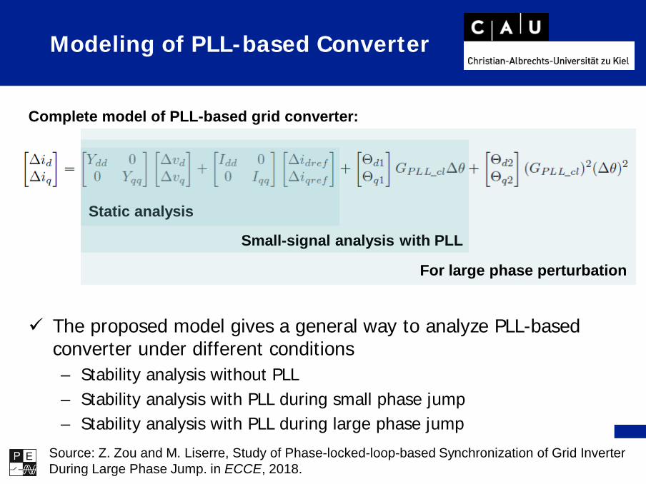
The proposed model gives a general way to analyze PLL-based converter under different conditions– Stability analysis without PLL– Stability analysis with PLL during small phase jump– Stability analysis with PLL during large phase jump
Complete model of PLL-based grid converter:
Static analysis
Small-signal analysis with PLL
For large phase perturbation
Modeling of PLL-based Converter
Source: Z. Zou and M. Liserre, Study of Phase-locked-loop-based Synchronization of Grid Inverter During Large Phase Jump. in ECCE, 2018.

Chair of Power Electronics | Prof. Marco Liserre | [email protected] 57
Stability Analysis with Different Models
Conventional small-signal
model
Higher accurate model
Stable
Unstable
An unstable case of PLL-based converter due to phase jump

Chair of Power Electronics | Prof. Marco Liserre | [email protected] 58
Interactions among PLL-basedconverters operating in parallel
A simplified converter model considering only the PLL in the inner control loop hasbeen adopted in order to investigate the interactions among PLL-based converters.
Impedance-based stability analysis has been performed for investigation purposes.

Chair of Power Electronics | Prof. Marco Liserre | [email protected] 59
Interactions among PLL-basedconverters operating in parallel
The problem formulation allows the calculation of a non-conservative stability marginbased on the small-gain theorem.
This not only allows to assess whether the system is stable or not, but also providesinformation about the robustness with respect to parameter variations.

Chair of Power Electronics | Prof. Marco Liserre | [email protected] 60
Interactions among PLL-basedconverters operating in parallel
Through a Monte Carlo analysis the following aspects have been highlighted:
The stability margin of a converter connected to the grid through a PLL decreases increasing thebandwidth of the PLL and the impedance of the grid.
The stability margin further decreases if there is another converter operating nearby.
The interactions among PLL based converters become stronger increasing the grid impedance.
Chair of Power Electronics | Prof. Marco Liserre | [email protected] 61
Power and dc Control of Grid-connected Power Converter

Chair of Power Electronics | Prof. Marco Liserre | [email protected] 62
Power Control in Synchronous Frame: PQ Open Loop Control
• Active and reactivepower feed-forwardcontrol
• Vdc control acts on thepower reference
d
q
qi di
i→
timetimeqi
ω
IP
kks
+
dcv
di∗
qi∗
dcV controller
PLLgv gv α
gv β
f gV
θ
je θ−
gdv
gqv
*vje θ−
iα
iβ
di
qi
di∗
di
gdv
qi∗
gqv
θ θ
je θ
vα∗
vβ∗
IP
kks
+
IP
kks
+
Lω−
Lω
i
2 2
1 gd gq
gq gdgd gq
v vv vv v
− +
gdv gqv
+-
+-
Currentcontroller
Currentcontroller
Σ
Σ
+- X
+-
dcV ∗
P∗
Q∗
αβ
abc
abc
αβabc
αβ
Source: R. Teodorescu, M. Liserre, and P. Rodriguez, Grid Converters for Photovoltaic and Wind Power Systems. John Wiley & Sons, 2011.

Chair of Power Electronics | Prof. Marco Liserre | [email protected] 63
Power Control in Stationary Frame: PQ Open Loop Control
• PLL may be avoided but it is used for making the control freq. adaptive and compute the first harmonic
• Active and reactive powerfeed-forward control
• Vdc control acts on thepower reference
β
α
iβ
iα
i→
time
time
iβ2 2
IP
k sks ω
++
iα∗
iβ∗
iiα
iβ
iα∗
iβ∗
vα∗
vβ∗
PLLgvgv α
gv β
θ,f ω
*v
dcV controller
IP
kks
+
2 2
1 g g
g gg g
v vv vv v
α β
β αα β
− +
gv α gv β
X
dcv
+-
+-
Currentcontroller
Currentcontroller
+-
+-
P∗
Q∗
dcV ∗
αβ
abc
abc
αβ
2 2I
Pk sk
s ω+
+
Source: R. Teodorescu, M. Liserre, and P. Rodriguez, Grid Converters for Photovoltaic and Wind Power Systems. John Wiley & Sons, 2011.

Chair of Power Electronics | Prof. Marco Liserre | [email protected] 64
+
iVSI
-v
-dcvC
+ +
-
TOTL
e
Produced power Delivered power
Capacitor power
Voltage decreases
+
iVSI
-v
-dcvC
+ +
-
TOTL
e
Produced power Delivered power
Capacitor power
Voltage increases
+
iVSI
-v
-dcvC
+ +
-
TOTL
e
Absorbed power Absorbed power
Capacitor power
Voltage increases
+
iVSI
-v
-dcvC
+ +
-
TOTL
e
Absorbed power Absorbed power
Capacitor power
Voltage decreases
DC Voltage Control
Source: R. Teodorescu, M. Liserre, and P. Rodriguez, Grid Converters for Photovoltaic and Wind Power Systems. John Wiley & Sons, 2011.

Chair of Power Electronics | Prof. Marco Liserre | [email protected] 65
• The control of the dc voltage through the ac current can result in theidentification of two loops, an outer dc voltage loop and an internalcurrent loop
• The internal loop is designed to achieve short settling times• On the other hand, the outer loop main goals are optimum regulation and
stability thus the voltage loop could be designed to be some what slower• Therefore, the internal and the external loops can be considered
decoupled
CC VC
synch
+
-
+- +-
dcv
dcv∗i
i∗Modulator
+
-
i TOTL
e
e *
(3 )2
sdc
dc
P n Tv
C v∆ +
∆ =⋅ ⋅
DC Voltage Control: Cascaded Control
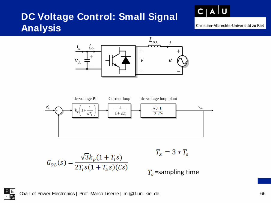
Chair of Power Electronics | Prof. Marco Liserre | [email protected] 66
+
-
+
-
+-
oi dci iTOTL
dcv v e
+-
11pI
ksT
+
dcv∗ 11 xsT+
dcv
dc-voltage loop plantCurrent loopdc-voltage PI
=sampling time
DC Voltage Control: Small Signal Analysis

Chair of Power Electronics | Prof. Marco Liserre | [email protected] 67
It must be nearby ωcr!!!
DC Voltage Control

Chair of Power Electronics | Prof. Marco Liserre | [email protected] 68
DC Loads
4 5 6 7 8 9
200
400
600
800
1000
-10 -9 -8 -7 -6 -5 -4
200
400
600
800
1000
0 1 2 3 4 5 6 7 80
200
400
600
800
1000
V/I characteristics
Step response (Load/Source step change)
Constant power load
Constant power source
Resistive load
Resistive load
Constant power load
Constant power source
Constant current load
Constant current source
CCL RL CPL
Overshoot 47 V 44 V 50 V
Settling time 0.153 s 0.153 s 0.155 s
Chair of Power Electronics | Prof. Marco Liserre | [email protected] 69
Conclusion
Model Deepness of Grid-connected Power Converter is related to the problem to be studied
Modeling of PWM Converters -> averaging and linearization
Current Control of PWM Converters -> generalized integrator
Grid Synchronization for Three-phase Power Converter -> PLL and power synchronization-based converters
Power and dc Control of Grid-connected Power Converter -> constant power case