Embed Size (px)
Citation preview

IEEE International Symposium on Industrial Electronics (ISlE 2009)Seoul Olympic Parktel, Seoul, Korea July 5-8, 2009
Modeling of a Variable Speed Wind Turbine with aPermanent Magnet Synchronous Generator
Alejandro Rolan', Alvaro Luna, Gerardo Vazquez,Daniel Aguilar
Electrical Department of EngineeringTechnical University of CataloniaColom 1- 08222-Terrassa, Spain
'Contact Author: [email protected]
Abstract:- The aim of this work is to analyze a typicalconfiguration of a Wind Turbine Generator System (WTGS)equipped with a Variable Speed Generator. Nowadays, doublyfed induction generators are being widely used on WTGS,although synchronous generators are being extensively utilizedtoo. There are different types of synchronous generators, but themulti-pole Permanent Magnet Synchronous Generator (PMSG) ischosen in order to obtain its model. It offers better performancedue to higher efficiency and less maintenance since it does nothave rotor current and can be used without a gearbox, which alsoimplies a reduction of the weight of the nacelle and a reduction ofcosts. Apart from the generator, the analyzed WTGS consists ofanother three parts: wind speed, wind turbine and drive train.These elements have been modeled and the equations that explaintheir behavior have been introduced. What is more, the wholeWTGS has been implemented in MATLAB/Simulink interface.Moreover, the concept of the Maximum Power Point Tracking(MPPT) has been presented in terms of the adjustment of thegenerator rotor speed according to instantaneous wind speed.
I. INTRODUCTION
The utilization of wind energy has a very long tradition.Some historians suggest that wind turbines (windmills) wereknown over 3000 years ago [1]. Until the early twentiethcentury wind power was used to provide mechanical power topump water or to grind grain.
The first wind turbines appeared at the beginning of the lastcentury and technology was improved step by step from theearly 1970s. By the end of the 1990s, wind energy has reemerged as one of the most important sustainable energyresources, partly because of the increasing price of the oil,security concerns of nuclear power and its environmentalissues. Moreover, as wind energy is abundant and it has aninexhaustible potential, it is one of the best technologies todayto provide a sustainable electrical energy supply to the worlddevelopment.
Actually, during the last decade of the twentieth century,worldwide wind capacity doubled approximately every threeyears. Currently, five countries (Germany, USA, Denmark,India and Spain) concentrate more than 83% of worldwidewind energy capacity in their countries [2]. Studies have shownthat by the end of 2003, the total installed capacity of the windturbines reached 39.234 GW and will exceed 110 GW by theyear of2012 [3].
978-1-4244-4349-9/09/$25.00 ©2009 IEEE
Gustavo AzevedoElectrical Department of Engineering and Power Systems
Federal University of Pernambuco (UFPE)Recife, Pernambuco Brazil
The need for increased power production from the wind andeconomic reasons, when the rated power of today's windturbines is still relatively small (2MW units are now typical),makes it necessary to group wind turbines into so-called windfarms.
Wind farms are built on land, but in recent years there hasbeen (and will probably be in the future) a strong trend towardslocating them offshore. The lack of suitable wind turbine siteson land (it is particularly the case of densely populatedcountries) and the highest wind speeds located near the sea(and consequently higher energy can be extracted from thewind) are the two main reasons for locating wind farmsoffshore. Horns Rev in Denmark [4] is an example of a currentoffshore wind farm, which is capable ofproducing 160 MW.
Both induction and synchronous generators can be used forwind turbine systems [6]. Mainly, three types of inductiongenerators are used in wind power conversion systems: cagerotor, wound rotor with slip control and doubly fed inductionrotors. The last one is the most utilized in wind speedgeneration because it provides a wide range of speed variation.However, the variable-speed directly-driven multi-polepermanent magnet synchronous generator (PMSG) windarchitecture is chosen for this purpose and it is going to bemodeled: it offers better performance due to higher efficiencyand less maintenance because it does not have rotor current.What is more, PMSG can be used without a gearbox, whichimplies a reduction of the weight of the nacelle and reductionof costs.
The present research article analyzes the model of a variablespeed wind turbine equipped with 2MW PMSG. It must benoted that the present research focuses neither on the converter(grid side and rotor side) nor on their controls.
II. SYSTEM DESCRIPTION
The system analyzed is a variable speed wind turbine basedon a multi-pole PMSG. Due to the low generator speed, therotor shaft is coupled directly to the generator, which meansthat no gearbox is needed. The generator is connected to thegrid via an AC/DCIAC converter, which consists of anuncontrolled diode rectifier, an internal DC-Link modeled as acapacitor and a PWM voltage-source inverter.
734

B. WindTurbine ModelThe rotor aerodynamics are presented by the well-known
static relations [I] , [2], [8], [9]
I 3t; =cP"2pAvw (2)
where P; is the power extracted from the wind [W], p is the airGrid density , which is equal to 1.225 kg/m' at sea level at
L ---'T1",-----J-.><-..r-----,temperature T = 288 K, Cp is the power coefficient, Vw is thewind speed upstream of the rotor [m/s] and A is the area sweptby the rotor [m2
] (A=71:R2, being R the radius of the blade [m]).
The amount of aerodynamic torque (rw ) in Nrn is given bythe ratio between the power extracted from the wind (Pw) , inW, and the turbine rotor speed (cow), in rad/s, as follows
DC/AC
C
DC-LinkAC/DC
PMSG
Turbine
A transformer is located between the inverter and the Pointof Common Connection (PCC) in order to raise the voltage byavoiding losses in the transport of the current. The layout of theelectrical part is depicted in Fig. I.
Fig. 1. Electrical scheme of a variable speed wind turbine equipped with adirect-drive PMSG.
where CO w is the angular velocity of rotor [rad/s], R is the rotorradius [m] and Vw is the wind speed upstream of the rotor [m/s].
(6)
(3)
(4)
(5)1
A + 0.089
where.9 is the pitch angle [0], which is the angle between theplane of rotation and the blade cross-section chord (Fig. 4), andthe tip-speed ratio A. is defined as
A = lO wR
Since this function depends on the wind turbine rotor type,the coefficients CrC6 and x can be different for variousturbines. The proposed coefficients [1] are equal to: c, = 0.5, C2
= 116, C3 = 0.4, c, = 0, cs = 5, C6 = 21 (x is not used becausec, = 0). Additionally, the parameter fJ is also defined indifferent ways [I], [2], [8]. For example, the parameter I/fJ in[I] is defined as
1
fJ
Pw' w=
lO w
It should be noted that the mechanical torque transmitted tothe generator (rw~) is the same as the aerodynamic torque,since there is no gearbox. It implies that the gearbox ratio isng = I. Therefore rw= rw~.
The power coefficient Cp reaches a maximum value equal toCp = 0.593 [9] which means that the power extracted from thewind is always less than 59.3% (Betz 's limit), because variousaerodynamic losses depend on the rotor construction (numberand shape of blades, weight, stiffuess, etc.). This is the wellknown low efficiency to produce electricity from the wind.
The power coefficient can be utilized in the form of look-uptables or in form of a function. The second approach ispresented below, where the general function defining thepower coefficient as a function of the tip-speed ratio and theblade pitch angle is defined as [8]
(1)
It must be noted that this study is dedicated to analyze andimplement the model from the wind turbine to the PMSG. Forthis reason, transformer, grid, rectifier and inverter models (andtheir controls) will not be considered.
III. S UBSYSTEM MODELS
8-Wind Speed
Fig. 3. Wind Speed model with Simulink.
where Vb is the base (constant) wind component, Vr is the rampwind component, vg is the gust wind component and Vn is thebase noise wind component, all of them in m/s.
Fig. 2. shows the graphics of the non-constant wind speedcomponents: ramp, gust and noise components.
The present work considers a constant wind speed equal to12 m/s. Consequently, the model implementation of the windspeed in Simulink implies the consideration of the base windspeed component, as shown in Fig. 3.
A. WindSpeedModelA model is required that can properly simulate the spatial
effect of wind behavior, including gusting, rapid (ramp)changes , and background noise. The wind speed is modeled asthe sum of the four components listed above [7]
tzc Q:~ v~Tsr T max t T sg T eg t t
Ramp Gust Random noise
Fig. 2. Non-constant wind speed components.
735
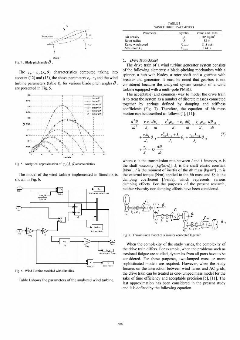
TABLE IWI ND TU RBINE PARAM ETERS
ParameterAir densityRotor radiusRated wind speedMaximum Cp
Symbol
PR
r.;»ep max
Value and Units1.205 kg/m'
38m11.8rn/s0.4412
(7)
C. Drive Train ModelThe drive train of a wind turbine generator system consists
of the following elements: a blade-pitching mechanism with aspinner, a hub with blades, a rotor shaft and a gearbox withbreaker and generator. It must be noted that gearbox is notconsidered because the analyzed system consists of a windturbine equipped with a multi-pole PMSG.
The acceptable (and common) way to model the drive trainis to treat the system as a number of discrete masses connectedtogether by springs defined by damping and stiffuesscoefficients (Fig. 7). Therefore, the equation of ith massmotion can be described as follows [1], [11]:
d 2()j
dt 2
When the complexity of the study varies, the complexity ofthe drive train differs. For example, when the problems such astorsional fatigue are studied , dynamics from all parts have to beconsidered. For these purposes, two-lumped mass or moresophisticated models are required. However, when the studyfocuses on the interaction between wind farms and AC grids ,the drive train can be treated as one-lumped mass model for thesake of time efficiency and acceptable precision [5], [11]. Thelast approximation has been considered in the present studyand it is defined by the following equation
Fig. 7. Transmission model ofN masses connected together.
where v, is the transmission rate between i and i-Imasses, c, isthe shaft viscosity [kg/(m's)], k, is the shaft elastic constant[N/m], J is the moment of inertia of the ith mass [kg-rrr'] , t, isthe external torque [Nrn] applied to the ith mass and D, is thedamping coefficient [N'm/s], which represents variousdamping effects . For the purposes of the present research,neither viscosity nor damping effects have been considered.
PwWind Power
Performance Coeflicient
Product
---+--- theta=QO
- x- theta= 5°~theta= 1 ()o
---e-- theta= 150
-B- theta=2QO
~theta;25'
0.5 i - ---r- ---,- - -,-- ---r- - F = = = =il
0.4
0.35
0.45
thetajni
Aerodynamic Torque
0.2
{!; 0.25
0.15
0.3
0 .1
Table I shows the parameters of the analyzed wind turbine.
Fig. 6. Wind Turbine modeled with Simulink.
Chord
Fig. 4 . Blade pitch angle .9 .
Fig. 5. Analytical approximation of Cp (/L , .9) characteristics.
The C p = C p (/L, .9) characteristics computed taking into
account (12) and (13), the above parameters Cr C6 and the wind
turbine parameters (table I), for various blade pitch angles.9,are presented in Fig. 5.
The model of the wind turbine implemented in Simulink isshown in Fig. 6.
736

(10)
(II)
Fig. 9. d-q and a-fJ axis of a typical salient-pole synchronous machine.
where p is the number of pole pairs of the generator.In order to complete the mathematical model of the PMSG
the mechanical equation is needed, and it is described by thefollowing electromagnetic torque equation [10]
The mathematical model of the PMSG for power system andconverter system analysis is usually based on the followingassumptions [9], [10]: the stator windings are positionedsinusoidal along the air-gap as far as the mutual effect with therotor is concerned; the stator slots cause no appreciablevariations of the rotor inductances with rotor position;magnetic hysteresis and saturation effects are negligible; thestator winding is symmetrical; damping windings are notconsidered; the capacitance of all the windings can beneglected and the resistances are constant (this means thatpower losses are considered constant).
The mathematical model of the PMSG in the synchronousreference frame (in the state equation form) is given by [10],[II]
where subscripts d and q refer to the physical quantities thathave been transformed into the d-q synchronous rotatingreference frame, R, is the stator resistance [n], Ld and Lq arethe inductances [H] of the generator on the d and q axis, L id andLlq are the leakage inductances [H] of the generator on the dand q axis, respectively, 'PI is the permanent magnetic flux[Wb] and We is the electrical rotating speed [rad/s] of thegenerator, defined by
nK Ie; 0Jeq 0.3 kg-rn'
1-t-"--~--1H 1wg
Symbol Value and UnitsParameterGear ratioRotational damping coefficientEquivalent inertia (turbin e+generator)
Fig. 8. Drive Train modeled with Simulink.
Table II shows the parameters of the drive train that has beenconsidered.
TABLE IIDRIVE TRAIN PARAMETERS
D. Generator ModelThe PMSG has been considered as a system which makes
possible to produce electricity from the mechanical energyobtained from the wind.
The dynamic model of the PMSG is derived from the twophase synchronous reference frame, which the q-axis is 90°ahead of the d-axis with respect to the direction of rotation.The synchronization between the d-q rotating reference frameand the abc-three phase frame is maintained by utilizing aphase locked loop (PLL) [10]. Fig. 9 shows the d-q referenceframe used in a salient-pole synchronous machine (which is thesame reference as the one used in a PMSG), where e is themechanical angle, which is the angle between the rotor d-axisand the stator axis.
doi, Te-Tw _g_Bm,w (8)dt J eq J eq g
where the sub-index g represents the parameters of thegenerator side, wg is the mechanical angular speed [rad/s] ofthe generator, Em is the damping coefficient [Nrn/s], t; is theelectromechanical torque [Nrn], Tw_g is the aerodynamic torquethat has been transferred to the generator side (3), which isequal to the torque produced in the rotor side because there isno gearbox, and Jeq is the equivalent rotational inertia of thegenerator [kg-rrr'], which is derived from [5]
Jeq=Jg+J; (9)ng
where Jg and J; are the generator and the rotor rotationalinertias [kg-rn"] respectively, ng is the gear ratio, which is equalto I, because no gearbox is utilized.
The model of the one mass drive train implemented inSimulink is depicted in Fig. 8.
737

Fig. 10 shows the equivalent circuit of the PMSG in de d-qsynchronous rotating reference frame. (13)
where wr opt is the optimum rotor speed [rad/s] and Pgen is themeasured generated power [W].
This is the base of the well-known Maximum Power PointTracking (MPPT) [12], [13]: from the prior treatment of thewind turbine model it can be appreciated that in order to extractthe maximum amount of power from the incident wind, Cp
should be maintained at a maximum. In order to achieve thisobjective, it can be appreciated from Fig. 5 that the speed ofthe generator rotor must be optimized according toinstantaneous wind speed (this optimization is achieved byusing (13)).j ~
j ~-(I). ' (Lq,+Lb ) • iq id
(I). ' ( (Ld,+L1,Hd+'I' r) iq
a) d-axis equivalent circ uit
r,
The Basic parameters of the PMSG are given in Table III.
Fig. 12. Power vs. speed curves for different wind speeds and optimum powergenerated as a function of generator speed and wind speed.
I-,--II
1.1 1.2 1.3 1.4
--+-- Pw at VW=8m1S : :
2.5 ---:- :: :~ ~:~~~~: __: ' __ -l __ -l __ { _
-e-- Pw at Vw=14m/s I
2 ~ Pg opt=Kp opt · w3 - -: - - - : - - ~ - - ~I I I I I I
I I I I I I I1.5 --1---1---1---1---1--...,-- --1 -
I I I I I I I
I I I I I I I I
1 - -:- - -:- - -:- - - :- - -: - - F-+-~'=~I I I I I I I
0.5 - -:- - -:- - _'-""--~: ""'-=7j(~- ~ --I ~, ; ' I -~.
I I I I I Io -- I- - - I - - - I- - - I- --I - - --j - --j - - - -t - -
I I I I I I I I
I I I I I I I I
-0.~.4 0.5 0.6 0.7 0.6 0.9w (pu)
b) q-axis equivalent circuit
u
Fig. 10. Equivalent circuit of the PMSG in the synchronous frame.
The model of the PMSG implemented in Simulink IS
depicted in Fig. 11.
flux
TABLE IIIGENERATOR PARAMETERS
Symbol
uq
ParameterRated generated powerRated mechanical speedStator resistan ceStator d-axis inductan ceStator q-axis inductanceStator leakage inductancePermanent magnet fluxPole pairs
P gen rated
W g rated
R,Ld.,
i ;LI,
'PIP
Value and Units2MW
2.18 rad/s0.08Q
0.334 H0.217 H
0.0334 H0.4832 Wb
3
R,
Fig. II . PMSG modeled with Simulink.
By analyzing the power produced by the wind turbine atvarious wind and rotor speeds, as depicted in Fig. 12, it can beappreciated that an optimum power coefficient constant Kp opt
exists. This coefficient show the generated power associatedwith the corresponding optimum rotor speed [1], [2], [8]. Kp opt
is calculated from individual wind turbine characteristics. Bymeasuring generated power, the corresponding optimum rotorspeed can be calculated and set as the reference speedaccording to [1]
IV. CONCLUSION
The modeling of a variable speed wind turbine with apermanent magnet synchronous generator has been treated.
The model has been implemented in MATLAB/Simulink inorder to validate it. CI' curves and power-speed characteristicshave been obtained.
The generator has been modeled in the d-q synchronousrotating reference frame, taking into account differentsimplifications. Moreover, the concept of the maximum powerpoint tracking has been presented in terms of the adjustment ofthe generator rotor speed according to instantaneous windspeed.
738

ACKNOWLEDGMENT
This research work has been developed under the grantENE2008-06588-C04-03/ALT from the Spanish Ministry ofScience and Technology.
REFERENCES
[1] Z. Lubosny. Wind Turbine Operation in Electric Power Systems. Berlin:Springer, 2003.
[2] T. Ackermann. Wind Power in Power Systems. New York: John Wiley &Sons, 2005.
[3] The American Wind Energy Association (2004, March). Global windpower growth continues to strengthen [Online]. Available:http://www.ewea.org.
[4] Horns Rev Offshore Wind Farm Technical Report (2007). Available:http://www.homsrev.dk.
[5] M. Yin, G.Li, M. Zhou and C. Zhao. "Modelling of the wind turbine withpermanent magnet synchronous generator for integration". IEEE PowerEngineering Society General Meeting, Tampa, Florida, 2007, pp. 1-6.
[6] J. G. Slootweg, S. W. H. de Haan, H. Polinder and W. L. Kling. "GeneralModel for Representing Variable Speed Wind Turbines in Power SystemDynamics Simulations". IEEE Transactions on Power Systems, vol. 18,no. 1,2003.
[7] P. M. Anderson and A. Bose. "Stability Simulation of Wind TurbineSystems". IEEE Transactions on Power Apparatus and Systems, vol.PAS-I02, no. 12,1983.
[8] S. Heier, Grid Integration of Wind Energy Conversion Systems. NewYork: John Wiley & Sons, 1998.
[9] 1. L. Rodriguez, 1.C. Burgos and L. Amalte. Sistemas E6licos deProduccion de Energia Electrica. Madrid: Editorial Rueda S.L, 2003.
[10] C. Krause. Analysis of electric machinery. 2nd Edition. United States ofAmerica: Willey, 2002.
[11] I. Boldea. Synchronous Generators. United States of America: Taylorand Francis, 2006.
[12] G. Ramtharan and N. Jenkins. "Modelling and Control of SynchronousGenerators for Wide-Range Variable-speed Wind Turbines". WindEnergy, Wiley Interscience, vol. 10, pp. 231-246, March 2007.
[13] M. Chinchilla, S. Arnaltes and 1. C. Burgos. "Control of PermanentMagnet Generators Applied to Variable-Speed Wind-Energy SystemsConnected to the Grid". IEEE Transactions on Energy Conversion,vol. 21, no. 1,2006.
739