Embed Size (px)
Citation preview
Modeling Process-Driven and Service-Oriented Architectures Using Patterns and
Pattern Primitives
Uwe Zdun Carsten Hentrich Schahram Dustdar
Distributed Systems Group Enterprise Content Management Solutions Distributed Systems Group
Information Systems Institute CSC Deutschland Solutions GmbH Information Systems Institute
Vienna University of Technology Germany Vienna University of Technology
Austria [email protected] Austria
[email protected] [email protected]
Abstract
Service-oriented architectures are increasingly used in the context of business processes. However, the proven
practices for process-oriented integration of services are not well documented yet. In addition, modeling approaches
for the integration of processes and services are neither mature nor do they exactly reflect the proven practices.
In this paper, we propose a pattern language for process-oriented integration of services to describe the proven
practices. Our main contribution is a modeling concept based on pattern primitives for these patterns. A pattern
primitive is a fundamental, precisely specified modeling element that represents a pattern. We present a catalog of
pattern primitives that are precisely modeled using OCL constraints and map these primitives to the patterns in the
pattern language of process-oriented integration of services. We also present a model validation tool that we have
developed to support modeling the process-oriented integration of services, and an industrial case study in which we
have applied our results.
1 Introduction
Service-oriented architectures (SOA) are an architectural style in which all functions, or services, are defined
using an interface description and have invokable, platform-independent interfaces that are called to perform business
processes [7, 3]. The top-level layer of many SOAs is a Service Composition Layer that deals with service-based
orchestration, coordination, or business processes [46]. In this paper, we consider architectures in which the Service
Composition Layer introduces a process engine. Services realize individual activities in the process (aka process
steps, tasks in the process). This kind of architecture is called process-driven SOA [19, 46].
1
Unfortunately, the design principles and proven practices (also referred to using the term “best practices”) behind
process-driven SOAs have not been well documented so far. Rather, the existing literature and approaches focus
on specific technologies. Examples are reference architectures and blueprints [39, 6, 40] or surveys on specific
composition techniques [34, 11, 10].
As an architectural style, process-driven SOAs are, however, in no way depending on specific technologies or
composition techniques. We and others have proposed software patterns as a way to support the general understand-
ing of the generic and stable aspects of SOA as an architectural style: A survey on SOA patterns can be found in [46].
On top of these patterns, we have described a pattern language that explains proven practices for process-oriented in-
tegration of services in a SOA (see [19]). These patterns have been identified and validated using a broad foundation
of industrial and open source systems, tools, and case studies (see also [19]).
One important problem, however, remains unsolved by these patterns: A software pattern is described in an
informal form and cannot easily be described formally or precisely, e.g., by using a parameterizable, template-style
description. Instead, patterns are describing many possible variants of a software solution, which are recognizable by
the human software designer as one and the same solution. This poses an important problem for the use of patterns
to document and model the proven practices in process-driven SOAs: The pattern instances are hard to trace in the
models and implementations. That is, without a good and constantly updated architectural documentation, the uses
of patterns, and hence the design considerations they encode, get lost as the software system evolves.
We aim to remedy these issues using the concept of pattern primitives. A pattern primitive is a fundamental,
precisely specified modeling element in a model that is representing a pattern [45]. We use the term “primitive”
because they are fundamental participants of a pattern and also the smallest units of abstraction that makes sense in
the domain of the pattern. In this paper, we apply the pattern primitive concept for the precise specification of proven
practices of process-driven SOAs.
Our modeling approach for process-driven SOAs relies on the observation that the various flow models in a
process-driven SOA – depicting different kinds of flows from long-running business processes to short-running tech-
nical processes – are central and interconnect the other relevant models, such as design, architecture, and language-
dependent models. In addition, we can generalize from the various kinds of flow models, because they are following
similar general modeling concepts, but require diverse extensions specific to the flow model type. Our general
approach to apply pattern primitives for process-driven SOAs is to use one kind of precisely specified modeling lan-
guage for all kinds of flow models that are used in a process-driven SOA. In this paper, we use (a precisely specified
sub-set of) UML2 activity diagrams to depict the various refinements of processes in process-driven SOA models,
even though our approach in general is not depending on the use of the UML.
This paper is structured as follows. In Section 2 we state the research problem tackled by the approach described
in this paper in more detail, and then in Section 3.1 we introduce our general concept to solve this research problem.
Our approach is then explained in the following sections in detail. An overview of this approach is presented in
Figure 1. First, in Section 3.2 we describe the pattern language for process-driven SOAs. We only give an overview
2

of the pattern language in this section. For details on the pattern language and the broad foundation of industrial and
open source systems, tools, and case studies from which we have identified the patterns, please refer to our earlier
work [19, 46]. The main conceptual contribution of this paper follows in the next two sections: In Section 4 we
introduce the pattern primitives that we have identified in the pattern language, as well as the UML2 models [32] and
OCL constraints [31] for the precise specification of these primitives in a UML profile (see [32]). In Section 5 we
explain how the pattern primitives can be used to precisely model the patterns. We have also validated our results in
two ways: In Section 6 we present a model-driven tool chain that we have developed to support our approach with
model validation. Section 7 discusses an industrial case study that we have conducted to validate our results in a
large-scale setting. Finally, Section 8 evaluates our approach in comparison to related work.
Industrial Case StudyIndustrial Case StudyIndustrial Process-Driven SOA System Case
Open Source SystemOpen Source SystemOpen Source System/Tool
Commercial ToolCommercial ToolCommercial System/Tool
Pattern Language for Process-Driven SOA
Existing Pattern Literature
Pattern Mining
Pattern Mining
Pattern Mining
Pattern Survey
Pattern Primitives for Process-Driven SOA
Identification of Pattern Primitives
Formal Representation of Pattern Primitives in UML2/OCL UML2 Profile for
Process-Driven SOA Pattern Primitives
Industrial Case Study
Model Validator Tool
Validation
Validation
Figure 1. Overview of the approach
2 Problem statement
In this section, we want to explain the problem addressed by this paper more precisely. The very idea of SOAs
suggests heterogeneity of technologies and integration across vendor-specific technologies [41]. This goal cannot
be reached, when the foundational concepts of a SOA are described using vendor-specific concepts and models,
or the SOA is described only in the context of a single composition technique. Hence, the main goal of the work
presented in this paper is to develop and validate a novel approach to model process-driven SOAs independently of
these implementation details, but in a way that allows our models to be precisely mapped to the details of particular
implementations and implementation technologies.
In particular, we aim to address this goal by solving the following five major (sub-)problems which are not yet
solved in their entirety by any other scientific or practical approach (see Section 8 for a comparison to this related
work):
1. Process-driven SOA is an architectural style, but there is no technology-neutral modeling approach so far that
can model all the relevant details of complex process-driven SOAs as they are built in practice.
2. On the one hand, SOAs should be modeled according to proven practices, on the other hand, those proven
3
practices are only documented informally (i.e., as software patterns) which cannot be used as elements of
precisely specified or formal/precise models because of their inherent variability (see Section 3.1).
3. Process-driven SOA models are hard to understand and be kept consistent because many different kinds of
models are relevant for a SOA and only loosely interconnected.
4. Design decisions in SOA models are hard to trace and can get violated during later evolution because they are
not precisely specified in the models.
5. Model-driven development of process-driven SOAs is not yet well supported because there are no precise
modeling approaches and model-driven development tools that are focusing on the domain of process-driven
SOA in general.
In this paper, we propose to tackle these problems using a novel concept for the precise specification of pattern
primitives that are used to model process-driven SOA patterns. In Section 8 we will summarize how this approach
solves each of the problems listed above.
3 Modeling process-driven SOAs using patterns and pattern primitives
3.1 A concept for modeling process-driven SOAs using pattern primitives
Software patterns and pattern languages have gained wide acceptance in the field of software development, because
they provide a systematic reuse strategy for design knowledge [35]. Each pattern is a three-part rule, which expresses
a relation between a certain context, a problem, and a solution. A pattern language is a collection of patterns that
solve the prevalent problems in a particular domain and context, and, as a language of patterns, it specifically focuses
on the pattern relationships in this domain and context.
Patterns informally describe many possible variants of one software solution that a human developer or designer
can recognize as one and the same solution – mainly because the human developer or designer can think creatively.
Just consider the popular Broker architectural pattern [4]. An experienced human developer or designer directly
recognizes whether a particular middleware platform follows the Broker pattern or not. This is a great strength of
the pattern approach and likely one of the reasons for the popularity of the approach. Patterns provide software
developers, designers, and architects with a common language which they can use throughout the design to identify
concepts that go beyond the formally recognizable structures in the source code and models (see [14]). Another
important aspect is that a pattern does not equal a specific component (or set of components) in the software design.
A pattern rather encodes proven practices for particular, recurring design decisions. A pattern language can thus be
seen as a language of design decisions that one can follow in a number of possible sequences.
Even though these properties of the pattern approach are highly valuable in the software design process, they also
make pattern instances hard to trace in the models and implementations. Consider again the Broker example: it is
4
almost impossible to precisely encode criteria for identifying any existing and future Broker implementation variant.
To overcome this problem, we propose to identify precisely specified primitive abstractions that can be found in the
patterns.
A software pattern has – per definition – numerous existing known uses in different software systems written by
different teams from different organizations. Likewise we require from a pattern primitive that it can be used to model
different patterns or different variants of one pattern. In our work we have validated this property by modeling pattern
known uses from different existing software systems using the elicited pattern primitive candidates. Only if a pattern
primitive can model different pattern known uses from different software systems, it is considered as sufficient and
appropriate, and included in our primitives catalog. Just like patterns are viewed by the pattern community as living
documents that change over time, for instance, because the technology for implementing the patterns changes and
thus new pattern variants or dependencies to other patterns emerge, pattern primitive catalogs must evolve and be
adapted, too.
A pattern primitive represents condensed knowledge from multiple sources: In the first place, primitives are
identified from the pattern literature. Primitives typically occur as participants of a number of related patterns. In our
work, once a primitive candidate had been identified, we have looked up different variants of the pattern in concrete
software systems (the known uses of the pattern), such as industrial software systems, open source systems, case
studies, etc. Next, we have developed a precise specification of the primitive that is generic enough to cover all
patterns and pattern known uses from which the primitive has been identified. Finally, we have applied the primitive
to model the patterns and pattern known uses, in order to validate that the found primitive is really a suitable modeling
construct for all of them. Only if all these steps had been successful, we have included the primitive in our primitives
catalog.
Documenting pattern primitives means to find precisely describable modeling elements that are primitive in the
sense that they represent basic units of abstraction in the domain of the pattern. For instance, if the domain is
software architecture, basic architectural abstractions like components, connectors, ports, and interfaces are used.
An interesting challenge in describing the pattern primitives for the patterns of process-driven SOA is that this area
is characterized by the fact that we need to understand various design and architecture concepts, as well as various
design and implementation languages, in order to be able to model a process-driven SOA design fully.
The different models that are relevant for a process-driven SOA come together in various kinds of “flow” models.
There are flow models for long-running business processes, activity steps in long-running processes, short-running
technical processes, and activity steps in short-running technical processes. Even though these flow models have
highly different semantic properties, they share the same basic flow abstraction concept, and at the same time they
are a kind of glue for all the other models that are involved in a process-driven SOA (such as architecture and design
models).
We have specified the primitives as extensions of UML2 metaclasses for each elicited primitive, using the stan-
dard UML extension mechanisms: stereotypes, tag definitions, and constraints (see [32]). We have also used the
5

Object Constraint Language (OCL) to precisely specify the constraints and provide more precise semantics for the
primitives. Our approach is in no way depending on the UML, any other modeling language can be chosen as well.
However, existing business process modeling notations, such as BPMN, would need to be extended with a precise
meta-model to apply our approach.
For the purposes of this paper, we model all kinds of process flows as UML2 activity diagrams. Please note that in
both cases, long-running business processes and short-running technical processes, additional information is needed.
For instance, to represent long-running business processes properly we must also depict organizational roles, orga-
nizational structures, business resources, etc. For short-running technical processes we must add technical details,
such as deployment information or technical resources. Sometimes this additional information can be specified us-
ing extensions of the activity diagrams (defined using stereotypes, tag definitions, and constraints); in other cases,
additional diagram types (such as class or component diagrams, or custom diagram types) are required to express the
relevant additional information. In the examples of this paper we omit these details because we want to concentrate
on the process/service interaction aspects.
3.2 Overview: Patterns for process-oriented integration of services in a SOA
Service Composition Layer
Macroflow Composition Layer
Macroflow Integration Layer
Dispatching Layer
Microflow Execution Layer
Business Application Services Layer
Figure 2. Sub-layers of the Service Composition Layer
In this section, we give an overview of the pattern language for process-oriented integration of services (for details
please refer to [19]). The pattern language basically addresses conceptual issues in the Service Composition Layer
of a SOA, when following a process-driven approach to services composition. In the Service Composition Layer, we
distinguish in our approach:
• Long-running, interruptible process flows which depict the business-oriented process perspective, called below
macroflow.
• Short-running transactional flows which depict the IT-oriented process perspective, called below microflow.
6

Between these two general flow model layers, an Integration Layer and a Dispatching Layer are introduced to support
architectural flexibility and scalability (see Figure 2).
The patterns and pattern relationships for designing a Service Composition Layer are shown in Figure 3. For space
reasons, we have concentrated on examples for the pattern primitives and pattern descriptions for a sub-set of this
pattern language (these patterns are rendered in grey).
In the pattern language, the pattern MACRO-MICROFLOW sets the scene and lays out the conceptual basis to
the overall architecture. The PROCESS-BASED INTEGRATION ARCHITECTURE pattern describes how to design an
architecture based on sub-layers for the Service Composition Layer, which is following the MACRO-MICROFLOW
conceptual pattern.
PROCESS-BASED INTEGRATION ARCHITECTURE
CONFIGURABLE ADAPTERREPOSITORY
PROCES INTEGRATIONADAPTER
manages
MACROFLOW INTEGRATIONSERVICE
RULE-BASED DISPATCHER
is realized with
forwards requests
delegates requests
offers
is composed of
MICROFLOW ENGINEBUSINESS-DRIVEN SERVICE
CONFIGURABLE ADAPTER
is realized with
manages
MACRO-MICROFLOW
conceptual foundation
is specialization of
MACROFLOW ENGINE
sends requests foractivity execution
interdependent design
is realized with
MICROFLOW EXECUTIONSERVICE
same service interface
Figure 3. Overview: Pattern language for process-oriented integration of services
The remaining patterns in the pattern language provide detailed guidelines for the design of a PROCESS-BASED
INTEGRATION ARCHITECTURE. In Figure 3 they are thus displayed within the boundaries of the PROCESS-BASED
INTEGRATION ARCHITECTURE pattern:
• The automatic functions required by macroflow activities from external systems are designed and exposed as
dedicated MACROFLOW INTEGRATION SERVICES.
• PROCESS INTEGRATION ADAPTERS connect the specific interface and technology of the process engine to an
integrated system.
7

• A RULE-BASED DISPATCHER picks up the (macroflow) activity execution requests and dynamically decides
based on (business) rules, where and when a (macroflow) activity is executed.
• A CONFIGURABLE ADAPTER connects to another system in a way that allows one to easily maintain the
connections, considering that interfaces may change over time.
• A CONFIGURABLE ADAPTER REPOSITORY manages CONFIGURABLE ADAPTERS as components, such that
they can be modified at runtime without affecting the systems sending requests to the adapters.
• A MICROFLOW EXECUTION SERVICE abstracts the technology specific API of the MICROFLOW ENGINE and
encapsulates the functionality of the microflow as a service.
• A MACROFLOW ENGINE allows for configuring business processes by flexibly orchestrating execution of
macroflow activities and the related business functions.
• A MICROFLOW ENGINE allows for configuring microflows by flexibly orchestrating execution of microflow
activities and the related BUSINESS-DRIVEN SERVICES.
• To define BUSINESS-DRIVEN SERVICES, high-level business goals are mapped to to-be macroflow business
process models that fulfill these goals and more fine grained business goals are mapped to activities within
these processes.
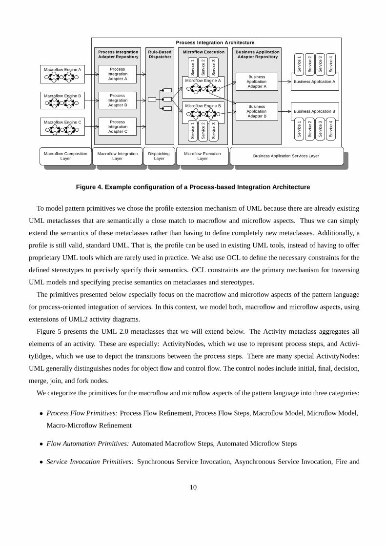
Figure 4 shows an exemplary configuration of a PROCESS-BASED INTEGRATION ARCHITECTURE, in which mul-
tiple macroflow engines execute the macroflows. Process-integration adapters are used to integrate the macroflows
with technical aspects. A dispatching layer enables scalability by dispatching onto a number of microflow engines.
Business application adapters connect to backends.
4 Pattern primitives in process-driven SOAs
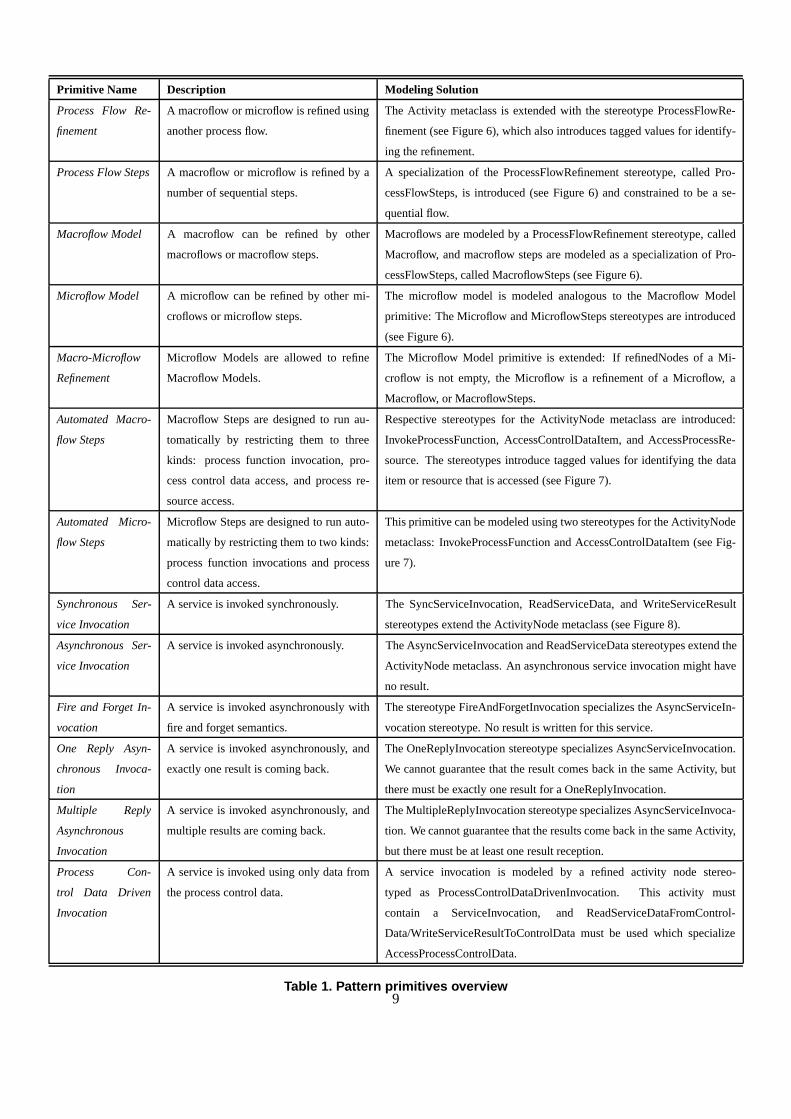
In this section, we present a catalog of pattern primitives identified from the patterns in Figure 3. Table 1 provides
an overview of these primitives. In the remainder of this section, for each primitive we provide a short description,
modeling problems, known uses in patterns, and a modeling solution in UML2/OCL. Before we present the individual
primitives, we briefly explain the extension mechanisms of UML2 and the excerpt of the UML2 meta-model that we
have extended (see [32]).
4.1 Extending the UML2 meta-model with macroflow and microflow aspects
The UML standard defines two ways to extend the UML language: an extension of the language meta-model,
which means a definition of a new member of the UML family of languages; a profile, which is a set of stereotypes,
tag definitions, and constraints that are based on existing UML elements with some extra semantics according to a
specific domain.
8
Primitive Name Description Modeling Solution
Process Flow Re-
finement
A macroflow or microflow is refined using
another process flow.
The Activity metaclass is extended with the stereotype ProcessFlowRe-
finement (see Figure 6), which also introduces tagged values for identify-
ing the refinement.
Process Flow Steps A macroflow or microflow is refined by a
number of sequential steps.
A specialization of the ProcessFlowRefinement stereotype, called Pro-
cessFlowSteps, is introduced (see Figure 6) and constrained to be a se-
quential flow.
Macroflow Model A macroflow can be refined by other
macroflows or macroflow steps.
Macroflows are modeled by a ProcessFlowRefinement stereotype, called
Macroflow, and macroflow steps are modeled as a specialization of Pro-
cessFlowSteps, called MacroflowSteps (see Figure 6).
Microflow Model A microflow can be refined by other mi-
croflows or microflow steps.
The microflow model is modeled analogous to the Macroflow Model
primitive: The Microflow and MicroflowSteps stereotypes are introduced
(see Figure 6).
Macro-Microflow
Refinement
Microflow Models are allowed to refine
Macroflow Models.
The Microflow Model primitive is extended: If refinedNodes of a Mi-
croflow is not empty, the Microflow is a refinement of a Microflow, a
Macroflow, or MacroflowSteps.
Automated Macro-
flow Steps
Macroflow Steps are designed to run au-
tomatically by restricting them to three
kinds: process function invocation, pro-
cess control data access, and process re-
source access.
Respective stereotypes for the ActivityNode metaclass are introduced:
InvokeProcessFunction, AccessControlDataItem, and AccessProcessRe-
source. The stereotypes introduce tagged values for identifying the data
item or resource that is accessed (see Figure 7).
Automated Micro-
flow Steps
Microflow Steps are designed to run auto-
matically by restricting them to two kinds:
process function invocations and process
control data access.
This primitive can be modeled using two stereotypes for the ActivityNode
metaclass: InvokeProcessFunction and AccessControlDataItem (see Fig-
ure 7).
Synchronous Ser-
vice Invocation
A service is invoked synchronously. The SyncServiceInvocation, ReadServiceData, and WriteServiceResult
stereotypes extend the ActivityNode metaclass (see Figure 8).
Asynchronous Ser-
vice Invocation
A service is invoked asynchronously. The AsyncServiceInvocation and ReadServiceData stereotypes extend the
ActivityNode metaclass. An asynchronous service invocation might have
no result.
Fire and Forget In-
vocation
A service is invoked asynchronously with
fire and forget semantics.
The stereotype FireAndForgetInvocation specializes the AsyncServiceIn-
vocation stereotype. No result is written for this service.
One Reply Asyn-
chronous Invoca-
tion
A service is invoked asynchronously, and
exactly one result is coming back.
The OneReplyInvocation stereotype specializes AsyncServiceInvocation.
We cannot guarantee that the result comes back in the same Activity, but
there must be exactly one result for a OneReplyInvocation.
Multiple Reply
Asynchronous
Invocation
A service is invoked asynchronously, and
multiple results are coming back.
The MultipleReplyInvocation stereotype specializes AsyncServiceInvoca-
tion. We cannot guarantee that the results come back in the same Activity,
but there must be at least one result reception.
Process Con-
trol Data Driven
Invocation
A service is invoked using only data from
the process control data.
A service invocation is modeled by a refined activity node stereo-
typed as ProcessControlDataDrivenInvocation. This activity must
contain a ServiceInvocation, and ReadServiceDataFromControl-
Data/WriteServiceResultToControlData must be used which specialize
AccessProcessControlData.
Table 1. Pattern primitives overview9
Process Integration Architecture
Process Integration Adapter Repository
Rule-Based Dispatcher
Microflow Execution Business Application Adapter Repository
Process Integration Adapter A
Process Integration Adapter B
Process Integration Adapter C
Microflow Engine ABusiness
Application Adapter A
Business Application Adapter B
Business Application A
Business Application B
Macroflow Engine A
Macroflow Engine B
Macroflow Engine C
Microflow Engine B
Ser
vice
1
Ser
vice
2
Ser
vice
3
Ser
vice
4
Ser
vice
1
Ser
vice
2
Ser
vice
3
Ser
vice
4
Ser
vice
1
Ser
vice
2
Ser
vice
3
Ser
vice
1
Ser
vice
2
Ser
vice
3
Macroflow CompositionLayer
Macroflow Integration Layer
Dispatching Layer
Microflow Execution Layer
Business Application Services Layer
Figure 4. Example configuration of a Process-based Integration Architecture
To model pattern primitives we chose the profile extension mechanism of UML because there are already existing
UML metaclasses that are semantically a close match to macroflow and microflow aspects. Thus we can simply
extend the semantics of these metaclasses rather than having to define completely new metaclasses. Additionally, a
profile is still valid, standard UML. That is, the profile can be used in existing UML tools, instead of having to offer
proprietary UML tools which are rarely used in practice. We also use OCL to define the necessary constraints for the
defined stereotypes to precisely specify their semantics. OCL constraints are the primary mechanism for traversing
UML models and specifying precise semantics on metaclasses and stereotypes.
The primitives presented below especially focus on the macroflow and microflow aspects of the pattern language
for process-oriented integration of services. In this context, we model both, macroflow and microflow aspects, using
extensions of UML2 activity diagrams.
Figure 5 presents the UML 2.0 metaclasses that we will extend below. The Activity metaclass aggregates all
elements of an activity. These are especially: ActivityNodes, which we use to represent process steps, and Activi-
tyEdges, which we use to depict the transitions between the process steps. There are many special ActivityNodes:
UML generally distinguishes nodes for object flow and control flow. The control nodes include initial, final, decision,
merge, join, and fork nodes.
We categorize the primitives for the macroflow and microflow aspects of the pattern language into three categories:
• Process Flow Primitives: Process Flow Refinement, Process Flow Steps, Macroflow Model, Microflow Model,
Macro-Microflow Refinement
• Flow Automation Primitives: Automated Macroflow Steps, Automated Microflow Steps
• Service Invocation Primitives: Synchronous Service Invocation, Asynchronous Service Invocation, Fire and
10

Activitynodeactivity
0..1*
ActivityEdge
edge
activity0..1
*
target
incoming
*
1
ActivityNode
source
outgoing
*
1
ObjectNode ControlNode
FinalNode
ActivityFinalNode FlowFinalNode
JoinNodeForkNode MergeNode DecisionNode InitialNode
Figure 5. UML2 activity diagram meta-model excerpt
Forget Invocation, One Reply Asynchronous Invocation, Multiple Reply Asynchronous Invocation, Process
Control Data Driven Invocation
Below each primitive is precisely specified in the context of the UML2 meta-model using OCL constraints. This
is a very important step for the practical applicability of our concepts: Without an unambiguous definition of the
primitives, they cannot be used (interchangeably) in UML2 tools and model-driven generators. That is, our main
reason for using the UML – a potential broad tool support – could otherwise not be supported.
Please note that we present the details of the primitive specifications because for us some of them are not obvious,
and they are needed for those readers interested in realizing the concepts. Readers, who want to get an overview of
our concepts first, can skip the rest of this section and continue reading in Section 5.
4.2 Process Flow Primitives
Primitive: Process Flow Refinement
Description: A process flow (macroflow or microflow) is refined using another process flow.
Modeling Problems: The closest construct in UML2 to a refinement relationship between process flows is the CallBe-
haviorAction, which indicates that a node in an activity invokes another activity (with the same name). This construct
could be used to model process flow refinements; however, the semantics are slightly different: A process flow refine-
ment is an ordinary node in a process with additional refinement (i.e. it has all properties of an activity node modeling
a process step), whereas a CallBehaviorAction is a pure invoking Action. In most typical macroflow/microflow sce-
narios, almost every macroflow is refined either by other macroflows or microflows. Hence, non-technical modelers
11
of macroflows would have to annotate almost every ActivityNode in their models with the “rake” symbol that indi-
cates a CallBehaviorAction. This is tedious and hard to understand for non-technical modelers. Technical modelers
of microflows, in turn, would have to use the same names for their Activities as used in the macroflow ActivityNodes
because CallBehaviorAction is matched by name, which might be inappropriate in the technical models. Finally,
CallBehaviorAction cannot be used to model situations where the refining activity is reused for different refined
nodes, because it can represent refinements only via the same name on the refining activity and the refined node.
Known Uses in Patterns: The MACRO-MICROFLOW pattern requires Process Flow Refinements as part of its solution.
The PROCESS-BASED INTEGRATION ARCHITECTURE pattern conceptually follows this solution. If MACROFLOW
ENGINE and MICROFLOW ENGINE are used together, or multiple instances of either engine are used, Process Flow
Refinements are used between the processes (not necessarily following the MACRO-MICROFLOW pattern). The con-
vergence of business and technical aspects in BUSINESS DRIVEN SERVICES is usually realized via Process Flow
Refinements.
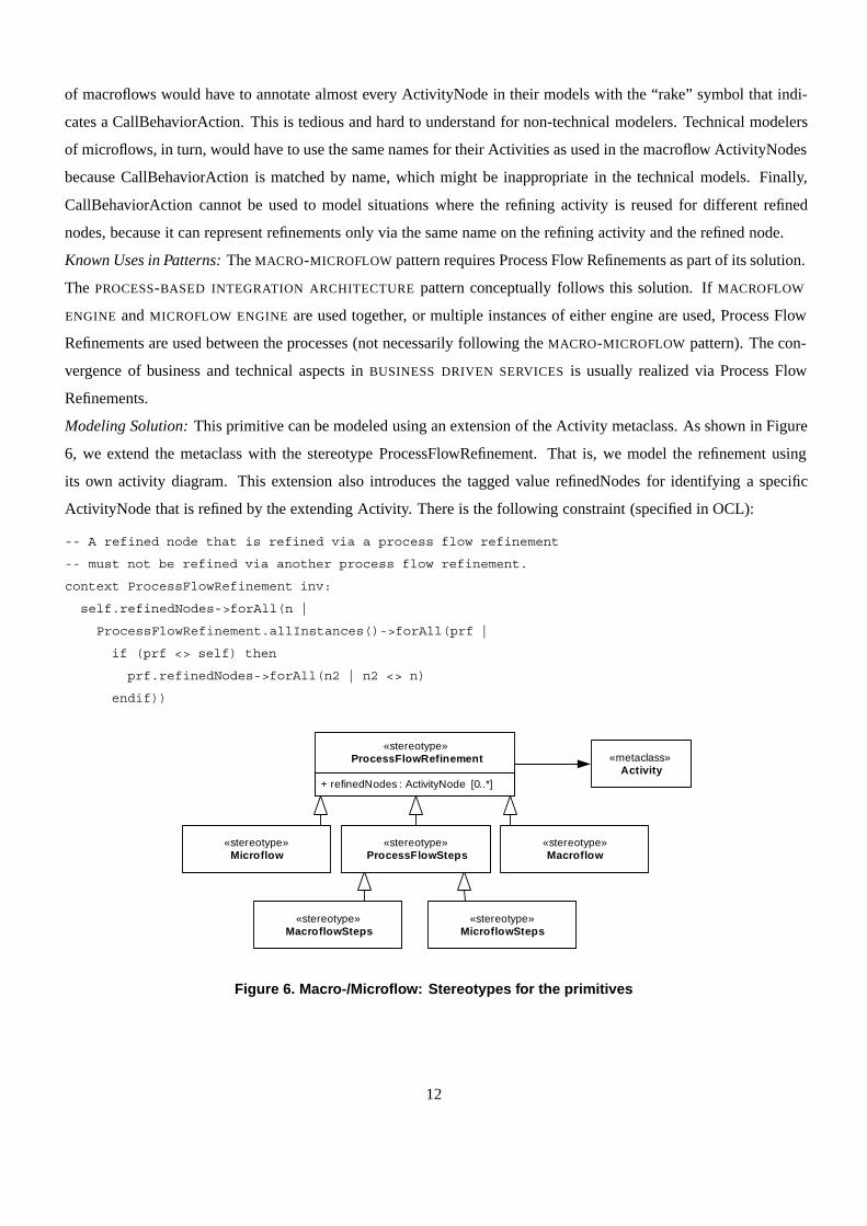
Modeling Solution: This primitive can be modeled using an extension of the Activity metaclass. As shown in Figure
6, we extend the metaclass with the stereotype ProcessFlowRefinement. That is, we model the refinement using
its own activity diagram. This extension also introduces the tagged value refinedNodes for identifying a specific
ActivityNode that is refined by the extending Activity. There is the following constraint (specified in OCL):
-- A refined node that is refined via a process flow refinement
-- must not be refined via another process flow refinement.
context ProcessFlowRefinement inv:
self.refinedNodes->forAll(n |
ProcessFlowRefinement.allInstances()->forAll(prf |
if (prf <> self) then
prf.refinedNodes->forAll(n2 | n2 <> n)
endif))
«stereotype»MacroflowSteps
«stereotype»MicroflowSteps
«metaclass»Activity
+ refinedNodes : ActivityNode [0..*]
«stereotype»ProcessFlowRefinement
«stereotype»ProcessFlowSteps
«stereotype»Macroflow
«stereotype»Microflow
Figure 6. Macro-/Microflow: Stereotypes for the primitives
12
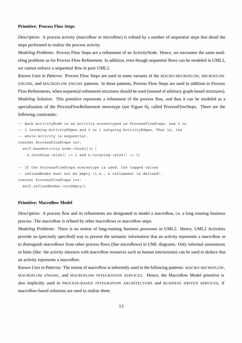
Primitive: Process Flow Steps
Description: A process activity (macroflow or microflow) is refined by a number of sequential steps that detail the
steps performed to realize the process activity.
Modeling Problems: Process Flow Steps are a refinement of an ActivityNode. Hence, we encounter the same mod-
eling problems as for Process Flow Refinement. In addition, even though sequential flows can be modeled in UML2,
we cannot enforce a sequential flow in pure UML2.
Known Uses in Patterns: Process Flow Steps are used in some variants of the MACRO-MICROFLOW, MICROFLOW
ENGINE, and MACROFLOW ENGINE patterns. In these patterns, Process Flow Steps are used in addition to Process
Flow Refinements, when sequential refinement structures should be used (instead of arbitrary graph-based structures).
Modeling Solution: This primitive represents a refinement of the process flow, and thus it can be modeled as a
specialization of the ProcessFlowRefinement stereotype (see Figure 6), called ProcessFlowSteps. There are the
following constraints:
-- Each ActivityNode in an Activity stereotyped as ProcessFlowSteps, has 0 or
-- 1 incoming ActivityEdges and 0 or 1 outgoing ActivityEdges. That is, the
-- whole Activity is sequential.
context ProcessFlowSteps inv:
self.baseActivity.node->forAll(n |
n.incoming->size() <= 1 and n.outgoing->size() <= 1)
-- If the ProcessFlowSteps stereotype is used, the tagged values
-- refinedNodes must not be empty (i.e., a refinement is defined).
context ProcessFlowSteps inv:
self.refinedNodes->notEmpty()
Primitive: Macroflow Model
Description: A process flow and its refinements are designated to model a macroflow, i.e. a long running business
process. The macroflow is refined by other macroflows or macroflow steps.
Modeling Problems: There is no notion of long-running business processes in UML2. Hence, UML2 Activities
provide no (precisely specified) way to present the semantic information that an activity represents a macroflow or
to distinguish macroflows from other process flows (like microflows) in UML diagrams. Only informal annotations
or hints (like: the activity interacts with macroflow resources such as human interactions) can be used to deduce that
an activity represents a macroflow.
Known Uses in Patterns: The notion of macroflow is inherently used in the following patterns: MACRO-MICROFLOW,
MACROFLOW ENGINE, and MACROFLOW INTEGRATION SERVICES. Hence, the Macroflow Model primitive is
also implicitly used in PROCESS-BASED INTEGRATION ARCHITECTURE and BUSINESS DRIVEN SERVICES, if
macroflow-based solutions are used to realize them.
13
Modeling Solution: This primitive can be modeled as an extension of the ProcessFlowRefinement stereotype (see
Figure 6), called Macroflow, for depicting macroflow process models. If the tagged value refinedNodes is not empty,
then the Macroflow is a refinement of another Macroflow. In addition, we model macroflow steps as a specialization
of the ProcessFlowSteps stereotype, called MacroflowSteps. There are the following constraints:
-- If a Macroflow Activity refines one of another Activity’s nodes, then
-- this other Activity must be itself stereotyped as Macroflow.
context Macroflow inv:
self.refinedNodes->forAll(rn |
Macroflow.allInstances()->exists(a | a.baseActivity = rn.activity))
-- Because MacroflowSteps inherit from ProcessFlowSteps, the tagged value
-- refinedNodes cannot be empty. In addition, the refined nodes must be
-- inside a Macroflow.
context MacroflowSteps inv:
self.refinedNodes->forAll(rn |
Macroflow.allInstances()->exists(a | a.baseActivity = rn.activity))
Primitive: Microflow Model
Description: A process flow and its refinements are designated to model a microflow, i.e., a short running technical
process.
Modeling Problems: Same as for macroflows, there is no notion of short running technical processes in UML2.
Hence, UML2 Activities provide no (precisely specified) way to represent a microflow or to distinguish them from
macroflows. Only informal annotations or hints (like: the activity interacts with microflow resources such as a
messaging system) can be used to deduce that an activity represents a microflow.
Known Uses in Patterns: The notion of microflow is inherently used in the following patterns: MACRO-MICROFLOW,
MICROFLOW ENGINE, and MICROFLOW EXECUTION SERVICES. Thus, Microflow Models are also implicitly used in
PROCESS-BASED INTEGRATION ARCHITECTURE and BUSINESS DRIVEN SERVICES, if microflow-based solutions
are used to realize them.
Modeling Solution: The Microflow Model is modeled analogous to the Macroflow Model primitive: Microflow is
introduced as an extension for the ProcessFlowRefinement stereotype and MicroflowSteps as an extension for the
ProcessFlowSteps stereotype (see Figure 6). There are also similar constraints as in Macroflow Model:
context Microflow inv:
self.refinedNodes->forAll(rn |
Microflow.allInstances()->exists(a | a.baseActivity = rn.activity))
context MicroflowSteps inv:
self.refinedNodes->forAll(rn |
Microflow.allInstances()->exists(a | a.baseActivity = rn.activity))
14
Primitive: Macro-Microflow Refinement
Description: Microflow Models are allowed to refine Macroflow Models.
Modeling Problems: This primitive connects the macroflow and microflow primitives, introduced before. Hence, all
the modeling problems introduced for macroflows and microflows so far, apply here as well.
Known Uses in Patterns: This primitive can be used in all patterns that interconnect macroflows and microflows.
That is, the MACRO-MICROFLOW describes a conceptual solution that uses this primitive, and many PROCESS-
BASED INTEGRATION ARCHITECTURES and BUSINESS DRIVEN SERVICES follow the primitive. The MACROFLOW
INTEGRATION SERVICE and MICROFLOW EXECUTION SERVICE patterns implement the glue between macroflows
and microflows and are thus used at those places in the models where this primitive is applied.
Modeling Solution: We can model this primitive by extending the Microflow Model primitive. In particular, if
refinedNodes of a Microflow is not empty, then the Microflow is a refinement of another Microflow or a Macroflow
or a MacroflowSteps activity. We also need to replace the first constraint of the Microflow Model primitive with the
following constraint:
-- If a Microflow activity refines another activity, then this other activity
-- must be itself stereotyped as Macroflow, MacroflowSteps, or Microflow.
context Microflow inv:
self.refinedNodes->forAll(rn |
Macroflow.allInstances()->exists(a | a.baseActivity = rn.activity) or
MacroflowSteps.allInstances()->exists(a | a.baseActivity = rn.activity) or
Microflow.allInstances()->exists(a | a.baseActivity = rn.activity))
4.3 Flow Automation Primitives
Primitive: Automated Macroflow Steps
Description: The Macroflow Steps are designed to run automatically, only with the resources that are accessible
inside of the process flow and without further interaction. Hence the Macroflow Steps are restricted to three kinds of
activity nodes: Invocations of process functions, access to process control data, and access to process resources.
Modeling Problems: There is no way to limit or restrict ordinary activity nodes at the model level to access only
specific resources or perform only specific actions. In standard UML subtypes of activity nodes can be defined to
depict the Automated Macroflow Steps as subclasses of the ActivityNode metaclass. But this requires a meta-model
extension, and we would need to additionally constrain the models.
Known Uses in Patterns: The three kinds of activity nodes to which Macroflow Steps get restricted to are those
elements that are typically provided within a MACROFLOW ENGINE. Hence Automated Macroflow Steps can run in
such an engine without having to access resources not offered by the engine. MACROFLOW INTEGRATION SERVICES
are typically realized in such a way that they can automatically run, when they are triggered by a macroflow activity.
This can be modeled via the Automated Macroflow Steps primitive. For the “invocations of process functions”
15

activity node type, there is an additional known use: If the service is not directly invoked, but a microflow is triggered,
then there is a one-to-one relationship to a MICROFLOW EXECUTION SERVICE.
Modeling Solution: This primitive can be modeled using three stereotypes for the ActivityNode metaclass: Invoke-
ProcessFunction, AccessControlDataItem, and AccessProcessResource. The AccessControlDataItem stereotype in-
troduces the key tagged value to identify the data item that is accessed. The AccessProcessResource stereotype
introduces the id tagged value to identify the particular resource that is accessed. The stereotype definitions are
shown in Figure 7. There is the following constraint:
-- All nodes of an activity stereotyped as MacroflowSteps are stereotyped either
-- as InvokeProcessFunction, AccessControlDataItem, or AccessProcessResource.
-- We need to exclude control nodes and object nodes from this constraint.
context MacroflowSteps inv:
self.baseActivity.node.forAll(n |
if (not self.oclIsKindOf(ControlNode) and not self.oclIsKindOf(ObjectNode)) then
InvokeProcessFunction.allInstances()->exists(n1 | n=n1.baseActivityNode) or
AccessControlDataItem.allInstances()->exists(n2 | n=n2.baseActivityNode) or
AccessProcessResource.allInstances()->exists(n3 | n=n3.baseActivityNode)
endif)
«stereotype»InvokeProcessFunction
«metaclass»ActivityNode
+ key : ProcessControlDataItem
«stereotype»AccessControlDataItem
+ id : ProcessResource
«stereotype»AccessProcessResource
Figure 7. Stereotypes for the Macroflow/Microflow Engine primitives
Primitive: Automated Microflow Steps
Description: The Microflow Steps are designed to run automatically; they are restricted to two kinds of activity
nodes which are relevant for microflows: Invocations of process functions and access to process control data. This
is similar to Automated Macroflow Steps, but the resources are omitted. This is because resources in macroflows are
either some virtual actor like an IT system acting in a certain role, or a human actor who interacts with an IT system,
and hence they are irrelevant for microflow models.
Modeling Problems: The modeling problem is identical to Automated Macroflow Steps.
16
Known Uses in Patterns: The two kinds of activity nodes to which Microflow Steps get restricted to are reflected by
the elements that are typically provided within a MICROFLOW ENGINE.
Modeling Solution: This primitive can be modeled using two stereotypes for the ActivityNode metaclass: Invoke-
ProcessFunction and AccessControlDataItem (see Figure 7). There is the following constraint:
-- All nodes of an activity stereotyped as MicroflowSteps are stereotyped
-- either as InvokeProcessFunction or AccessControlDataItem.
-- We need to exclude control nodes and object nodes from this constraint.
context MicroflowSteps inv:
self.baseActivity.node.forAll(n |
if (not self.oclIsKindOf(ControlNode) and not self.oclIsKindOf(ObjectNode)) then
InvokeProcessFunction.allInstances()->exists(n1 | n=n1.baseActivityNode) or
AccessControlDataItem.allInstances()->exists(n2 | n=n2.baseActivityNode)
endif)
«metaclass»ActivityNode
+ key : ProcessControlDataItem
«stereotype»AccessControlDataItem«stereotype»
InvokeProcessFunction
+ serviceName : String
«stereotype»ServiceInvocation
«stereotype»SyncServiceInvocation
+ invocationType : InvocationType
«stereotype»AsyncServiceInvocation
+ serviceName : String
«stereotype»ReadServiceData
«stereotype»FireAndForgetInvocation
«stereotype»OneReplyInvocation
«stereotype»MultipleReplyInvocation
+ serviceName : String
«stereotype»WriteServiceResult
«stereotype»ReadServiceDataFromControlData
+ value : Object
«stereotype»WriteServiceResultToControlData
«stereotype»ProcessControlDataDrivenInvocation
RequestReply
«enumeration»InvocationType
Correlation
«metaclass»AcceptEventAction
«stereotype»AsyncReplyEvent
correlation
correlation 0..*
1..*
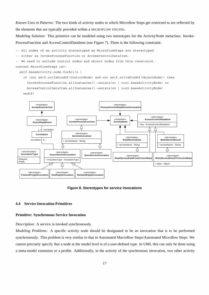
Figure 8. Stereotypes for service invocations
4.4 Service Invocation Primitives
Primitive: Synchronous Service Invocation
Description: A service is invoked synchronously.
Modeling Problems: A specific activity node should be designated to be an invocation that is to be performed
synchronously. This problem is very similar to that in Automated Macroflow Steps/Automated Microflow Steps: We
cannot precisely specify that a node at the model level is of a user-defined type. In UML this can only be done using
a meta-model extension or a profile. Additionally, in the activity of the synchronous invocation, two other activity
17
nodes must be present: one that gets the invocation data for the service and one that writes the service’s result. In
a synchronous invocation, both nodes are mandatory, if we assume that “void” invocation results are reported to the
client (as it is usual for synchronous invocations). Again, it is not possible to designate these nodes appropriately,
and also their mandatory presence cannot be enforced.
Known Uses in Patterns: All patterns in the pattern language have the notion of service invocations. Thus, this
primitive is useful for modeling a synchronous invocation scheme in any of these patterns.
Modeling Solution: This primitive can be modeled using the stereotype SyncServiceInvocation for the ActivityNode
metaclass (see Figure 8). The stereotype ReadServiceData for ActivityNode models that another activity must get
the invocation data for the service. The stereotype WriteServiceResult extends the ActivityNode to model that the
node writes the service’s result. There is the following constraint:
-- For the SyncServiceInvocation ActivityNode a ReadServiceData
-- node, as well as an WriteServiceResult node exist, both with the
-- same service name.
context SyncServiceInvocation inv:
self.baseActivityNode->forAll(ba |
ba.node->exists(n1 | ReadServiceData.allInstances()->exists(n2 |
n1 = n2.baseActivityNode and n2.serviceName = self.serviceName)) and
ba.node->exists(n1 | WriteServiceResult.allInstances()->exists(n2 |
n1 = n2.baseActivityNode and n2.serviceName = self.serviceName)))
Primitive: Asynchronous Service Invocation
Description: A service is invoked asynchronously.
Modeling Problems: The basic modeling problem is identical to Synchronous Service Invocation, we just require
a model of an asynchronous invocation. That is, in the activity of the invocation, one other activity nodes must
be present that gets the invocation data for the service. An asynchronous service invocation might have no result.
Hence, writing the service result is not mandatory. As in Synchronous Service Invocation the nodes cannot be
properly designated and the presence of mandatory elements cannot be enforced.
Known Uses in Patterns: This primitive is useful for modeling an asynchronous invocation scheme in any of the
patterns in the pattern language.
Modeling Solution: This primitive can be modeled using the stereotype AsyncServiceInvocation for the ActivityN-
ode metaclass. Also another activity must get the invocation data for the service. This can be modeled using another
stereotype ReadServiceData for ActivityNode (see Figure 8). All kinds of AsyncServiceInvocations can specify a
correlation, if a reply is expected. To model this, a generic interface Correlation is used, which typically contains a
request ID (or other information for idenitfying a request). These request IDs are used to correlate the asyncronous
replies to their requests (following the CORRELATION IDENTIFIER pattern [20]). For the purpose of dealing with
correlations, it is also necessary to distingusih asynchronous request and reply messages, which is done using the
18

InvocationType enumeration. The correlations are used in AsyncReplyEvents, which are used to receive the asy-
chronous replies, for correlating the requests and replies once a reply is received. There is the following constraint:
-- For the AsyncServiceInvocation ActivityNode an ReadServiceData
-- node with the same service name exists.
context AsyncServiceInvocation inv:
self.baseActivityNode->forAll(ba |
ba.node->exists(n1 | ReadServiceData.allInstances()->exists(n2 |
n1 = n2.baseActivityNode and n2.serviceName = self.serviceName)))
Primitive: Fire and Forget Invocation
Description: A service is invoked asynchronously with fire and forget semantics. That is, no result or acknowledg-
ment of the receipt of the invocation is expected.
Modeling Problems: The modeling problem is identical to Asynchronous Service Invocation, except that in Fire and
Forget Invocation it is mandatory that there is no results written for this service. The absence of a result writing
activity node for a specific invocation cannot be enforced in standard UML.
Known Uses in Patterns: This primitive is useful for modeling a fire and forget invocation scheme in any of the
patterns in the pattern language.
Modeling Solution: This primitive can be modeled using the stereotype FireAndForgetInvocation that specializes the
AsyncServiceInvocation stereotype. Additionally, there are the constraints that there are no results written for this
service and there is no correlation specified for the FireAndForgetInvocation.
-- For the FireAndForgetInvocation ActivityNode a corresponding
-- WriteServiceResult with the same service name does not exist.
context FireAndForgetInvocation inv:
self.baseActivityNode->forAll(ba |
not ba.node->exists(n1 | WriteServiceResult.allInstances()->exists(n2 |
n1 = n2.baseActivityNode and n2.serviceName = self.serviceName)))
-- A FireAndForgetInvocation has no correlation attached, as it receives no
-- result.
context FireAndForgetInvocation inv:
self.correlation->isEmpty()
Primitive: One Reply Asynchronous Invocation
Description: A service is invoked asynchronously, and exactly one result is coming back.
Modeling Problems: The modeling problem is identical to Asynchronous Service Invocation with the following
addition: For an asynchronous invocation we cannot guarantee that a result comes back in the same activity, as we
do not block for the result. For instance, in one Process Steps Refinement activity we can send the invocation, and
19

receive the result in another one. However, there must be one result for a OneReplyInvocation – maybe received in
some other activity. Again, this cannot be enforced in standard UML.
Known Uses in Patterns: This primitive is useful for modeling a one reply invocation scheme in any of the patterns
in the pattern language.
Modeling Solution: This primitive can be modeled using the stereotype OneReplyInvocation that specializes the
AsyncServiceInvocation stereotype, and an invariant that specifies that a service result must be written for the invo-
cation. The concern that exactly one reply is expected can be modeled by another invariant, which constrains the
OneReplyInvocation to require exactly one correlation object.
-- There is a WriteServiceResult ActivityNode for each OneReplyInvocation
-- service name.
context OneReplyInvocation inv:
WriteServiceResult.allInstances()->exists(n |
n.serviceName = self.serviceName)
-- There is exactly one correlation defined for a OneReplyInvocation.
context OneReplyInvocation inv:
self.correlation->size() = 1
Primitive: Multiple Reply Asynchronous Invocation
Description: A service is invoked asynchronously, and exactly one result is coming back.
Modeling Problems: The modeling problem is very similar to One Reply Asynchronous Invocation, but we must
model multiple possible result receptions, instead of only one. Again, this cannot be enforced in standard UML.
Known Uses in Patterns: This primitive is useful for modeling a multiple reply invocation scheme in any of the
patterns in the pattern language.
Modeling Solution: This primitive can be modeled using the stereotype MultipleReplyInvocation that specializes the
AsyncServiceInvocation stereotype, and an invariant that specifies that a service result must be written for the invo-
cation. The additional concern that multiple replies are expected are modeled by another invariant, which specifies
that a MultipleReplyInvocation requires one or more correlation objects.
-- There is a WriteServiceResult ActivityNode for each
-- MultipleReplyInvocation service name.
context MultipleReplyInvocation inv:
WriteServiceResult.allInstances()->exists(n |
n.serviceName = self.serviceName)
-- There are more than one correlations defined for a MultipleReplyInvocation.
context MultipleReplyInvocation inv:
self.correlation->size() > 1
20

Primitive: Process Control Data Driven Invocation
Description: A service is invoked from the process control data.
Modeling Problems: Process Control Data Driven Invocation is a special case of a Process Flow Refinement plus
one of the Service Invocation primitives. In addition, all data is read and written from/to the process control data.
Thus, for modeling this primitive the combination of the modeling problems from the Process Flow Refinement and
the service invocation primitives applies. In addition, data access must be restricted to the process control data. This,
again, cannot be modeled in standard UML.
Known Uses in Patterns: This primitive is primarily used to model the pattern MACROFLOW INTEGRATION SERVICE.
Often it is also used in the patterns where Automated Macroflow Steps/Automated Microflow Steps are used for
automatic activities: MACROFLOW ENGINE, MICROFLOW EXECUTION SERVICE, and MICROFLOW ENGINE.
Modeling Solution: This primitive can be modeled by depicting a service invocation in a refining activity, such as a
Process Flow Steps activity. The refined ActivityNode is stereotyped as ProcessControlDataDrivenInvocation. The
refining activity must contain a ServiceInvocation. There are two new stereotypes that specialize the AccessProcess-
ControlData stereotype: ReadServiceDataFromControlData, which also specializes ReadServiceData, and WriteSer-
viceResultToControlData, which also specializes WriteServiceResult. There is the following constraint:
-- A ProcessControlDataDrivenInvocation ActivityNode must be
-- refined by a ProcessFlowRefinement and in the refining Activity
-- there is (at least one) service invocation. In this Activity, all
-- ReadServiceData ActivityNodes are of type ReadServiceDataFromControlData,
-- and all WriteServiceResult ActivityNodes are of type
-- WriteServiceResultToControlData.
context ProcessControlDataDrivenInvocation inv:
ProcessFlowRefinement.allInstances()->exists(a |
a.refinedNodes->exists(rn |
rn = self.baseActivityNode
and
a.baseActivity.node->exists(s |
ServiceInvocation.allInstances()->exists(si |
si.baseActivityNode = s))
and
if ReadServiceData.allInstances()->exists(read |
read.baseActivityNode.activity = a.baseActivity)
then
read.oclIsKindOf(ReadServiceDataFromControlData)
endif
and
if WriteServiceResult.allInstances()->exists(write |
write.baseActivityNode.activity = a.baseActivity)
then
21
write.oclIsKindOf(WriteServiceResultToControlData)
endif))
5 Modeling patterns using the pattern primitives for process-oriented integration of services
In the previous section, we have already provided a mapping of the primitives to the known uses in process-
driven SOA patterns. The mapping of patterns to pattern primitives provides us with modeling constructs that can
be differently combined for different pattern instances and variants, but must conform to the pattern-to-primitive
mapping. That is, if a primitive is used in a model of a pattern instance, all precisely specified constraints of the
primitive must be fulfilled. Hence, the primitives precisely specify the proven practices documented in the patterns
as modeling constructs. In this section, we discuss how the four patterns, rendered in grey in Figure 3, can be modeled
using the pattern primitives introduced in the previous section.
Please note that we have intentionally applied the primitives both to the patterns and the concrete pattern variants
implemented in software systems from which the primitives have been identified. This is necessary because the
primitives represent condensed knowledge from multiple patterns and pattern known uses – in which the primitives
can be applied. Hence, it is necessary to demonstrate for each of these patterns and pattern known uses that the
primitive is a suitable modeling construct.
5.1 Modeling Macro-Microflow
The pattern MACRO-MICROFLOW works in the context that business processes shall be implemented using process
(workflow) technology. The pattern deals with the problem that models of business processes must be developed
considering the relationships and interdependencies to technical concerns.
The solution of the pattern is to structure a process model into two kinds of processes, macroflow and microflow.
The pattern strictly separates the macroflow from the microflow, and uses the microflow only for refinements of the
macroflow activities.
Both in macroflows and microflows we can observe refinements. The different kinds of refinement can be modeled
using the Process Flow Refinement primitive. Process Flow Refinement is a generic pattern primitive that can be used
for modeling all kinds of process refinements.
For the MACRO-MICROFLOW pattern it is mandatory, that the Macro-Microflow Refinement primitive is used, and
at least one Macroflow and one Microflow Model with a refinement relationship between them must be present in a
model. There are different specific kinds of refinement possible:
• Macroflows can be refined by other macroflows. That is, a Macroflow Model refines another Macroflow Model.
• Microflows can be refined by other microflows. That is, a Microflow Model refines another Microflow Model.
• Macroflows can be refined by microflows. That is, a Microflow Model refines another Macroflow Model.
22

«Macroflow»Model1
A
[true]
[false ]
C
«MacroflowSteps»Model2B{refinedNodes=B}
Y
OB
X
«Microflow»Model3X{refinedNodes=X}
[false ]
[true]
K
M
L
«MicroflowSteps»Model4L{refinedNodes=L}
F
E
Figure 9. Macro-Microflow modeling example 1
• Often it is additionally possible to refine each activity in a macroflow or microflow using a sequence of activity
steps. This can also be modeled using the Process Flow Steps primitive, either at the Macroflow Model or
Microflow Model level.
The Macro-Microflow Refinement primitives allow us to model a number of pattern variants of the MACRO-
MICROFLOW pattern. For instance, the MACRO-MICROFLOW structure may strictly follow a refinement in macroflow
→ macroflow steps → microflow → microflow steps. Figure 9 shows an example of such a refinement using the
UML2 representations of the pattern primitives.
Another, different exemplary structure is that the macroflows at the highest level depict the main business pro-
cesses, which are then refined by other macroflows depicting sub-processes that are still business-oriented. These
macroflows are refined stepwise via other macroflows. Finally, the macroflow activities of the lowest granularity
are refined by microflows. That is, in this second example, there are no process flow steps used in the model, but
multiple refinements at the macroflow level. Figure 10 shows an example of such a refinement using the UML2
representations of the pattern primitives.
Numerous other variants of the MACRO-MICROFLOW pattern are possible and can hence be modeled with the
primitives introduced in the previous section.
5.2 Modeling Macroflow Engine
The pattern MACROFLOW ENGINE works in the context that business processes need to adapt for instance due to
changed market conditions or business optimization initiatives. The pattern deals with the problem that it is necessary
to flexibly configure long-running business processes (macroflows) in a dynamic environment where business process
changes are regular practice, to reduce implementation time and effort of these business process changes.
The solution of the pattern is to apply the business process paradigm directly to architecture and application
design and development by extracting statically implemented business process logic from systems. These “macroflow
23

«Macroflow»MainBusinessProcessI
A
[true]
[false ]
C
«Macroflow»SubprocessB{refinedNodes=B}
Y
B
X
«Macroflow»BusinessProcessActivityZ{refinedNodes=Z}
[false ]
[true]
K
L
«MicroflowModel»ActivityL{refinedNodes=L}
E
Z
F
Figure 10. Macro-Microflow modeling example 2
aspects” of the business process definition and execution are delegated to a dedicated MACROFLOW ENGINE that
allows developers to configure business processes by flexibly orchestrating execution of macroflow activities and the
related business functions.
One pattern variant of MACROFLOW ENGINE is shown in Figure 11. Here, a MACROFLOW ENGINE is a component
that contains a dynamic number of macroflows, each consisting of a number of macroflow steps. The macroflow steps
are used to invoke business functions, interact with the process control data, and use resources.
Macroflow Engine Macroflow
+ add(in mf: Macroflow)+ remove(in macroflowID)+ execute(in macroflowID)
*1
- macroflowID
+ getID()
IT System exposes1..*1
Macroflow Control Data
Resource
Business Function
transforms
uses1..*1
1..*
1
Macroflow Step
has1..* 1
*
1
invokes
Figure 11. Design variant of Macroflow Engine
In the business process models, the MACROFLOW ENGINE is not represented by a specific component. But the
presence of the Macroflow Model and Macroflow Steps pattern primitives indicate that a MACROFLOW ENGINE
is used. An example for these primitives is already given in Figure 9. Whereas the Macroflow Model primitive
is mandatory in models using a MACROFLOW ENGINE, Macroflow Steps are optional in different variants because
24
process flow steps may be used for refining activities or not.
One typical pattern variant of MACROFLOW ENGINE is that a MACROFLOW ENGINE component contains a dy-
namic number of macroflows, each consisting of a number of macroflow steps. The macroflow steps are used to
invoke business functions, interact with the process control data, and use resources. This variant can be modeled
using the Automated Macroflow Steps primitive. That is, Macroflow Step models must only contain ActivityNodes
stereotyped either as InvokeProcessFunction, AccessControlDataItem, or AccessProcessResource. The use of the
Automated Macroflow Steps primitive is optional.
5.3 Modeling Microflow Engine
The pattern MICROFLOW ENGINE works in the context that technical IT integration processes need to be imple-
mented. The pattern deals with the problem that it is necessary to flexibly configure IT systems integration processes
in a dynamic environment, where IT process changes are regular practice, in order to reduce implementation time
and effort.
The solution of the pattern is to delegate the “microflow aspects” of the business process definition and execution
to a dedicated MICROFLOW ENGINE that allows one to configure microflows by flexibly orchestrating execution of
microflow activities and the related BUSINESS-DRIVEN SERVICES.
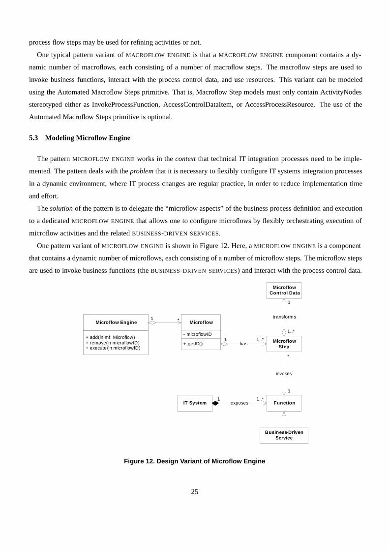
One pattern variant of MICROFLOW ENGINE is shown in Figure 12. Here, a MICROFLOW ENGINE is a component
that contains a dynamic number of microflows, each consisting of a number of microflow steps. The microflow steps
are used to invoke business functions (the BUSINESS-DRIVEN SERVICES) and interact with the process control data.
Microflow Engine Microflow
+ add(in mf: Microflow)+ remove(in microflowID)+ execute(in microflowID)
*1
- microflowID
+ getID()
IT System exposes1..*1
Microflow Control Data
Function
transforms
1..*1
1..*
1
Microflow Step
has
*
1
invokes
Business-Driven Service
Figure 12. Design Variant of Microflow Engine
25

In the business process models, the MICROFLOW ENGINE is depicted by the presence of the Microflow Model
and Microflow Steps pattern primitives. An examples for these primitives is already given in Figure 9. In addition,
the pattern can be characterized by its collaborators at the Microflow Steps level, which can be modeled using the
Automated Microflow Steps primitive.
As in MACROFLOW ENGINE, Microflow Model is mandatory for models of processes using a MICROFLOW EN-
GINE, whereas both Microflow Steps and Automated Microflow Steps are optional modeling primitives for this
pattern.
5.4 Modeling Macroflow Integration Service
The pattern MACROFLOW INTEGRATION SERVICE works in the context that macroflows represent long-running
business processes that are executed on a dedicated MACROFLOW ENGINE. Some activities in the macroflow models
represent automatic functions that must be executed by integrated systems. The pattern deals with the problem
that the functionality and implementation of process activities at the macroflow level should be decoupled from the
process logic that orchestrates them, in order to achieve flexibility, as far as the design and implementation of these
automatic functions is concerned.
The solution of the pattern is that automatic functions required by macroflow activities from external systems
are designed and exposed as dedicated MACROFLOW INTEGRATION SERVICES with well-defined service interfaces.
These services integrate external systems in a way that suits the functional requirements of the macroflow activity.
That is, they are designed to expose a specific business process’ view – needed by a macroflow – onto an exter-
nal system. The macroflow activity can thus be designed to contain only the functional business view and invoke
MACROFLOW INTEGRATION SERVICES for interaction with external systems.
One pattern variant of MACROFLOW INTEGRATION SERVICE is a MacroflowActivity that consists of the following
macroflow activity steps:
1. Data is read from the process control data
2. An external service is invoked using the data read
3. The result of the invocation is written to the process control data
In principle, we could use the stereotypes AccessControlDataItem and InvokeProcessFunction introduced in Fig-
ure 7 to model most variants of MACROFLOW INTEGRATION SERVICE. These stereotypes are very general, however.
For instance, the information that a service is invoked, how the service is invoked, and which control data accesses
belong to which service invocation gets lost. We have introduced a number of primitives that are relying on the
stereotypes derived from the two stereotypes above, which are all applicable in the context of the MACROFLOW
INTEGRATION SERVICE pattern.
26
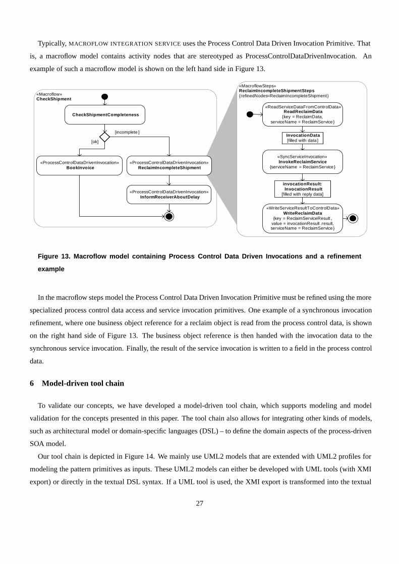
Typically, MACROFLOW INTEGRATION SERVICE uses the Process Control Data Driven Invocation Primitive. That
is, a macroflow model contains activity nodes that are stereotyped as ProcessControlDataDrivenInvocation. An
example of such a macroflow model is shown on the left hand side in Figure 13.
«Macroflow»CheckShipment
«ProcessControlDataDrivenInvocation»InformReceiverAboutDelay
CheckShipmentCompleteness
«ProcessControlDataDrivenInvocation»BookInvoice
[ok]
[incomplete ]
«ProcessControlDataDrivenInvocation»ReclaimIncompleteShipment
«MacroflowSteps»ReclaimIncompleteShipmentSteps{refinedNodes=ReclaimIncompleteShipment}
«ReadServiceDataFromControlData»ReadReclaimData
{key = ReclaimData, serviceName = ReclaimService}
«SyncServiceInvocation»InvokeReclaimService
{serviceName = ReclaimService }
InvocationData[filled with data ]
invocationResult : InvocationResult
[filled with reply data]
«WriteServiceResultToControlData»WriteReclaimData
{key = ReclaimServiceResult ,value = invocationResult .result,serviceName = ReclaimService}
Figure 13. Macroflow model containing Process Control Data Driven Invocations and a refinement
example
In the macroflow steps model the Process Control Data Driven Invocation Primitive must be refined using the more
specialized process control data access and service invocation primitives. One example of a synchronous invocation
refinement, where one business object reference for a reclaim object is read from the process control data, is shown
on the right hand side of Figure 13. The business object reference is then handed with the invocation data to the
synchronous service invocation. Finally, the result of the service invocation is written to a field in the process control
data.
6 Model-driven tool chain
To validate our concepts, we have developed a model-driven tool chain, which supports modeling and model
validation for the concepts presented in this paper. The tool chain also allows for integrating other kinds of models,
such as architectural model or domain-specific languages (DSL) – to define the domain aspects of the process-driven
SOA model.
Our tool chain is depicted in Figure 14. We mainly use UML2 models that are extended with UML2 profiles for
modeling the pattern primitives as inputs. These UML2 models can either be developed with UML tools (with XMI
export) or directly in the textual DSL syntax. If a UML tool is used, the XMI export is transformed into the textual
27

DSL syntax. That is, internally all inputs are transformed into the same DSL syntax.
Frag [44, 43] is a tailorable language, specifically designed for the task for defining DSLs. We use Frag as the
syntactic foundation of the textual DSLs and for defining the meta-models of the DSLs. Among other things, Frag
supports the tailoring of its object system and the extension with new language elements. Hence, Frag provides a
good basis for defining a UML2-based textual DSL because it is easy to tailor Frag to support the definition of the
UML meta-classes. Frag automatically provides us with a syntax for defining application models using the UML2
meta-classes. In addition to UML2 meta-models, we have defined a constraint language which follows the OCL’s
constructs.
The model validator gets all input models and validates the conformance of the application models to the meta-
models. It also checks all OCL constraints. Especially, that means it checks the constraints given by the pattern
primitive definitions. After the model is validated it is transformed into an EMF (Eclipse Modeling Framework)
model, which is understood by the code generator. We then generate code in executable languages, such as Java and
BPEL, using the code generator.
UML2 Activity Diagrams: Process Flow
UML2 Activity Diagrams: Message Flow
UML2 Component Diagrams: Architecture
UML2 Class/Object Diagrams: Business Objects
Frag UML2 Meta-Model
Individual Code
Frag Syntax-Based DSLs
Frag UML2 Profile:SOA Pattern Primitives
XMI2Frag Transformation Plugin
Frag2EMFTransformation Plugin
Frag Model Validator
Code Generator
Transformation Rules/Templates
System Code
Figure 14. Tool chain overview
To illustrate how the primitive models are transformed, let us consider the Process Flow Steps primitive as an
example. To model this primitive, we first must introduce UML2 stereotypes to distinguish the different kinds of
refined/refinement activities (see Figure 6) in the UML2 models. The same extension for the Activity meta-class
looks as follows in the Frag textual syntax:
MMM::Stereotype create SOAPrimitives::ProcessFlowRefinement \
-extends UML2::Activity \
28
-attributes {
refinedNodes UML2::ActivityNode
}
MMM::Stereotype create SOAPrimitives::Microflow \
-superclasses SOAPrimitives::ProcessFlowRefinement
MMM::Stereotype create SOAPrimitives::Macroflow \
-superclasses SOAPrimitives::ProcessFlowRefinement
MMM::Stereotype create SOAPrimitives::ProcessFlowSteps \
-superclasses SOAPrimitives::ProcessFlowRefinement
MMM::Stereotype create SOAPrimitives::MicroflowSteps \
-superclasses SOAPrimitives::ProcessFlowSteps
MMM::Stereotype create SOAPrimitives::MacroflowSteps \
-superclasses SOAPrimitives::ProcessFlowSteps
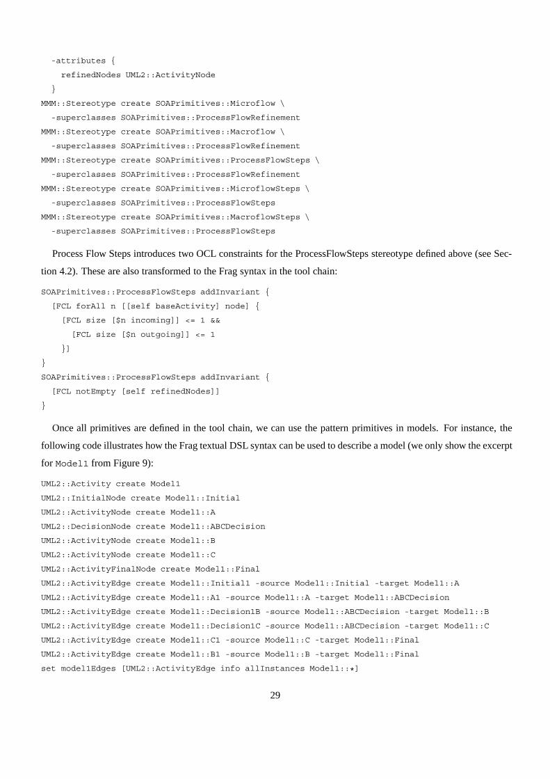
Process Flow Steps introduces two OCL constraints for the ProcessFlowSteps stereotype defined above (see Sec-
tion 4.2). These are also transformed to the Frag syntax in the tool chain:
SOAPrimitives::ProcessFlowSteps addInvariant {
[FCL forAll n [[self baseActivity] node] {
[FCL size [$n incoming]] <= 1 &&
[FCL size [$n outgoing]] <= 1
}]
}
SOAPrimitives::ProcessFlowSteps addInvariant {
[FCL notEmpty [self refinedNodes]]
}
Once all primitives are defined in the tool chain, we can use the pattern primitives in models. For instance, the
following code illustrates how the Frag textual DSL syntax can be used to describe a model (we only show the excerpt
for Model1 from Figure 9):
UML2::Activity create Model1
UML2::InitialNode create Model1::Initial
UML2::ActivityNode create Model1::A
UML2::DecisionNode create Model1::ABCDecision
UML2::ActivityNode create Model1::B
UML2::ActivityNode create Model1::C
UML2::ActivityFinalNode create Model1::Final
UML2::ActivityEdge create Model1::Initial1 -source Model1::Initial -target Model1::A
UML2::ActivityEdge create Model1::A1 -source Model1::A -target Model1::ABCDecision
UML2::ActivityEdge create Model1::Decision1B -source Model1::ABCDecision -target Model1::B
UML2::ActivityEdge create Model1::Decision1C -source Model1::ABCDecision -target Model1::C
UML2::ActivityEdge create Model1::C1 -source Model1::C -target Model1::Final
UML2::ActivityEdge create Model1::B1 -source Model1::B -target Model1::Final
set model1Edges [UML2::ActivityEdge info allInstances Model1::*]
29
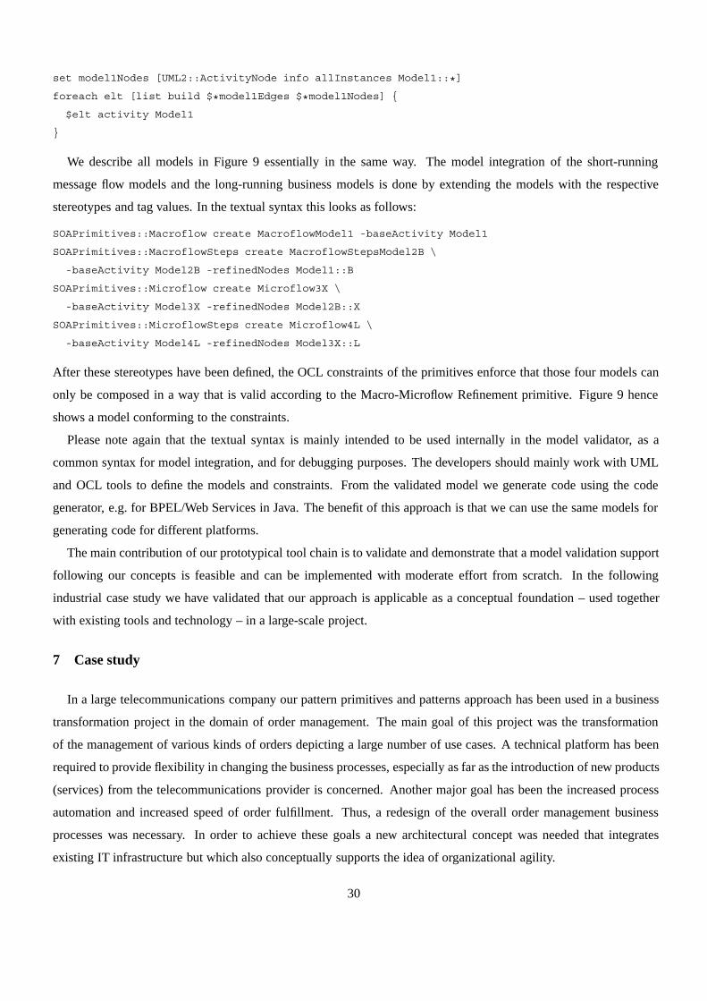
set model1Nodes [UML2::ActivityNode info allInstances Model1::*]
foreach elt [list build $*model1Edges $*model1Nodes] {
$elt activity Model1
}
We describe all models in Figure 9 essentially in the same way. The model integration of the short-running
message flow models and the long-running business models is done by extending the models with the respective
stereotypes and tag values. In the textual syntax this looks as follows:
SOAPrimitives::Macroflow create MacroflowModel1 -baseActivity Model1
SOAPrimitives::MacroflowSteps create MacroflowStepsModel2B \
-baseActivity Model2B -refinedNodes Model1::B
SOAPrimitives::Microflow create Microflow3X \
-baseActivity Model3X -refinedNodes Model2B::X
SOAPrimitives::MicroflowSteps create Microflow4L \
-baseActivity Model4L -refinedNodes Model3X::L
After these stereotypes have been defined, the OCL constraints of the primitives enforce that those four models can
only be composed in a way that is valid according to the Macro-Microflow Refinement primitive. Figure 9 hence
shows a model conforming to the constraints.
Please note again that the textual syntax is mainly intended to be used internally in the model validator, as a
common syntax for model integration, and for debugging purposes. The developers should mainly work with UML
and OCL tools to define the models and constraints. From the validated model we generate code using the code
generator, e.g. for BPEL/Web Services in Java. The benefit of this approach is that we can use the same models for
generating code for different platforms.
The main contribution of our prototypical tool chain is to validate and demonstrate that a model validation support
following our concepts is feasible and can be implemented with moderate effort from scratch. In the following
industrial case study we have validated that our approach is applicable as a conceptual foundation – used together
with existing tools and technology – in a large-scale project.
7 Case study
In a large telecommunications company our pattern primitives and patterns approach has been used in a business
transformation project in the domain of order management. The main goal of this project was the transformation
of the management of various kinds of orders depicting a large number of use cases. A technical platform has been
required to provide flexibility in changing the business processes, especially as far as the introduction of new products
(services) from the telecommunications provider is concerned. Another major goal has been the increased process
automation and increased speed of order fulfillment. Thus, a redesign of the overall order management business
processes was necessary. In order to achieve these goals a new architectural concept was needed that integrates
existing IT infrastructure but which also conceptually supports the idea of organizational agility.
30

As a result of the demand of an architectural paradigm that supports organizational agility while integrating the
existing IT systems and infrastructure and thus saving investments, a process-driven SOA approach has been chosen.
The main general architectural pattern was the ENTERPRISE SERVICE BUS [25, 46]. This pattern unifies the access
to applications and backends using services and service adapters, by using message-oriented, event-driven commu-
nication between these services to enable flexible integration. The integration of the process-driven approach with
SOA has been solved by applying the PROCESS-BASED INTEGRATION ARCHITECTURE pattern (see Section 3.2).
The technology used for implementing the service bus has been IBM WebSphere Message Broker [21] with
WebSphere MQ [22] as the main messaging platform. Consequently, the message broker has been used to implement
the microflow level.
As far as the macroflow level is concerned, two technologies have been used that serve two different purposes.
WebSphere MQ Workflow [23] has been used to depict the main business processes for managing all orders. The
business processes related to technical activation issues have been implemented with OMS Metasolv [33] (now
acquired by Oracle). This product is well established in the telecommunications industry and includes some off-the-
shelf features that make it suitable for this specific domain. This mainly covers very technical parts of the fulfillment
process, e.g. technically activating a new ISDN/DSL account. To provide flexibility for the business logic concerning
the configuration of rules for products and services the Selectica rule engine [36] has been used. Various existing IT
systems being necessary for processing the orders have been integrated via the service bus, e.g. an existing customer
management system. An architectural overview is given in Figure 15.
Reporting
Service Bus
Fulfillment
PersonsContactHistory
Partner-mngmt
Communi-cation
Order EntryOrder
ClearingMQSeriesWorkflow
Order Types
WBI Message Broker
MQSeries
System A DTAG-Sst.
System B HW-SAP
System C System D
System E
Order Management
Order Tracking
Report Generation
Online-Monitoring
System Management
Orders and Fulfillment History
Metasolv OMS
TechnicalCapture
TechnicalFulfillment
Metasolv Log
TechnicalClearing
Service Bus
WBI Message Broker
MQSeries
Generic InterfaceCustomer & Product
Management
ProductCatalog
Customerand Contract
DataInterface
Order Capture
ProductRules
Central Capture
CaptureAdapter
LeadMgmt.
Customer Selfcare
Selectica
OnlineGUI
SiebelSales
Figure 15. Enterprise Service Bus architecture for a telecommunications provider
31

At the time when the project commenced, the customer had already modeled business processes with Visio rep-
resenting the purely business related view without considering the architectural concept. Thus, these processes have
not followed the concepts of service-orientation and also did not consider aspects of flexibility and configurability
of the process architecture. A gap analysis has pointed out many major issues with these business processes, which
resulted in the decision that the processes could not be implemented on this architecture as they fail the major design
guideline to provide flexibility. The major issues being detected in this gap analysis can be named as follows:
1. Inconsistent process hierarchy: The business processes structures in terms of a deterministic behavior of call-
ing sub-processes have not been modeled appropriately.
2. Missing structure concerning detailed modeling: The processes have varied widely in considering business
and technical details. These two concerns have not been separated and modeled accurately in encapsulated
processes.
3. Inconsistent interfaces when calling sub-processes: The business data being passed between processes as well
as the generated and captured events from the processes did not match.
4. Error prone flow logic: Many processes have been designed as huge constructs, where only a subset of all
possible events and cases have been considered.
5. No synchronization with business object model: The processes did not consider an underlying business object
model, such that it has not been clear what objects have been processed in these processes and whether the
structures of the processes match a business object model.
6. No synchronization issues considered: Many processes run in parallel and events may be generated from
parallel processes that influence the behavior of a running process, e.g. the cancellation of a currently processed
order. These events have not been considered in the models.
7. Redundancy: Many processes showed redundant structures, which contradicts the concept of encapsulation to
reduce effort and increase flexibility.
All these issues pointed out that the business processes did not match the customer’s intended business goals. A
sound meta-model was required to resolve these issues and to provide a process model that suits the SOA approach
and the business goals.
The pattern primitives allowed us to develop detailed process models within a component-oriented process archi-
tecture concept. The pattern primitive UML2 extensions have been used to model the macroflows and microflows.
Also the microflows in GUIs have been modeled that way. The primitives thus allowed us to precisely specify and
integrate the knowledge gained from the patterns in the models following a consistent modeling style. Figure 16
shows the high-level process architecture for order management. The process architecture is represented as a set of
process components that stand as independent but interacting units. The Order Management process itself and its
32
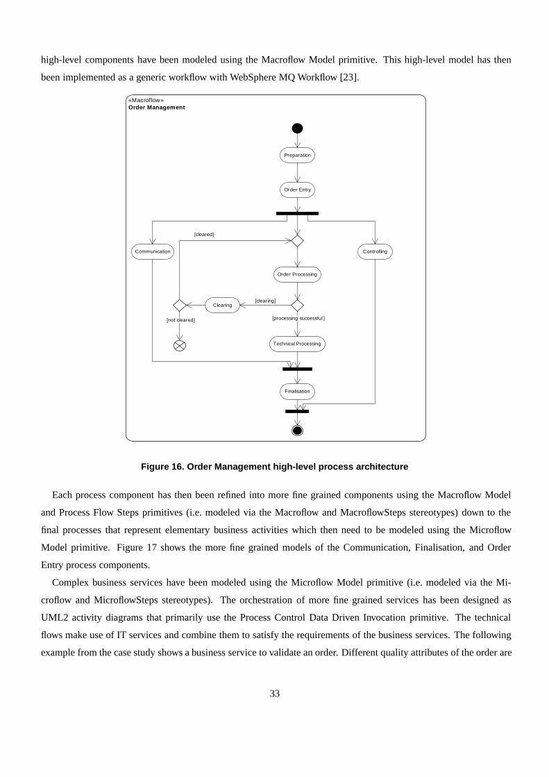
high-level components have been modeled using the Macroflow Model primitive. This high-level model has then
been implemented as a generic workflow with WebSphere MQ Workflow [23].
«Macroflow»Order Management
Preparation
Order Entry
Order Processing
Clearing
ControllingCommunication
[clearing]
Technical Processing
[cleared]
[processing successful ]
Finalisation
[not cleared]
Figure 16. Order Management high-level process architecture
Each process component has then been refined into more fine grained components using the Macroflow Model
and Process Flow Steps primitives (i.e. modeled via the Macroflow and MacroflowSteps stereotypes) down to the
final processes that represent elementary business activities which then need to be modeled using the Microflow
Model primitive. Figure 17 shows the more fine grained models of the Communication, Finalisation, and Order
Entry process components.
Complex business services have been modeled using the Microflow Model primitive (i.e. modeled via the Mi-
croflow and MicroflowSteps stereotypes). The orchestration of more fine grained services has been designed as
UML2 activity diagrams that primarily use the Process Control Data Driven Invocation primitive. The technical
flows make use of IT services and combine them to satisfy the requirements of the business services. The following
example from the case study shows a business service to validate an order. Different quality attributes of the order are
33
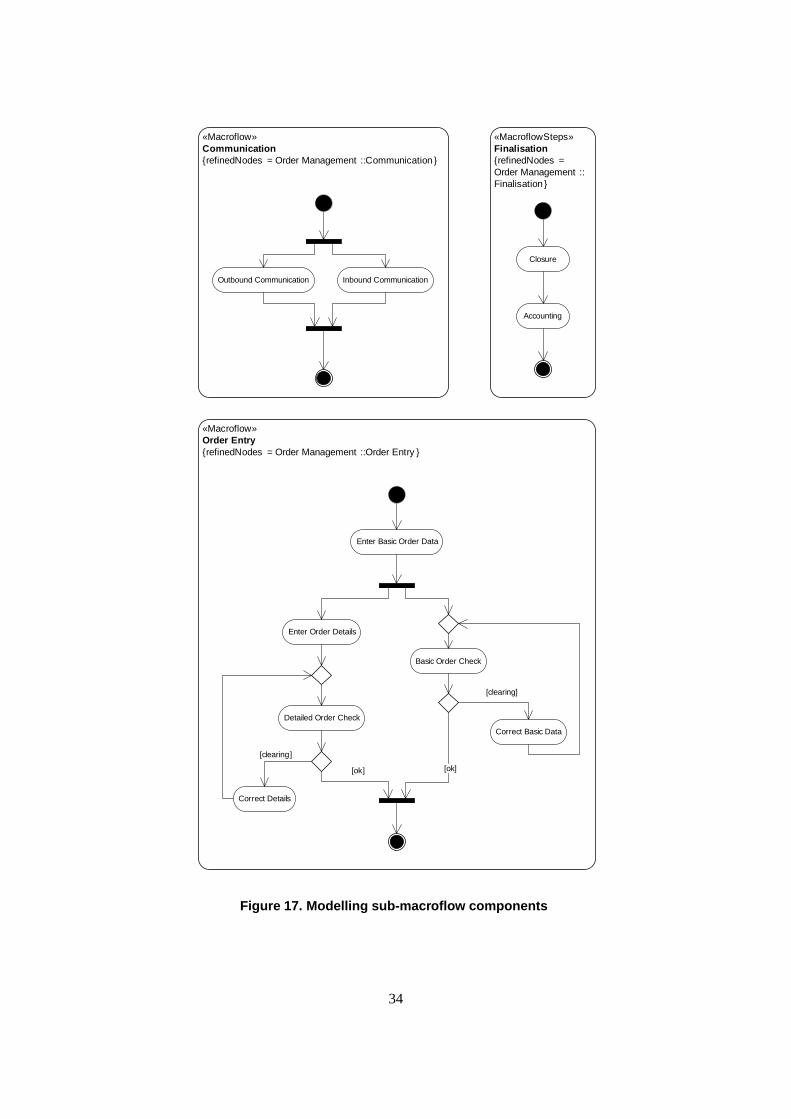
«Macroflow»Communication{refinedNodes = Order Management ::Communication }
Inbound CommunicationOutbound Communication
«MacroflowSteps»Finalisation{refinedNodes = Order Management ::Finalisation }
Closure
Accounting
«Macroflow»Order Entry{refinedNodes = Order Management ::Order Entry }
Enter Basic Order Data
Basic Order Check
Enter Order Details
Correct Basic Data
[clearing]
Detailed Order Check
Correct Details
[clearing]
[ok] [ok]
Figure 17. Modelling sub-macroflow components
34
checked via a set of fine grained services that are executed in a sequence. Figure 18 presents a Basic Order Checking
service modeled as a microflow.
At the lowest level of microflow decomposition where actual services of backend applications needed to be in-
voked, the stereotypes for reading and writing process control data, as well as the stereotypes for different types of
invocations have been used to realize the Process Control Data Driven Invocation primitive. This allowed a quite de-
tailed specification at this level. The diagram in Figure 19 shows the detailed model of the Check Customer Financial
Status business service.
This business service, which already appeared in an orchestration flow in Figure 18, has thus been specified in
detail. The detailed specification uses the ReadServiceDataFromControlData, OneReplyInvocation, and WriteSer-
viceResultToControlData stereotypes. The service consists of an asynchronous request for the financial status of a
customer. The actual financial status information is captured in a second service call that operates with the request ID
provided by the first call. That means, although the very detailed technical services operate asynchronously, the busi-
ness service Check Customer Financial Status simulates synchronous behavior by encapsulating the asynchronous
request and reply. In this case the request is actually satisfied by an external organization, i.e. the request and reply
services are services of an external business partner.
These examples from the case show that the services could be designed during process modeling with the help of
the primitives considering existing IT system functionality and thus providing a convergent top-down business pro-
cess driven (following business goals) and bottom-up IT system driven modeling approach (considering feasibility),
according to the BUSINESS-DRIVEN SERVICE pattern (see Section 3.2).
As a result, the primitives significantly helped resolving the mentioned problems with the business process models
by introducing clear conceptual structures that address these issues at the core. This way the mentioned problems
could be avoided introducing an appropriate modeling style represented by the primitives.
Prior to starting process modeling activities, a business object model underlying the business processes has been
designed to represent the structure of orders. As a result, the redesigned business processes did not just relate to the
mentioned process architecture concept but have also been based on a specified business object model. Following that
approach it could clearly be modeled which objects are subject of activities in processes and which attributes need to
be passed to services, as illustrated in Figure 19. A few iterations have been necessary to balance the requirements
from the services with the business objects model, such that all parameters demanded by the services were available
in the business objects.
8 Related work and evaluation
In Section 2, we have identified five major problems to be addressed by our approach. Before we compare our
approach to related work, let us briefly summarize how we have solved each of these problems:
1. We have addressed the problem that there is no technology-neutral modeling approach for process-driven SOAs
by developing and validating a novel approach to model process-driven SOAs following proven practices –
35

«Microflow»Basic Order Checking{refinedNodes = Order Entry ::Basic Order Check}
«ProcessControlDataDrivenInvocation»Check Order Already Exists
«ProcessControlDataDrivenInvocation»Check Customer Financial Status
«ProcessControlDataDrivenInvocation»Check Customer Data
«ProcessControlDataDrivenInvocation»Check Blacklist
[ok]
[ok]
[ok]
[ok]
[clearing]
[clearing]
[clearing]
[clearing]
Figure 18. Modelling microflows with business service orchestration
36

«Microflow»Check Customer Financial Status{refinedNodes = Basic Order Checking::Check Customer Financial Status}
«ReadServiceDataFromControlData»Read Customer Financial Data
{key = financialData,serviceName = FinancialStatusRequest}
«OneReplyInvocation»Invoke FinancialServiceRequest Service{serviceName = FinancialStatusRequest ,
invocationType = Request}
InvocationData[filled with data ]
«WriteServiceResultToControlData»Write Financial Status Request Result
{key = requestID,value = invocationResult .result,
serviceName = FinancialStatusRequest }
CustomerData
invocationResult : InvocationResult
[filled with reply data ]
«AsyncReplyEvent»FinancialServiceRequest
Service Reply
Correlation
[clearing ]
[ok]
«ReadServiceDataFromControlData»Read Financial Status Request ID
{key = requestID,serviceName = FinancialStatusResult }
«OneReplyInvocation»Invoke FinancialStatusResult Service{serviceName = FinancialStatusResult ,
invocationType = Request}
InvocationData[filled with data]
«WriteServiceResultToControlData»Write FinancialStatusResult Result
{key = financialStatusInfo ,value = invocationResult .result,
serviceName = FinancialStatusResult }
invocationResult : InvocationResult
[filled with reply data]
«AsyncReplyEvent»FinancialServiceResult
Service Reply
Correlation
[clearing ]
[ok]
Fill Process Control Data with Customer Data
CheckStatusProcessControlData[contains service invocation data ]
CheckStatusProcessControlData[contains service invocation and
financial data ]
CheckStatusProcessControlData[contains service invocation , financial
data, and requestID]
Figure 19. Modelling low level microflows with detailed data input and output specifications
37

described by software patterns.
2. We have addressed the problem that these patterns are only described informally by introducing an interme-
diary, precisely specified concept, called pattern primitives, which can be used to model process-driven SOAs
according to the proven practices.
3. We have addressed the problem that process-driven SOA models are hard to understand and be kept consistent
by introducing one central (precisely specified) flow abstraction model that interconnects the various (precisely
specified) models and is based on the pattern primitives concept.
4. We have addressed the problem that design decisions in SOA models are hard to trace and can get violated
during later evolution by modeling pattern-based design decisions explicitly following the pattern primitives
concept and introducing precisely specified constraints in the models so that the patterns’ inherent properties
cannot accidentally get violated.
5. We have addressed the problem that model-driven development of process-driven SOAs is not yet well sup-
ported by developing such a modeling approach and a tool suite that validates the capabilities of the approach
for model-driven development.
To the best of our knowledge, no other scientific or practical approach solves the research problems addressed by
this paper in their entirety. In the remainder of this section, we will compare our approach to the relevant related
work, on which it is based.
There are a number of related approaches regarding the documentation of SOA best practices. For instance,
a number of reference architectures and blueprints have been proposed [39, 6, 40]. Other authors provide specific
surveys of composition methods in the area of Web services, such as methods for automated Web service composition
[34], or technologies to perform service composition and composition strategies [11]. All these approaches focus,
however, on specific technologies or composition techniques. Hence, in first place, they explain implementation
techniques or generic models. They do not – like our approach – focus on a detailed modeling concept that is
universally applicable.
Zimmermann et al. present a generic modeling approach for SOA projects [47]. Like our approach, the approach is
based on project experiences and distills proven practices from practical cases. The approach also integrates multiple
kinds of models for a SOA: object-oriented analysis and design, enterprise architecture, and business processes.
Even though there are many similarities to our approach, there is the difference that the authors use rather informal
models to illustrate their approach, and do not provide a concept for explaining the conceptual building blocks of the
architecture (like the patterns in our approach).
Erl presents a service analysis approach [13], specifically focusing on pragmatic advice for strategic decisions
about integration issues. Erl covers both technical and design issues, as well as strategic planning. Akin to the patterns
in our work, many best practices are introduced, but in contrast to our patterns, Erl’s best practices focus on specific
38
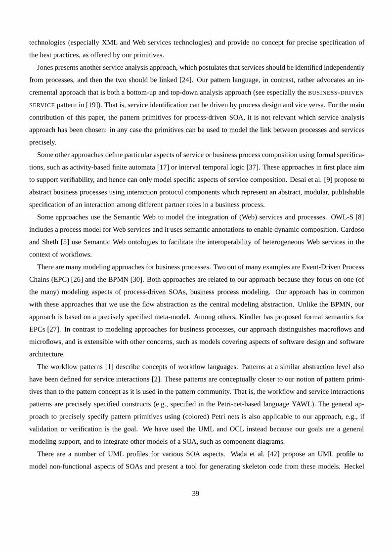
technologies (especially XML and Web services technologies) and provide no concept for precise specification of
the best practices, as offered by our primitives.
Jones presents another service analysis approach, which postulates that services should be identified independently
from processes, and then the two should be linked [24]. Our pattern language, in contrast, rather advocates an in-
cremental approach that is both a bottom-up and top-down analysis approach (see especially the BUSINESS-DRIVEN
SERVICE pattern in [19]). That is, service identification can be driven by process design and vice versa. For the main
contribution of this paper, the pattern primitives for process-driven SOA, it is not relevant which service analysis
approach has been chosen: in any case the primitives can be used to model the link between processes and services
precisely.
Some other approaches define particular aspects of service or business process composition using formal specifica-
tions, such as activity-based finite automata [17] or interval temporal logic [37]. These approaches in first place aim
to support verifiability, and hence can only model specific aspects of service composition. Desai et al. [9] propose to
abstract business processes using interaction protocol components which represent an abstract, modular, publishable
specification of an interaction among different partner roles in a business process.
Some approaches use the Semantic Web to model the integration of (Web) services and processes. OWL-S [8]
includes a process model for Web services and it uses semantic annotations to enable dynamic composition. Cardoso
and Sheth [5] use Semantic Web ontologies to facilitate the interoperability of heterogeneous Web services in the
context of workflows.
There are many modeling approaches for business processes. Two out of many examples are Event-Driven Process
Chains (EPC) [26] and the BPMN [30]. Both approaches are related to our approach because they focus on one (of
the many) modeling aspects of process-driven SOAs, business process modeling. Our approach has in common
with these approaches that we use the flow abstraction as the central modeling abstraction. Unlike the BPMN, our
approach is based on a precisely specified meta-model. Among others, Kindler has proposed formal semantics for
EPCs [27]. In contrast to modeling approaches for business processes, our approach distinguishes macroflows and
microflows, and is extensible with other concerns, such as models covering aspects of software design and software
architecture.
The workflow patterns [1] describe concepts of workflow languages. Patterns at a similar abstraction level also
have been defined for service interactions [2]. These patterns are conceptually closer to our notion of pattern primi-
tives than to the pattern concept as it is used in the pattern community. That is, the workflow and service interactions
patterns are precisely specified constructs (e.g., specified in the Petri-net-based language YAWL). The general ap-
proach to precisely specify pattern primitives using (colored) Petri nets is also applicable to our approach, e.g., if
validation or verification is the goal. We have used the UML and OCL instead because our goals are a general
modeling support, and to integrate other models of a SOA, such as component diagrams.
There are a number of UML profiles for various SOA aspects. Wada et al. [42] propose an UML profile to
model non-functional aspects of SOAs and present a tool for generating skeleton code from these models. Heckel
39

et al. [18] propose a UML profile for dynamic service discovery in a SOA by providing stereotypes that specify
the relationships among service implementations, service interfaces, and requirements. Gardner et al. [16] define
a UML profile to specify service orchestration with the goal to map the specification to BPEL code. Even though
these approaches focus on different application areas of a SOA, they share similar characteristics: In contrast to our
approach, the modeling constructs in these approaches are not systematically derived from proven practices. Hence,
the approaches are very specific for the application area they focus on.
There are also a number of related approaches for the formalization or precise specification of patterns [12, 29, 38,
28]. These approaches mainly describe simple single patterns from [15] in a precise manner. But there are a number
of issues with these approaches: First, these approaches in first place do only specify a specific implementation
variant of these patterns, not all possible variants. That is, they are too limited in the abstractions they propose
to grasp the rich concepts found in patterns, and do not do not deal with the inherent variability found in pattern
descriptions. Secondly, they do not provide a concept for dealing with the central concept of pattern languages which
explain the relationships of different pattern-based design decisions in terms of sequences. We have resolved these
problems using the pattern primitive concept and applied our primitives to a pattern language that is (much) more
complex than single patterns from [15].
Table 2 summarizes the evaluation of our work in comparison to the related work.
9 Conclusion
We have presented a pattern language that represents proven practices in the area of process-oriented integration of
services. A central, conceptual problem of this pattern language is that there is no modeling support for finding and
representing the patterns in process models. Hence, when the patterns are applied, as the software designs evolve,
the design knowledge and rationale might get lost or the patterns’ constraints might get violated.
To remedy this problem, we have proposed a modeling approach for precisely specifying process-driven SOAs
based on the concept of pattern primitives. The primitives are represented in the various flow models of a process-
driven SOA. We have elicited a catalog of 13 primitives, and precisely specified them using an UML2 profile for
activity diagrams and OCL. The approach is very general and can easily be used with other process modeling ap-
proaches, if precise specification of constraints and meta-model extensions are possible. We have also mapped the
pattern primitives to the patterns in the pattern language for process-oriented integration of services.
We have validated our approach by developing a model-driven tool chain to support the generation of models in
other languages (such as BPEL or source code) and the validation of process-driven SOA models. We have also
applied our approach in case studies for further validation (an industrial case study is discussed in Section 7).
As future work, we plan to develop further tool support and integrate more model types. We want to extend UML
tools with visual stereotypes (or meta-model extensions) which are more visually appealing than textual stereotypes.
Also, we want to develop more plug-ins for code generation.
40
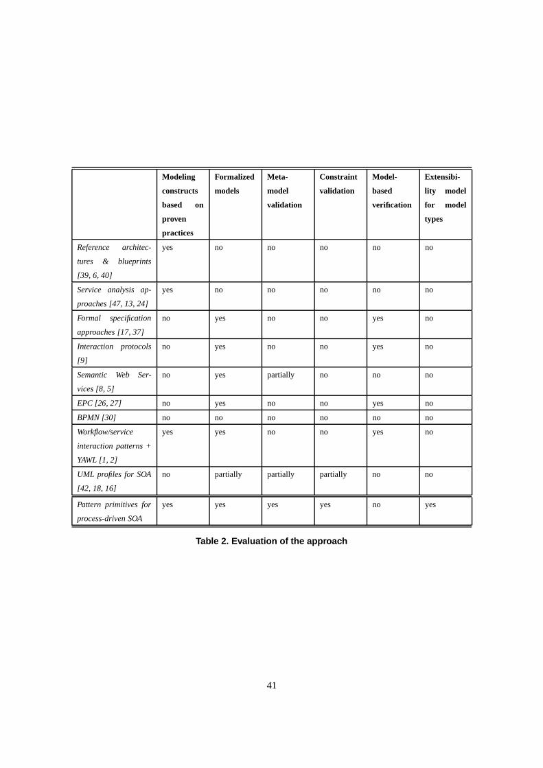
Modeling
constructs
based on
proven
practices
Formalized
models
Meta-
model
validation
Constraint
validation
Model-
based
verification
Extensibi-
lity model
for model
types
Reference architec-
tures & blueprints
[39, 6, 40]
yes no no no no no
Service analysis ap-
proaches [47, 13, 24]
yes no no no no no
Formal specification
approaches [17, 37]
no yes no no yes no
Interaction protocols
[9]
no yes no no yes no
Semantic Web Ser-
vices [8, 5]
no yes partially no no no
EPC [26, 27] no yes no no yes no
BPMN [30] no no no no no no
Workflow/service
interaction patterns +
YAWL [1, 2]
yes yes no no yes no
UML profiles for SOA
[42, 18, 16]
no partially partially partially no no
Pattern primitives for
process-driven SOA
yes yes yes yes no yes
Table 2. Evaluation of the approach
41

References
[1] W. Aalst, A. Hofstede, B. Kiepuszewski, and A. Barros. Workflow patterns. Distributed and Parallel Databases,
14:5–51, 2003.
[2] A. Barros, M. Dumas, and A. ter Hofstede. Service interaction patterns. In Proceedings of the 3rd Interna-
tional Conference on Business Process Management, pages 302–318, Nancy, France, September 2005. Springer
Verlag.
[3] D. K. Barry. Web Services and Service-oriented Architectures. Morgan Kaufmann Publishers, San Francisco,
CA, 2003.
[4] F. Buschmann, R. Meunier, H. Rohnert, P. Sommerlad, and M. Stal. Pattern-oriented Software Architecture - A
System of Patterns. J. Wiley and Sons Ltd., 1996.
[5] J. Cardoso and A. Sheth. Semantic e-workflow composition. J. Intell. Inf. Syst., 21(3):191–225, 2003.
[6] M. Champion. Towards a reference architecture for Web services. http://www.idealliance.org/papers/dx xml03/
papers/04-01-01/04-01-01.pdf, 2004.
[7] K. Channabasavaiah, K. Holley, and E. Tuggle. Migrating to service-oriented architecture – part 1. http://
www-106.ibm.com/developerworks/webservices/, 2003.
[8] DAML Services. OWL-S 1.1 Release. http://www.daml.org/services/owl-s/1.1/, 2004.
[9] N. Desai, A. U. Mallya, A. K. Chopra, and M. P. Singh. Interaction protocols as design abstractions for business
processes. IEEE Transactions on Software Engineering, 31(12):1015–1027, 2005.
[10] M. Dodani. Where’s the SOA Beef? Journal of Object Technology, 3(10):41–46, 2004.
[11] S. Dustdar and W. Schreiner. A survey on Web services composition. International Journal of Web and Grid
Services, 1(1):1–30, 2005.
[12] A. H. Eden and Y. Hirshfeld. LePUS – symbolic logic modeling of object oriented architectures: A case study.
In Second Nordic Workshop on Software Architecture - NOSA’99, Ronneby, Sweden, April 1999.
[13] T. Erl. Service-Oriented Architecture (SOA): Concepts, Technology, and Design. Prentice Hall PTR, 2005.
[14] E. Evans. Domain-Driven Design – Tackling Complexity in the Heart of Software. Addison-Wesley, 2004.
[15] E. Gamma, R. Helm, R. Johnson, and J. Vlissides. Design Patterns: Elements of Reusable Object-Oriented
Software. Addison-Wesley, 1994.
42
[16] T. Gardner. UML modeling of automated business processes with a mapping to BPEL4WS. In ECOOP
Workshop on Object Orientation and Web Services, Darmstadt, Germany, July 2003.
[17] C. E. Gerede, R. Hull, O. Ibarra, and J. Su. Automated composition of e-services: Lookaheads. In Proceedings
of the International Conference on Service Oriented Computing (ICSOC 2004), pages 252–262, New York, NY,
US, June 2004.
[18] R. Heckel, M. Lohmann, and S. Thoene. Towards a UML profile for service-oriented architectures. In Workshop
on Model Driven Architecture: Foundations and Applications (MDAFA) 2003, CTIT Technical Report TR-CTIT-
03-27, University of Twente, Enschede, The Netherlands, June 2003.
[19] C. Hentrich and U. Zdun. Patterns for process-oriented integration in service-oriented architectures. In Pro-
ceedings of 11th European Conference on Pattern Languages of Programs (EuroPlop 2006), pages 141–189,
Irsee, Germany, July 2006.
[20] G. Hohpe and B. Woolf. Enterprise Integration Patterns. Addison-Wesley, 2003.
[21] IBM. WebSphere Message Broker. http://www-306.ibm.com/software/integration/wbimessagebroker/, 2007.
[22] IBM. WebSphere MQ. http://www-306.ibm.com/software/integration/wmq/, 2007.
[23] IBM. WebSphere MQ Workflow. http://www-306.ibm.com/software/integration/wmqwf/, 2007.
[24] S. Jones. Enterprise SOA Adoption Strategies. InfoQ Mini-Book Series, http://www.infoq.com/minibooks/
enterprise-soa, 2006.
[25] M. Keen. Patterns: Implementing an SOA using an Enterprise Service Bus. IBM Redbooks, 2004.
[26] G. Keller, M. Nuettgens, and A.-W. Scheer. Prozessmodellierung auf der Grundlage Ereignisgesteuerter
Prozessketten (EPK). Technical Report Veroeffentlichungen des Instituts fr Wirtschaftsinformatik (IWi), Heft
89, Universitaet des Saarlandes, 1992.
[27] E. Kindler. On the semantics of EPCs: Resolving the vicious circle. Data & Knowledge Engineering, 56(1):23–
40, 2006. Elsevier.
[28] J. Mak, C. Choy, and D. Lun. Precise modeling of design patterns in UML. In Proceedings of the 26th
International Conference on Software Engineering (ICSE’04), pages 252–261, Edinburgh, Scotland, United
Kingdom, 2004. IEEE Computer Society.
[29] T. Mikkonen. Formalizing design patterns. In Proceedings of the 20th International Conference on Software
Engineering, pages 115–124, Kyoto, Japan, 1998. IEEE Computer Society.
[30] Object Management Group. Business Process Modeling Notation (BPMN). http://www.bpmn.org/, 2006.
43
[31] OMG. UML 2.0 OCL final adopted specification. Technical Report ptc/03-10-14, Object Management Group,
October 2003.
[32] OMG. UML 2.0 superstructure final adopted specification. Technical Report ptc/04-10-02, Object Management
Group, October 2004.
[33] Oracle. Metasolv. http://www.metasolv.com/MSLV/CDA/General/ProdSrvs Home.aspx?id=1, 2007.
[34] J. Rao and X. Su. A survey of automated Web service composition methods. In Proceedings of the First
International Workshop on Semantic Web Services and Web Process Composition, SWSWPC 2004, pages 43–
54, San Diego, California, USA, 2004. Springer-Verlag.
[35] D. Schmidt and F. Buschmann. Patterns, frameworks, and middleware: Their synergistic relationships. In 25th
International Conference on Software Engineering, pages 694–704, May 2003.
[36] Selectica. Automated Configuration Solutions. http://www.selectica.com/configure/enterprise configuration/
index.html, 2007.
[37] M. Solanki, A. Cau, and H. Zedan. Augmenting semantic web service descriptions with compositional speci-
fication. In WWW ’04: Proceedings of the 13th international conference on World Wide Web, pages 544–552,
2004.
[38] N. Soundarajan and J. O. Hallstrom. Responsibilities and rewards: Specifying design patterns. In Proceedings
of the 26th International Conference on Software Engineering, pages 666–675. IEEE Computer Society, 2004.
[39] Sun. Sun reference architectures. http://www.sun.com/service/refarch/, 2004.
[40] The Middleware Company. SOA blueprints. http://www.middlewareresearch.com/soa-blueprints/, 2004.
[41] S. Vinoski. Integration with Web services. IEEE Internet Computing, pages 75–77, November/December 2003.
[42] H. Wada, J. Suzuki, and K. Oba. Modeling non-functional aspects in service oriented architecture. In Proc.
of the 2006 IEEE International Conference on Service Computing, pages 222 – 229, Chicago, IL, September
2006.
[43] U. Zdun. Frag. http://frag.sourceforge.net/, 2005.
[44] U. Zdun. Tailorable language for behavioral composition and configuration of software components. Computer
Languages, Systems and Structures: An International Journal, 32(1):56–82, 2006.
[45] U. Zdun and P. Avgeriou. Modeling architectural patterns using architectural primitives. In Proceedings of
the 20th ACM Conference on Object-Oriented Programming, Systems, Languages & Applications (OOPSLA
2005), pages 133–146, San Diego, CA, USA, October 2005. ACM Press.
44

[46] U. Zdun, C. Hentrich, and W. van der Aalst. A survey of patterns for service-oriented architectures. Interna-
tional Journal of Internet Protocol Technology, 1(3):132–143, 2006.
[47] O. Zimmermann, P. Krogdahl, and C. Gee. Elements of Service-Oriented Analysis and Design: An interdis-
ciplinary modeling approach for SOA projects. http://www-128.ibm.com/developerworks/webservices/library/
ws-soad1/, Jun 2004.
45