Embed Size (px)
Citation preview

MODELING PROTOCOLSUPPLEMENT FOR THE HYDROGENENERGY CALIFORNIA (HECA)PROJECT
Prepared for:
U.S. Environmental Protection AgencyRegion IXCalifornia Energy CommissionSan Joaquin Valley Air Pollution ControlDistrict
Prepared on behalf of:
Hydrogen Energy California LLC
February 21, 2012
DATE RECD.
DOCKET08-AFC-8A
FEB 21 2012
FEB 21 2012


Hydrogen Energy California (HECA) Modeling Protocol Supplement
i
Table of Contents
1. INTRODUCTION .............................................................................................. 1
2. PROJECT DESCRIPTION ............................................................................... 12.1 Fertilizer Plant .......................................................................................... 3
3. CAAQS AND NAAQS MODELING FOR U.S. EPA AND SJVAPCDPERMITS ........................................................................................................... 53.1 AQRV AND CLASS I AREA ANALYSES ............................................. 73.2 CLASS II AREA VISIBILITY ANALYSIS ............................................. 8
4. CEQA/NEPA MODELING APPROACH FOR CEC ...................................... 8
5. METEOROLOGICAL AND BACKGROUND DATA .................................... 9
6. NO2 1-HOUR NAAQS MODELING APPROACH .......................................... 9
7. REFERENCES................................................................................................. 11
Tables
Table 1 Attainment Status for Kern County with Respect toFederal and California Ambient Air Quality Standards
Table 2 PSD Emission Threshold Triggers for New Stationary Sources
Figures
Figure 1 Preliminary Emissions Sources Plot Plan

Hydrogen Energy California (HECA) Modeling Protocol Supplement
ii
Acronyms and Abbreviations
AERMOD American Meteorological Society/Environmental Protection AgencyRegulatory Model
AFC Revised Application for CertificationAGR acid gas removalAOI area of impactASU Ammonia Synthesis UnitATC Application to ConstructBACT Best Available Control TechnologyCAAQS California Ambient Air Quality StandardCEC California Energy CommissionCEQA California Environmental Quality ActCO carbon monoxideCO2 carbon dioxideCT combustion turbineCTG/HRSG combustion turbine generator and heat recovery steam generatorDPM diesel particulate matterEOR enhanced oil recoveryFLAG Federal Land Managers’ Air Quality Related Values Work GroupHECA Hydrogen Energy CaliforniaHNO3 nitric acidHRA Health Risk AssessmentHRSG heat-recovery steam generatorIGCC integrated gasification combined-cycleMHI Mitsubishi Heavy IndustriesMMBtu/hr Million British thermal units per hourN2O nitrous oxideNAAQS National Ambient Air Quality StandardNH2-CO-NH2 ureaNH3 ammoniaNH4 ammonium nitrateNO nitric oxideNO2 nitrogen dioxideNOX nitrogen oxidesNPS National Park ServiceOLM ozone-limiting methodpetcoke petroleum cokePM10 particulate matter with aerodynamic diameter less than 10 micronsPM2.5 particulate matter with aerodynamic diameter less than 2.5 micronsppm parts per millionPSA Pressure Swing AdsorptionPSD Prevention of Significant DeteriorationSCR selective catalytic reductionSCS SCS Energy California LLCSIL Significant Impact Level

Hydrogen Energy California (HECA) Modeling Protocol Supplement
iii
SJVAPCD San Joaquin Valley Air Pollution Control DistrictSO2 sulfur dioxideTAC toxic air contaminantU.S. EPA United States Environmental Protection AgencyUAN urea ammonia nitrate


Hydrogen Energy California (HECA) Modeling Protocol Supplement
1
1. INTRODUCTION
Following acquisition of the Hydrogen Energy California (HECA) Project in September, 2011,SCS Energy California LLC (SCS) proposed modifications to the previous design, including theaddition of an integrated Fertilizer Complex. Due to the change in ownership and plantmodifications, San Joaquin Valley Air Pollution Control District (SJVAPCD) requires a newapplication to construct (ATC). The California Energy Commission (CEC) and the United StatesEnvironmental Protection Agency (U.S. EPA) also require revised air quality modeling analysesthat incorporate the modified facility sources.
This document supplements the two previous modeling protocols submitted to SJVAPCD, CEC,and U.S. EPA. On April 22, 2008, URS submitted the “Air Quality Modeling Protocol for theHydrogen Energy California (HECA) Project.” U.S. EPA, CEC, National Park Service (NPS),and U.S. Forest Service provided minor comments on the 2008 protocol, which were addressedin the previous analyses and have been incorporated into this supplement.
On January 20, 2011, URS submitted to SJVAPCD, CEC, and U.S. EPA the “Modeling Protocolfor Parameter Selection Specific to the 1-Hour NO2 NAAQS Regional Modeling for theHydrogen Energy California (HECA) Project.” On March 11, 2011, U.S. EPA approved theJanuary 2011 modeling protocol, with the caveat that the new March 1, 2011 U.S. EPA guidancedocument may afford additional flexibility on some parameters; thus, a modification of theprotocol in some respects may be possible in the near future.
Due to recent changes in some national ambient air quality standards (NAAQS) and associatedmodeling guidance, some analyses may be conducted differently than described in the previousmodeling protocols. This supplement outlines only the differences in the techniques that will beused to conduct the modeling of the revised facility for both the NAAQS and California ambientair quality standards (CAAQS). Techniques described and approved in the previous protocolsthat will not change are not described here. A brief discussion of previous techniques is includedonly where clarification is needed.
2. PROJECT DESCRIPTION
Many Project components remain unchanged from previous application submittals. As before,the HECA Project will consist of an Integrated Gasification Combined Cycle (IGCC) facility toproduce low-carbon baseload electricity by capturing carbon dioxide (CO2) and transporting itfor Enhanced Oil Recovery (EOR) and sequestration. The HECA Project location has remainedunchanged, and is located approximately 7 miles west of the outermost edge of the City ofBakersfield, and 1.5 miles northwest of the unincorporated community of Tupman in westernKern County, California, in the San Joaquin Valley Air Basin. Key environmental controls alsoremain incorporated into the design such as the use of state-of-the-art emission controltechnologies, brackish water supply for process water needs and Zero Liquid Dischargetechnology.
.
Hydrogen Energy California (HECA) Modeling Protocol Supplement
2
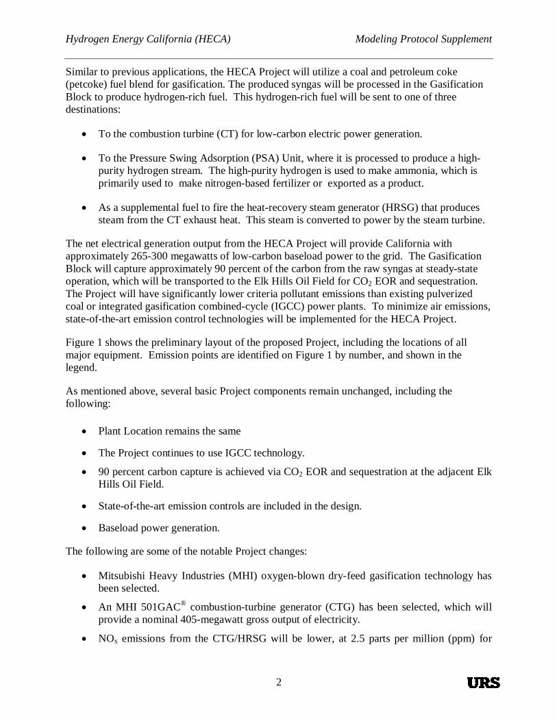
Similar to previous applications, the HECA Project will utilize a coal and petroleum coke(petcoke) fuel blend for gasification. The produced syngas will be processed in the GasificationBlock to produce hydrogen-rich fuel. This hydrogen-rich fuel will be sent to one of threedestinations:
To the combustion turbine (CT) for low-carbon electric power generation.
To the Pressure Swing Adsorption (PSA) Unit, where it is processed to produce a high-purity hydrogen stream. The high-purity hydrogen is used to make ammonia, which isprimarily used to make nitrogen-based fertilizer or exported as a product.
As a supplemental fuel to fire the heat-recovery steam generator (HRSG) that producessteam from the CT exhaust heat. This steam is converted to power by the steam turbine.
The net electrical generation output from the HECA Project will provide California withapproximately 265-300 megawatts of low-carbon baseload power to the grid. The GasificationBlock will capture approximately 90 percent of the carbon from the raw syngas at steady-stateoperation, which will be transported to the Elk Hills Oil Field for CO2 EOR and sequestration.The Project will have significantly lower criteria pollutant emissions than existing pulverizedcoal or integrated gasification combined-cycle (IGCC) power plants. To minimize air emissions,state-of-the-art emission control technologies will be implemented for the HECA Project.
Figure 1 shows the preliminary layout of the proposed Project, including the locations of allmajor equipment. Emission points are identified on Figure 1 by number, and shown in thelegend.
As mentioned above, several basic Project components remain unchanged, including thefollowing:
Plant Location remains the same
The Project continues to use IGCC technology.
90 percent carbon capture is achieved via CO2 EOR and sequestration at the adjacent ElkHills Oil Field.
State-of-the-art emission controls are included in the design.
Baseload power generation.
The following are some of the notable Project changes:
Mitsubishi Heavy Industries (MHI) oxygen-blown dry-feed gasification technology hasbeen selected.
An MHI 501GAC® combustion-turbine generator (CTG) has been selected, which willprovide a nominal 405-megawatt gross output of electricity.
NOx emissions from the CTG/HRSG will be lower, at 2.5 parts per million (ppm) for

Hydrogen Energy California (HECA) Modeling Protocol Supplement
3
hydrogen-rich fuel.
Anhydrous ammonia (produced onsite) will be used with the selective catalytic reduction(SCR).
The three 18-million British thermal units per hour (MMBtu/hr) gasifier preheaters andthe methanol startup system are not needed with the MHI gasifier. The gasifier willinstead be pre-heated and started using a natural feed burner/nozzle under a much shortertime duration.
A new rail spur will be constructed to the Project Site in order to facilitate feedstock andequipment delivery, as well as fertilizer and product off-take.
A new, integrated fertilizer complex will produce approximately 1 million tons per yearof nitrogen-based fertilizer.
A 75 percent coal and 25 percent petcoke fuel blend will be used for the life of thefacility.
Additional baghouses to control fugitive dust associated with feedstock and productmaterial handling.
Some modification to the routes of the natural gas pipeline, potable water pipeline, andelectrical transmission lines.
2.1 FERTILIZER PLANT
A brief description of the fertilizer plant and its components and emission sources is presentedbelow.
Two Pressure Swing Adsorption Units
The PSA units will take a portion of clean syngas from the Acid Gas Removal (AGR) Unit togenerate a high-purity hydrogen gas stream for use as a feedstock to the Ammonia SynthesisUnit (ASU). The off-gas from the PSA unit is compressed and sent to the HRSG for use as duct-burner fuel.
Ammonia Synthesis Unit
The high-purity hydrogen stream, from the PSA Unit, and nitrogen, from the ASU, are combinedin an exothermic ammonia synthesis reaction that takes place at high temperature and highpressure across an iron-based catalyst. There is a large degree of heat integration within theAmmonia Synthesis Unit, and the substantial heat of reaction is recovered and used to generatesteam. Cold liquid ammonia is stored in a tank at atmospheric pressure. A 55-MMBtu/hrnatural-gas–fired startup heater is provided in the Ammonia Synthesis Unit to raise the catalyst-bed temperatures during initial plant commissioning or during startup after a long period of plantshutdown. The heater will use a low-NOx burner to control emissions to 9 ppm.
Urea Unit

Hydrogen Energy California (HECA) Modeling Protocol Supplement
4
The purified and compressed carbon dioxide and the liquid ammonia are reacted in the Urea Unitto create a concentrated urea solution, which is pumped to the Urea Pastillation Unit. Lower-concentration urea solution is produced as a feedstock to the urea ammonia nitrate (UAN)Solution Plant. Vacuum evaporator/separator systems are used to produce the required ureasolutions. Vapors from the vacuum system are scrubbed in an absorber using processcondensates. The treated vapors, essentially inerts, and some ammonia, are released to theatmosphere from the medium-pressure and low-pressure absorber stacks.

Hydrogen Energy California (HECA) Modeling Protocol Supplement
5
Urea Pastillation Unit
The pastillation process is used to convert the urea melt into high-quality pastilles. This processis enclosed with a hood, passed through a wet scrubber, then vented to the atmosphere. Limitedammonia and urea dust are emitted from this source. The urea pastille is transferred via enclosedconveyors to an enclosed storage structure equipped with a baghouse to control fugitive dust.
Nitric Acid Unit
Nitric acid production is a three-step process consisting of ammonia oxidation, nitric oxide (NO)oxidation, and absorption. Tail gas from the absorber column will be cleaned before beingdischarged to the atmosphere by catalytic decomposition and reduction of both nitrous oxide(N2O) and NOx. The tail-gas-abatement unit complies with the application of Best AvailableControl Technology (BACT).
Ammonium Nitrate Unit
The ammonia and nitric acid are the feedstocks to the Ammonium Nitrate Unit, which makes theammonium nitrate solution. Particulate matter is emitted from the Ammonium Nitrate Unit, andwill be minimized with a wet scrubber.
UAN Solution Unit
In order to produce UAN solution, it is necessary to combine nitric acid (HNO3), ammoniumnitrate (NH4NO3), and urea (NH2-CO-NH2), produced in previous processes.
3. CAAQS AND NAAQS MODELING FOR U.S. EPA AND SJVAPCD PERMITS
To determine the analyses required, the attainment status of the Project region is needed, alongwith the expected annual emissions from the Project. Table 1 describes the attainment status ofKern County. Table 2 presents the estimated annual Project emissions and the pollutants forwhich Prevention of Significant Deterioration (PSD) is applicable. Emissions of the newlyrevised HECA Project have decreased for nitrogen dioxide (NO2) and CO, and remained similarfor the other pollutants.

Hydrogen Energy California (HECA) Modeling Protocol Supplement
6
Table 1Attainment Status for Kern County with Respect to
Federal and California Ambient Air Quality Standards
Pollutant Federal Attainment Status State Attainment Status
Ozone Extreme Non-attainment Non-attainment
CO Attainment Attainment
NO2 Attainment Attainment
SO2 Attainment Attainment
PM10 Attainment Non-attainment
PM2.5 Non-attainment Non-attainment
Lead Unclassified AttainmentSource: CARB 2012Notes:CO = carbon monoxideNO2 = nitrogen dioxidePM10 = particulate matter less than 10 microns in diameterPM2.5 = particulate matter less than 2.5 microns in diameterSO2 = sulfur dioxide
Table 2PSD Emission Threshold Triggers for New Stationary Sources
PollutantPSD ApplicabilityThresholds (tpy)
SignificantEmission Rate
(tpy)
PreliminaryEstimated Project
Emissions (tpy)PSD Triggered by
Project?CO 100 100 288 YesSO2 100 40 37 NoNOX 100 40 152 YesPM10 100 15 95 YesPM2.5 100 10 84 No Non-attainmentVOCs 100 40 40 YesCO2 100,000 NA >100,000 YesLead (Pb) NA 0.6 <0.6 NoMercury (Hg) NA 0.1 0.01 NoSulfuric acid mist (H2SO4) NA 7 ~6 NoHydrogen sulfide (H2S) NA 10 ~4 NoTotal reduced sulfur (TRS) NA 10 ~6 NoSource: 40 CFR § 52.21 and HECA Project.Notes:CO = carbon monoxideCO2 = carbon dioxideNOx = nitrogen dioxidePM2.5 = particulate matter less than 2.5 microns in diameterPM10 = particulate matter less than 10 microns in diameterPSD = Prevention of Significant DeteriorationSO2 = sulfur dioxideVOC = volatile organic compound

Hydrogen Energy California (HECA) Modeling Protocol Supplement
7
Modeling for compliance with all CAAQS and NAAQS will be conducted, with the exceptionthat no modeling will be conducted for ozone or the revoked SO2 annual and 24-hour NAAQS.The most recent version of American Meteorological Society/U.S. EPA Regulatory Model(AERMOD) will be used, which is currently version 11353.
PSD modeling will be conducted to determine if impacts are less than the Significant ImpactLevel (SIL) for NO2 1-hour and annual, and PM10 24-hour and annual. It is expected that themodeling for NO2 1-hour impacts will be greater than the SIL, while impacts for the otherpollutants and averaging times are expected to be less than the applicable SIL. Therefore, theonly refined cumulative analysis expected to be conducted would be for the NO2 1-hour NAAQS(described later).
Because the Project is located in a federal non-attainment area for PM2.5, PSD modeling will notbe needed for PM2.5 impacts, although SJVAPCD has “Procedures for Modeling PM2.5,” andmodeling will be conducted following this guidance. Because HECA is expected to be a minorsource of PM2.5 emissions, this modeling will examine the impacts from directly emitted PM2.5,and no secondarily formed PM2.5 will be included in the analysis. Both the filterable andcondensable portions of the PM2.5 will be included in the emissions and impact modeling.Per U.S. EPA and SJVAPCD guidance, all modeling conducted for PSD and NAAQScompliance will include permitted source emissions, but no mobile-related emissions will beincluded. For California Environmental Quality Act (CEQA) compliance, all modeling for theCAAQSs will include both permitted source emissions and mobile source emissions. Allpermitted sources will be modeled using their maximum potential emission rate from eithernormal or startup/shutdown operations for all CAAQS and NAAQS, with the exception of theNO2 and SO2 1-hour NAAQS modeling analyses (described later).
3.1 AQRV AND CLASS I AREA ANALYSES
The nearest Class I Area to the HECA Project is Domelands Wilderness Area, approximately60 kilometers away. The updated FLAG guidance, “Federal Land Managers’ Air QualityRelated Values Work Group (FLAG),” provides a method to determine if projects greater than50 kilometers from a Class I Area need to conduct analyses in the Class I Area. This screeningmethod is based on the sum of the annualized daily emissions of PM10, NO2, SO2, and H2SO4emissions divided by the distance to the nearest Class I Area (Q/d). The Q/d value for the HECAProject to Domelands is approximately 5, which is less than the screening threshold of 10;therefore HECA will not prepare Class I Area analyses.
It should be noted that in the previous PSD application, HECA prepared Class I Area analyses,all of which showed less-than-significant impacts. The emissions of the newly revised HECAProject have decreased or stayed similar; thus, impacts should decrease or remain similar, andimpacts from the HECA Project in Class I Areas would remain less than significant.

Hydrogen Energy California (HECA) Modeling Protocol Supplement
8
3.2 CLASS II AREA VISIBILITY ANALYSIS
NPS PSD guidance states that projects should not degrade air quality and/or visibility in Class IIareas. Class II areas are defined as the following areas when greater than 10,000 acres, and inexistence since 1977:
National monuments;
National primitive areas;
National preserves;
National recreation areas;
National wild and scenic rivers;
National wildlife refuges;
National lakeshores and seashores; and
National parks and wilderness areas.
The nearest parks that fit the Class II area definition are Sequoia National Forest, approximately55 kilometers away; and Los Padres National Forest, approximately 50 kilometers away fromHECA. Since both of these parks are 50 kilometers or greater from HECA, and the Q/d isapproximately 6 (when d=50 kilometers), per the FLAG guidance screening technique, impactswould be less than significant. Therefore, no Class II Area visibility analysis will be conducted.
4. CEQA/NEPA MODELING APPROACH FOR CEC
In addition to the analyses required for U.S. EPA and SJVAPCD permitting, CEC requiresanalyses for compliance with CEQA.
To analyze the impacts from all emissions associated with the Project for CEQA, modeling willbe conducted for both the construction and operational phases of the Project. The operational-phase modeling will include emissions from the permitted stationary sources, and from theexhaust and fugitive dust from the mobile sources (trucks and train) associated with the deliveryand off-take of feedstock and products, and operations and maintenance. Emissions from on-road vehicles will be estimated using EMFAC2007, because this is the version of the model thatis approved for federal projects. Modeling results plus a representative background will becompared to the CAAQS.
Due to the short duration of construction activities, the variability of equipment usage, and thestatistical nature of the NO2 and SO2 1-hour NAAQS, construction impacts will not be comparedto these standards. Construction impacts will be compared to the NO2 and SO2 1-hour CAAQS.Similarly, impacts from commissioning activities will not be compared to the NO2 and SO2 1-hour NAAQS, although they will be compared to the NO2 and SO2 1-hour CAAQS.

Hydrogen Energy California (HECA) Modeling Protocol Supplement
9
The operational-phase analysis for the NO2 and SO2 1-hour CAAQS will include maximumhourly emissions from sources with intermittent operations. AERMOD will be run separately foreach year of meteorological data to obtain the peak hourly impact from the 5 years.
As identified in the response to CEC Data Request 32, there are no sources within 6 miles ofHECA that emit more than 5 tons per year of any criteria pollutant that have been recentlypermitted or are in the process of being permitted. SJVAPCD was contacted and will identify ifany sources have recently been permitted or are in the process of being permitted for 2010 and2011. It is expected that there are no new sources that meet the 5 ton per year criteria; therefore,cumulative modeling for CEQA will not be conducted. If any sources are identified, URS willcontact CEC to determine the appropriate analysis.
To evaluate potential health effects of toxic air contaminant (TAC) emissions from the operationof the Project, a health risk assessment (HRA) will be conducted. During construction, the mainTAC of concern is diesel particulate matter (DPM). An HRA will be conducted to assess theDPM from the construction equipment and delivery vehicle exhaust on the Project site. ThisHRA will assess the risk from the approximate 3-year construction period exposure, not a 70-year exposure.
5. METEOROLOGICAL AND BACKGROUND DATA
HECA will use the most recent 5-year meteorological, ozone, and NO2 data set processed bySJVAPCD in all the modeling analyses. The meteorological data are from the same station usedin the previous analyses: Bakersfield Meadows Field Airport for years 2007-2011. SJVAPCDhas also prepared hourly ozone and NO2 data sets for the same period from the Shafter, WalkerStreet station.
6. NO2 1-HOUR NAAQS MODELING APPROACH
In addition to techniques described in the January 20, 2011 “Modeling Protocol for ParameterSelection Specific to the 1-Hour NO2 NAAQS Regional Modeling for the Hydrogen EnergyCalifornia (HECA) Project,” HECA will conduct the NO2 1-hour NAAQS analysis incorporatingguidance from three documents, the U.S. EPA “Additional Clarification Regarding Applicationof Appendix W Modeling Guidance for the 1-hour NO2 National Ambient Air QualityStandard,” March 2011; CAPCOA “Modeling Compliance of The Federal 1-Hour NO2NAAQS,” October 2011; and SJVAPCD “Assessment of Non-Regulatory Option in AERMODSpecifically OLM and PVMRM,” September 2010.
The changes to the modeling techniques for the 1-hour NO2 analysis described below areprimarily a result of the March 1, 2011, U.S. EPA–published guidance document for conducting1-hour NO2 and SO2 NAAQS analyses called “Additional Clarification Regarding Application ofAppendix W Modeling Guidance for the 1-hour NO2 National Ambient Air Quality Standard.”
Nearby sources with intermittent emissions will not be included in the cumulative 1-hour NO2NAAQS analysis. No additional nearby sources will be included in the analysis beyond thoseidentified in the January 2011 NO2 1-hour modeling protocol, because it anticipated that there

Hydrogen Energy California (HECA) Modeling Protocol Supplement
10
are no new significant sources near HECA. If new sources are identified that meet the criteriaoutlined in the January 2011 modeling protocol, they will be included in the analysis.
Intermittent sources associated with the HECA Project will be included in the NO2 1-hour (andSO2 1-hour) NAAQS modeling analysis using the higher of either their normal operationalemission rates, or their annualized intermittent emission rates. These sources include the testingof the emergency generators and fire-water pump, along with each emission source in startupmode. It is expected that HECA will have two planned facility startups and shutdowns per year,in which each affected emission source will be in startup/shutdown mode for between 30 minutesto 52 hours. Only the flares, CTG/HRSG, coal dryer, and thermal oxidizer emissions vary instartup mode from their normal operational emissions.
The area of impact (AOI) will be determined from the SIL analysis, and will be limited to50 kilometers. The AOI is the area where the Project impacts are greater than or equal to theSIL. Only receptors that are shown to have Project impacts greater than or equal to the SIL willbe included in the cumulative modeling.
All other aspects for the NO2 analysis will be performed as described in the January 20, 2011“Modeling Protocol for Parameter Selection Specific to the 1-Hour NO2 NAAQS RegionalModeling for the Hydrogen Energy California (HECA) Project.”

Hydrogen Energy California (HECA) Modeling Protocol Supplement
11
7. REFERENCES
California Air Resources Board (CARB), 2012. Standards and Area Designations,http://www.arb.ca.gov/desig/desig.htm, February 6, 2012.
California Air Pollution Control Officers Association (CAPCOA), 2011. Modeling Complianceof the Federal 1-Hour NO2 NAAQS, October 27.
National Park Service (NPS), 2006. PSD – Prevention of Significant Deterioration,http://www.nature.nps.gov/air/regs/psd.cfm, November 2.
National Park Service (NPS), 2010. Federal Land Managers’ Air Quality Related Values WorkGroup (FLAG), Phase I Report – Revised (2010), October.
SJVAPCD (San Joaquin Valley Air Pollution Control District), 2010. Procedures forDownloading and Processing NCDC Meteorological Data. Permit Services Department.Villalvazo, Leland and Ester Davila. May.
SJVAPCD, 2010. Assessment of Non-Regulatory Option in AERMOD Specifically OLM andPVMRM, September 16.
SJVAPCD (San Joaquin Valley Air Pollution Control District), 2011. Procedures for ModelingPM2.5. October 2011.
U.S. EPA (United States Environmental Protection Agency), 2005. Revision to the Guideline onAir Quality Models: Adoption of a Preferred General Purpose (Flat and ComplexTerrain) Dispersion Model and Other Revisions; Final Rule. 40 CFR Part 51.Appendix W, Guideline on Air Quality Models. November 9.
U.S. EPA (United States Environmental Protection Agency), 2010. Guidance Concerning theImplementation of the 1-hour NO2 NAAQS for the Prevention of Significant DeteriorationProgram. June 29.
U.S. EPA (United States Environmental Protection Agency), 2011. Additional ClarificationRegarding Application of Appendix W Modeling Guidance for the 1-hour NO2 NationalAmbient Air Quality Standard. March 1.
URS, 2008. Air Quality Modeling Protocol for the HECA Power Project, Kern County,California. April 22.
URS, 2011. Modeling Protocol for Parameter Selection Specific to the 1 Hour NO2 NAAQSRegional Modeling for the Hydrogen Energy California (HECA) Project. January 20.


FIGURES


FIGURE 1PRELIMINARY EMISSIONS SOURCES PLOT PLAN


PRELIMINARY

BEFORE THE ENERGY RESOURCES CONSERVATION AND DEVELOPMENT
COMMISSION OF THE STATE OF CALIFORNIA 1516 NINTH STREET, SACRAMENTO, CA 95814 1-800-822-6228 – WWW.ENERGY.CA.GOV
APPLICATION FOR CERTIFICATION Docket No. 08-AFC-8 FOR THE HYDROGEN ENERGY CALIFORNIA, LLC PROJECT
PROOF OF SERVICE (Revised 2/21/12)
APPLICANT SCS Energy LLC Marisa Mascaro 30 Monument Square, Suite 235 Concord, MA 01742 [email protected] APPLICANT’S CONSULTANT Dale Shileikis, Vice President Energy Services Manager Major Environmental Programs URS Corporation One Montgomery Street, Suite 900 San Francisco, CA 94104-4538 [email protected] COUNSEL FOR APPLICANT Michael J. Carroll Latham & Watkins, LLP 650 Town Center Drive, 20th Fl. Costa Mesa, CA 92626-1925 [email protected] INTERESTED AGENCIES California ISO [email protected] Marni Weber Department of Conservation, Office of Governmental and Environmental Relations (Department of Oil, Gas & Geothermal Resources) 801 K Street MS 2402 Sacramento, CA 95814-3530 [email protected]
INTERVENORS California Unions for Reliable Energy Thomas A. Enslow Marc D. Joseph Adams Broadwell Joseph & Cardozo 520 Capitol Mall, Suite 350 Sacramento, CA 95814 [email protected] Tom Frantz Association of Irritated Residents 30100 Orange Street Shafter, CA 93263 [email protected] Kern-Kaweah Chapter Of the Sierra Club Babak Naficy Law Offices of Babak Naficy 1504 Marsh Street San Luis Obispo, California 93401 [email protected] Environmental Defense Fund (EDF) Timothy O’Connor, Esq. 1107 Ninth St., Suite 540 Sacramento, CA 95814 [email protected] Natural Resources Defense Council George Peridas 111 Sutter Street, 20th Fl. San Francisco, CA 94104 [email protected]
ENERGY COMMISSION – DECISIONMAKERS Raoul Renaud Hearing Officer [email protected] ENERGY COMMISSION STAFF Alan Soloman Project Manager [email protected] Lisa De Carlo Staff Counsel [email protected] Eileen Allen Commissioners” Technical Advisor for Facility Siting e-mail service preferred [email protected] ENERGY COMMISSION – PUBLIC ADVISER Jennifer Jennings Public Adviser’s Office e-mail service preferred [email protected]

2
DECLARATION OF SERVICE
I, Dale Shileikis declare that on, February 21, 2012, I served and filed copies of the attached Modeling Protocol Supplement for the Hydrogen Energy California (HECA) Project . This document is accompanied by the most recent Proof of Service list, located on the web page for this project at: [www.energy.ca.gov/sitingcases/hydrogen_energy/ index.html]. The document has been sent to the other parties in this proceeding (as shown on the Proof of Service list) and to the Commission’s Docket Unit or Chief Counsel, as appropriate, in the following manner: (Check all that Apply)
FOR SERVICE TO ALL OTHER PARTIES:
Served electronically to all email addresses on the Proof of Service list; X Served by delivering on this date, either personally, for mailing with the U.S. Postal Service with
first-class postage thereon fully prepaid, to the name and address of the person served, for mailing that same day in the ordinary course of business; that the envelope was sealed and placed for collection and mailing on that date to those addresses NOT marked “email preferred.”
AND For filing with the Docket Unit at the Energy Commission: X by sending an original paper copy and one electronic copy, mailed with the U.S. Postal Service
with first class postage thereon fully prepaid and e-mailed respectively, to the address below (preferred method); OR
OR by depositing an original and 12 paper copies in the mail with the U.S. Postal Service with first
class postage thereon fully prepaid, as follows:
CALIFORNIA ENERGY COMMISSION – DOCKET UNIT Attn: Docket No. 08-AFC-8 1516 Ninth Street, MS-4 Sacramento, CA 95814-5512 [email protected]
OR, if filing a Petition for Reconsideration of Decision or Order pursuant to Title 20, § 1720: Served by delivering on this date one electronic copy by e-mail, and an original paper copy to the Chief Counsel at the following address, either personally, or for mailing with the U.S. Postal Service with first class postage thereon fully prepaid:
California Energy Commission Michael J. Levy, Chief Counsel 1516 Ninth Street MS-14 Sacramento, CA 95814 [email protected]
I declare under penalty of perjury under the laws of the State of California that the foregoing is true and correct, that I am employed in the county where this mailing occurred, and that I am over the age of 18 years and not a party to the proceeding.