Embed Size (px)
Citation preview
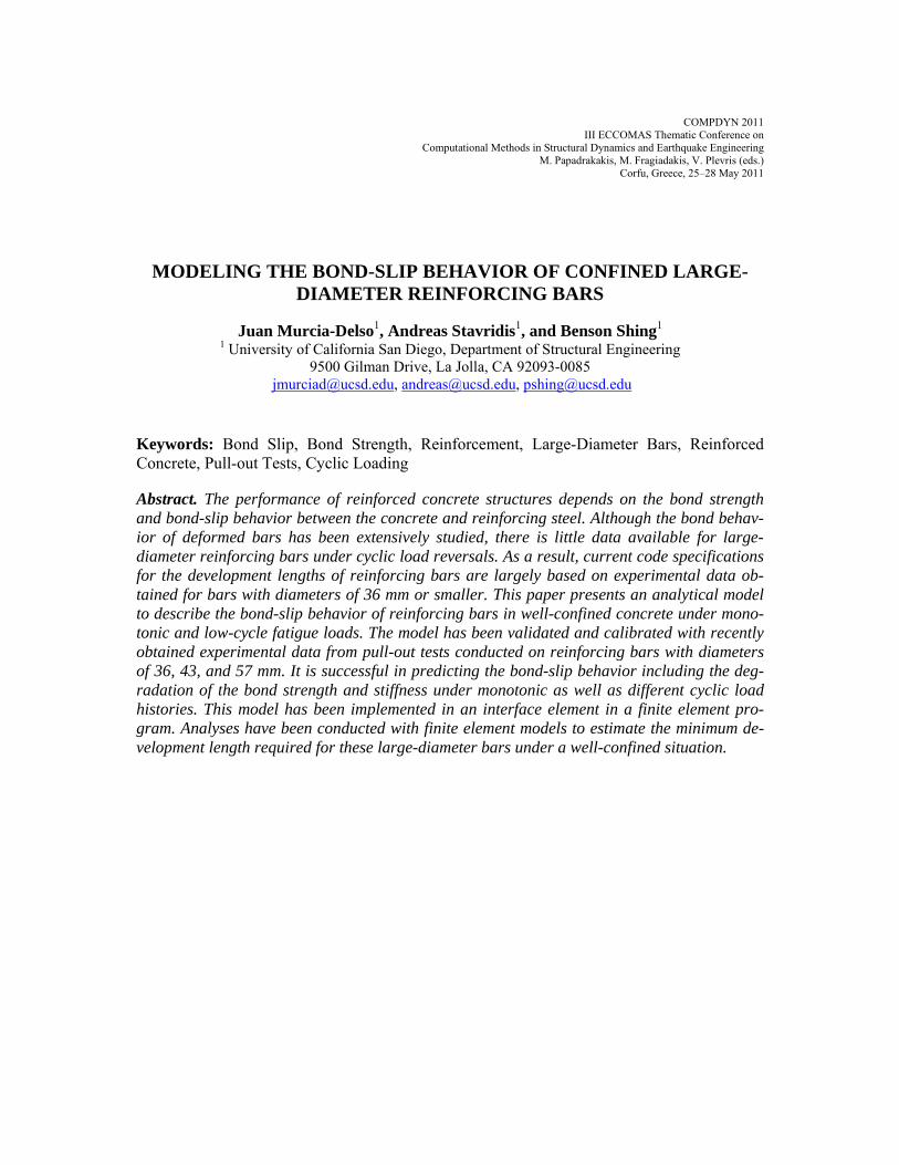
COMPDYN 2011 III ECCOMAS Thematic Conference on
Computational Methods in Structural Dynamics and Earthquake Engineering M. Papadrakakis, M. Fragiadakis, V. Plevris (eds.)
Corfu, Greece, 25–28 May 2011
MODELING THE BOND-SLIP BEHAVIOR OF CONFINED LARGE-DIAMETER REINFORCING BARS
Juan Murcia-Delso1, Andreas Stavridis1, and Benson Shing1 1 University of California San Diego, Department of Structural Engineering
9500 Gilman Drive, La Jolla, CA 92093-0085 [email protected], [email protected], [email protected]
Keywords: Bond Slip, Bond Strength, Reinforcement, Large-Diameter Bars, Reinforced Concrete, Pull-out Tests, Cyclic Loading
Abstract. The performance of reinforced concrete structures depends on the bond strength and bond-slip behavior between the concrete and reinforcing steel. Although the bond behav-ior of deformed bars has been extensively studied, there is little data available for large-diameter reinforcing bars under cyclic load reversals. As a result, current code specifications for the development lengths of reinforcing bars are largely based on experimental data ob-tained for bars with diameters of 36 mm or smaller. This paper presents an analytical model to describe the bond-slip behavior of reinforcing bars in well-confined concrete under mono-tonic and low-cycle fatigue loads. The model has been validated and calibrated with recently obtained experimental data from pull-out tests conducted on reinforcing bars with diameters of 36, 43, and 57 mm. It is successful in predicting the bond-slip behavior including the deg-radation of the bond strength and stiffness under monotonic as well as different cyclic load histories. This model has been implemented in an interface element in a finite element pro-gram. Analyses have been conducted with finite element models to estimate the minimum de-velopment length required for these large-diameter bars under a well-confined situation.
Juan Murcia-Delso, Andreas Stavridis and Benson Shing
2
1 INTRODUCTION
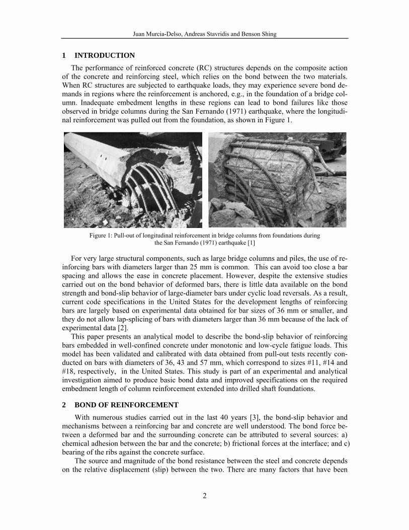
The performance of reinforced concrete (RC) structures depends on the composite action of the concrete and reinforcing steel, which relies on the bond between the two materials. When RC structures are subjected to earthquake loads, they may experience severe bond de-mands in regions where the reinforcement is anchored, e.g., in the foundation of a bridge col-umn. Inadequate embedment lengths in these regions can lead to bond failures like those observed in bridge columns during the San Fernando (1971) earthquake, where the longitudi-nal reinforcement was pulled out from the foundation, as shown in Figure 1.
Figure 1: Pull-out of longitudinal reinforcement in bridge columns from foundations during
the San Fernando (1971) earthquake [1]
For very large structural components, such as large bridge columns and piles, the use of re-inforcing bars with diameters larger than 25 mm is common. This can avoid too close a bar spacing and allows the ease in concrete placement. However, despite the extensive studies carried out on the bond behavior of deformed bars, there is little data available on the bond strength and bond-slip behavior of large-diameter bars under cyclic load reversals. As a result, current code specifications in the United States for the development lengths of reinforcing bars are largely based on experimental data obtained for bar sizes of 36 mm or smaller, and they do not allow lap-splicing of bars with diameters larger than 36 mm because of the lack of experimental data [2].
This paper presents an analytical model to describe the bond-slip behavior of reinforcing bars embedded in well-confined concrete under monotonic and low-cycle fatigue loads. This model has been validated and calibrated with data obtained from pull-out tests recently con-ducted on bars with diameters of 36, 43 and 57 mm, which correspond to sizes #11, #14 and #18, respectively, in the United States. This study is part of an experimental and analytical investigation aimed to produce basic bond data and improved specifications on the required embedment length of column reinforcement extended into drilled shaft foundations.
2 BOND OF REINFORCEMENT
With numerous studies carried out in the last 40 years [3], the bond-slip behavior and mechanisms between a reinforcing bar and concrete are well understood. The bond force be-tween a deformed bar and the surrounding concrete can be attributed to several sources: a) chemical adhesion between the bar and the concrete; b) frictional forces at the interface; and c) bearing of the ribs against the concrete surface.
The source and magnitude of the bond resistance between the steel and concrete depends on the relative displacement (slip) between the two. There are many factors that have been
Juan Murcia-Delso, Andreas Stavridis and Benson Shing
3
found to affect the bond strength: the bar size and deformation pattern, the compressive and tensile strengths of concrete, the aggregate size, the concrete cover, the transverse reinforce-ment, the casting position, the bar corrosion level, etc. [4]. A detailed explanation of bond-slip mechanisms can be found in [3] and [4]. They are briefly summarized below.
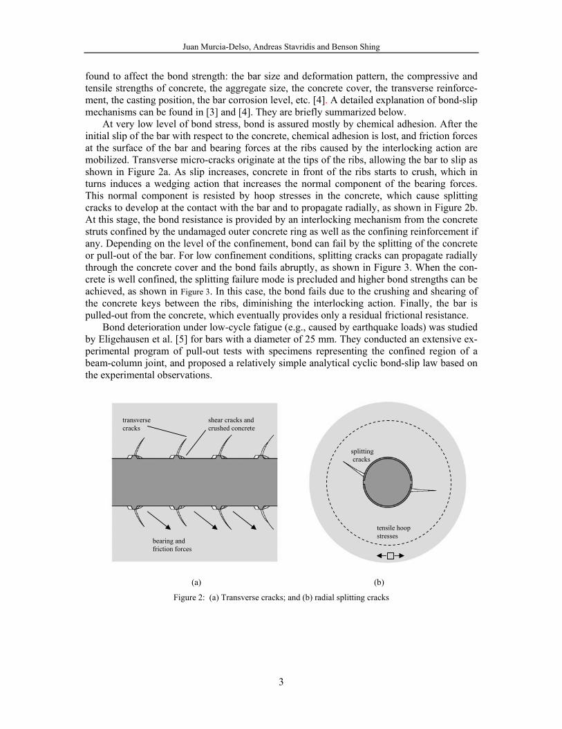
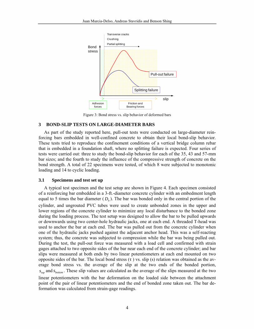
At very low level of bond stress, bond is assured mostly by chemical adhesion. After the initial slip of the bar with respect to the concrete, chemical adhesion is lost, and friction forces at the surface of the bar and bearing forces at the ribs caused by the interlocking action are mobilized. Transverse micro-cracks originate at the tips of the ribs, allowing the bar to slip as shown in Figure 2a. As slip increases, concrete in front of the ribs starts to crush, which in turns induces a wedging action that increases the normal component of the bearing forces. This normal component is resisted by hoop stresses in the concrete, which cause splitting cracks to develop at the contact with the bar and to propagate radially, as shown in Figure 2b. At this stage, the bond resistance is provided by an interlocking mechanism from the concrete struts confined by the undamaged outer concrete ring as well as the confining reinforcement if any. Depending on the level of the confinement, bond can fail by the splitting of the concrete or pull-out of the bar. For low confinement conditions, splitting cracks can propagate radially through the concrete cover and the bond fails abruptly, as shown in Figure 3. When the con-crete is well confined, the splitting failure mode is precluded and higher bond strengths can be achieved, as shown in Figure 3. In this case, the bond fails due to the crushing and shearing of the concrete keys between the ribs, diminishing the interlocking action. Finally, the bar is pulled-out from the concrete, which eventually provides only a residual frictional resistance.
Bond deterioration under low-cycle fatigue (e.g., caused by earthquake loads) was studied by Eligehausen et al. [5] for bars with a diameter of 25 mm. They conducted an extensive ex-perimental program of pull-out tests with specimens representing the confined region of a beam-column joint, and proposed a relatively simple analytical cyclic bond-slip law based on the experimental observations.
(a) (b)
Figure 2: (a) Transverse cracks; and (b) radial splitting cracks
splitting cracks
tensile hoop stresses
transverse cracks
shear cracks and crushed concrete
bearing and friction forces
Juan Murcia-Delso, Andreas Stavridis and Benson Shing
4
slipAdhesion
forces
Transverse cracks
Crushing
Partial splitting
Friction andBearing forces
Pull-out failure
Splitting failure
Bond stress
Figure 3: Bond stress vs. slip behavior of deformed bars
3 BOND-SLIP TESTS ON LARGE-DIAMETER BARS
As part of the study reported here, pull-out tests were conducted on large-diameter rein-forcing bars embedded in well-confined concrete to obtain their local bond-slip behavior. These tests tried to reproduce the confinement conditions of a vertical bridge column rebar that is embedded in a foundation shaft, where no splitting failure is expected. Four series of tests were carried out: three to study the bond-slip behavior for each of the 35, 43 and 57-mm bar sizes; and the fourth to study the influence of the compressive strength of concrete on the bond strength. A total of 22 specimens were tested, of which 8 were subjected to monotonic loading and 14 to cyclic loading.
3.1 Specimens and test set up
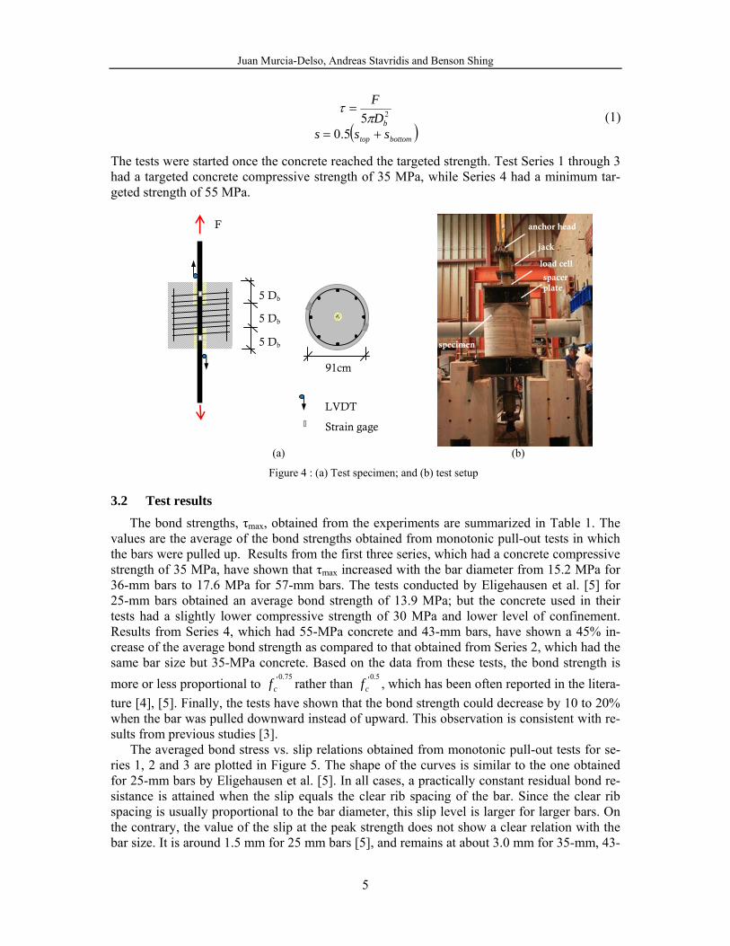
A typical test specimen and the test setup are shown in Figure 4. Each specimen consisted of a reinforcing bar embedded in a 3-ft.-diameter concrete cylinder with an embedment length equal to 5 times the bar diameter ( bD ). The bar was bonded only in the central portion of the cylinder, and ungrouted PVC tubes were used to create unbonded zones in the upper and lower regions of the concrete cylinder to minimize any local disturbance to the bonded zone during the loading process. The test setup was designed to allow the bar to be pulled upwards or downwards using two center-hole hydraulic jacks, one at each end. A threaded T-head was used to anchor the bar at each end. The bar was pulled out from the concrete cylinder when one of the hydraulic jacks pushed against the adjacent anchor head. This was a self-reacting system; thus, the concrete was subjected to compression while the bar was being pulled out. During the test, the pull-out force was measured with a load cell and confirmed with strain gages attached to two opposite sides of the bar near each end of the concrete cylinder; and bar slips were measured at both ends by two linear potentiometers at each end mounted on two opposite sides of the bar. The local bond stress (τ ) vs. slip (s) relation was obtained as the av-erage bond stress vs. the average of the slip at the two ends of the bonded portion,
tops and bottoms . These slip values are calculated as the average of the slips measured at the two linear potentiometers with the bar deformation on the loaded side between the attachment point of the pair of linear potentiometers and the end of bonded zone taken out. The bar de-formation was calculated from strain-gage readings.
Juan Murcia-Delso, Andreas Stavridis and Benson Shing
5
( )bottomtop
bsss
DF
+=
=
5.05 2π
τ (1)
The tests were started once the concrete reached the targeted strength. Test Series 1 through 3 had a targeted concrete compressive strength of 35 MPa, while Series 4 had a minimum tar-geted strength of 55 MPa.
(a) (b)
Figure 4 : (a) Test specimen; and (b) test setup
3.2 Test results
The bond strengths, τmax, obtained from the experiments are summarized in Table 1. The values are the average of the bond strengths obtained from monotonic pull-out tests in which the bars were pulled up. Results from the first three series, which had a concrete compressive strength of 35 MPa, have shown that τmax increased with the bar diameter from 15.2 MPa for 36-mm bars to 17.6 MPa for 57-mm bars. The tests conducted by Eligehausen et al. [5] for 25-mm bars obtained an average bond strength of 13.9 MPa; but the concrete used in their tests had a slightly lower compressive strength of 30 MPa and lower level of confinement. Results from Series 4, which had 55-MPa concrete and 43-mm bars, have shown a 45% in-crease of the average bond strength as compared to that obtained from Series 2, which had the same bar size but 35-MPa concrete. Based on the data from these tests, the bond strength is more or less proportional to
75.0'cf rather than
5.0'cf , which has been often reported in the litera-
ture [4], [5]. Finally, the tests have shown that the bond strength could decrease by 10 to 20% when the bar was pulled downward instead of upward. This observation is consistent with re-sults from previous studies [3].
The averaged bond stress vs. slip relations obtained from monotonic pull-out tests for se-ries 1, 2 and 3 are plotted in Figure 5. The shape of the curves is similar to the one obtained for 25-mm bars by Eligehausen et al. [5]. In all cases, a practically constant residual bond re-sistance is attained when the slip equals the clear rib spacing of the bar. Since the clear rib spacing is usually proportional to the bar diameter, this slip level is larger for larger bars. On the contrary, the value of the slip at the peak strength does not show a clear relation with the bar size. It is around 1.5 mm for 25 mm bars [5], and remains at about 3.0 mm for 35-mm, 43-
anchor head
spacer plate
specimen
load cell
jack
LVDT
Strain gage
5 Db
5 Db
5 Db
91cm
F
Juan Murcia-Delso, Andreas Stavridis and Benson Shing
6
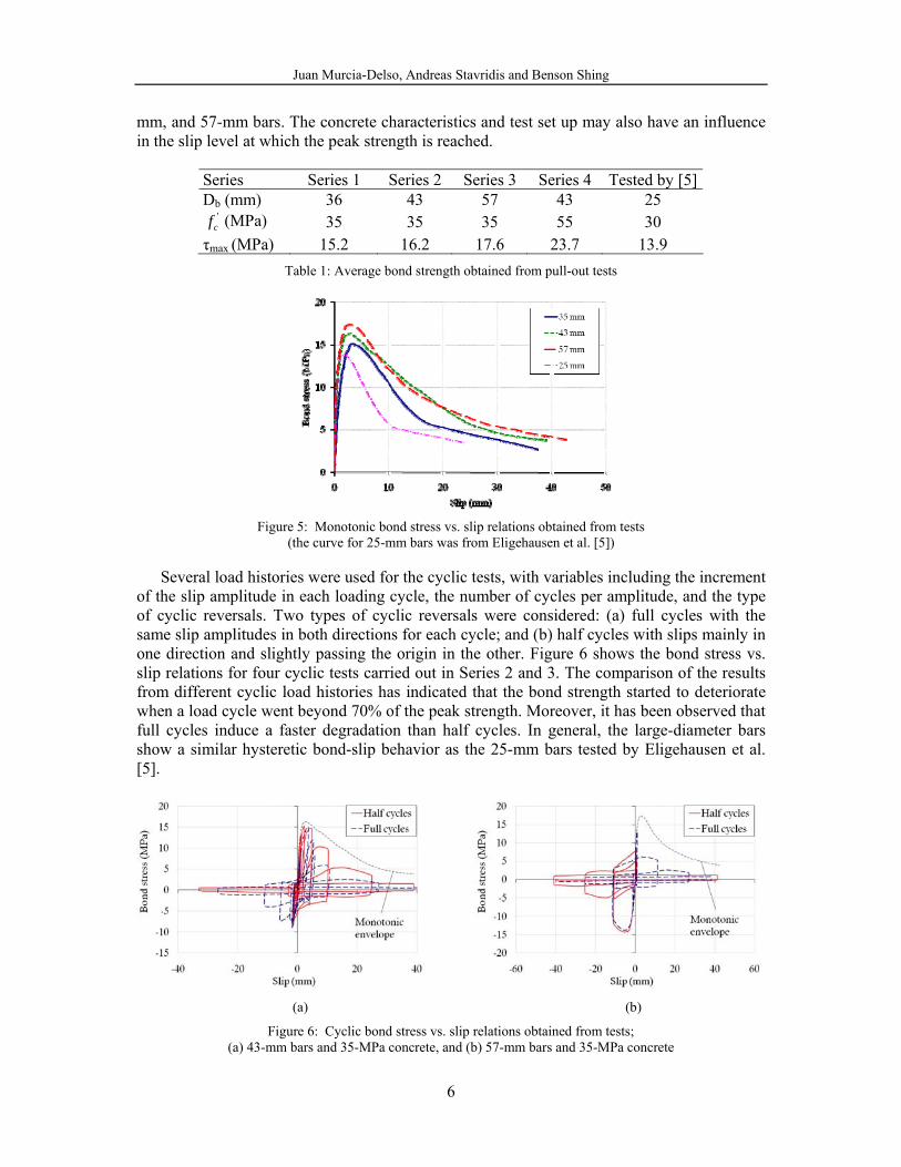
mm, and 57-mm bars. The concrete characteristics and test set up may also have an influence in the slip level at which the peak strength is reached.
Series Series 1 Series 2 Series 3 Series 4 Tested by [5] Db (mm) 36 43 57 43 25
'cf (MPa) 35 35 35 55 30
τmax (MPa) 15.2 16.2 17.6 23.7 13.9 Table 1: Average bond strength obtained from pull-out tests
Figure 5: Monotonic bond stress vs. slip relations obtained from tests
(the curve for 25-mm bars was from Eligehausen et al. [5])
Several load histories were used for the cyclic tests, with variables including the increment of the slip amplitude in each loading cycle, the number of cycles per amplitude, and the type of cyclic reversals. Two types of cyclic reversals were considered: (a) full cycles with the same slip amplitudes in both directions for each cycle; and (b) half cycles with slips mainly in one direction and slightly passing the origin in the other. Figure 6 shows the bond stress vs. slip relations for four cyclic tests carried out in Series 2 and 3. The comparison of the results from different cyclic load histories has indicated that the bond strength started to deteriorate when a load cycle went beyond 70% of the peak strength. Moreover, it has been observed that full cycles induce a faster degradation than half cycles. In general, the large-diameter bars show a similar hysteretic bond-slip behavior as the 25-mm bars tested by Eligehausen et al. [5].
(a) (b)
Figure 6: Cyclic bond stress vs. slip relations obtained from tests; (a) 43-mm bars and 35-MPa concrete, and (b) 57-mm bars and 35-MPa concrete
Juan Murcia-Delso, Andreas Stavridis and Benson Shing
7
4 BOND-SLIP LAW FOR CONFINED BARS
A phenomenological bond-slip model for bars embedded in well-confined concrete has been developed based on the experimental data presented in the previous section. The model is similar to the ones proposed in [5] and [6] but has a more general bond-slip law. For mono-tonic loading, the bond stress is defined as a function of the slip by means of simple polyno-mial functions. This law is extended to cyclic loading by scaling down the monotonic envelope using damage parameters that depend on the slip history to account for cyclic bond degradation. The main difference with previous models is that the degradation of the envelope curve is governed by two damage parameters presenting the degradations of the bearing resis-tance and friction resistance, respectively. In addition, the model is more general in that it can be used for different bar sizes and concrete types with the calibration of only three parameters.
4.1 Bond-slip law for monotonic loading
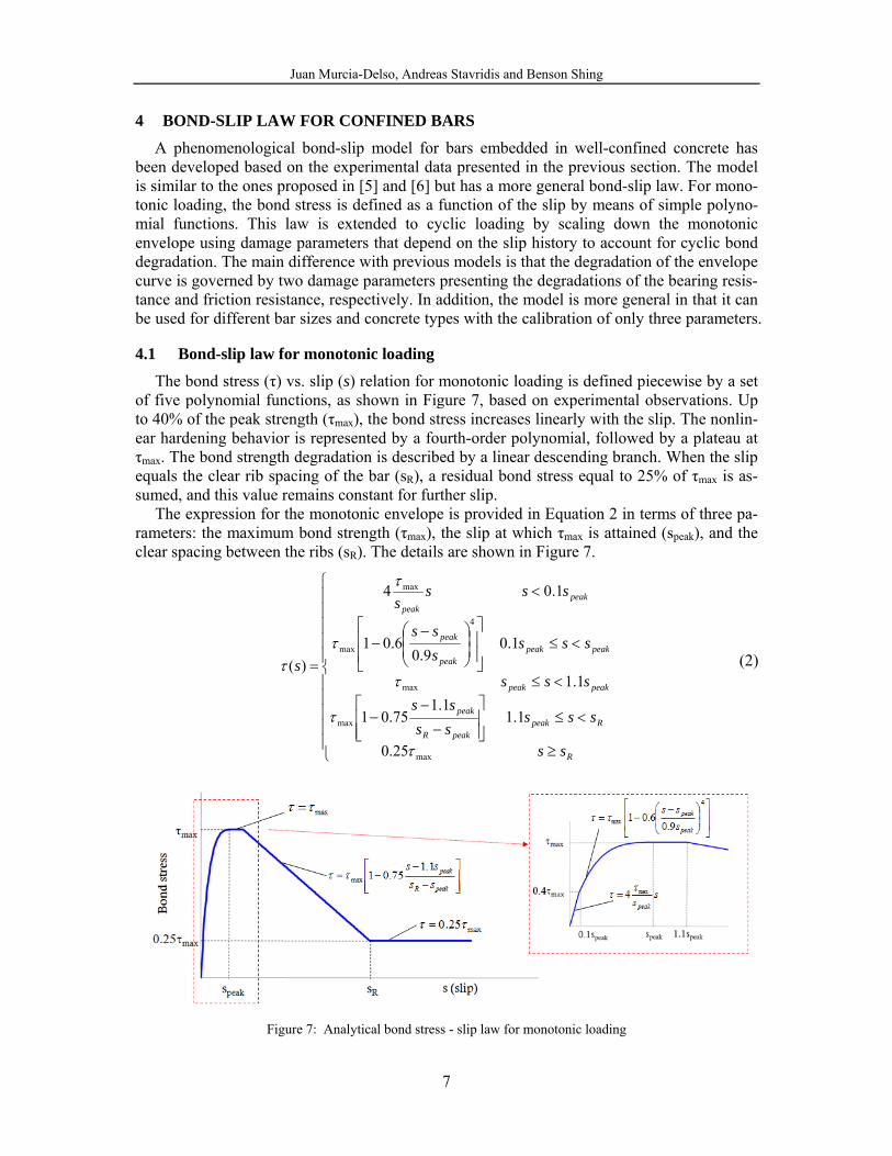
The bond stress (τ) vs. slip (s) relation for monotonic loading is defined piecewise by a set of five polynomial functions, as shown in Figure 7, based on experimental observations. Up to 40% of the peak strength (τmax), the bond stress increases linearly with the slip. The nonlin-ear hardening behavior is represented by a fourth-order polynomial, followed by a plateau at τmax. The bond strength degradation is described by a linear descending branch. When the slip equals the clear rib spacing of the bar (sR), a residual bond stress equal to 25% of τmax is as-sumed, and this value remains constant for further slip.
The expression for the monotonic envelope is provided in Equation 2 in terms of three pa-rameters: the maximum bond strength (τmax), the slip at which τmax is attained (speak), and the clear spacing between the ribs (sR). The details are shown in Figure 7.
⎪⎪⎪⎪⎪
⎩
⎪⎪⎪⎪⎪
⎨
⎧
≥
<≤⎥⎥⎦
⎤
⎢⎢⎣
⎡
−
−−
<≤
<≤⎥⎥
⎦
⎤
⎢⎢
⎣
⎡
⎟⎟⎠
⎞⎜⎜⎝
⎛ −−
<
=
R
RpeakpeakR
peak
peakpeak
peakpeakpeak
peak
peakpeak
ss
sssssss
sss
ssssss
ssss
s
max
max
max
4
max
max
25.0
1.11.1
75.01
1.1
1.09.0
6.01
1.04
)(
τ
τ
τ
τ
τ
τ (2)
Figure 7: Analytical bond stress - slip law for monotonic loading
Juan Murcia-Delso, Andreas Stavridis and Benson Shing
8
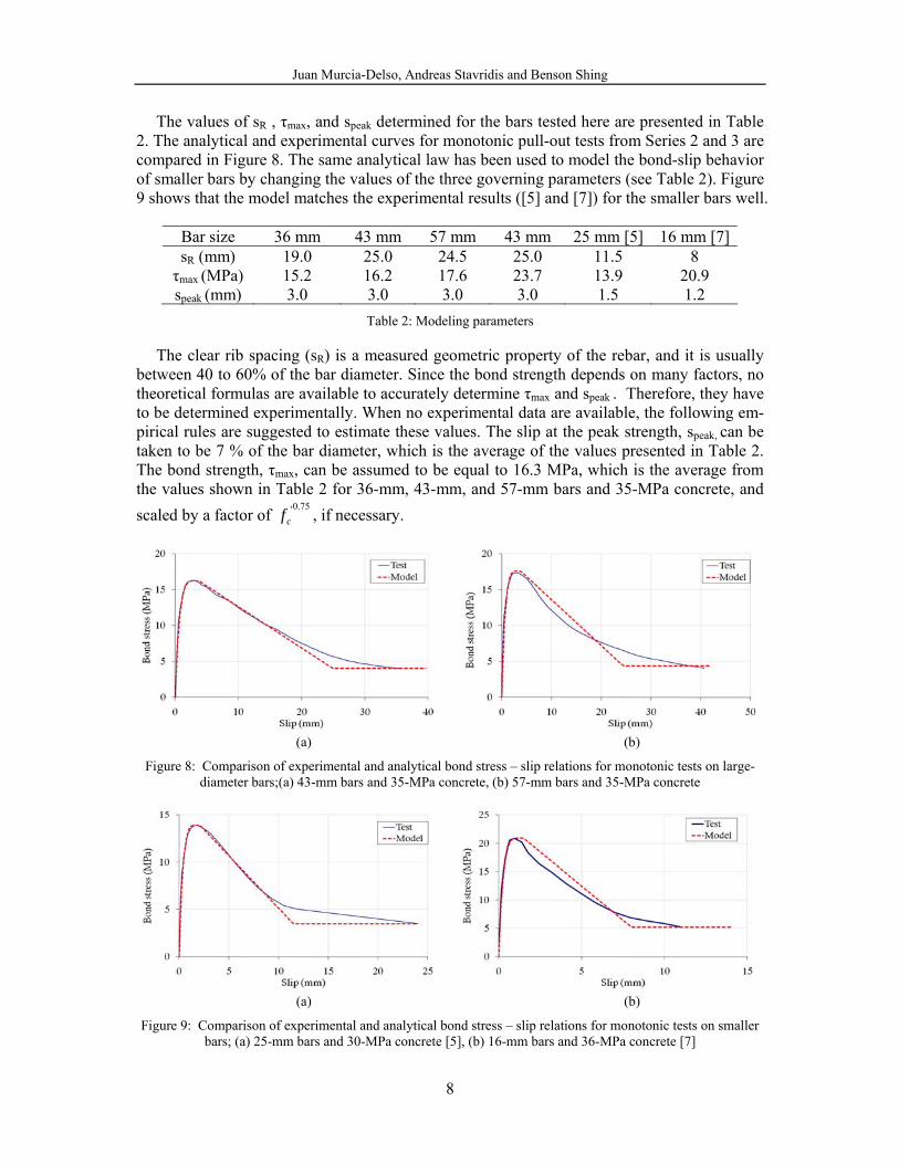
The values of sR , τmax, and speak determined for the bars tested here are presented in Table 2. The analytical and experimental curves for monotonic pull-out tests from Series 2 and 3 are compared in Figure 8. The same analytical law has been used to model the bond-slip behavior of smaller bars by changing the values of the three governing parameters (see Table 2). Figure 9 shows that the model matches the experimental results ([5] and [7]) for the smaller bars well.
Bar size 36 mm 43 mm 57 mm 43 mm 25 mm [5] 16 mm [7]sR (mm) 19.0 25.0 24.5 25.0 11.5 8 τmax (MPa) 15.2 16.2 17.6 23.7 13.9 20.9 speak (mm) 3.0 3.0 3.0 3.0 1.5 1.2
Table 2: Modeling parameters
The clear rib spacing (sR) is a measured geometric property of the rebar, and it is usually between 40 to 60% of the bar diameter. Since the bond strength depends on many factors, no theoretical formulas are available to accurately determine τmax and speak . Therefore, they have to be determined experimentally. When no experimental data are available, the following em-pirical rules are suggested to estimate these values. The slip at the peak strength, speak, can be taken to be 7 % of the bar diameter, which is the average of the values presented in Table 2. The bond strength, τmax, can be assumed to be equal to 16.3 MPa, which is the average from the values shown in Table 2 for 36-mm, 43-mm, and 57-mm bars and 35-MPa concrete, and scaled by a factor of
75.0'cf , if necessary.
(a) (b)
Figure 8: Comparison of experimental and analytical bond stress – slip relations for monotonic tests on large-diameter bars;(a) 43-mm bars and 35-MPa concrete, (b) 57-mm bars and 35-MPa concrete
(a) (b)
Figure 9: Comparison of experimental and analytical bond stress – slip relations for monotonic tests on smaller bars; (a) 25-mm bars and 30-MPa concrete [5], (b) 16-mm bars and 36-MPa concrete [7]
Juan Murcia-Delso, Andreas Stavridis and Benson Shing
9
4.2 Bond-slip law for cyclic loading
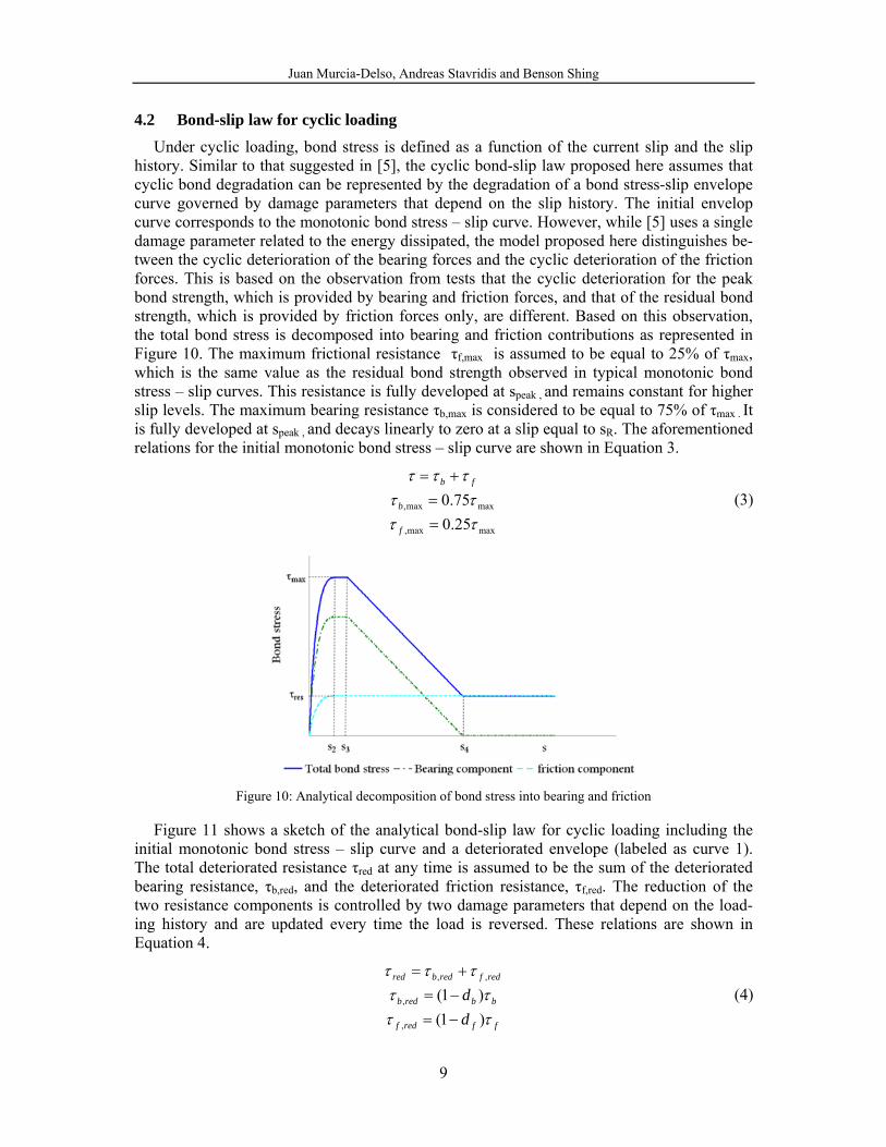
Under cyclic loading, bond stress is defined as a function of the current slip and the slip history. Similar to that suggested in [5], the cyclic bond-slip law proposed here assumes that cyclic bond degradation can be represented by the degradation of a bond stress-slip envelope curve governed by damage parameters that depend on the slip history. The initial envelop curve corresponds to the monotonic bond stress – slip curve. However, while [5] uses a single damage parameter related to the energy dissipated, the model proposed here distinguishes be-tween the cyclic deterioration of the bearing forces and the cyclic deterioration of the friction forces. This is based on the observation from tests that the cyclic deterioration for the peak bond strength, which is provided by bearing and friction forces, and that of the residual bond strength, which is provided by friction forces only, are different. Based on this observation, the total bond stress is decomposed into bearing and friction contributions as represented in Figure 10. The maximum frictional resistance τf,max is assumed to be equal to 25% of τmax, which is the same value as the residual bond strength observed in typical monotonic bond stress – slip curves. This resistance is fully developed at speak , and remains constant for higher slip levels. The maximum bearing resistance τb,max is considered to be equal to 75% of τmax . It is fully developed at speak , and decays linearly to zero at a slip equal to sR. The aforementioned relations for the initial monotonic bond stress – slip curve are shown in Equation 3.
maxmax,
maxmax,
25.075.0τττττττ
==
+=
f
b
fb
(3)
Figure 10: Analytical decomposition of bond stress into bearing and friction
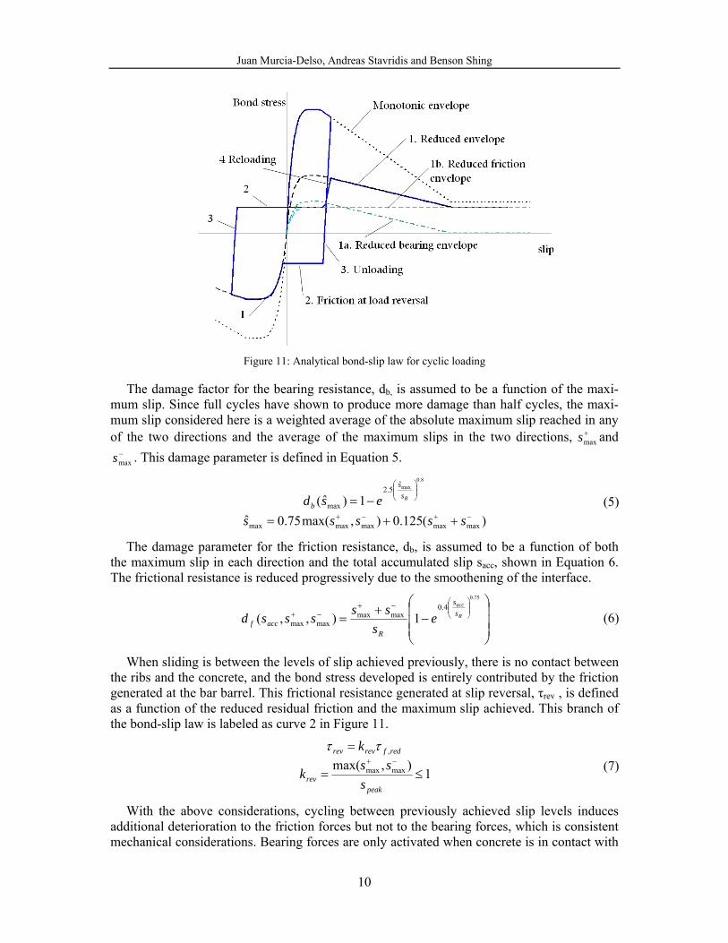
Figure 11 shows a sketch of the analytical bond-slip law for cyclic loading including the initial monotonic bond stress – slip curve and a deteriorated envelope (labeled as curve 1). The total deteriorated resistance τred at any time is assumed to be the sum of the deteriorated bearing resistance, τb,red, and the deteriorated friction resistance, τf,red. The reduction of the two resistance components is controlled by two damage parameters that depend on the load-ing history and are updated every time the load is reversed. These relations are shown in Equation 4.
ffredf
bbredb
redfredbred
dd
ττττ
τττ
)1()1(
,
,
,,
−=−=+=
(4)
Juan Murcia-Delso, Andreas Stavridis and Benson Shing
10
Figure 11: Analytical bond-slip law for cyclic loading
The damage factor for the bearing resistance, db, is assumed to be a function of the maxi-mum slip. Since full cycles have shown to produce more damage than half cycles, the maxi-mum slip considered here is a weighted average of the absolute maximum slip reached in any of the two directions and the average of the maximum slips in the two directions, +
maxs and −maxs . This damage parameter is defined in Equation 5.
)(125.0),max(75.0ˆ
1)ˆ(
maxmaxmaxmaxmax
ˆ5.2
max
8.0max
−+−+
⎟⎟⎠
⎞⎜⎜⎝
⎛
++=−=
sssssesd Rs
s
b (5)
The damage parameter for the friction resistance, db, is assumed to be a function of both the maximum slip in each direction and the total accumulated slip sacc, shown in Equation 6. The frictional resistance is reduced progressively due to the smoothening of the interface.
⎟⎟⎟
⎠
⎞
⎜⎜⎜
⎝
⎛−
+=
⎟⎟⎠
⎞⎜⎜⎝
⎛−+−+
75.0
4.0maxmax
maxmax 1),,( R
acc
ss
Raccf e
ssssssd (6)
When sliding is between the levels of slip achieved previously, there is no contact between the ribs and the concrete, and the bond stress developed is entirely contributed by the friction generated at the bar barrel. This frictional resistance generated at slip reversal, τrev , is defined as a function of the reduced residual friction and the maximum slip achieved. This branch of the bond-slip law is labeled as curve 2 in Figure 11.
1),max( maxmax
,
≤=
=−+
peakrev
redfrevrev
sssk
k ττ (7)
With the above considerations, cycling between previously achieved slip levels induces additional deterioration to the friction forces but not to the bearing forces, which is consistent mechanical considerations. Bearing forces are only activated when concrete is in contact with
Juan Murcia-Delso, Andreas Stavridis and Benson Shing
11
the ribs, and this happens for slip levels exceeding previously reached values. Deterioration of the bearing forces is caused by crushing and shearing of concrete in front of the ribs.
To fully define the cyclic law, unloading and reloading rules need to be specified. Upon slip reversal, bond stress decreases linearly until τrev is achieved. This branch of the bond-slip law is labeled as curve 3 in Figure 11. For the reloading branch, labeled as curve 4 in Figure 11, the stress increases linearly from τrev until the reduced envelope is reached. Both unload-ing and reloading stiffnesses are equal to the initial stiffness of the monotonic bond stress -
slip curve: peaks
k max4 τ= .
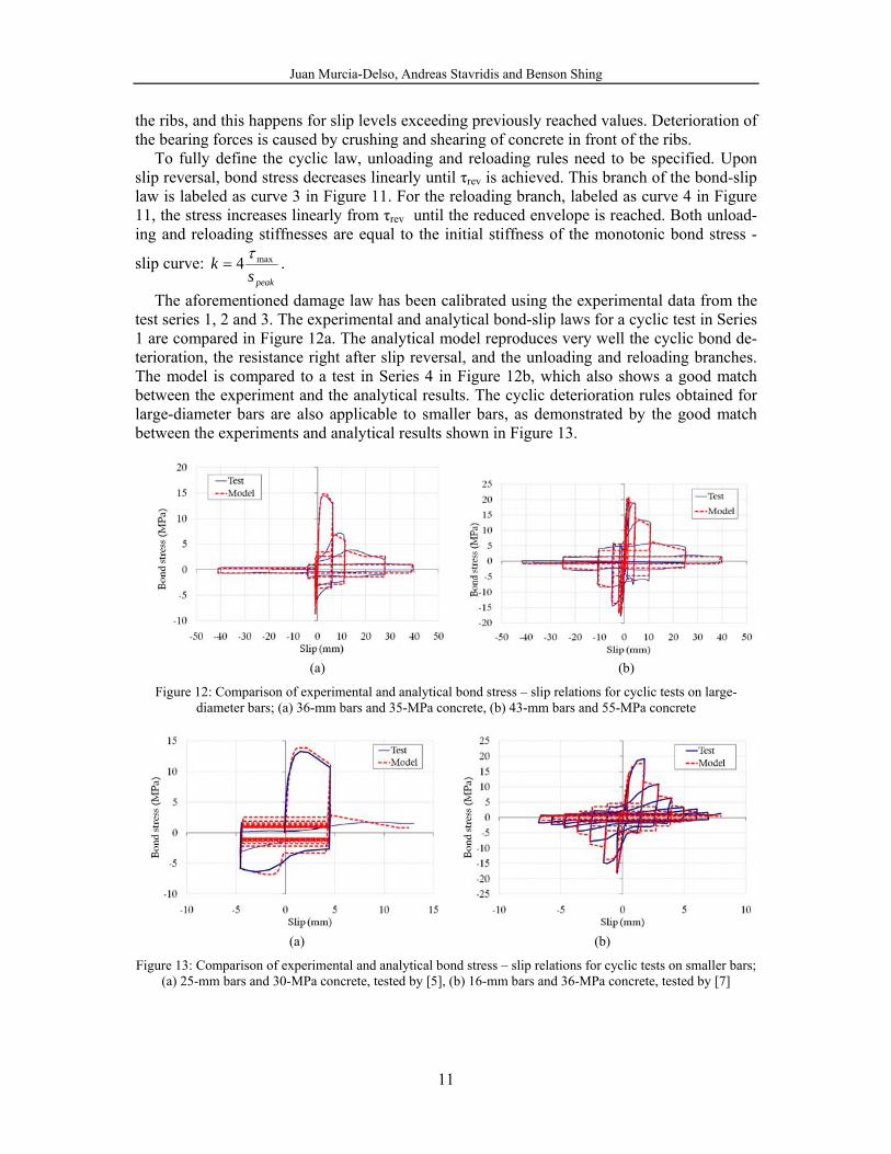
The aforementioned damage law has been calibrated using the experimental data from the test series 1, 2 and 3. The experimental and analytical bond-slip laws for a cyclic test in Series 1 are compared in Figure 12a. The analytical model reproduces very well the cyclic bond de-terioration, the resistance right after slip reversal, and the unloading and reloading branches. The model is compared to a test in Series 4 in Figure 12b, which also shows a good match between the experiment and the analytical results. The cyclic deterioration rules obtained for large-diameter bars are also applicable to smaller bars, as demonstrated by the good match between the experiments and analytical results shown in Figure 13.
(a) (b)
Figure 12: Comparison of experimental and analytical bond stress – slip relations for cyclic tests on large-diameter bars; (a) 36-mm bars and 35-MPa concrete, (b) 43-mm bars and 55-MPa concrete
(a) (b) Figure 13: Comparison of experimental and analytical bond stress – slip relations for cyclic tests on smaller bars;
(a) 25-mm bars and 30-MPa concrete, tested by [5], (b) 16-mm bars and 36-MPa concrete, tested by [7]
Juan Murcia-Delso, Andreas Stavridis and Benson Shing
12
5 FINITE ELEMENT ANALYSIS APPLICATION
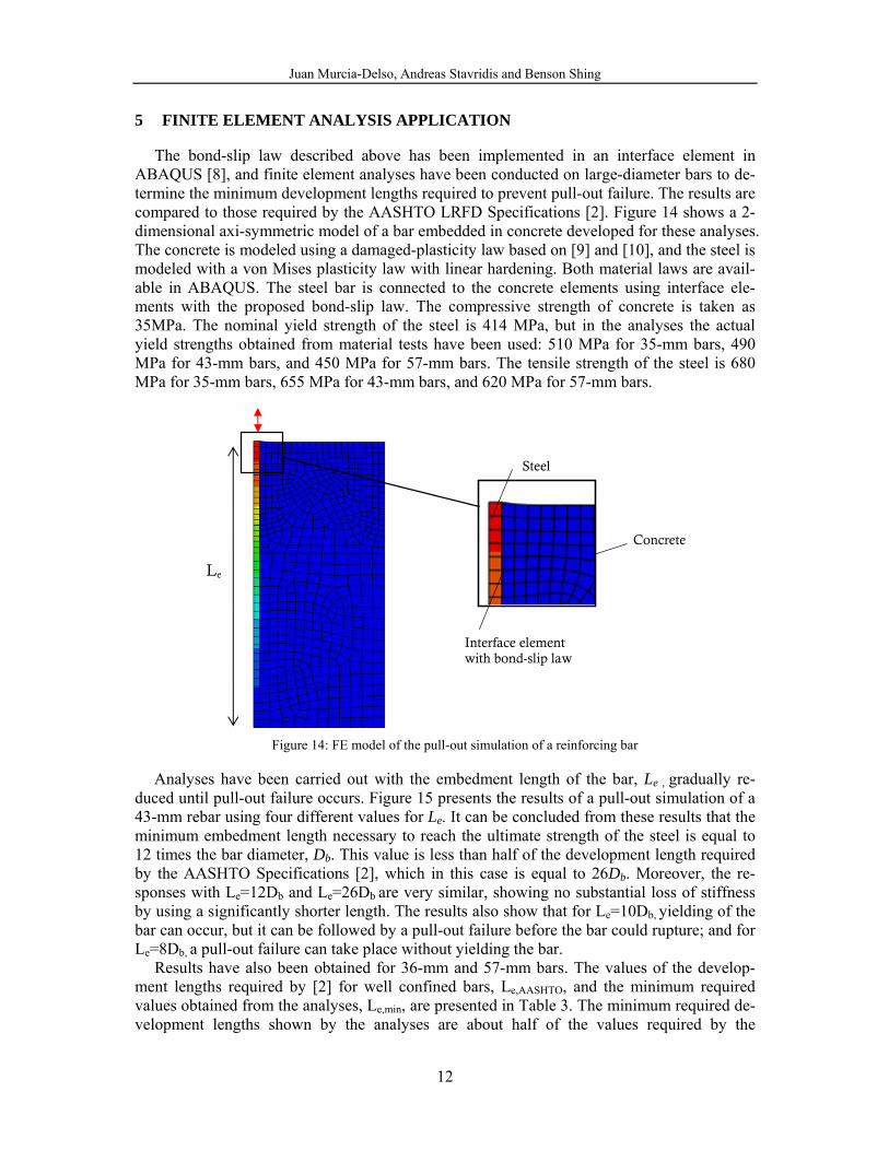
The bond-slip law described above has been implemented in an interface element in ABAQUS [8], and finite element analyses have been conducted on large-diameter bars to de-termine the minimum development lengths required to prevent pull-out failure. The results are compared to those required by the AASHTO LRFD Specifications [2]. Figure 14 shows a 2-dimensional axi-symmetric model of a bar embedded in concrete developed for these analyses. The concrete is modeled using a damaged-plasticity law based on [9] and [10], and the steel is modeled with a von Mises plasticity law with linear hardening. Both material laws are avail-able in ABAQUS. The steel bar is connected to the concrete elements using interface ele-ments with the proposed bond-slip law. The compressive strength of concrete is taken as 35MPa. The nominal yield strength of the steel is 414 MPa, but in the analyses the actual yield strengths obtained from material tests have been used: 510 MPa for 35-mm bars, 490 MPa for 43-mm bars, and 450 MPa for 57-mm bars. The tensile strength of the steel is 680 MPa for 35-mm bars, 655 MPa for 43-mm bars, and 620 MPa for 57-mm bars.
Figure 14: FE model of the pull-out simulation of a reinforcing bar
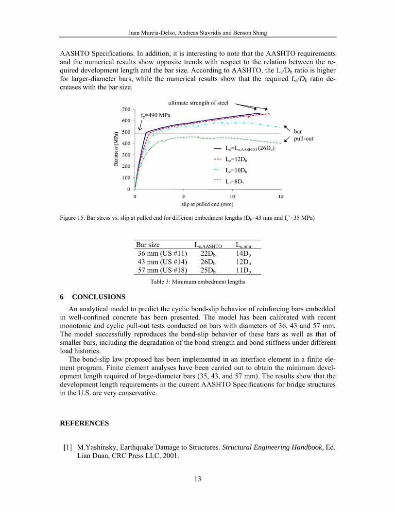
Analyses have been carried out with the embedment length of the bar, Le , gradually re-duced until pull-out failure occurs. Figure 15 presents the results of a pull-out simulation of a 43-mm rebar using four different values for Le. It can be concluded from these results that the minimum embedment length necessary to reach the ultimate strength of the steel is equal to 12 times the bar diameter, Db. This value is less than half of the development length required by the AASHTO Specifications [2], which in this case is equal to 26Db. Moreover, the re-sponses with Le=12Db and Le=26Db are very similar, showing no substantial loss of stiffness by using a significantly shorter length. The results also show that for Le=10Db, yielding of the bar can occur, but it can be followed by a pull-out failure before the bar could rupture; and for Le=8Db, a pull-out failure can take place without yielding the bar.
Results have also been obtained for 36-mm and 57-mm bars. The values of the develop-ment lengths required by [2] for well confined bars, Le,AASHTO, and the minimum required values obtained from the analyses, Le,min, are presented in Table 3. The minimum required de-velopment lengths shown by the analyses are about half of the values required by the
Steel
Concrete
Interface element with bond-slip law
Le
Juan Murcia-Delso, Andreas Stavridis and Benson Shing
13
AASHTO Specifications. In addition, it is interesting to note that the AASHTO requirements and the numerical results show opposite trends with respect to the relation between the re-quired development length and the bar size. According to AASHTO, the Le/Db ratio is higher for larger-diameter bars, while the numerical results show that the required Le/Db ratio de-creases with the bar size.
Figure 15: Bar stress vs. slip at pulled end for different embedment lengths (Db=43 mm and fc’=35 MPa)
Bar size Le,AASHTO Le,min 36 mm (US #11) 22Db 14Db 43 mm (US #14) 26Db 12Db 57 mm (US #18) 25Db 11Db
Table 3: Minimum embedment lengths
6 CONCLUSIONS
An analytical model to predict the cyclic bond-slip behavior of reinforcing bars embedded in well-confined concrete has been presented. The model has been calibrated with recent monotonic and cyclic pull-out tests conducted on bars with diameters of 36, 43 and 57 mm. The model successfully reproduces the bond-slip behavior of these bars as well as that of smaller bars, including the degradation of the bond strength and bond stiffness under different load histories.
The bond-slip law proposed has been implemented in an interface element in a finite ele-ment program. Finite element analyses have been carried out to obtain the minimum devel-opment length required of large-diameter bars (35, 43, and 57 mm). The results show that the development length requirements in the current AASHTO Specifications for bridge structures in the U.S. are very conservative.
REFERENCES
[1] M.Yashinsky, Earthquake Damage to Structures. Structural Engineering Handbook, Ed. Lian Duan, CRC Press LLC, 2001.
Le=Le,AASHTO (26Db)
Le=12Db
Le=10Db
Le=8Db
ultimate strength of steel
bar pull-out
fy=490 MPa
Juan Murcia-Delso, Andreas Stavridis and Benson Shing
14
[2] American Association of State Highway and Transportation Officials (AASHTO), LRFD Bridge Design Specifications, 5th Edition, 2010.
[3] Fédération internationale du béton (fib), fib bulletin 10: Bond of reinforcement in con-crete, Task group bond model, Lausanne, 2000.
[4] American Concrete Institute (ACI) Committee 408, Bond and Development of Straight Reinforcing Bars in Tension, ACI-408R-03, 2003.
[5] R. Eligehausen, E.G. Popov, V.V. Bertero, Local bond stress - slip relationships of de-formed bars under generalized excitations, UCB-EERC, 1983.
[6] L.N., Lowes, J.P. Moehle, S. Govindjee, Concrete-Steel Bond Model for Use in Finite Element Modeling of Reinforced Concrete Structures. ACI Structural Journal, 101-S50, 2004.
[7] K. Lundgren, Pull-out tests of steel-encased specimens subjected to reversed cyclic loading. Materials and Structures, 33-231, 450-456, 2000.
[8] Dassault Systemes, Abaqus Analysis User’s Manual Version 6.9, 2009.
[9] J. Lubliner, J. Oliver, S. Oller, E. Oñate, A plastic-damage model for concrete. Int. J. Solids Structures, 25, 299-326, 1989.
[10] J. Lee, G.L. Fenves, A plastic-damage concrete model for earthquake analysis of dams. Earthquake Engineering and Structural Dynamics, 27, 937-956, 1998.


![SEISMIC RETROFIT OF EXISTING STEEL MOMENT RESISTING …congress.cimne.com/eccomas/proceedings/compdyn2011/compdyn2011_full/... · 351 [4] and FEMA 547 [5]).Because MRFs are more flexible](https://img.pdfslide.net/doc/110x75/5e0e6653b7492f145e0ebdb1/seismic-retrofit-of-existing-steel-moment-resisting-351-4-and-fema-547-5because.jpg)