Embed Size (px)
Citation preview

Research ArticleModeling the Mechanical Consequences ofAge-Related Trabecular Bone Loss by XFEM Simulation
Ruoxun Fan,1,2 He Gong,1 Xianbin Zhang,1 Jun Liu,3 Zhengbin Jia,1 and Dong Zhu4
1Department of Engineering Mechanics, Jilin University, Nanling Campus, Changchun 130025, China2Department of Automobile and Construction Engineering, Beihua University, Jilin 132013, China3Hand & Foot Surgery and Reparative & Reconstructive Surgery Center, No. 2 Hospital of Jilin University, Changchun 130025, China4Department of Traumatic Orthopedics, The First Hospital of Jilin University, Changchun 130025, China
Correspondence should be addressed to He Gong; [email protected] and Dong Zhu; [email protected]
Received 18 January 2016; Accepted 23 May 2016
Academic Editor: Thierry Busso
Copyright © 2016 Ruoxun Fan et al. This is an open access article distributed under the Creative Commons Attribution License,which permits unrestricted use, distribution, and reproduction in any medium, provided the original work is properly cited.
The elderly are more likely to suffer from fracture because of age-related trabecular bone loss. Different bone loss locations andpatterns have different effects on bone mechanical properties. Extended finite element method (XFEM) can simulate fractureprocess and was suited to investigate the effects of bone loss on trabecular bone. Age-related bone loss is indicated by trabecularthinning and loss andmay occur at low-strain locations or other random sites. Accordingly, several ideal normal and aged trabecularbone models were created based on different bone loss locations and patterns; then, fracture processes from crack initiation tocomplete failure of these models were observed by XFEM; finally, the effects of different locations and patterns on trabecular bonewere compared. Results indicated that bone loss occurring at low-strain locationswasmore detrimental to trabecular bone than thatoccurring at other random sites; meanwhile, the decrease in bone strength caused by trabecular loss was higher than that caused bytrabecular thinning, and the effects of vertical trabecular loss onmechanical properties weremore severe than horizontal trabecularloss.This study provided a numerical method to simulate trabecular bone fracture and distinguished different effects of the possibleoccurrence of bone loss locations and patterns on trabecular bone.
1. Introduction
Given rapid increase in the elderly population, age-relatedfracture has become an important public health issue [1,2]. Many reasons explain why the elderly are susceptibleto fracture; however, the main reason is the decreasedbone strength caused by age-related trabecular bone loss[3, 4]. Investigating the effects of trabecular bone loss onthe mechanical properties of bone structure may thereforeassist in understanding the bone degeneration and fracturemechanism, which is meaningful for preventing age-relatedosteoporosis and fractures.
Age-related changes in the microstructure of trabecularbone, such as decrease in trabecular thickness and loss oftrabecular connectivity, may decrease bone volume fraction(BV/TV) and weaken bone microstructure [3, 5]. Given thattrabecular bone contributes significantly to bone mechan-ical integrity and determines bone quality, the effects of
age-related changes in trabecular bone on its mechanicalproperties have been investigated [6–8]. Trabecular numberand thickness decreasewith age, and the related bone strengthdecreases by 34% to 47% among the elderly [7]. In thelumbar spine, rod-like trabeculae become thinner with ageand finally disappear, thereby causing a discontinuity in themicrostructure [8]. In the femoral head, changes occur inthe form of a simultaneous thinning and perforation of theplate-like trabeculae, which lead to new and relatively thinnerplates and rods [9]. All these changes constitute the keyfactors that contribute to the age-related fracture. In addition,trabecular connectivity may also have an important role inmaintaining bone strength, but the connectivity inevitablydecreases with age, which in turn increases the risk of fracturefor the elderly [10].
Since significant relationship between age-related chan-ges in trabecular microstructure and its fracture risk hasbeen found, it is therefore important to understand the
Hindawi Publishing CorporationComputational and Mathematical Methods in MedicineVolume 2016, Article ID 3495152, 12 pageshttp://dx.doi.org/10.1155/2016/3495152

2 Computational and Mathematical Methods in Medicine
effects of such changes on the mechanical properties oftrabecular bone [11, 12]. To investigate the effects of variousarchitectural deterioration factors on fracture characteristics,many studies focused on quantifying and comparing themorphological parameters of aged trabecular bones basedon microcomputed tomography (micro-CT) images [5, 13].However, in order to fully understand the effects of age-related changes, it is not sufficient to merely compare themorphological parameters for aged specimens. The degener-ation process of trabecular bone with respect to trabeculaetype and microstructure should also be investigated. Withthe development of structure modeling technique, severalmethods in modeling trabeculae microstructure were putforward. Individual trabecula segmentation technique, whichcan decompose the trabecular bone network into individualtrabecular plates and rods, was developed [14, 15];meanwhile,a method for subdividing a trabecular network into hori-zontal and vertical oriented trabeculae was also put forward[8]. Although the type and orientation of trabeculae canbe distinguished using above methods, it is also difficult toidentify the changes in actual aged trabecular microstructurecompared with the normal one. For example, bone loss loca-tions and patterns in actual aged trabecular microstructuresmay not be determined. Instead, ideal trabecular bonemodel,which could artificially produce different bone loss locationsand patterns for aged trabecular bone models based on theactual degeneration process, can solve this problem [6, 16].Thus, ideal trabecular bone model can serve as a promisingmodel to investigate the age-related changes in trabecularbone microstructure [17, 18].
In addition, finite element (FE) method has become ahighly efficient technique to estimate bone strength andfracture risk [1, 19]. Several FE methods based on fractureanalysis could accurately simulate the fracture process, suchas the element deletion techniqueand the cohesive zone ele-ments [20, 21]. As a new method of fracture analysis, XFEMcan simulate whole fracture process from crack initiationto complete failure more conveniently because its fractureprocess is independent of mesh and does not require defininga crack-extension path in advance; meanwhile, a quantityof simulative results obtained through XFEM analysis areconsistent with the experimental data [19, 22, 23].
Accordingly, this study aimed to simulate the fractureprocesses of ideal trabecular bone models based on XFEManalysis. Several ideal normal and aged trabecular bonemodels were first created based on different bone losslocations and patterns, and then the effects of these differ-ent locations and patterns of age-related bone loss on themechanical properties of trabecular bone were compared.These simulations may assist in explaining the age-relatedfracture mechanism by analyzing the variations in trabecularmicrostructure and provide a theoretical basis for preventionof age-related fracture.
2. Materials and Methods
2.1. Construction of Trabecular BoneModels. Trabecular boneis composed of trabeculae in the form of rods and plates, andtrabecular bone microstructure may vary across anatomical
locations [9, 24]. Accordingly, two ideal normal trabecularbone models (Model-rod A and Model-plate A) were firstcreated [18, 25–27] (Figure 1). The trabecular bone tissuematerial was assumed to be isotropic with the elasticmodulusof 12GPa and Poisson’s ratio of 0.3 [20, 28].
Aging may result in trabecular bone loss at two typesof regions: random sites and low-strain locations [6, 16, 29].Here trabecular bone loss at random sites was defined asdegeneration location 1, and trabecular bone loss at low-strainlocations was defined as degeneration location 2. Meanwhile,the process of age-related trabecular bone loss is formed intwo steps. For rod-like structures, trabecular rods at the twodegenerated regions initially became thinner, after which partof these thinner rods were resorbed (Figure 2(a)); given thesechanges, BV/TV decreased by 15%–20% [9, 30]. For plate-likestructures, trabecular plates at the two degenerated regionsinitially became thinner, after which part of these thinnerplates were perforated (Figure 2(b)); given these changes,BV/TV decreased by 25%–30% [10, 31]. Therefore, two agedrod-like and plate-like models in the two degenerationlocations were established. First, based on Model-rod A,thickness of the rod-like trabeculae decreased at random sitesand at low-strain locations; a number of breakages were thenproduced in part of the abovementioned thinner rods. As aresult, two aged rod-like models (Model-rod B and Model-rod C) were created. For these two aged models, BV/TVdecreased by 15% relative to that of Model-rod A. Similarly,based onModel-plateA, plate-like trabeculae became thinnerat random sites and at low-strain locations; a number ofthese thinner trabecular plates then exhibited perforations.As such, two aged plate-like models (Model-plate B andModel-plate C) were created. For these two aged models,BV/TV decreased by 25% relative to that of Model-plate A.
Regardless of the locationswhere trabeculaewere lost, theprocess of age-related bone loss includes two steps: thinningof the trabecula and eventual loss [3, 16, 32]. BV/TVdecreasessignificantly due to trabecular thinning. Trabecular loss haslittle effect on BV/TV, but it decreases the connectivity oftrabecular bone to a great extent. It was unknown whethertrabecular thinning would bring severer effects on trabecularbone than trabecular loss in terms of damage and fracture.Thus, it was necessary to compare the relative effects oftrabecular thinning and loss on the mechanical propertiesof trabecular bone. Here trabecular loss was subdivided intoloss of trabeculae along the vertical and horizontal directions.Therefore, three degeneration patterns were considered: thin-ning of trabecula was defined as degeneration pattern 1; lossof vertical trabecula was defined as degeneration pattern2; loss of horizontal trabecula was defined as degenerationpattern 3. Based on the normal models (Model-rod A andModel-plate A), three sets of rod-like and plate-like modelswith different degeneration patterns were created: (1) Asshown in Figure 3(a), Model-rod D and Model-plate D withdegeneration pattern 1 were created by uniformly reducingthe thickness of trabeculae from the normal models. (2)As shown in Figure 3(b), a quantity of vertical trabecularelements were randomly removed from the normal models,which formed Model-rod E and Model-plate E with degen-eration pattern 2. (3) As shown in Figure 3(c), a quantity of

Computational and Mathematical Methods in Medicine 3
(a) (b)
Figure 1: Two ideal normal rod-like and plate-like trabecular bone models were created. (a) Model-rod A with BV/TV of 10.29%. (b) Model-plate A with BV/TV of 27.69%.
(a) (b)
Figure 2: The process of age-related bone loss includes two steps: thinning of the trabecula and its eventual loss. The two-step degenerationprocess for single rod-like and plate-like trabecular bone cells was shown, respectively. (a) Degeneration process of the rod-like cell: trabecularrods at the two degenerated regions initially became thinner, after which part of these thinner rods were broken. (b) Degeneration processof the plate-like cell: trabecular plates at the two degenerated regions became thinner gradually; then part of these thinner trabecular plateswere perforated.
horizontal trabecular elements were randomly removed fromthe normal models, which formed Model-rod F and Model-plate F with degeneration pattern 3. It was difficult to reducetoomuch BV/TV through loss of trabeculae alone. Given thatthe mechanical properties were obviously changed by at leasta 5% reduction in BV/TV [16, 33], approximate 8% reductionin the original BV/TV of normalmodels was simulated for allthe different degeneration pattern models.
2.2. Fracture Simulation Based on XFEM. The fracture pro-cess of trabecular bone structure is generally controlled bystrain-based criterion, and both of the tissue yield and crackinitiation strains are asymmetric in tension and compression[34–36]. Thus in this paper “Cast Iron Plasticity” modelin ABAQUS was used to simulate the asymmetric tensile-compressive tissue yielding. When the tensile or compressiveprincipal strain in the FE model exceeded the tensile orcompressive tissue yield strain, the postyield tissue elasticmodulus was set to 5% of the initial elastic modulus [37,38]. In this study, it was assumed that trabecular bonematerial entered tensile yield stage when its tensile principalstrain reached 0.33%, and the tensile crack was initiatedwhen the tensile principal strain exceeded 0.61% and thattrabecular bone material entered compressive yield stage
when its compressive principal strain reached 0.81%, andthe compressive crack was initiated when the compressiveprincipal strain exceeded 1.02% [19, 20, 39].
Although compressive strain may occasionally introducebreakage [40], for XFEM there is no crack initiation criterionin compression in ABAQUS.The subroutine UDMGINI wastherefore compiled to embed the compressive crack initiationcriterion in this study. Therefore, when either tensile orcompressive crack initiation strain in the FE model wasexceeded, crack would be initiated, and the new introducedcrack was normal to the principal strain direction [23].
Once crack initiation condition was met, crack began togrow obeying bone damage propagation law. The energy-based criterion was selected in damage evolution, and theenergy release rates of trabecular bone tissue were all set to0.33N/mm [19, 41]. All the models were compressed underdisplacement-control loading. An apparent strain of 5% wasimposed on the top surface of the model, and the bottomsurface of the model was constrained. Meanwhile, in thisstudy the average normal and aged trabecular thicknesseswere 140 𝜇m and 126 𝜇m [5, 30]. Therefore, considering themesh sensitivity analysis and solution convergence [38], theaverage mesh size of 35 𝜇m was selected, and eight-nodehexahedron C3D8 element was used.

4 Computational and Mathematical Methods in Medicine
(a) (b)
(c)
Figure 3: Three degeneration patterns in the ideal trabecular bone models were shown. (a) Degeneration pattern 1: thinning of trabeculae,which were simulated by uniformly reducing the trabecular thickness from the normal models. (b) Degeneration pattern 2: loss of verticaltrabeculae, which were simulated by randomly removing the vertical trabecular elements from the normal models. (c) Degeneration pattern3: loss of horizontal trabeculae, which were simulated by randomly removing the horizontal trabecular elements from the normal models.
2.3. Validation Experiments. To validate the method in mod-eling ideal trabecular bone and XFEM analysis used in thisstudy, four rapid prototype (RP) models of Model-rod Aand four RP models of Model-plate A were manufactured,respectively, by RP laser sinterstation (SLS 2500 Plus, DTMCorporation, USA). Due to the limitation of sinterstationresolution, each edge of the ideal normal trabecular bonemodel was scaled up by 10 times so that trabecular featuresin the RP models can be observed (Figure 4(a)). Polyamide-12 powder was used as the raw material to manufacture theRP models, and the energy density of the sintering laser wasset to 0.016 J/mm2 [42, 43]. Then compressive mechanicaltests were conducted on these RP models to compare theapparent stress-strain curves and fracture patterns withXFEM simulation for the corresponding Model-rod A andModel-plate A. Here the XFEM simulation was the samewith the abovementioned process, and it was assigned withpolyamide-12 material instead of trabecular bone material.The elastic modulus of polyamide-12 was set to 1300MPa,Poisson’s ratio was set to 0.3, and yield and crack initiationstrains were set to 1.5% and 10%, respectively [44–46].
3. Results
3.1. Validation of the Ideal FE Models and XFEM Analy-sis. Comparison of the deformations and fracture patternsbetween the trabecular FE models and the correspondingRP models was shown in Figures 4(b) and 4(c). Becauseall the RP models were regular, the fracture processes andpatterns under compression were nearly the same for the RPmodels with the same microarchitecture. It can be seen thatfractures in both the FEmodels and RPmodels with the samemicroarchitecture appeared at the similar sites, which were atthe intersections between vertical and horizontal trabeculae.Figure 5 shows the comparison of the apparent stress-straincurves predicted by the XFEM analysis for normal FEmodelsand those obtained by the compressive tests for the cor-responding RP models. Here the experimentally measuredcurves for the RP models with the same microarchitecturewere averaged since no obvious differences in each curveof the same four RP models were observed. Not only didthe predicted stress-strain curves show the same orders ofmagnitude in fracture strain, that is, the percentage differencebetween the simulated and experimentallymeasured fracture

Computational and Mathematical Methods in Medicine 5
(a) (b)
(c)
Figure 4: Comparison of the deformations and fracture patterns predicted by the XFEM analysis and those obtained by compressive testsfor the corresponding RP models. (a) RP models of Model-rod A andModel-plate A were manufactured by RP laser sinterstation. Each edgeof the normal trabecular bone model was scaled up by 10 times in these RP models. (b) The front view of deformations and fracture patternsfor the RP models, and the fracture sites were marked by black circle. (c) The front view of fracture contour plots for the FE models.
0 2 4 6 8 100
2
4
6
8
10
Rod-like RP modelRod-like FE model
Appa
rent
stre
ss (M
Pa)
Apparent strain (%)
(a)
0 3 6 9 12 150
10
20
30
40
50
Plate-like RP modelPlate-like FE model
Appa
rent
stre
ss (M
Pa)
Apparent strain (%)
(b)
Figure 5: Comparison ofthe apparent stress-strain curves predicted byXFEManalysis forModel-rodA andModel-plateA and those obtainedby compressive tests for the corresponding rod-like and plate-like RP models. The experimentally measured curves for the RP models withthe same microarchitecture were averaged since no obvious differences in each curve of the same four RP models were observed.
strains was less than 8%, but the similar patterns for thecurve shapes and onsets of fracture between simulation andexperiment were also observed. Thus, these comparisonsshowed the reliability of the method in modeling idealtrabecular bone and the XFEM analysis used in this studycould accurately simulate the experimental results.
3.2. Effects of Different Degeneration Locations on Fracturesof Rod-Like Models. The apparent stress-strain curves of thethree rod-like models were shown in Figure 6(a). Model-rodA had the highest apparent fracture strain and ultimate stress,Model-rod C was the lowest, and Model-rod B was betweenthose two. Regardless of the locations where trabeculae were
6 Computational and Mathematical Methods in Medicine
0.0 0.6 1.2 1.8 2.4 3.00
1
2
3
4
5
Model-rod AModel-rod BModel-rod C
Appa
rent
stre
ss (M
Pa)
Apparent strain (%)
A
B
C
D
E
(a)STATUSXFEM(Avg: 75%)
+1.000e + 00
+9.167e − 01
+8.333e − 01
+7.500e − 01
+6.667e − 01
+5.833e − 01
+5.000e − 01
+4.167e − 01
+3.333e − 01
+2.500e − 01
+1.667e − 01
+8.333e − 02
+0.000e + 00
+1.000e + 00
+9.167e − 01
+8.333e − 01
+7.500e − 01
+6.667e − 01
+5.833e − 01
+5.000e − 01
+4.167e − 01
+3.333e − 01
+2.500e − 01
+1.667e − 01
+8.333e − 02
+0.000e + 00
STATUSXFEM(Avg: 75%)
Position (A) Position (C)
Position (D)Position (E)
(b)
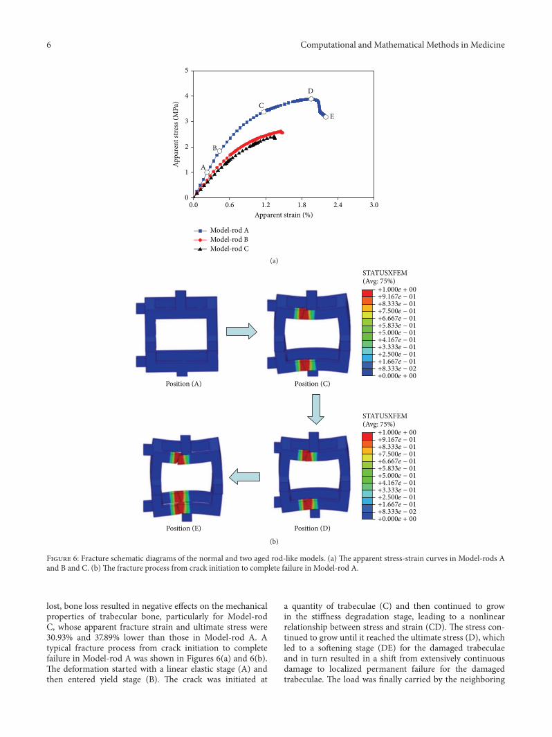
Figure 6: Fracture schematic diagrams of the normal and two aged rod-like models. (a) The apparent stress-strain curves in Model-rods Aand B and C. (b) The fracture process from crack initiation to complete failure in Model-rod A.
lost, bone loss resulted in negative effects on the mechanicalproperties of trabecular bone, particularly for Model-rodC, whose apparent fracture strain and ultimate stress were30.93% and 37.89% lower than those in Model-rod A. Atypical fracture process from crack initiation to completefailure in Model-rod A was shown in Figures 6(a) and 6(b).The deformation started with a linear elastic stage (A) andthen entered yield stage (B). The crack was initiated at
a quantity of trabeculae (C) and then continued to growin the stiffness degradation stage, leading to a nonlinearrelationship between stress and strain (CD). The stress con-tinued to grow until it reached the ultimate stress (D), whichled to a softening stage (DE) for the damaged trabeculaeand in turn resulted in a shift from extensively continuousdamage to localized permanent failure for the damagedtrabeculae. The load was finally carried by the neighboring

Computational and Mathematical Methods in Medicine 7
0.0 0.6 1.2 1.8 2.4 3.00
4
8
12
16
20
Model-plate AModel-plate BModel-plate C
Appa
rent
stre
ss (M
Pa)
Apparent strain (%)
(a)
STATUSXFEM(Avg: 75%)
+1.000e + 00
+9.167e − 01
+8.333e − 01
+7.500e − 01
+6.667e − 01
+5.833e − 01
+5.000e − 01
+4.167e − 01
+3.333e − 01
+2.500e − 01
+1.667e − 01
+8.333e − 02
+0.000e + 00
STATUSXFEM(Avg: 75%)
+1.000e + 00
+9.167e − 01
+8.333e − 01
+7.500e − 01
+6.667e − 01
+5.833e − 01
+5.000e − 01
+4.167e − 01
+3.333e − 01
+2.500e − 01
+1.667e − 01
+8.333e − 02
+0.000e + 00
(b)
Figure 7: Fracture schematic diagrams of the normal and two aged plate-like models. (a) The apparent stress-strain curves in Model-platesA and B and C. (b) The fracture process from crack initiation to complete failure in Model-plate A.
normal trabeculae, instead of the trabeculae that experiencedlocalized permanent failure, until the complete fracture of thetrabecular bone structure (E).
3.3. Effects of Different Degeneration Locations on Fracturesof Plate-Like Models. The apparent stress-strain curves ofthe three plate-like models were shown in Figure 7(a). Thehighest apparent fracture strain was observed in Model-plate
A (i.e., 2.79%) and the fracture strains of Model-plates Band C were 2.31% and 1.61%, respectively. The apparentultimate stress also decreased significantly with deterioratedstructures, decreasing from 14.36MPa in Model-plate A to8.41MPa and 5.48MPa inModel-plates B and C, respectively.The fracture process from crack initiation to complete failurein Model-plate A was shown in Figure 7(b). When crack ini-tiation condition was met, a small crack was generated in the

8 Computational and Mathematical Methods in Medicine
15
12
9
6
3
0
Ulti
mat
e stre
ss (M
Pa)
Mod
el-r
od D
Mod
el-r
od E
Mod
el-r
od F
Mod
el-p
late
D
Mod
el-p
late
E
Mod
el-p
late
F
(a)
3
2.4
1.8
1.2
0.6
0
Frac
ture
stra
in (%
)
Mod
el-r
od D
Mod
el-r
od E
Mod
el-r
od F
Mod
el-p
late
D
Mod
el-p
late
E
Mod
el-p
late
F
(b)
Figure 8: Apparent ultimate stresses and fracture strains of rod-like models and plate-like models in the three degeneration patterns.
plate-like trabecula. With increasing strain, the crack startedto grow inside the trabecula along horizontal direction, untilcomplete fracture of the trabecular bone structure occurred.
3.4. Effects of Different Degeneration Patterns on Fracture.Different trabecular bone degeneration patterns caused bytrabecular thinning or loss both led to decrease in themechanical properties of normal trabecular bone models,whereas the mechanical properties were more sensitive totrabecular loss than to trabecular thinning; furthermore, themechanical properties of trabecular bonewere less affected byloss of horizontal trabeculae than by loss of vertical trabeculae(Figure 8). For the trabecular loss models, the localizedfracture sites were all close to the disconnected trabeculae(Figure 9).
4. Discussion
This study utilized a numerical simulation method to predictthe fracture processes in normal and aged trabecular bonemodels. The fractures of these models were simulated usingXFEM analysis embedded subroutine UDMGINI, in whichthe principal strains in tension and compression were used tocontrol the crack initiation and propagation. In the simula-tion process, when the principal strain in the aged trabecularbone model exceeded the crack initiation strain of trabecularbone tissue, crack in the aged model would be initiated,and then the crack began to grow obeying the bone damagepropagation law until complete fracture occurred in theaged model. According to the XFEM analyses in this study,different fracture processes from crack initiation to completefailure for the aged trabecular bone models were primarilyobserved; then, apparent ultimate stress and fracture strainof the aged trabecular bone models were obtained, and themechanical properties of different aged trabecular bonemod-els were compared; finally, the effects of bone degenerationlocations and patterns on the mechanical properties of agedtrabecular bone models were analyzed quantitatively.
At present, many numerical methods can simulate crackinitiation and propagation of bone structure [21, 47, 48].Compared with these methods, XFEM can obtain detailed
fracture information at localized damage sites. Becauseapparent fracture begins with localized damage, investigatingthe mechanical characteristics at localized damage sites canassist in exploring the mechanism of fracture [13]. For othermethods, however, analyzing localized damage of trabeculaeat tissue level remains difficult because of the limitation ofcalculation principle.
In this study, the apparent fracture strain of Model-rodA was 1.94%, and that of Model-plate A was 2.79%. Thesewere consistent with the previous investigation, which showsthat the apparent fracture strains are 2% and 2.7% in thenormal rod-like and plate-like trabecular bone models [20].Several experimental results show that the apparent ultimatestress is 3.18MPa in human lumbar spinal trabecular boneand 3.64MPa in proximal tibia trabecular bone, which wereconsistent with our computational results [49, 50]. Mean-while, the aged rod-like models (Model-rods B and C) wereused to represent osteoporotic trabecular bones in this study,and their apparent fracture strains were 1.45% and 1.34%,which were in agreement with the results of compressiveexperiments for the human osteoporotic trabecular bones[51]. All these comparisons showed the accuracy of thepredicted results based on XFEM analysis in this study.
With respect to the roles of rod-like and plate-like tra-beculae in fracture process, rod-like models may participatein initiation and progress of fracture at the sites with lowbone density, which aremore susceptible to large deformationor buckling failure; by contrast, plate-like models may belocated at sites with high bone density, which are most likelyto bear bending loads [27, 33, 52, 53]. Crack initiation andpropagation are correlated with microstructure and BV/TV,and structure model index (SMI) may also be one of the keypredictors [54, 55]. Increasing SMI definitely causes negativeeffects on the mechanical properties of trabecular bone [56].This conclusion was also supported by our results: the frac-ture strain and ultimate stress in the plate-like models wereall higher than those in the rod-like models. Unfortunately,part of trabeculae are inevitably converted from plate-like torod-like forms with age, thereby increasing SMI [3, 10]. Suchchange may be one of the reasons why the elderly are morelikely to suffer from fracture.

Computational and Mathematical Methods in Medicine 9
STATUSXFEM(Avg: 75%)
+1.000e + 00
+9.167e − 01
+8.333e − 01
+7.500e − 01
+6.667e − 01
+5.833e − 01
+5.000e − 01
+4.167e − 01
+3.333e − 01
+2.500e − 01
+1.667e − 01
+8.333e − 02
+0.000e + 00
STATUSXFEM(Avg: 75%)
+1.000e + 00
+9.167e − 01
+8.333e − 01
+7.500e − 01
+6.667e − 01
+5.833e − 01
+5.000e − 01
+4.167e − 01
+3.333e − 01
+2.500e − 01
+1.667e − 01
+8.333e − 02
+0.000e + 00
(a)
STATUSXFEM(Avg: 75%)
+1.000e + 00
+9.167e − 01
+8.333e − 01
+7.500e − 01
+6.667e − 01
+5.833e − 01
+5.000e − 01
+4.167e − 01
+3.333e − 01
+2.500e − 01
+1.667e − 01
+8.333e − 02
+0.000e + 00
STATUSXFEM(Avg: 75%)
+1.000e + 00
+9.167e − 01
+8.333e − 01
+7.500e − 01
+6.667e − 01
+5.833e − 01
+5.000e − 01
+4.167e − 01
+3.333e − 01
+2.500e − 01
+1.667e − 01
+8.333e − 02
+0.000e + 00
(b)
Figure 9: Localized fracture contour plots of trabecular lossmodels. (a) Typical localized fractures presented inModel-rod E andModel-plateE. (b) Typical localized fractures presented in Model-rod F and Model-plate F.
As shown in Figures 6(a) and 7(a), regardless of thetrabecular structures, the lengths of yield stage in the stress-strain curves for the aged models were all shorter thanthose for the corresponding normal models. Moreover, asthe degeneration aggravated, ductile fracture slowly turnedto brittle fracture in aged models. This phenomenon wassupported in literature: advanced glycation end products,which have been reported to alter the formation and prop-agation of damage by making the bone more brittle, areproduced in human bone with age [57]. Thus, final fracturestrains decreased in aged trabecular bone models because ofshorter yield stage, resulting in earlier fracture. In addition,it has been reported that trabeculae at low-strain locations(degeneration location 2) are more likely to be resorbed withage [16]. Combining with our observation, the effects of
degeneration location 2 on trabecular bone were evidentlymore severe than those of degeneration location 1. Therefore,compared with bone loss occurring at the other degenerationlocations, bone loss occurred at degeneration location 2,which is more likely to be resorbed, and had more seriouseffects on the mechanical properties of trabecular bone. Thisphenomenon explained why the elderly were more likely tosuffer from fracture from bone loss mechanism.
Regardless of the locations where trabeculae are lost,age-related bone loss is derived from trabecular thinning orloss. Thus, it is necessary to determine the crucial degener-ation factor by identifying the relative effects of trabecularthinning and loss on mechanical properties. As shown inFigure 8, loss of vertical trabeculae generated the mostserious effects, whichwas in agreementwith the experimental

10 Computational and Mathematical Methods in Medicine
results [58, 59]. Thus, the effects of loss of vertical trabeculaeon trabecular bonewere tremendous, particularly for rod-liketrabecular bone [32]. Given that the load is parallel to the ver-tically oriented trabeculae, vertical trabeculae will bear mostof the load and horizontal trabeculae may act as stabilizingcross-braces, and the vertical trabeculae were therefore morehighly strained than the horizontal trabeculae [8, 58]. If thevertical trabeculae are damaged or resorbed massively, theload carried by the intact vertical trabeculae in the vicinity ofthe damaged vertical trabeculae will increase and accumulaterapidly, which may lead to two consequences. First, if theintact vertical trabeculae in the vicinity of the damaged onespossess large slenderness, the intact vertical trabeculae mayresult in buckling failure. Buckling failure is recognized asrelevant to the failure of the vertebral trabecular bone [33,42]. Second, if the condition of buckling failure is not met,brittle fracture may occur under relatively small strain for thesupporting horizontal trabeculae between two intact verticaltrabeculae. Because vertical trabeculae are lost massively, theloads supported by the remaining vertical trabeculae are toolarge, which may produce too much bending on the cross-bracing horizontal trabecula between them. Both of thesephenomena are consistent with the conclusions that failuresin the vertical trabeculae are predominantly generated bycompressive deformation, whereas failures in the horizontaltrabeculae are predominantly generated by bending [16, 59].Thus, these two consequences may be highly correlated withthe fracture of rod-like trabecular bone structure.
For the plate-like structures, trabecular losswas generatedby resorption cavities, and the connectivity within the struc-ture was not totally lost, so that the load can still be carriedand transmitted, which had better mechanical propertiescompared with rod-like structures [15]. However, this typeof resorption was characterized by a chain effect, wherebystress concentrations in the vicinity of the resorption cavitiesstill caused further damage. Therefore, fracture occurring inthe aged plate-like trabecular bone models was also causedby relatively small loading. These phenomena suggested theimportance of trabecular connectivity in maintaining themechanical properties of trabecular bone, particularly for theintegrity of the vertical trabeculae in rod-like structure.
Several limitations were associated with the ideal tra-becular bone models and simulation process in this study.First, there are some differences in microstructure betweenideal and actual trabecular bone models. Understandingthe effects of different degeneration locations and patternson mechanical properties of trabecular bone was of greatsignificance. However, actual trabecular microstructure isvery complex, which may lead to difficulties in identifyingdifferent degeneration locations or patterns in actual trabec-ular bonemodels. To overcome this problem, ideal trabecularbonemodels were used in this study.These idealmodels allowartificially inducing bone losses which were manufacturedfrom normal models and direct comparison between thenormal and aged models without confounding variationsin tissue properties that are inherent in actual trabecularbones [42, 43]. Although the trabecular bone models wereidealized, all the age-related changes in the microstructurewere developed based on actual degeneration processes, and
all BV/TVswere selected according to literature [3, 5, 9, 10, 27,30]; meanwhile, validation process also showed the reliabilityof the method in modeling ideal trabecular bone (Figures 4and 5). Thus, these two types of models can characterize theessence of the microstructural features of actual trabecularbones. Second, isotropic trabecular bone material was usedbecause the aim of this study was to investigate the effectsof architectural deterioration on the mechanical propertiesof trabecular bone, and modeling trabecular bone tissue asisotropic material may not generate a strong effect on thepredicted results compared with applying anisotropic mate-rial parameters [20, 60]. Finally, the mechanical propertiesof materials that exhibit stiffness degradation and softeningbehavior often lead to severe convergence difficulty [20,22]. Although ABAQUS software provides several viscousparameters to improve the convergence, the convergenceproblem appeared after complete fracture in certain agedmodels occurred. However, it had little effects on the resultsof apparent ultimate stresses and fracture strains.
5. Conclusions
Age-related trabecular bone loss occurring at low-strainlocations was more detrimental to trabecular bone structurethan that occurring at other random sites; meanwhile, thedecrease in trabecular bone strength caused by trabecular losswas higher than that caused by trabecular thinning, and theeffects of vertical trabecular loss on themechanical propertiesof trabecular bone were severer than horizontal trabecularloss.
Competing Interests
The authors declare that there is no conflict of interestsregarding the publication of this paper.
Acknowledgments
Thiswork is supported by theNational Natural Science Foun-dation of China (nos. 11322223, 81471753, and 11432016) andthe Science and Technology Development Plan Foundationof Jilin Province (nos. 20130522059JH and 20160101297JC).
References
[1] E. Dall’Ara, B. Luisier, R. Schmidt, F. Kainberger, P. Zysset, andD. Pahr, “A nonlinear QCT-based finite element model valida-tion study for the human femur tested in two configurations invitro,” Bone, vol. 52, no. 1, pp. 27–38, 2013.
[2] T. Urano and S. Inoue, “Genetics of osteoporosis,” Biochemicaland Biophysical Research Communications, vol. 452, no. 2, pp.287–293, 2014.
[3] W.-Q. Cui, Y.-Y. Won, M.-H. Baek et al., “Age-and region-dependent changes in three-dimensionalmicrostructural prop-erties of proximal femoral trabeculae,” Osteoporosis Interna-tional, vol. 19, no. 11, pp. 1579–1587, 2008.
[4] J. Z. Gao, H. Gong, R. Zhang, and D. Zhu, “Age-relatedregional deterioration patterns and changes in nanoscale char-acterizations of trabeculae in the femoral head,” ExperimentalGerontology, vol. 62, pp. 63–72, 2015.

Computational and Mathematical Methods in Medicine 11
[5] H. Gong, M. Zhang, H. Y. Yeung, and L. Qin, “Regionalvariations in microstructural properties of vertebral trabeculaewith aging,” Journal of Bone andMineralMetabolism, vol. 23, no.2, pp. 174–180, 2005.
[6] J. C. Van Der Linden, J. Homminga, J. A. N. Verhaar, and H.Weinans, “Mechanical consequences of bone loss in cancellousbone,” Journal of Bone and Mineral Research, vol. 16, no. 3, pp.457–465, 2001.
[7] H. M. MacDonald, K. K. Nishiyama, J. Kang, D. A. Hanley, andS. K. Boyd, “Age-related patterns of trabecular and cortical boneloss differ between sexes and skeletal sites: a population-basedHR-pQCT study,” Journal of Bone andMineral Research, vol. 26,no. 1, pp. 50–62, 2011.
[8] J. S. Thomsen, A. S. Niklassen, E. N. Ebbesen, and A. Bruel,“Age-related changes of vertical and horizontal lumbar vertebraltrabecular 3D bone microstructure is different in women andmen,” Bone, vol. 57, no. 1, pp. 47–55, 2013.
[9] M. Stauber and R. Muller, “Age-related changes in trabecularbone microstructures: global and local morphometry,” Osteo-porosis International, vol. 17, no. 4, pp. 616–626, 2006.
[10] H. Chen, X. Zhou, S. Shoumura, S. Emura, and Y. Bunai,“Age-and gender-dependent changes in three-dimensionalmicrostructure of cortical and trabecular bone at the humanfemoral neck,”Osteoporosis International, vol. 21, no. 4, pp. 627–636, 2010.
[11] D.Djonic, P.Milovanovic, S. Nikolic et al., “Inter-sex differencesin structural properties of aging femora: implications on dif-ferential bone fragility: a cadaver study,” Journal of Bone andMineral Metabolism, vol. 29, no. 4, pp. 449–457, 2011.
[12] J. S. Thomsen, E. N. Ebbesen, and L. I. Mosekilde, “Age-relateddifferences between thinning of horizontal and vertical trabec-ulae in human lumbar bone as assessed by a new computerizedmethod,” Bone, vol. 31, no. 1, pp. 136–142, 2002.
[13] J. O. Green, S. Nagaraja, T. Diab, B. Vidakovic, and R. E.Guldberg, “Age-related changes in human trabecular bone:relationship between microstructural stress and strain anddamage morphology,” Journal of Biomechanics, vol. 44, no. 12,pp. 2279–2285, 2011.
[14] J. Wang, B. Zhou, X. S. Liu et al., “Trabecular plates androds determine elastic modulus and yield strength of humantrabecular bone,” Bone, vol. 72, pp. 71–80, 2015.
[15] B. Zhou, X. Sherry Liu, J. Wang, X. Lucas Lu, A. J. Fields,and X. Edward Guo, “Dependence of mechanical propertiesof trabecular bone on plate-rod microstructure determined byindividual trabecula segmentation (ITS),” Journal of Biome-chanics, vol. 47, no. 3, pp. 702–708, 2014.
[16] X. E. Guo and C. H. Kim, “Mechanical consequence of trabec-ular bone loss and its treatment: a three-dimensional modelsimulation,” Bone, vol. 30, no. 2, pp. 404–411, 2002.
[17] S. Vajjala, A. M. Kraynik, and L. J. Gibson, “A cellular solidmodel for modulus reduction due to resorption of trabeculaein bone,” Journal of Biomechanical Engineering, vol. 122, no. 5,pp. 511–515, 2000.
[18] H. Wang, X. S. Liu, B. Zhou et al., “Accuracy of individualtrabecula segmentation based plate and rod finite elementmodels in idealized trabecular bone microstructure,” Journalof Biomechanical Engineering, vol. 135, no. 4, Article ID 44502,2013.
[19] A. A. Ali, L. Cristofolini, E. Schileo et al., “Specimen-specificmodeling of hip fracture pattern and repair,” Journal of Biome-chanics, vol. 47, no. 2, pp. 536–543, 2014.
[20] R. Hambli, “Micro-CT finite element model and experimentalvalidation of trabecular bone damage and fracture,” Bone, vol.56, no. 2, pp. 363–374, 2013.
[21] A. Ural and S. Mischinski, “Multiscale modeling of bonefracture using cohesive finite elements,” Engineering FractureMechanics, vol. 103, pp. 141–152, 2013.
[22] A. A. Abdel-Wahab and V. V. Silberschmidt, “Experimental andnumerical analysis of Izod impact test of cortical bone tissue,”European Physical Journal: Special Topics, vol. 206, no. 1, pp. 41–50, 2012.
[23] E. M. Feerick, X. Y. C. Liu, and P. McGarry, “Anisotropic mode-dependent damage of cortical bone using the extended finiteelement method (XFEM),” Journal of the Mechanical Behaviorof Biomedical Materials, vol. 20, pp. 77–89, 2013.
[24] E. F. Morgan, H. H. Bayraktar, O. C. Yeh, S. Majumdar, A.Burghardt, and T. M. Keaveny, “Contribution of inter-sitevariations in architecture to trabecular bone apparent yieldstrains,” Journal of Biomechanics, vol. 37, no. 9, pp. 1413–1420,2004.
[25] L. J. Gibson, “The mechanical behaviour of cancellous bone,”Journal of Biomechanics, vol. 18, no. 5, pp. 317–328, 1985.
[26] L. J. Gibson, “Biomechanics of cellular solids,” Journal ofBiomechanics, vol. 38, no. 3, pp. 377–399, 2005.
[27] T. Hildebrand, A. Laib, R. Muller, J. Dequeker, and P.Ruegsegger, “Direct three-dimensional morphometric analysisof human cancellous bone: microstructural data from spine,femur, iliac crest, and calcaneus,” Journal of Bone and MineralResearch, vol. 14, no. 7, pp. 1167–1174, 1999.
[28] J. A.Wheeldon, B. D. Stemper, N. Yoganandan, and F. A. Pintar,“Validation of a finite elementmodel of the young normal lowercervical spine,” Annals of Biomedical Engineering, vol. 36, no. 9,pp. 1458–1469, 2008.
[29] J. A. P. Jayasinghe, S. J. Jones, and A. Boyde, “Scanningelectron microscopy of human lumbar vertebral trabecularbone surfaces,” Virchows Archiv A: Pathological Anatomy andHistopathology, vol. 422, no. 1, pp. 25–34, 1993.
[30] H. Chen, S. Shoumura, S. Emura, and Y. Bunai, “Regionalvariations of vertebral trabecular bone microstructure with ageand gender,”Osteoporosis International, vol. 19, no. 10, pp. 1473–1483, 2008.
[31] X. Shi, X. S. Liu, X. Wang, X. E. Guo, and G. L. Niebur,“Type and orientation of yielded trabeculae during overloadingof trabecular bone along orthogonal directions,” Journal ofBiomechanics, vol. 43, no. 13, pp. 2460–2466, 2010.
[32] P. Mc Donnell, N. Harrison, M. A. K. Liebschner, and P. E. McHugh, “Simulation of vertebral trabecular bone loss using voxelfinite element analysis,” Journal of Biomechanics, vol. 42, no. 16,pp. 2789–2796, 2009.
[33] M. J. Silva and L. J. Gibson, “Modeling the mechanical behaviorof vertebral trabecular bone: effects of age-related changes inmicrostructure,” Bone, vol. 21, no. 2, pp. 191–199, 1997.
[34] R. Jungmann, M. E. Szabo, G. Schitter et al., “Local strainand damage mapping in single trabeculae during three-pointbending tests,” Journal of the Mechanical Behavior of BiomedicalMaterials, vol. 4, no. 4, pp. 523–534, 2011.
[35] E. F. Morgan and T. M. Keaveny, “Dependence of yield strainof human trabecular bone on anatomic site,” Journal of Biome-chanics, vol. 34, no. 5, pp. 569–577, 2001.
[36] U. Wolfram, H.-J. Wilke, and P. K. Zysset, “Damage accumula-tion in vertebral trabecular bone depends on loading mode anddirection,” Journal of Biomechanics, vol. 44, no. 6, pp. 1164–1169,2011.

12 Computational and Mathematical Methods in Medicine
[37] H. H. Bayraktar, E. F. Morgan, G. L. Niebur, G. E. Morris, E.K. Wong, and T. M. Keaveny, “Comparison of the elastic andyield properties of human femoral trabecular and cortical bonetissue,” Journal of Biomechanics, vol. 37, no. 1, pp. 27–35, 2004.
[38] G. L. Niebur, M. J. Feldstein, J. C. Yuen, T. J. Chen, and T.M. Keaveny, “High-resolution finite element models with tissuestrength asymmetry accurately predict failure of trabecularbone,” Journal of Biomechanics, vol. 33, no. 12, pp. 1575–1583,2000.
[39] E. Verhulp, B. Van Rietbergen, R. Muller, and R. Huiskes,“Micro-finite element simulation of trabecular-bone post-yieldbehaviour-effects of material model, element size and type,”Computer Methods in Biomechanics and Biomedical Engineer-ing, vol. 11, no. 4, pp. 389–395, 2008.
[40] S. Nagaraja, T. L. Couse, and R. E. Guldberg, “Trabecularbonemicrodamage andmicrostructural stresses under uniaxialcompression,” Journal of Biomechanics, vol. 38, no. 4, pp. 707–716, 2005.
[41] T. L. Norman, S. V. Nivargikar, and D. B. Burr, “Resistance tocrack growth in human cortical bone is greater in shear than intension,” Journal of Biomechanics, vol. 29, no. 8, pp. 1023–1031,1996.
[42] P. McDonnell, N. Harrison, and P. E. McHugh, “Investigation ofthe failure behaviour of vertebral trabecular architectures underuni-axial compression and wedge action loading conditions,”Medical Engineering & Physics, vol. 32, no. 6, pp. 569–576, 2010.
[43] P. Mc Donnell, N. Harrison, S. Lohfeld, O. Kennedy, Y. Zhang,and P. E. McHugh, “Investigation of the mechanical interactionof the trabecular core with an external shell using rapidprototype and finite element models,” Journal of the MechanicalBehavior of Biomedical Materials, vol. 3, no. 1, pp. 63–76, 2010.
[44] B. Caulfield, P. E. McHugh, and S. Lohfeld, “Dependenceof mechanical properties of polyamide components on buildparameters in the SLS process,” Journal of Materials ProcessingTechnology, vol. 182, no. 1–3, pp. 477–488, 2007.
[45] G. V. Salmoria, J. L. Leite, L. F. Vieira, A. T. N. Pires, andC. R.M.Roesler, “Mechanical properties of PA6/PA12 blend specimensprepared by selective laser sintering,” Polymer Testing, vol. 31,no. 3, pp. 411–416, 2012.
[46] T. N. A. T. Rahim, A. M. Abdullah, H. M. Akil, D. Mohamad,and Z. A. Rajion, “Preparation and characterization of a newlydeveloped polyamide composite utilising an affordable 3Dprinter,” Journal of Reinforced Plastics and Composites, vol. 34,no. 19, pp. 1628–1638, 2015.
[47] H. Ridha and P. J. Thurner, “Finite element prediction withexperimental validation of damage distribution in single trabec-ulae during three-point bending tests,” Journal of theMechanicalBehavior of Biomedical Materials, vol. 27, pp. 94–106, 2013.
[48] S. Li, A. Abdel-Wahab, E. Demirci, and V. V. Silberschmidt,“Fracture process in cortical bone: X-FEM analysis ofmicrostructured models,” International Journal of Fracture, vol.184, no. 1-2, pp. 43–55, 2013.
[49] D. L. Kopperdahl and T. M. Keaveny, “Yield strain behavior oftrabecular bone,” Journal of Biomechanics, vol. 31, no. 7, pp. 601–608, 1998.
[50] L. Røhl, E. Larsen, F. Linde, A. Odgaard, and J. Jørgensen, “Ten-sile and compressive properties of cancellous bone,” Journal ofBiomechanics, vol. 24, no. 12, pp. 1143–1149, 1991.
[51] A. C. Vale,M. F. C. Pereira, A.Maurıcio et al., “Micro-computedtomography and compressive characterization of trabecularbone,”Colloids and Surfaces A: Physicochemical and EngineeringAspects, vol. 438, pp. 199–205, 2013.
[52] X. S. Liu, G. Bevill, T. M. Keaveny, P. Sajda, and X. E. Guo,“Micromechanical analyses of vertebral trabecular bone basedon individual trabeculae segmentation of plates and rods,”Journal of Biomechanics, vol. 42, no. 3, pp. 249–256, 2009.
[53] O. C. Yeh and T. M. Keaveny, “Biomechanical effects ofintraspecimen variations in trabecular architecture: a three-dimensional finite element study,” Bone, vol. 25, no. 2, pp. 223–228, 1999.
[54] L. Karim and D. Vashishth, “Role of trabecular microarchitec-ture in the formation, accumulation, andmorphology ofmicro-damage in human cancellous bone,” Journal of OrthopaedicResearch, vol. 29, no. 11, pp. 1739–1744, 2011.
[55] K. Y. Cheuk, T. Y. Zhu, F. W. P. Yu et al., “Abnormal bonemechanical and structural properties in adolescent idiopathicscoliosis: a study with finite element analysis and structuralmodel index,” Calcified Tissue International, vol. 97, no. 4, pp.343–352, 2015.
[56] M. Ding, A. Odgaard, F. Linde, and I. Hvid, “Age-relatedvariations in the microstructure of human tibial cancellousbone,” Journal of Orthopaedic Research, vol. 20, no. 3, pp. 615–621, 2002.
[57] P. Garnero, “The contribution of collagen crosslinks to bonestrength,” BoneKEy Reports, vol. 1, article 182, 2012.
[58] A. J. Fields, G. L. Lee, X. S. Liu, M. G. Jekir, X. E. Guo, and T. M.Keaveny, “Influence of vertical trabeculae on the compressivestrength of the human vertebra,” Journal of Bone and MineralResearch, vol. 26, no. 2, pp. 263–269, 2011.
[59] A. J. Fields and T.M. Keaveny, “Trabecular architecture and ver-tebral fragility in osteoporosis,” Current Osteoporosis Reports,vol. 10, no. 2, pp. 132–140, 2012.
[60] B. Luisier, E. Dall’Ara, and D. H. Pahr, “Orthotropic HR-pQCT-based FE models improve strength predictions for stance butnot for side-way fall loading compared to isotropic QCT-based FE models of human femurs,” Journal of the MechanicalBehavior of Biomedical Materials, vol. 32, pp. 287–299, 2014.