Embed Size (px)
Citation preview
Modeling the response of buried pipes subjected to axial soil movement using coupled finite-discrete element framework Masood Meidani, Mohamed A. Meguid & Luc E. Chouinard Department of Civil Engineering and Applied Mechanics, McGill University Montreal. QC, Canada ABSTRACT The performance of a buried pipe in granular soil subjected to relative axial ground movement is evaluated in this study using a coupled finite-discrete element framework. The pipe is modeled using finite elements (FE) whereas the surrounding soils are modeled using discrete elements (DE). Triangular shaped facet interface elements are used to transfer the contact forces and displacements between the DE and FE domains. Two different pipe materials including a rigid steel pipe and a flexible medium-density polyethylene (MDPE) pipe are modeled. To determine the input parameters needed for each model, calibration is performed using triaxial test data and the microscopic parameters are determined by matching the numerical and experimental results. The particle-induced forces generated on each pipe are calculated and compared with current design guidelines. Results show considerable differences between the common design practice and the numerical results, particularly for pipes installed in the dense sand material. This difference is found to be more significant in rigid steel pipes as compared to flexible MDPE pipes. The detailed behavior of each pipe and the surrounding soil is also investigated based on the coupled FE-DE analysis. It is found that lateral earth pressure is a key factor that affects the soil restraint imposed on the pipe. The proposed coupled FE-DE framework has proven to be effective in investigating this class of soil-pipe interaction problems and capturing the relative movement between the pipe and the surrounding soil. RÉSUMÉ La performance d'un tuyau enterré dans un sol granulaire soumis à un déplacement axial relatif du sol est évaluée dans cette étude en utilisant un cadre d'éléments finis-discrets couplés. Le tube est modélisé à l'aide d'éléments finis (FE) tandis que les sols environnants sont modélisés à l'aide d'éléments discrets (DE). Des éléments d'interface à facettes triangulaires sont utilisés pour transférer les forces de contact et les déplacements entre les domaines DE et FE. Deux matériaux de tuyaux différents, y compris un tuyau en acier rigide et un tuyau flexible en polyéthylène moyenne densité (MDPE) sont modélisés. Pour déterminer les paramètres d'entrée nécessaires pour chaque modèle, l'étalonnage est effectué en utilisant des données de test triaxiaux et les paramètres microscopiques sont déterminés en faisant correspondre les résultats numériques et expérimentaux. Les forces du sol générées sur chaque tuyau sont calculées et comparées aux directives de conception actuelles. Les résultats montrent des différences considérables entre la pratique courante et les résultats numériques, en particulier pour les tuyaux installés dans du sable dense. Cette différence est plus importante pour les tuyaux en acier rigide que pour les tuyaux flexibles en MDPE. Le comportement détaillé de chaque tuyau et du sol environnant est également étudié sur la base de l'analyse FE-DE couplée. On constate que la pression latérale du sol est la principale cause de la contrainte exercée sur le sol par le sol. Le cadre FE-DE couplé proposé s'est avéré efficace pour étudier les problèmes d'interaction tridimensionnels sol-tuyau en capturant le mouvement relatif entre le tuyau et le sol environnant.
1 INTRODUCTION
Pipelines are considered to be safe, efficient and environmentally friendly method to transport oil and natural gas. Canada has more than 840,000 kilometers (km) of transmission and distribution pipelines, of which 119,000 km are buried transmission pipeline. Failure of these infrastructures can have negative effects on the economy, environment, and the public. Incidents such as external interference, corrosion, construction defects and ground movement are known as main reasons of buried
pipeline failure. Permanent ground deformation (PGD) was reported as the fourth cause of failure in the 10th report of European Gas Pipeline Incident data Group (EGIG, 2018). There are many types of ground movement, such as landslide, that imposes extra forces and displacements on these buried structures. The induced strains and stresses in the pipe due to ground movement are function of soil displacement, orientation of pipe axis with respect to the direction of soil movement and the distribution of unstable zones. For instance, if
landslide develops in a direction that is parallel to the pipeline orientation (longitudinal PGD), the entire soil load will be resisted by the pipe axial strains in term of extension or compression.
Soil-pipe interaction mechanisms have been investigated for about half a century using experimental, theoretical, and numerical methods (e.g. Trautmann and O’Rourke, 1983; Konuk et al., 1999; Weerasekara and Wijewickreme, 2008; Robert et al. 2016). These studies involved several simplifying assumptions and limitations. Most of the numerical studies used finite element method (FEM) to model both the pipe and surrounding soil (Daiyan and Kenny, 2011; Roy et al. 2016). Guo and Stolle (2005) report that capturing large soil movements interacting with the buried pipe is hard to achieve using finite element analysis. Also, it is challenging for standard FEM to capture the details of the soil-structure interaction at the particle scale level or close to the pipe-soil interface. On the other hand, the discrete element method (DEM) has proven to be suitable for modeling granular material undergoing large deformations (Tran et al., 2014), however, DEM is not suitable to model the behavior of structural elements due to the continuum behavior of the structure. The coupling of the finite and discrete element methods is a promising approach to study soil-pipe interaction at the microscale level.
This research aims to present a coupled finite-discrete element framework that has been employed to investigate the response of rigid and flexible buried pipes in dense sand subjected to axial ground movement. Finite elements (FE) method is used to model the pipe, while the surrounding soil is created using discrete elements (DE). The input parameters of the DE domain are obtained using a simulated triaxial test following a calibration procedure. Then, the coupled model is validated using experimental data. A brief explanation of the experimental studies used in the validation and the current solution for a pipe buried in granular soil subjected to longitudinal displacement is presented followed by a short description of the numerical framework used in the analysis. The results of the numerical simulation are compared with the recommendations of the ASCE guidelines with emphasis on the limitations for both the rigid and flexible pipe.
2 EXPERIMENTAL STUDY
Two experimental studies have been used in this research for numerical simulation validation. First, Karimian (2006) performed a series of axial pullout tests on rigid steel pipes buried in dense Fraser River Sand. It was found that, during the pullout test, the entire length of the pipe started to move and the peak axial load was achieved at an axial displacement of around 9 mm. Table
1 presents the details of this experiments. The second experiment related to the axial pullout tests of flexible MDPE pipes buried in dense Fraser River Sand have been done by Weerasekara (2007). The study showed that the response of the MDPE pipe is different from rigid steel pipe and significant elongations occur during the pullout test. The test details are summarized in Table 1.
Table 1. Details of the experimental tests
Properties Karimian (2006)
Weerasekara (2007)
Pipe Material Steel MDPE Pipe initial Young’s modulus (Pa) 2E11 5.5E8
Pipe outer diameter, D (mm) 460 114
Pipe length, L (m) 3.8 3.8
Pipe wall thickness, t (mm) 13 10.3
Burial depth, H (m) 1.1 0.6 Pipe stiffness factor, EI / r3 (kN/m) 8.1E6 1.7E4
Backfill material Fraser River sand, Dr = 75%
The general configuration of the numerical simulation
for each pipe material is based on the above mentioned experimental studies. The pipe was installed in the dense backfill material, then the pipe was pulled out in a displacement control approach until convergence of the pullout force is reached.
3 COUPLED FINITE-DISCRETE ELEMENT FRAMEWORK
The presented coupled FE-DE framework in this research is based on the work of Dang and Meguid (2010, 2013). They used an open source discrete element program named YADE (Kozicki and donze, 2009; Smilauer et al., 2010) as a platform to develop the framework. The following sections explain an algorithm of each domain briefly.
3.1 Discrete elements
Discrete element method consists of a group of particles where interactions are modeled as a dynamic process to reach the balance between internal and external forces. Cundall’s linear elastic-plastic law is used as the contact law between the particles considering traction, compression, bending and twisting between the particles. The main microscopic input parameters of this contact model are 𝐸 , the particle modulus; 𝐾 and 𝐾 , the normal and tangential stiffness at the contact point; 𝛽 , the rolling
resistance coefficient; ∅ , the microscopic friction angle of particles, and 𝜂 , which is a dimensionless coefficient to define a threshold for the resistant moment. More details on the contact law can be found in Meidani et al. (2017).
3.2 Finite elements
A dynamic relaxation method is employed to solve the equations of the FE domain. The general equation is: 𝐾 𝑿 𝑐𝑀𝑿 𝑀 𝑿 𝑷 1
where 𝐾 is the stiffness matrix, 𝑐 is the damping coefficient for the mass proportional damping, 𝑀 is the mass matrix, 𝑃 is the external force vector and 𝑿 represents the displacement vector.
In order to satisfy the convergence condition, the time step ∆𝑡 is determined using the maximum eigenvalue:
∆𝑡 ∆𝑡 2𝜆 2
where, 𝜆 is the maximum eigenvalue:
𝜆 max 𝑘𝑀 3
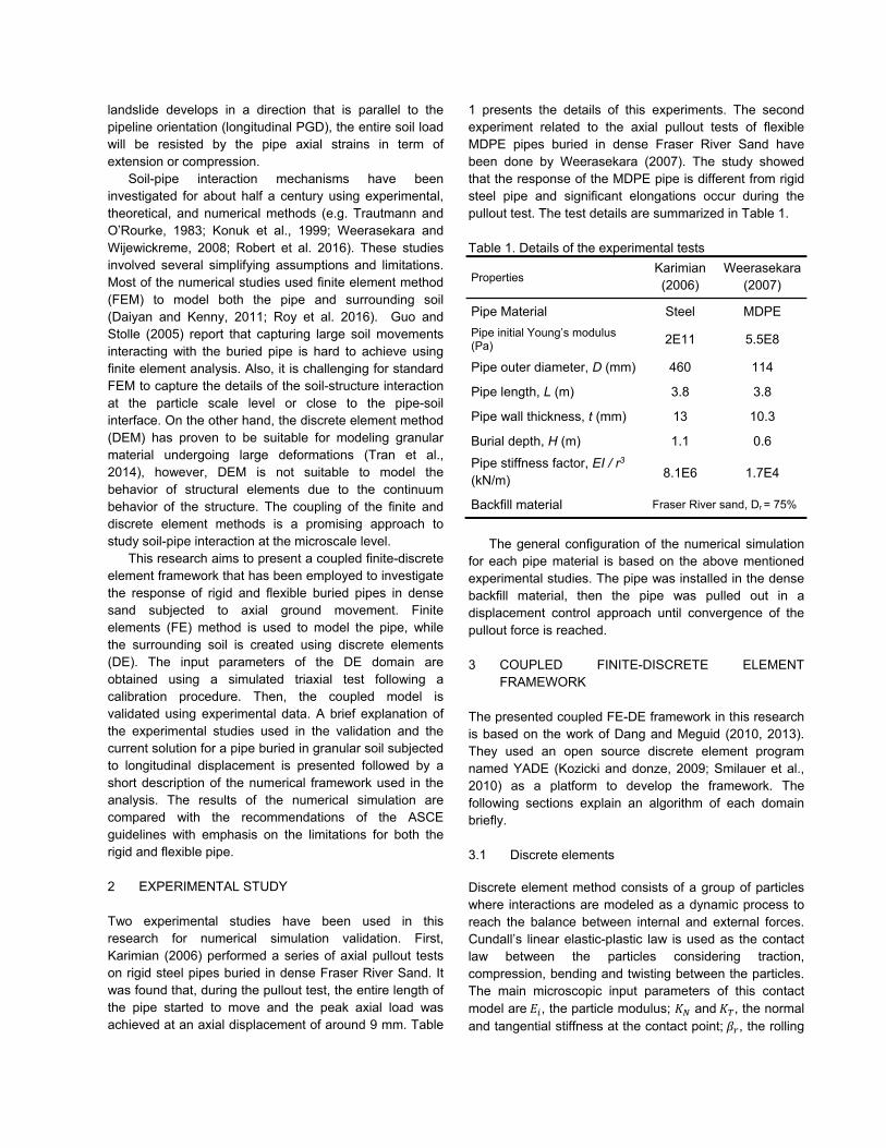
Figure 1. Coupling FE and DE using interface elements
3.3 Interface elements
The interface elements are introduced to transfer the contact forces between FE and DE domains. These elements are generated directly from FE nodes by dividing the contact surface between the FE and DE into four triangles by adding a temporary node defined below:
𝑋 14 𝑋 4
where 𝑋 is the coordinate of node i of the quadrilateral. Fig. 1 shows a schematic view of the spherical particles in interact with a finite elements with the interface elements on the contact surfaces. The same contact law of DE domain is used between the interface elements and discrete particles. A detailed typical FE-DE computational cycle and its main steps are described in y Dang and Meguid (2010, 2013).
4 SOIL-PIPE INTERACTION
The general solution for the soil load on a pipe subjected to axial soil movement can be approximated by the bilinear relationship as depicted in Fig. 2a (Rajani et al. 1995).The initial response is linear until reaching the ultimate relative soil displacement (Du). The ultimate soil resistance (Pu) is developed when the relative soil displacement exceeds its limit (Du). The maximum axial soil force per unit length of the pipe in the granular soil can be calculated using a simple formula which is recommended by multiple guidelines (ASCE, 1984; ALA, 2001; PRCI, 2004)
𝑃 𝛾 𝐻 𝜋 𝐷 1 𝑘2 𝑡𝑎𝑛 𝛿 5
where 𝑃 is the ultimate soil load, 𝛾 is unit weight of soil, 𝐻 is the pipe burial depth, 𝐷 is pipe diameter, 𝑘 is the lateral earth pressure coefficient at rest and 𝛿 is the interface friction angle between the pipe and soil. This equation is developed by calculating an average effective normal stress acting along the interface between the pipe and soil (Fig. 2b). The assumptions in this equation are as follows:
1- The soil around the pipe remains at rest even after shear displacements occur at the soil-pipe interface.
2- The distribution of normal stresses on the pipe assumes that the pipe is rigid.
3- The axial soil resistance per-unit length of the pipe is constant along its length.
Considering the above assumptions, it can be concluded that the recommended equation in current guidelines is primarily applicable to rigid steel pipes and that the response of flexible pipes in dense soils requires further investigations.
DE DE
DE
FE
Defined center node
Triangular Interface elements
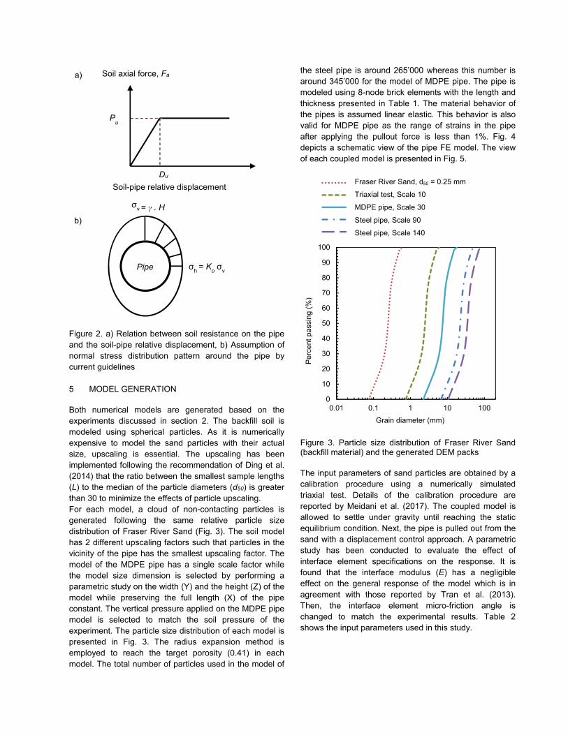
Figure 2. a) Relation between soil resistance on the pipe and the soil-pipe relative displacement, b) Assumption of normal stress distribution pattern around the pipe by current guidelines
5 MODEL GENERATION
Both numerical models are generated based on the experiments discussed in section 2. The backfill soil is modeled using spherical particles. As it is numerically expensive to model the sand particles with their actual size, upscaling is essential. The upscaling has been implemented following the recommendation of Ding et al. (2014) that the ratio between the smallest sample lengths (L) to the median of the particle diameters (d50) is greater than 30 to minimize the effects of particle upscaling. For each model, a cloud of non-contacting particles is generated following the same relative particle size distribution of Fraser River Sand (Fig. 3). The soil model has 2 different upscaling factors such that particles in the vicinity of the pipe has the smallest upscaling factor. The model of the MDPE pipe has a single scale factor while the model size dimension is selected by performing a parametric study on the width (Y) and the height (Z) of the model while preserving the full length (X) of the pipe constant. The vertical pressure applied on the MDPE pipe model is selected to match the soil pressure of the experiment. The particle size distribution of each model is presented in Fig. 3. The radius expansion method is employed to reach the target porosity (0.41) in each model. The total number of particles used in the model of
the steel pipe is around 265’000 whereas this number is around 345’000 for the model of MDPE pipe. The pipe is modeled using 8-node brick elements with the length and thickness presented in Table 1. The material behavior of the pipes is assumed linear elastic. This behavior is also valid for MDPE pipe as the range of strains in the pipe after applying the pullout force is less than 1%. Fig. 4 depicts a schematic view of the pipe FE model. The view of each coupled model is presented in Fig. 5.
Figure 3. Particle size distribution of Fraser River Sand (backfill material) and the generated DEM packs
The input parameters of sand particles are obtained by a calibration procedure using a numerically simulated triaxial test. Details of the calibration procedure are reported by Meidani et al. (2017). The coupled model is allowed to settle under gravity until reaching the static equilibrium condition. Next, the pipe is pulled out from the sand with a displacement control approach. A parametric study has been conducted to evaluate the effect of interface element specifications on the response. It is found that the interface modulus (E) has a negligible effect on the general response of the model which is in agreement with those reported by Tran et al. (2013). Then, the interface element micro-friction angle is changed to match the experimental results. Table 2 shows the input parameters used in this study.
0
10
20
30
40
50
60
70
80
90
100
0.01 0.1 1 10 100
Perc
ent p
assi
ng (%
)
Grain diameter (mm)
Fraser river sandTriaxial Test-Scale 10MDPE pipe-Scale 30Steel pipe-Scale 90Steel pipe-Scale 140
Soil axial force, Fa
Soil-pipe relative displacement Du
Pu
Pipe
σv = γ . H
σh = Ko σv
Fraser River Sand, d50 = 0.25 mm
Triaxial test, Scale 10
MDPE pipe, Scale 30
Steel pipe, Scale 90
Steel pipe, Scale 140 b)
a)
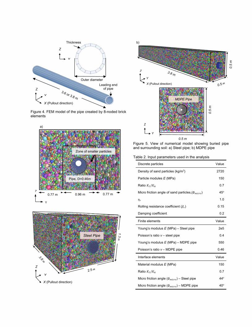
Figure 4. FEM model of the pipe created by 8-noded brick elements
Figure 5. View of numerical model showing buried pipe and surrounding soil: a) Steel pipe; b) MDPE pipe
Table 2. Input parameters used in the analysis
Discrete particles Value
Density of sand particles (kg/m3) 2720
Particle modules E (MPa) 150
Ratio 𝐾 /𝐾 0.7
Micro friction angle of sand particles,(∅ ) 45o 𝜂 1.0
Rolling resistance coefficient (𝛽 ) 0.15
Damping coefficient 0.2
Finite elements Value
Young’s modulus E (MPa) – Steel pipe 2e5
Poisson’s ratio ν – steel pipe 0.4
Young’s modulus E (MPa) – MDPE pipe 550
Poisson’s ratio ν – MDPE pipe 0.46
Interface elements Value
Material modulus E (MPa) 150
Ratio 𝐾 /𝐾 0.7
Micro friction angle (∅ ) – Steel pipe 44o
Micro friction angle (∅ ) – MDPE pipe 40o
Thickness
Outer diameterLeading end
of pipe
Y
Z
X (Pullout direction)
Y
Z
Pipe, D=0.46m
Zone of smaller particles
Z0.96 m 0.77 m
Y
0.77 m
a)
Y
Z
X (Pullout direction)
Steel Pipe
Y
Z
X (Pullout direction)
0.5
m
Y
Z
b)
0.5 m
0.5
m
MDPE Pipe
6 RESULTS AND DISCUSSION
6.1 Steel pipe
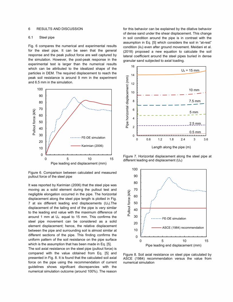
Fig. 6 compares the numerical and experimental results for the steel pipe. It can be seen that the general response and the peak pullout force are well captured by the simulation. However, the post-peak response in the experimental test is larger than the numerical results which can be attributed to the idealized shape of the particles in DEM. The required displacement to reach the peak soil resistance is around 9 mm in the experiment and 6.5 mm in the simulation.
Figure 6. Comparison between calculated and measured pullout force of the steel pipe
It was reported by Karimian (2006) that the steel pipe was moving as a solid element during the pullout test and negligible elongation occurred in the pipe. The horizontal displacement along the steel pipe length is plotted in Fig. 7 at six different leading end displacements (Ux).The displacement of the tailing end of the pipe is very similar to the leading end value with the maximum difference of around 1 mm at Ux equal to 15 mm. This confirms the steel pipe movement can be considered as a solid element displacement; hence, the relative displacement between the pipe and surrounding soil is almost similar at different sections of the pipe. This finding confirms the uniform pattern of the soil resistance on the pipe surface which is the assumption that has been made in Eq. [5]. The soil axial resistance on the steel pipe (pullout force) is compared with the value obtained from Eq. [5] and presented in Fig. 8. It is found that the calculated soil axial force on the pipe using the recommendation of current guidelines shows significant discrepancies with the numerical simulation outcome (around 100%). The reason
for this behavior can be explained by the dilative behavior of dense sand under the shear displacement. This change in soil condition around the pipe is in contrast with the assumption in Eq. [5] which considers the soil in “at-rest” condition (k0) even after ground movement. Meidani et al. (2018) proposed a new equation to calculate the soil lateral coefficient around the steel pipes buried in dense granular sand subjected to axial loading.
Figure 7. Horizontal displacement along the steel pipe at different leading end displacement (Ux)
Figure 8. Soil axial resistance on steel pipe calculated by ASCE (1984) recommendation versus the value from numerical simulation
0
10
20
30
40
50
60
70
80
90
100
0 5 10 15
Pullo
ut fo
rce
(kN
)
Pipe leading end displacement (mm)
FE-DE simulation
Karimian (2006)
0
2
4
6
8
10
12
14
16
0 0.6 1.2 1.8 2.4 3 3.6
Pipe
hor
izon
tal d
ispl
acem
ent (
mm
)
Length along the pipe (m)
0
10
20
30
40
50
60
70
80
90
100
0 5 10 15
Pullo
ut fo
rce
(kN
)
Pipe leading end displacement (mm)
FE-DE simulation
ASCE (1984) recommendation
Ux = 15 mm
10 mm
5 mm
2.5 mm
0.5 mm
7.5 mm
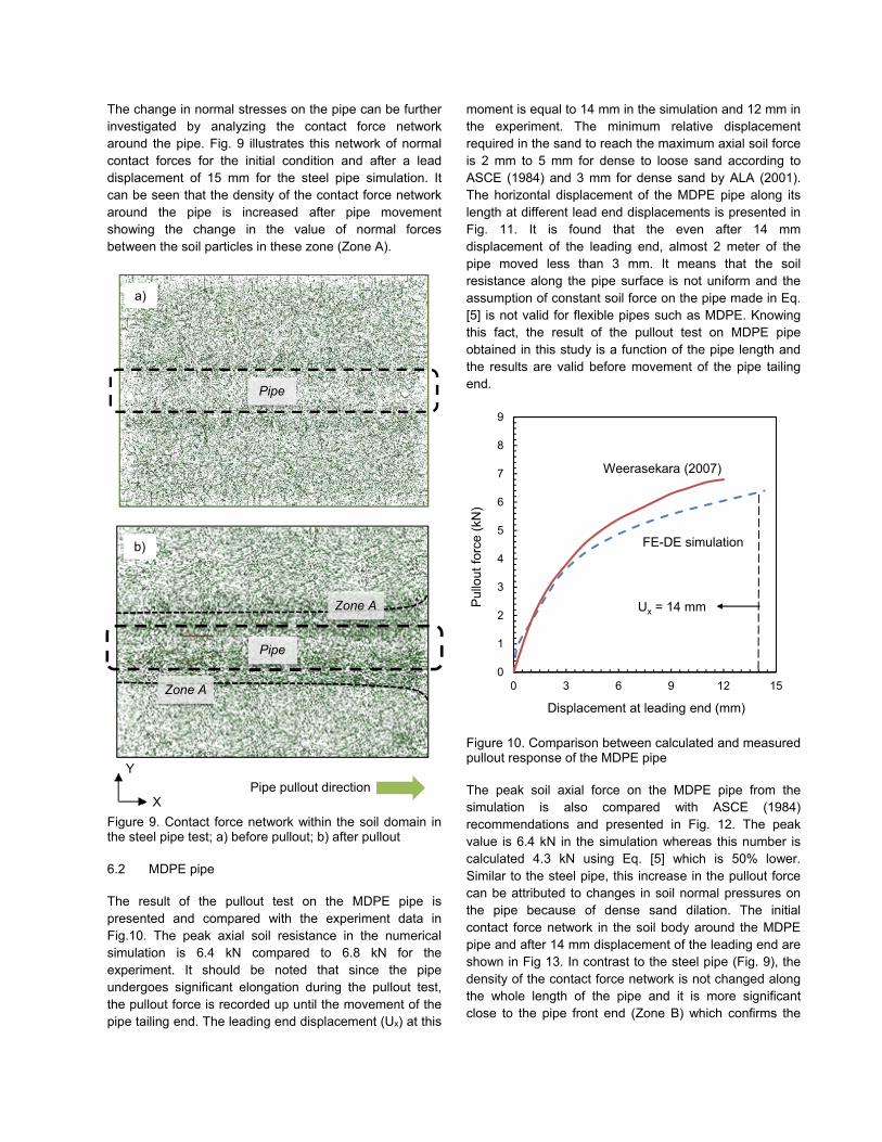
The change in normal stresses on the pipe can be further investigated by analyzing the contact force network around the pipe. Fig. 9 illustrates this network of normal contact forces for the initial condition and after a lead displacement of 15 mm for the steel pipe simulation. It can be seen that the density of the contact force network around the pipe is increased after pipe movement showing the change in the value of normal forces between the soil particles in these zone (Zone A).
Figure 9. Contact force network within the soil domain in the steel pipe test; a) before pullout; b) after pullout
6.2 MDPE pipe
The result of the pullout test on the MDPE pipe is presented and compared with the experiment data in Fig.10. The peak axial soil resistance in the numerical simulation is 6.4 kN compared to 6.8 kN for the experiment. It should be noted that since the pipe undergoes significant elongation during the pullout test, the pullout force is recorded up until the movement of the pipe tailing end. The leading end displacement (Ux) at this
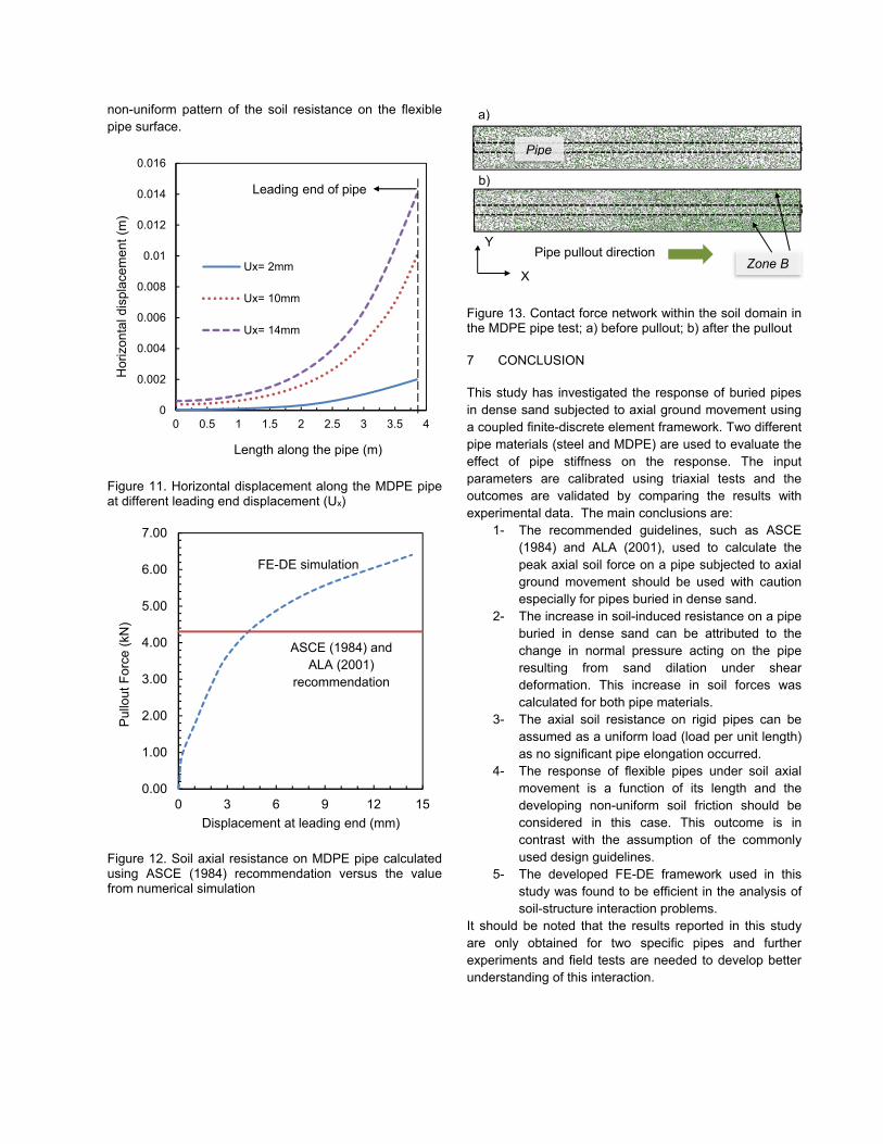
moment is equal to 14 mm in the simulation and 12 mm in the experiment. The minimum relative displacement required in the sand to reach the maximum axial soil force is 2 mm to 5 mm for dense to loose sand according to ASCE (1984) and 3 mm for dense sand by ALA (2001). The horizontal displacement of the MDPE pipe along its length at different lead end displacements is presented in Fig. 11. It is found that the even after 14 mm displacement of the leading end, almost 2 meter of the pipe moved less than 3 mm. It means that the soil resistance along the pipe surface is not uniform and the assumption of constant soil force on the pipe made in Eq. [5] is not valid for flexible pipes such as MDPE. Knowing this fact, the result of the pullout test on MDPE pipe obtained in this study is a function of the pipe length and the results are valid before movement of the pipe tailing end.
Figure 10. Comparison between calculated and measured pullout response of the MDPE pipe
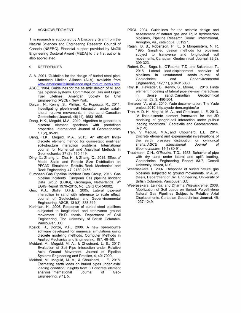
The peak soil axial force on the MDPE pipe from the simulation is also compared with ASCE (1984) recommendations and presented in Fig. 12. The peak value is 6.4 kN in the simulation whereas this number is calculated 4.3 kN using Eq. [5] which is 50% lower. Similar to the steel pipe, this increase in the pullout force can be attributed to changes in soil normal pressures on the pipe because of dense sand dilation. The initial contact force network in the soil body around the MDPE pipe and after 14 mm displacement of the leading end are shown in Fig 13. In contrast to the steel pipe (Fig. 9), the density of the contact force network is not changed along the whole length of the pipe and it is more significant close to the pipe front end (Zone B) which confirms the
0
1
2
3
4
5
6
7
8
9
0 3 6 9 12 15
Pullo
ut fo
rce
(kN
)
Displacement at leading end (mm)
FE-DE simulation
Weerasekara (2007)
Ux = 14 mm
a)
Pipe
Pipe pullout direction Y
X
Pipe
Zone A
b)
Zone A
non-uniform pattern of the soil resistance on the flexible pipe surface.
Figure 11. Horizontal displacement along the MDPE pipe at different leading end displacement (Ux)
Figure 12. Soil axial resistance on MDPE pipe calculated using ASCE (1984) recommendation versus the value from numerical simulation
Figure 13. Contact force network within the soil domain in the MDPE pipe test; a) before pullout; b) after the pullout
7 CONCLUSION
This study has investigated the response of buried pipes in dense sand subjected to axial ground movement using a coupled finite-discrete element framework. Two different pipe materials (steel and MDPE) are used to evaluate the effect of pipe stiffness on the response. The input parameters are calibrated using triaxial tests and the outcomes are validated by comparing the results with experimental data. The main conclusions are:
1- The recommended guidelines, such as ASCE (1984) and ALA (2001), used to calculate the peak axial soil force on a pipe subjected to axial ground movement should be used with caution especially for pipes buried in dense sand.
2- The increase in soil-induced resistance on a pipe buried in dense sand can be attributed to the change in normal pressure acting on the pipe resulting from sand dilation under shear deformation. This increase in soil forces was calculated for both pipe materials.
3- The axial soil resistance on rigid pipes can be assumed as a uniform load (load per unit length) as no significant pipe elongation occurred.
4- The response of flexible pipes under soil axial movement is a function of its length and the developing non-uniform soil friction should be considered in this case. This outcome is in contrast with the assumption of the commonly used design guidelines.
5- The developed FE-DE framework used in this study was found to be efficient in the analysis of soil-structure interaction problems.
It should be noted that the results reported in this study are only obtained for two specific pipes and further experiments and field tests are needed to develop better understanding of this interaction.
0
0.002
0.004
0.006
0.008
0.01
0.012
0.014
0.016
0 0.5 1 1.5 2 2.5 3 3.5 4
Hor
izon
tal d
ispl
acem
ent (
m)
Length along the pipe (m)
Ux= 2mm
Ux= 10mm
Ux= 14mm
Leading end of pipe
0.00
1.00
2.00
3.00
4.00
5.00
6.00
7.00
0 3 6 9 12 15
Pullo
ut F
orce
(kN
)
Displacement at leading end (mm)
X
a)
b)
YPipe pullout direction
Pipe
Zone B
FE-DE simulation
ASCE (1984) and ALA (2001)
recommendation
8 ACKNOWLEDGMENT
This research is supported by A Discovery Grant from the Natural Sciences and Engineering Research Council of Canada (NSERC). Financial support provided by McGill Engineering Doctoral Award (MEDA) to the first author is also appreciated. 9 REFERENCES
ALA. 2001. Guideline for the design of buried steel pipe. American Lifeline Alliance (ALA), available from www.americanlifelinealliance.org/Product_new3.htm
ASCE. 1984. Guidelines for the seismic design of oil and gas pipeline systems. Committee on Gas and Liquid Fuel Lifelines, American Society for Civil Engineering (ASCE), New York.
Daiyan, N., Kenny, S., Phillips, R., Popescu, R., 2011. Investigating pipeline-soil interaction under axial–lateral relative movements in the sand. Canadian Geotechnical Journal, 48(11), 1683-1695.
Dang, H.K., Meguid, M.A., 2010. Algorithm to generate a discrete element specimen with predefined properties. International Journal of Geomechanics 10 (2), 85-91.
Dang, H.K., Meguid, M.A., 2013. An efficient finite-discrete element method for quasi-static nonlinear soil-structure interaction problems. International Journal for Numerical and Analytical Methods in Geomechanics 37 (2), 130-149.
Ding, X., Zhang, L., Zhu, H., & Zhang, Q., 2014. Effect of Model Scale and Particle Size Distribution on PFC3D Simulation Results. Rock Mechanics and Rock Engineering. 47, 2139-2156.
European Gas Pipeline Incident Data Group, 2015. Gas pipeline incidents. European Gas pipeline Incident Data Group (EGIG), Groningen, Netherlands. 9th EGIG Report 1970–2015, No. EGIG 05-R-0002.
Guo, P.J., Stolle, D.F.E., 2005. Lateral pipe-soil interaction in sand with reference to scale effect, Journal of Geotechnical and Geoenvironmental Engineering, ASCE, 131(3), 338-349.
Karimian, H., 2006. Response of buried steel pipelines subjected to longitudinal and transverse ground movement. Ph.D. thesis, Department of Civil Engineering, The University of British Columbia, Vancouver, B.C.
Kozicki, J., Donzé, V.F., 2008. A new open-source software developed for numerical simulations using discrete modeling methods, Computer Methods in Applied Mechanics and Engineering, 197, 49–50.
Meidani, M., Meguid, M. A., & Chouinard, L. E., 2017. Evaluation of Soil–Pipe Interaction under Relative Axial Ground Movement. Journal of Pipeline Systems Engineering and Practice, 4, 4017009.
Meidani, M., Meguid, M. A., & Chouinard, L. E. 2018. Estimating earth loads on buried pipes under axial loading condition: insights from 3D discrete element analysis. International Journal of Geo-Engineering, 9(1), 5.
PRCI. 2004, Guidelines for the seismic design and assessment of natural gas and liquid hydrocarbon pipelines, Pipeline Research Council International, Arlington, Va., catalogue. L51927.
Rajani, B. B., Robertson, P. K., & Morgenstern, N. R. 1995. Simplified design methods for pipelines subject to transverse and longitudinal soil movements. Canadian Geotechnical Journal, 32(2), 309-323.
Robert, D.J., Soga, K., O’Rourke, T.D. and Sakanoue, T., 2016. Lateral load-displacement behavior of pipelines in unsaturated sands. Journal of Geotechnical and Geoenvironmental Engineering, 142(11), p.04016060.
Roy, K., Hawlader, B., Kenny, S., Moore, I., 2016. Finite element modeling of lateral pipeline–soil interactions in dense sand. Canadian Geotechnical Journal, 53, 3, 490-504.
Smilauer, V., et al., 2010. Yade documentation. The Yade project 2010, http://yade-dem.org/doc/æ
Tran, V. D. H., Meguid, M. A., and Chouinard, L. E. 2013. “A finite-discrete element framework for the 3D modeling of geogrid-soil interaction under pullout loading conditions.” Geotextile and Geomembrane. 37(1-9).
Tran, V., Meguid, M.A., and Chouinard, L.E. 2014. Discrete element and experimental investigations of the earth pressure distribution on cylindrical shafts. ASCE International Journal of Geomechanics, 14(1) 80-91.
Trautmann, C.H., O’Rourke, T.D., 1983. Behavior of pipe with dry sand under lateral and uplift loading, Geotechnical Engineering Report 83-7, Cornell University, Ithaca, N.Y.
Weerasekara, L. 2007. Response of buried natural gas pipelines subjected to ground movements. M.A.Sc. thesis, Department of Civil Engineering, University of British Columbia, Vancouver, B.C.
Weerasekara, Lalinda, and Dharma Wijewickreme. 2008. Mobilization of Soil Loads on Buried, Polyethylene Natural Gas Pipelines Subject to Relative Axial Displacements. Canadian Geotechnical Journal. 45: 1237-1249.