Embed Size (px)
Citation preview
1© 2006 Bernd Bruegge Software Engineering WS 2006/2007
Modeling with UML:Basic Notations
Prof. Bernd Bruegge, Ph.D.Applied Software Engineering
Technische Universitaet Muenchen
Software Engineering ILecture 2
7 November 2006
2© 2006 Bernd Bruegge Software Engineering WS 2006/2007
Overview
• Odds and Ends• Modeling• The UML notation• Use case diagrams• Class diagrams• Sequence diagrams• Activity diagrams
3© 2006 Bernd Bruegge Software Engineering WS 2006/2007
Odds and Ends (1)
• Reading for this Week:• Chapter 1 and 2, Bruegge&Dutoit, Object-OrientedSoftware Engineering
• Software Engineering I Portal• http://wwwbruegge.in.tum.de/static/contribute/Lehrst
uhl/SoftwareTechnikWiSe05.htm
• Lectures Slides:• Will be sent to you via e-mail if you are registered for this class.

4© 2006 Bernd Bruegge Software Engineering WS 2006/2007
Lecture Schedule
• Oct 31: Modeling with UML moved to Nov 7
• Nov 7: Project Organization moved to January
• Nov 14: Functional Modeling• Nov 21: Dynamic Modeling• Nov 28: Architectural Styles• Nov 30: Reuse• Dec 5: No lecture• Dec 12: Design Patterns• Dec 19: Object Constraint
Language
• Nov 1: Holiday (Allerheiligen)
• Nov 8: RequirementsElicitation
• Nov 15: Object Modeling• Nov 22: Design Goals• Nov 29: Addressing Design
Goals
• Dec 6: No lecture• Dec 13: Interface Specification• Dec 20: Mid-term
Tuesdays 12:15-13:45 Oct 24: Introduction
Wednesday 9:15-10:00• Oct 25: Introduction ctd
Always subject to Change!
5© 2006 Bernd Bruegge Software Engineering WS 2006/2007
What is modeling?
• Modeling consists of building an abstraction ofreality
• Abstractions are simplifications because:• They ignore irrelevant details and• They only represent the relevant details
• What is relevant or irrelevant depends on thepurpose of the model.
• Models can be used for 2 purposes:• Gain insight into the past and presence• Predict future behavior.
6© 2006 Bernd Bruegge Software Engineering WS 2006/2007
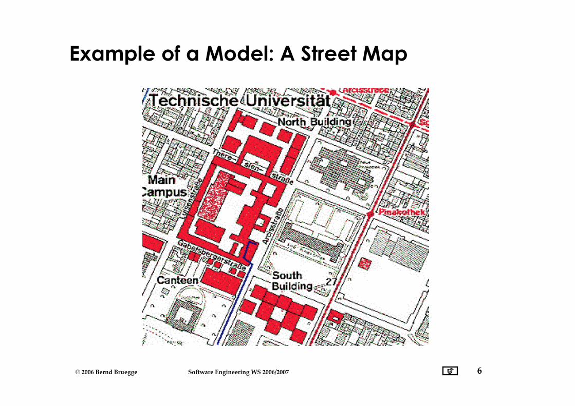
Example of a Model: A Street Map
7© 2006 Bernd Bruegge Software Engineering WS 2006/2007
Why should we model Software?
• Software is used in many appliances andeveryday objects
• Software is getting increasingly more complex• Windows 2000: ~ 40 millions lines of code• A single programmer cannot manage this amount of
code in its entirety
• Code is not easily understandable by developerswho did not write it
• We need simpler representations for complexsystems• Modeling is a mean for dealing with complexity.
8© 2006 Bernd Bruegge Software Engineering WS 2006/2007
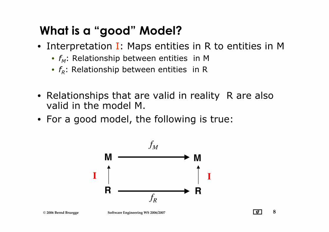
What is a “good” Model?• Interpretation I: Maps entities in R to entities in M
• fM: Relationship between entities in M• fR: Relationship between entities in R
• Relationships that are valid in reality R are alsovalid in the model M.
• For a good model, the following is true:
fM
fR
MM
R RI I
9© 2006 Bernd Bruegge Software Engineering WS 2006/2007
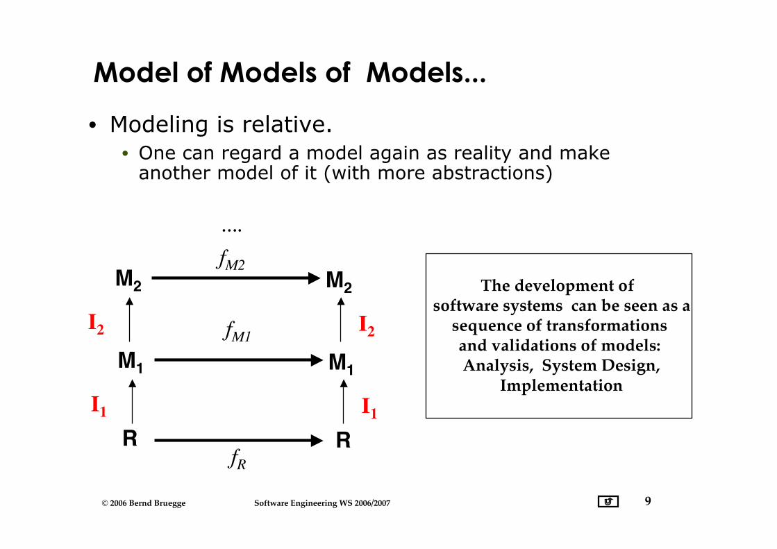
Model of Models of Models...
• Modeling is relative.• One can regard a model again as reality and make
another model of it (with more abstractions)
fM1
fR
M1M1
R RI1 I1
M2M2
I2 I2
fM2
….
The development of software systems can be seen as a
sequence of transformations and validations of models: Analysis, System Design,
Implementation
10© 2006 Bernd Bruegge Software Engineering WS 2006/2007
fM1
fR
M1M1
R RI1
M2M2
I2
fM2
….
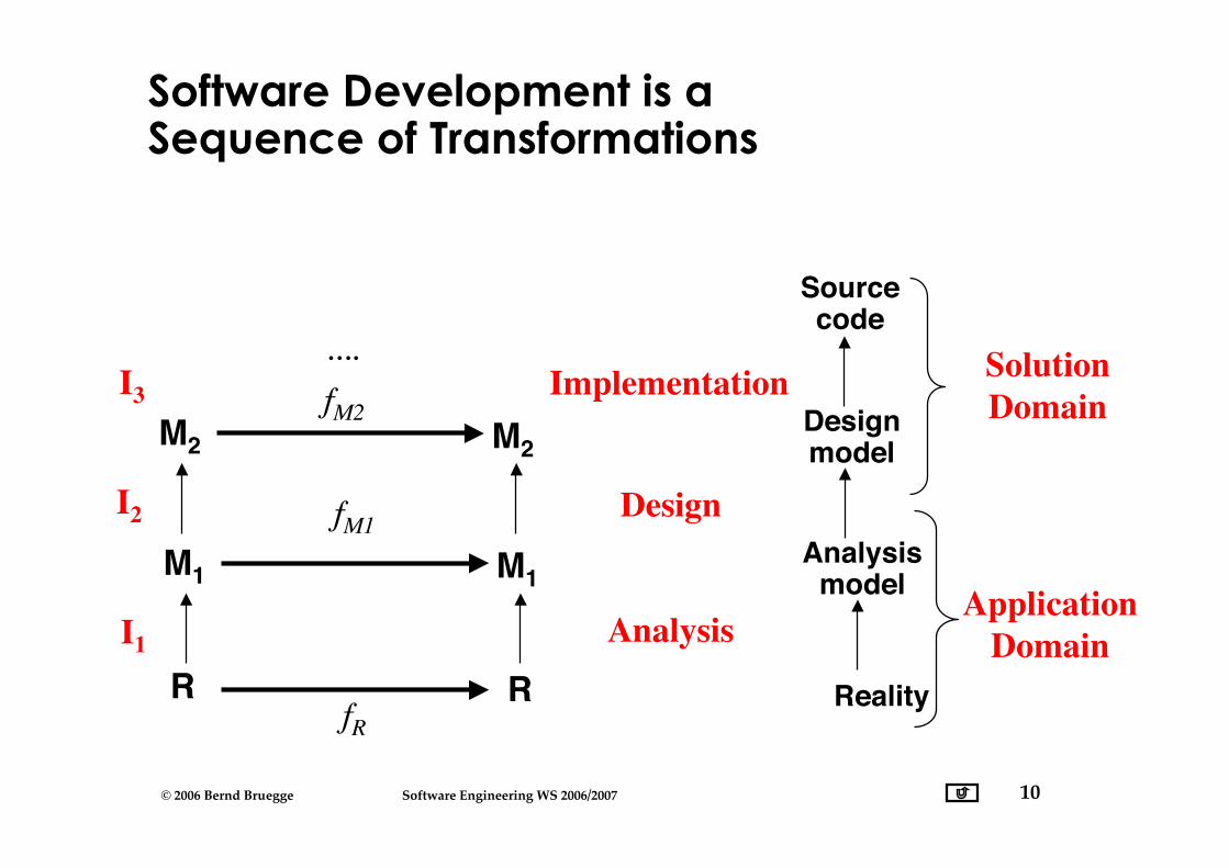
Software Development is aSequence of Transformations
Reality
Analysismodel
Analysis
Designmodel
Design
Sourcecode
Implementation SolutionDomain
ApplicationDomain
I3
11© 2006 Bernd Bruegge Software Engineering WS 2006/2007
Models must be falsifiable
• Karl Popper (“Objective Knowledge):• There is no absolute truth when trying to understand reality• One can only build theories, that are “true” until somebody
finds a counter example
• Falsification: The act of disproving a theory or hypothesis• The truth of a theory is never certain. We must use
phrases like:• “by our best judgement”, “using state-of-the-art knowledge”
• In software engineering any model is a theory:• We build models and try to find counter examples by:
• Requirements validation, user interface testing, review ofthe design, source code testing, system testing, etc.
• Testing: The act of disproving a model.
12© 2006 Bernd Bruegge Software Engineering WS 2006/2007
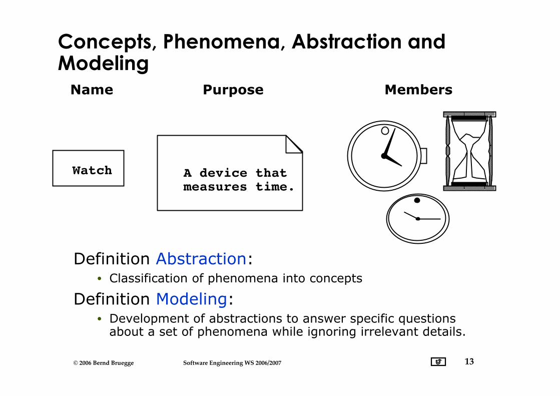
Concepts and Phenomena
• Phenomenon• An object in the world of a domain as you perceive it
• Examples: This lecture on November 7 at 12:30, myblack watch
• Concept• Describes the common properties of phenomena
• Example: All lectures on software engineering• Example: All black watches
• A Concept is a 3-tuple:• Name: The name distinguishes the concept from other
concepts• Purpose: Properties that determine if a phenomenon is
a member of a concept• Members: The set of phenomena which are part of the
concept.
13© 2006 Bernd Bruegge Software Engineering WS 2006/2007
Definition Abstraction:• Classification of phenomena into concepts
Definition Modeling:• Development of abstractions to answer specific questions
about a set of phenomena while ignoring irrelevant details.
MembersName
Watch
Purpose
A device thatmeasures time.
Concepts, Phenomena, Abstraction andModeling
14© 2006 Bernd Bruegge Software Engineering WS 2006/2007
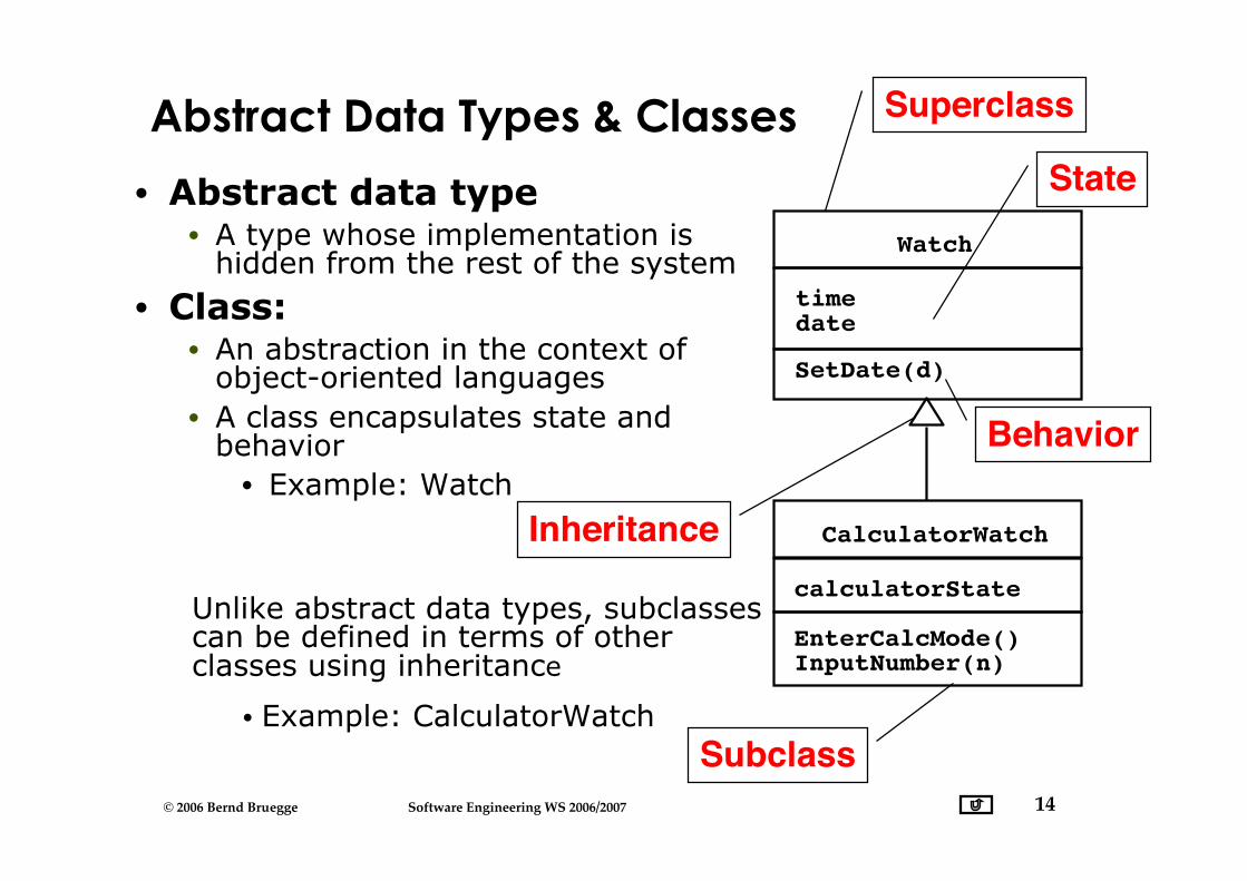
Abstract Data Types & Classes
• Abstract data type• A type whose implementation is
hidden from the rest of the system
• Class:• An abstraction in the context of
object-oriented languages• A class encapsulates state and
behavior• Example: Watch
Watch
timedate
SetDate(d)
CalculatorWatch
EnterCalcMode()InputNumber(n)
calculatorStateUnlike abstract data types, subclassescan be defined in terms of otherclasses using inheritance
State
Behavior
Inheritance
Subclass• Example: CalculatorWatch
Superclass
15© 2006 Bernd Bruegge Software Engineering WS 2006/2007
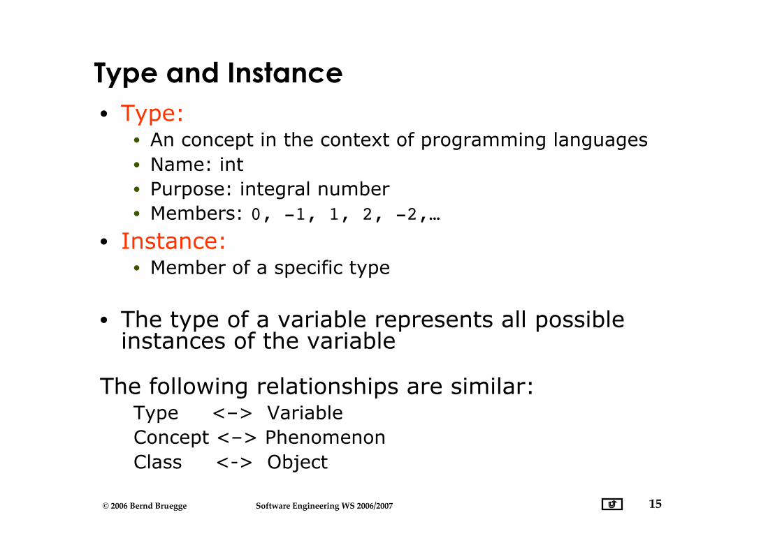
Type and Instance• Type:
• An concept in the context of programming languages• Name: int• Purpose: integral number• Members: 0, -1, 1, 2, -2,…
• Instance:• Member of a specific type
• The type of a variable represents all possibleinstances of the variable
The following relationships are similar:Type <–> VariableConcept <–> PhenomenonClass <-> Object
16© 2006 Bernd Bruegge Software Engineering WS 2006/2007
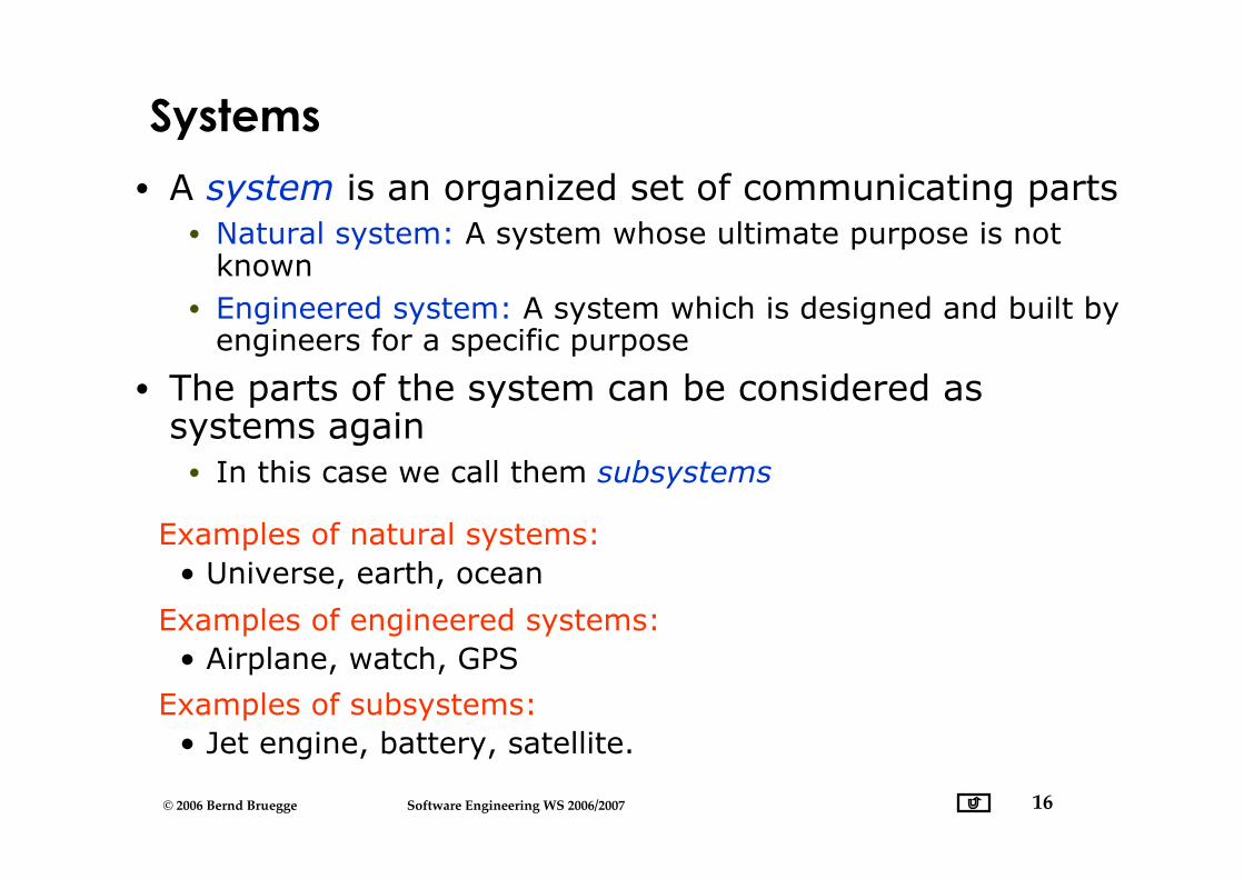
Systems
• A system is an organized set of communicating parts• Natural system: A system whose ultimate purpose is not
known• Engineered system: A system which is designed and built by
engineers for a specific purpose
• The parts of the system can be considered assystems again• In this case we call them subsystems
Examples of engineered systems: • Airplane, watch, GPS
Examples of subsystems: • Jet engine, battery, satellite.
Examples of natural systems: • Universe, earth, ocean
17© 2006 Bernd Bruegge Software Engineering WS 2006/2007
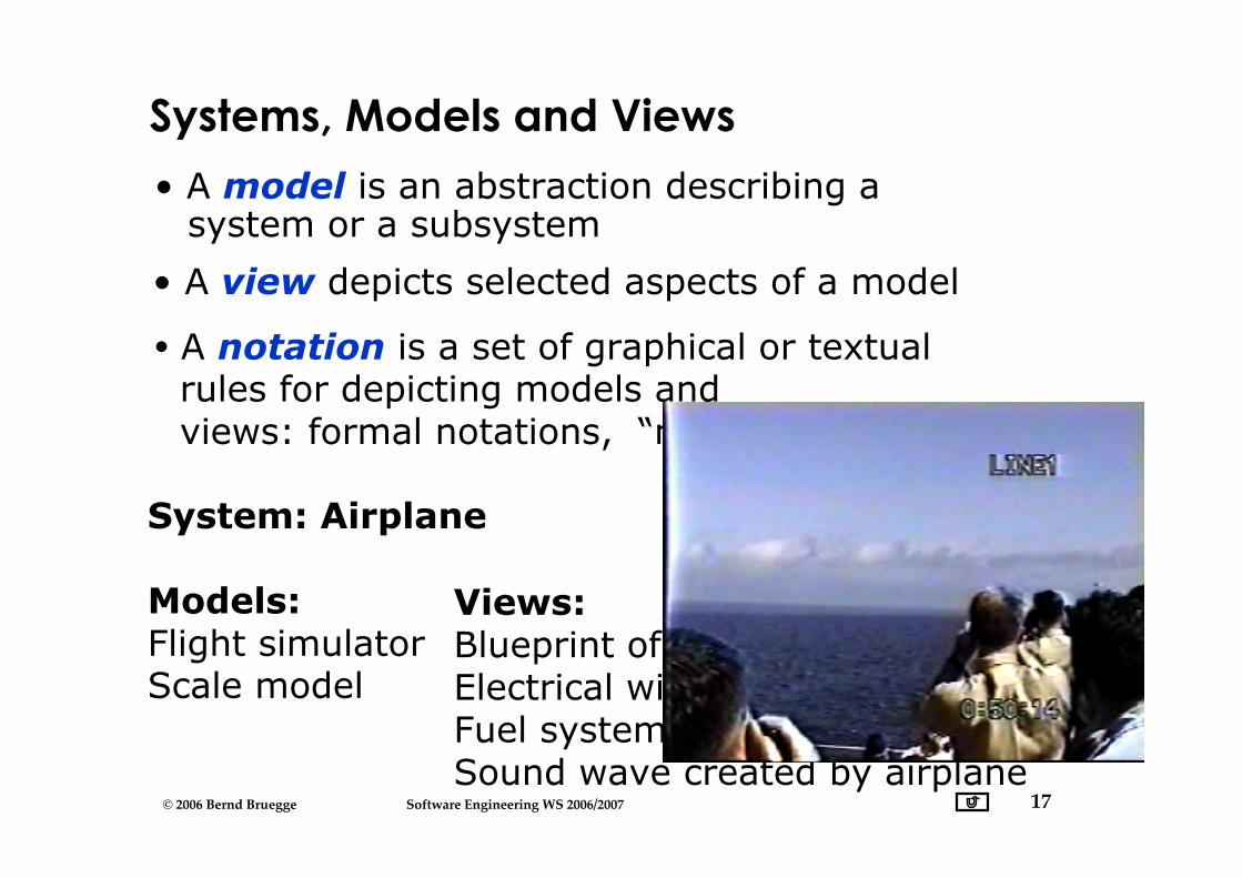
Systems, Models and Views
• A model is an abstraction describing asystem or a subsystem
System: Airplane
Models:Flight simulatorScale model
Views:Blueprint of the airplane componentsElectrical wiring diagramFuel systemSound wave created by airplane
• A view depicts selected aspects of a model
• A notation is a set of graphical or textual rules for depicting models and views: formal notations, “napkin notations”
18© 2006 Bernd Bruegge Software Engineering WS 2006/2007
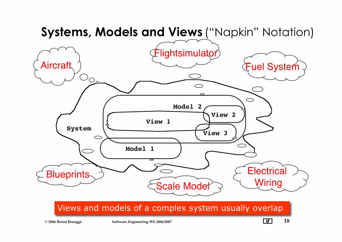
SystemView 1
Model 2
View 2
View 3
Model 1
Aircraft Flightsimulator
Scale ModelBlueprints Electrical
Wiring
Fuel System
Views and models of a complex system usually overlap
(“Napkin” Notation)Systems, Models and Views
19© 2006 Bernd Bruegge Software Engineering WS 2006/2007
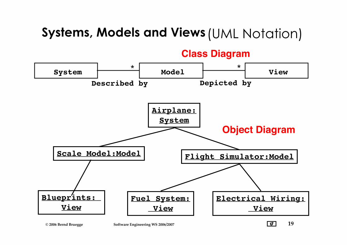
Systems, Models and Views
System View*
Model*
Depicted byDescribed by
Airplane:System
Scale Model:Model Flight Simulator:Model
Fuel System: View
Electrical Wiring: View
Blueprints: View
(UML Notation)Class Diagram
Object Diagram
20© 2006 Bernd Bruegge Software Engineering WS 2006/2007
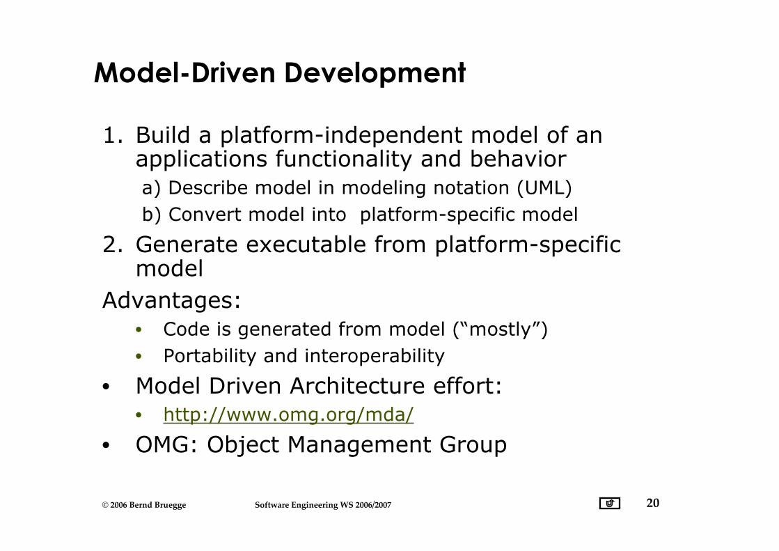
Model-Driven Development
1. Build a platform-independent model of anapplications functionality and behavior a) Describe model in modeling notation (UML) b) Convert model into platform-specific model
2. Generate executable from platform-specificmodel
Advantages:• Code is generated from model (“mostly”)• Portability and interoperability
• Model Driven Architecture effort:• http://www.omg.org/mda/
• OMG: Object Management Group
21© 2006 Bernd Bruegge Software Engineering WS 2006/2007
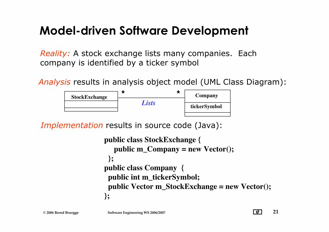
Reality: A stock exchange lists many companies. Eachcompany is identified by a ticker symbol
Analysis results in analysis object model (UML Class Diagram):
StockExchange Company
tickerSymbolLists **
Implementation results in source code (Java):
public class StockExchange { public m_Company = new Vector(); };public class Company { public int m_tickerSymbol; public Vector m_StockExchange = new Vector();};
Model-driven Software Development
22© 2006 Bernd Bruegge Software Engineering WS 2006/2007
Application vs Solution Domain
• Application Domain (Analysis):• The environment in which the system is operating
• Solution Domain (Design, Implementation):• The technologies used to build the system
• Both domains contain abstractions that we canuse for the construction of the system model.

23© 2006 Bernd Bruegge Software Engineering WS 2006/2007
Object-oriented Modeling
Application Domain (Phenomena)
Solution Domain (Phenomena)
System Model (Concepts) System Model (Concepts)
Aircraft TrafficController
FlightPlanAirport
MapDisplay
FlightPlanDatabase
SummaryDisplay
TrafficControl
TrafficControl
UML Package
(Analysis) (Design)
24© 2006 Bernd Bruegge Software Engineering WS 2006/2007
What is UML?
• UML (Unified Modeling Language)• Nonproprietary standard for modeling software systems, OMG• Convergence of notations used in object-oriented methods
• OMT (James Rumbaugh and collegues)• Booch (Grady Booch)• OOSE (Ivar Jacobson)
• Current Version 2.0• Information at the OMG portal http://www.uml.org/
• Commercial tools: Rational (IBM),Together (Borland), VisualArchitect (business processes, BCD)
• Open Source tools: ArgoUML, StarUML, Umbrello
• Commercial and Opensource: PoseidonUML (Gentleware)
25© 2006 Bernd Bruegge Software Engineering WS 2006/2007
UML: First Pass
• You can model 80% of most problems by usingabout 20 % UML
• We teach you those 20%
• 80-20 rule: Pareto principle• http://www.ephorie.de/hindle_pareto-prinzip.htm
26© 2006 Bernd Bruegge Software Engineering WS 2006/2007
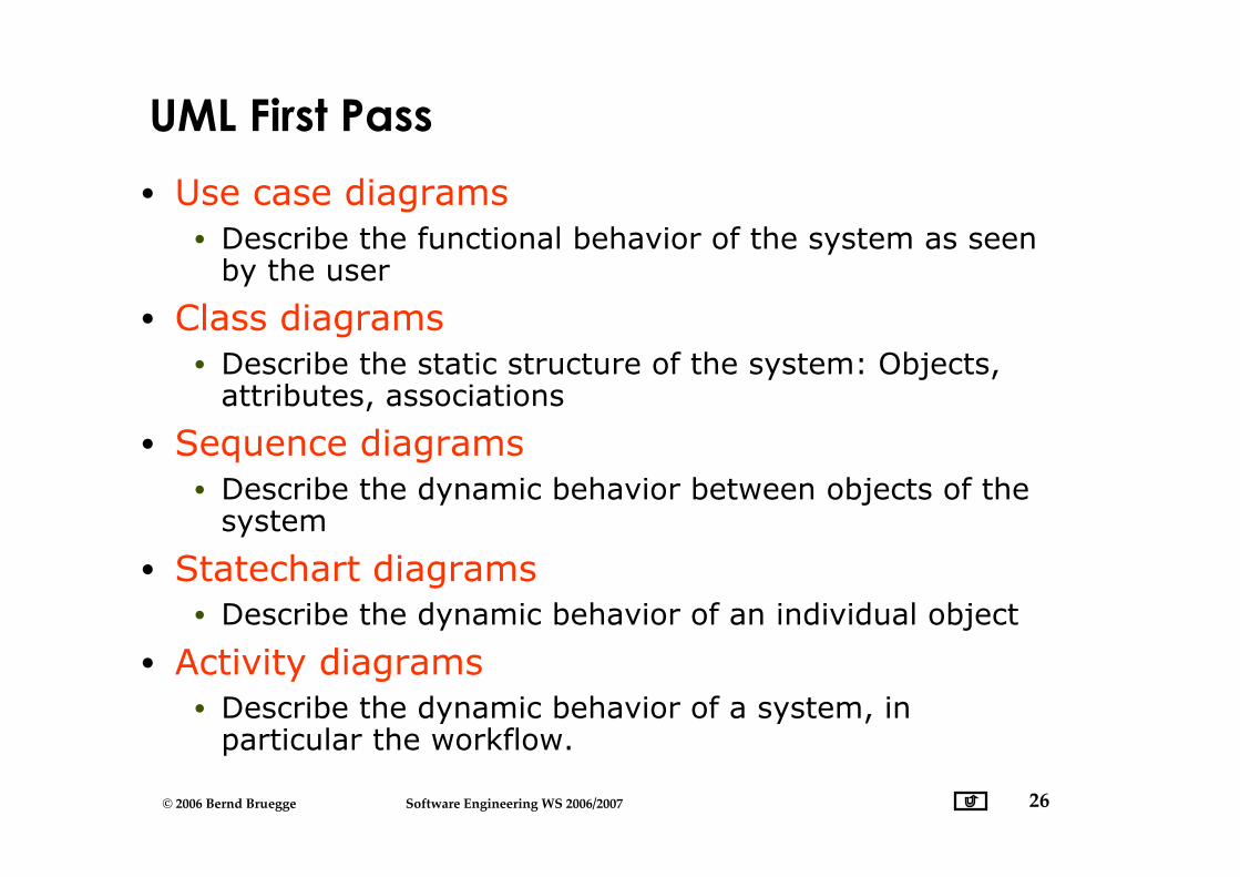
UML First Pass
• Use case diagrams• Describe the functional behavior of the system as seen
by the user
• Class diagrams• Describe the static structure of the system: Objects,
attributes, associations
• Sequence diagrams• Describe the dynamic behavior between objects of the
system
• Statechart diagrams• Describe the dynamic behavior of an individual object
• Activity diagrams• Describe the dynamic behavior of a system, in
particular the workflow.
27© 2006 Bernd Bruegge Software Engineering WS 2006/2007
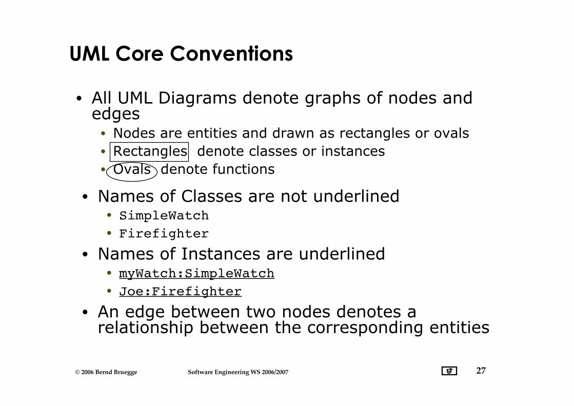
UML Core Conventions
• All UML Diagrams denote graphs of nodes andedges• Nodes are entities and drawn as rectangles or ovals• Rectangles denote classes or instances• Ovals denote functions
• Names of Classes are not underlined• SimpleWatch• Firefighter
• Names of Instances are underlined• myWatch:SimpleWatch• Joe:Firefighter
• An edge between two nodes denotes arelationship between the corresponding entities
28© 2006 Bernd Bruegge Software Engineering WS 2006/2007
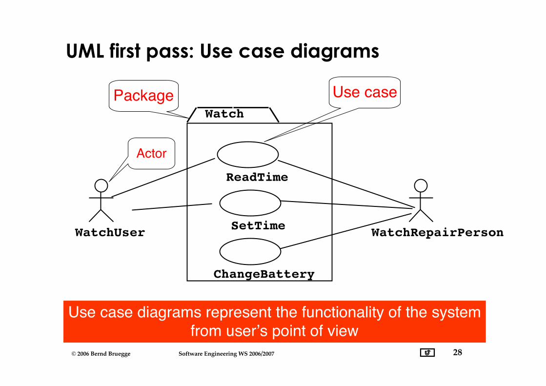
UML first pass: Use case diagrams
WatchUser
Actor
Use casePackage Watch
Use case diagrams represent the functionality of the systemfrom user’s point of view
ReadTime
SetTime
ChangeBattery
WatchRepairPerson
29© 2006 Bernd Bruegge Software Engineering WS 2006/2007
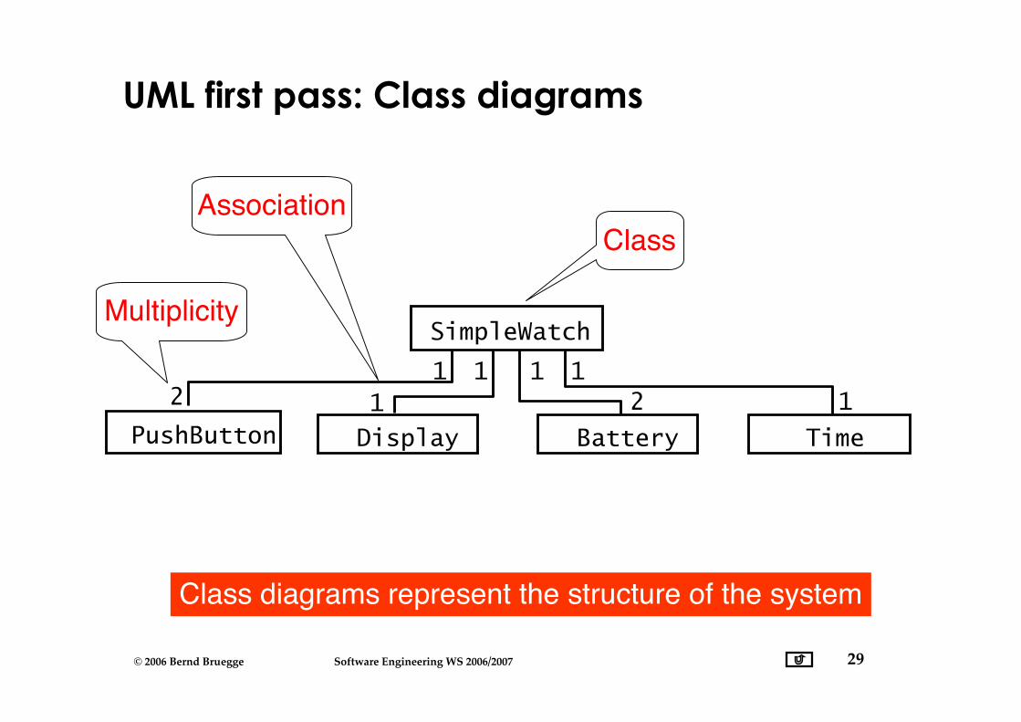
UML first pass: Class diagrams
ClassAssociation
Multiplicity
Class diagrams represent the structure of the system
21 1
11
11
2
SimpleWatch
Display Battery TimePushButton
30© 2006 Bernd Bruegge Software Engineering WS 2006/2007
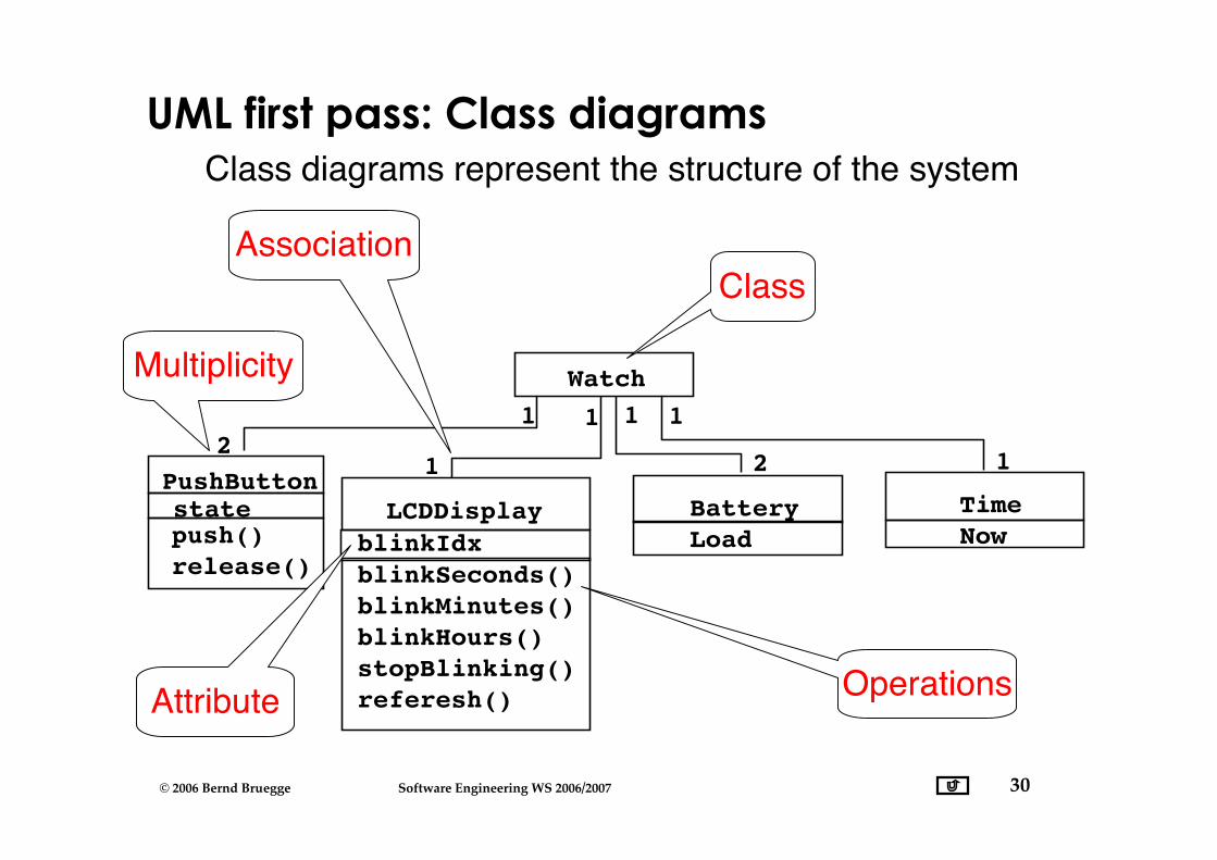
UML first pass: Class diagrams
12
push()release()
1
1
blinkIdxblinkSeconds()blinkMinutes()blinkHours()stopBlinking()referesh()
LCDDisplay BatteryLoad
1
2
1
TimeNow
1
Watch
Operations
statePushButton
Attribute
Class diagrams represent the structure of the system
ClassAssociation
Multiplicity
31© 2006 Bernd Bruegge Software Engineering WS 2006/2007
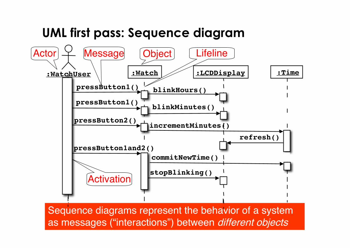
Message
UML first pass: Sequence diagram
:Time :Watch:WatchUser
Object
Activation
Sequence diagrams represent the behavior of a systemas messages (“interactions”) between different objects
Actor
pressButton1()
Lifeline
blinkHours()
pressButton2()incrementMinutes()
:LCDDisplay
pressButton1and2()commitNewTime()
stopBlinking()
refresh()
pressButton1()blinkMinutes()
32© 2006 Bernd Bruegge Software Engineering WS 2006/2007
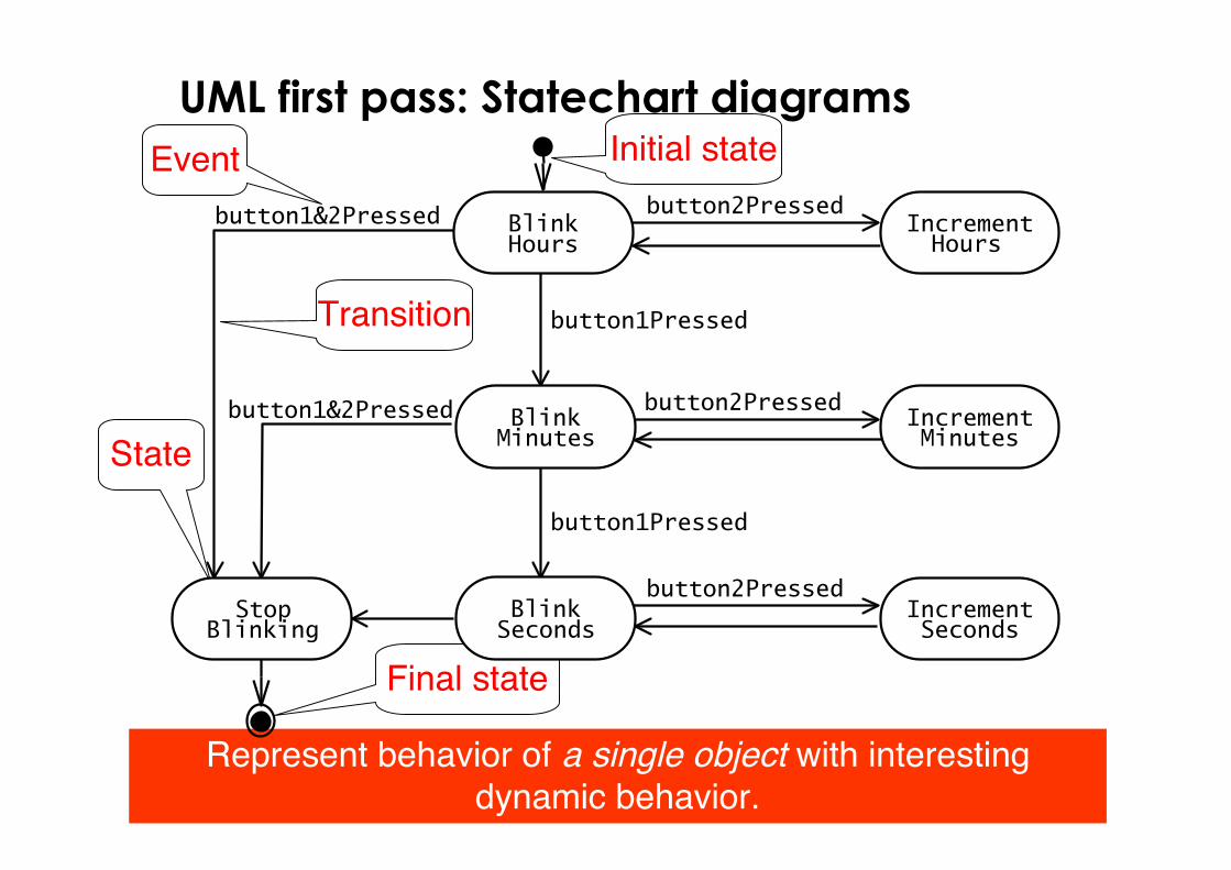
UML first pass: Statechart diagrams
State
Initial state
Final state
Transition
Event
Represent behavior of a single object with interestingdynamic behavior.
button1&2Pressed
button1Pressed
button2Pressed
button2Pressed
button2Pressed
button1Pressed
button1&2Pressed IncrementMinutes
IncrementHours
BlinkHours
BlinkSeconds
BlinkMinutes
IncrementSeconds
StopBlinking
33© 2006 Bernd Bruegge Software Engineering WS 2006/2007
Other UML Notations
UML provides many other notations
• Activity diagrams for modeling work flows• Deployment diagrams for modeling
configurations (for testing and releasemanagement)
34© 2006 Bernd Bruegge Software Engineering WS 2006/2007
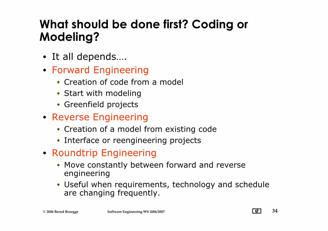
What should be done first? Coding orModeling?
• It all depends….• Forward Engineering
• Creation of code from a model• Start with modeling• Greenfield projects
• Reverse Engineering• Creation of a model from existing code• Interface or reengineering projects
• Roundtrip Engineering• Move constantly between forward and reverse
engineering• Useful when requirements, technology and schedule
are changing frequently.
35© 2006 Bernd Bruegge Software Engineering WS 2006/2007
UML Basic Notation Summary
• UML provides a wide variety of notations formodeling many aspects of software systems
• For now we have concentrated on a fewnotations:• Functional model: Use case diagram• Object model: Class diagram• Dynamic model: Sequence diagrams, statechart
36© 2006 Bernd Bruegge Software Engineering WS 2006/2007
Additional References
• Martin Fowler• UML Distilled: A Brief Guide to the Standard Object
Modeling Language, 3rd ed., Addison-Wesley, 2003.
• Grady Booch,James Rumbaugh,Ivar Jacobson• The Unified Modeling Language User Guide, Addison
Wesley, 1999
• Commercial UML tools• Rational Rose XDE for Java
• http://www-306.ibm.com/software/awdtools/developer/java/
• Together (Eclipse, MS Visual Studio, JBuilder)• http://www.borland.com/us/products/together/index.html
• Open Source UML tools• http://java-source.net/open-source/uml-modeling• ArgoUML,UMLet,Violet, …