Embed Size (px)
Citation preview

170 Iranian Journal of Electrical & Electronic Engineering, Vol. 13, No. 2, June 2017
Modelling and Simulation of a Transformer With Inter-turn
Fault Including Saturation Effect and Variable Fault
Parameters
M. Samami*, H. Yaghobi**(C.A.) and M. Niaz Azari***
Abstract: This investigation deals with a mathematical model for a distribution transformer
including saturation effect. To this end, the equations related to a three phase transformer
are specified and the effect of an inter-turn fault is included. Naturally by applying an inter-
turn fault the inductance and resistance matrix will change. Thus, unknown quantities of
inductances and resistances for completing the matrix are calculated and the inputs, outputs
and state variables are specified. All the equations will be rewritten in terms of state
variables, subsequently saturation effect is added to the model. Finally the block diagram of
the specified model based on the obtained equations are designed and the ultimate model is
simulated. The saturation effect, added to the mathematical model and also the variable
fault parameters are known as two significant contributions which distinguish this study
from other investigations. Various results obtained from the simulation of the final model
confirm the changes in the behavior of faulty transformer such as: a large circulating
current flowing in the shorted turns, lower impact on terminal voltages and currents, a
sudden increase in current flowing in the primary winding, asymmetrical flux distribution
and inverse proportion of the fault severity and the limiting resistor.
Keywords: Inductance, Inter-turn, Modelling, Saturation Effect, Transformer.
1 Introduction 1
1.1 Transformer Fault Classification
transformer as a vital part of a power system, plays
an important role in the transmission process of
generated energy in power plants and distribution of it
to a point of power utilization. In today's world, due to
the incremental rate of complex loads in power
networks with various control systems which causes an
amazing network expansion, transformers are seriously
and continuously exposed to risks. This fact is the main
reason that necessitates the Recognition; classification
and urgent detection of transformer faults. Accordingly,
the faults can be categorized as external and internal [1].
The external faults involve; overloading, voltage
increase due to impulse excitation, short circuit in the
network and etc. Whereas, the internal faults involve;
Iranian Journal of Electrical & Electronic Engineering, 2017.
Paper first received 07 Septempber 2016 and in revised form 10 April
2017.
* The author is with Mah Taab Caspian Electricity Generation
Company, Nowshahr Power Plant, Nowshahr, Iran.
E-mail: [email protected].
** The author is with the Faculty of Electrical and Computer
Engineering, Semnan University, Semnan, Iran.
E-mail: [email protected].
*** The author is with the Faculty of Electrical Engineering,
University of Science and Technology of Mazandaran, Behshahr, Iran.
E-mail: [email protected].
Corresponding Author: H. Yaghobi.
winding defects, winding insulation failures, oil
decomposition, core faults, defects in the mechanism of
tap-changer and etc. Among all the mentioned faults,
winding insulation failures are always considered as the
most important reason of power transformer outage,
which are usually categorized as static and dynamic
failures [2], [3]. The reason of static failure is winding
insulation defect during manufacturing. But the
important factors that cause dynamic failures include;
over voltages caused by lightning, over voltages caused
by switching, inrush current of transformers, prolonged
overloading and failure of the cooling mechanism.
Inter-turn fault is known as a famous reason of
insulation failure in transformers. Transient over
voltages, caused by impulse excitation, is a
determinative factor in creation of winding inter-turn
fault. Thus, overvoltage distribution along the winding
must be uniform [4]. It should be noted that, urgent
detection of inter-turn fault has a great importance in
preventing the increment of fault severity [5].
1.2 Literature Review and Contribution
Various methods have been proposed in order to
detect inter-turn fault which are completely mentioned
in Table 1. On the other hand, the disadvantages of the
applied methods are presented in Table 2.
In [22], [23], the behavior of transformers are
analyzed with high emphasis on experimental models.
A
Dow
nloa
ded
from
ijee
e.iu
st.a
c.ir
at 1
4:20
IRD
T o
n F
riday
Jun
e 15
th 2
018
[ D
OI:
10.2
2068
/IJE
EE
.13.
2.17
0 ]

Iranian Journal of Electrical & Electronic Engineering, Vol. 13, No. 2, June 2017 171
Table 1 Description of some important methods for internal fault detection.
Methods Ref. Remarks and essential descriptions
Differential
Protection
[1], [6], [7]
[1], [6], [7]
Differential relays measure the primary and secondary phase current of the transformer and
convert them to a mutual base value which is comparable with the calculated differences
in the currents.
Small current differences indicates the normal operation of the transformer and also external
fault occurrence condition. This small value is equal to the magnetizing and also the core
loss of the current. But this difference value becomes greater during an internal fault.
Dissolved
Gas Analysis
(DGA)
[8], [9]
[10], [11]
Transformer oil and its winding insulation can be destructed and decomposed to different
gases due to thermal or electrical stress. A range of generated amount of gases between 0-
500 ppm, shows the normal operation of transformer.
The high amount of circulating current caused by an internal fault can be detected with
obtained DGA data, applied by various methods such as Rogers Ratio method.
Frequency
Response
Analysis
(FRA)
[12]- [14]
[15]
[16], [17]
Due to high dependency of winding admittance to the operating frequency, the FRA is
introduced as another method for detection of inter-turn fault. In this method the
admittance is measured in a wide range of frequency.
The responses in this method are categorized as low, medium and high frequency response.
But only low and high frequency responses are considered to be significant in frequency
analysis of inter-turn faults.
This method can also be used in order to detect deformation of windings due to short circuit
fault, and also diagnosis of core fault.
Advanced
Methods
[18]- [20]
[21]
These methods include
Wavelet transform and Artificial neural networks
Fuzzy logic
Table 2 The disadvantages of the mentiond method for internal fault detection.
Methods Disadvantages
Differential
protection
The differential method has high sensitivity to measurement accuracy of the current transformers.
Therefore an algorithm for compensation of measurement through mathematical fault correction,
generated by current transformers, is always needed.
Inaccessibility to phase terminals in the transformers with delta connections for measurement of the
phase currents
Dissolved gas
analysis (DGA)
(DGA)
The results and forecasts derived from dissolved gas analysis method such as local overheating and
high circulating current can also be created by other internal faults in addition to inter-turn fault.
Therefore, this method can cause ambiguity in determining the precise type of fault.
This method is not suitable for dry transformers, transformers with a natural cooling mechanism and
transformers with air forced cooling mechanism.
frequency response
analysis (FRA)
FRA always requires additional equipment for diagnosis.
The prediction of operating conditions is not easily possible due to complex admittances, and always
requires an expert’s opinion and evidential reasons.
Advanced methods
These methods are not practical. As an example, in artificial neural networks the neural current is not
easily available for transformers. Besides, advanced calculation methods always require a large
number of powerful processors.
But considering the high price of transformers and
difficult accessibility to the equipment required for
performing the experiment, this method is not feasible
for everyone. Furthermore, analyzing inter-turn fault
effects, on accessibility to the equipment required for
performing the experiment, this method is not feasible
for everyone. Furthermore, analyzing inter-turn fault
effects, on transformers with different characteristics
and in different voltage levels requires multiple
experimental models which is illogical from economic
point of view. In [24], a model based on flux
rearrangement around the damaged turns has been
developed. But the mentioned model is very simple and
only simulated a single phase transformer. On the other
hand, it does not have transformative fault parameters
including changeable fault resistance and also
changeable number of faulty turns of transformer
winding. Ref. [22], [25], [26], present a finite element
model (FEM) of a transformer in addition to an
experimental model. The various aforementioned
models of the transformer, with inter-turn fault, are
based on finite element analysis, mathematical model
without consideration of saturation effect and also
limited experimental models in accordance to the
specifications of the transformer which are given in the
transformer plaque. In fact, none of the published papers
have presented a flexible model, based on mathematical
equation, considering linkage and leakage flux of the
transformer (changeable self and mutual inductances).
On the other hand, the aforementioned models do not
Dow
nloa
ded
from
ijee
e.iu
st.a
c.ir
at 1
4:20
IRD
T o
n F
riday
Jun
e 15
th 2
018
[ D
OI:
10.2
2068
/IJE
EE
.13.
2.17
0 ]

172 Iranian Journal of Electrical & Electronic Engineering, Vol. 13, No. 2, June 2017
have flexibility for different fault severity. Therefore,
providing a transformer approximate model including
inter-turn fault which can operate under
different nominal specification of the transformer
different winding resistance and inductances
(changeable resistance and also self and mutual
inductances)
various fault resistance and fault severity (the
ability to present an acceptable flux analysis)
various involved number of turns in the faulty
winding
selective fault in each section of each winding
consideration of the core saturation effect
seems to be essential.
The mentioned model is proposed to achieve a better
understanding from the behavior of distribution
transformers with inter-turn fault in a frame of a flexible
model based on mathematical equations, with the ability
to change the fault parameters including fault severity
and the number of shorted turns of the primary winding.
Different parameters of transformer such as voltage,
frequency, inductance, resistance and etc are
changeable. It should be noted that, the saturation effect
is included in the model as well. This paper is based on
mathematical equations of a transformer with inter-turn
fault. Therefore, the passive parameters, caused by
inter-turn fault, should be specified. Then, the equations
are rewritten according to new status, considering the
saturation effect. Finally the obtained block diagram of
the specified model is designed and simulated.
2 Three-Phase Transformer Model, with Inter-turn
Fault
A sample model for a normal 3-phase transformer is
well known [27]. The resistance and inductance matrix
for a normal operated 3-phase transformer are also
presented in [27]. Imposing an inter-turn fault to phase
‘B’ of the transformer primary winding divides the
mentioned coil into two segments including sub-coils
‘a’, and ‘sh’, as shown in Fig. 1, [27].
1
2
4
5
6
0 0 0 0 0 0
0 0 0 0 0 0
0 0 0 0 0 0
0 0 0 0 0 0
0 0 0 0 0 0
0 0 0 0 0 0
0 0 0 0 0 0
a
sh
r
r
r
r r
r
r
r
(1)
11 12 1 1 14 15 16
21 22 2 2 24 25 26
1 2 4 5 6
1 2 4 5 6
41 42 4 4 44 45 46
51 52 5 5 54 55 56
61 62 6 6 64 65 66
a sh
a sh
a a aa ash a a a
sh sh sha shsh sh sh sh
a sh
a sh
a sh
L L L L L L L
L L L L L L L
L L L L L L L
L L L L L L LL
L L L L L L L
L L L L L L L
L L L L L L L
As a result, the resistance and inductance matrix will
change to, 7*7 matrix with unknown parameters as
shown in (1). It should be stated that, the quantities of
the faulty sub-coil, are shown with, ‘sh’ index and the
red colored parameters are known as passive parameters
which should be calculated subsequently.
Fig. 1 Inter-turn fault modelling in a distribution transformer [28].
2.1 Determination of inductances and resistances
Passive resistance quantities depend on the ratio
between, the number of turns in each sub-coil to the
general number of turns in the faulty (primary) winding
[27]. The unknown quantities of inductance matrix are
specified by three important rules including:
consistency, proportionality and leakage [27]. It is
necessary to mention that, leakage factors, such as
,, andash shiσ σ σai
are considered as known parameters.
In fact, leakage factors have a strong relationship with
the geometry of transformers and it is the main reason
which makes these factors hard to obtain. However, the
leakage factors can be approximated by neglecting the
leakage flux outside the windings and assuming it to
flow completely parallel to the axis of transformer
windings [29].
Each winding inductance consists of, self and mutual
inductance. For instance:
(2)
aa La maL L L
33 3 3 L mL L L
shsh Lsh mshL L L
In accordance to the mentioned rules, the unknown
self and mutual inductances of the inductance matrix are
calculated by a numerical resolution method, as follows:
(3)
2
33
3
*
a
aa
nL L
n
Consequently, shshL can be obtained by replacing shn
Dow
nloa
ded
from
ijee
e.iu
st.a
c.ir
at 1
4:20
IRD
T o
n F
riday
Jun
e 15
th 2
018
[ D
OI:
10.2
2068
/IJE
EE
.13.
2.17
0 ]

Iranian Journal of Electrical & Electronic Engineering, Vol. 13, No. 2, June 2017 173
instead of an in (3).
(4)
33
3 3
*
a sh
ash sha
sh sh
aa La ma
a a
n nL L L
n n
n nL L L
n n
But other inductances including, mutual inductances
among the sub-coils of faulty winding in phase ‘B’, and
other windings are still unknown, which are calculated
by assuming:
(5) ai a
shi sh
L nk
L n
Thus, the mentioned inductances are given by:
(6) 3
311
a a
sh sh a
ai ia i
a sh a
sh sh
n n
n n nkL L L
n n nk n
n n
(7) 3
3
1 1
11
sh
shi ish i
a
sh
nL L L
nk n
n
However, by assuming a typical winding to be wound
on the same leg as the sub-coils of faulty (phase ‘B’ of
primary) winding, the equations will be different for
that. In this method the sub-coil of the faulty winding
which has the largest number of turns will be selected.
Suppose, sub-coils ‘a’ has the largest number of turns
between two sub-coils. As a result, the following
equation is specified.
(8) 3
ai
i
As mentioned before, different leakage factors such
as 3, and ai shi i are assumed to be known. Thus,
for obtaining the unknown inductances, the following
formula is obtained.
(9) 33
3 2
33 3
11aa i
ai ia i
i
L L LL L L
L L
And as a result of consistency principle shiL can be
calculated as follows.
(10) 3 shi i aiL L L
2.2 Voltage Equations
The faulty phase voltage equations of the primary
winding, considering an inter-turn fault occurred on
phase ‘B’, with certain number of turns which is shown
by ,shn can be written as
(11) 3 a a f a circulating av r i z i i p
(12) sh sh sh shv r i p
where fz is the fault impedance, circulatingi is the
circulating current caused by inter-turn fault in the
shorted turns, shv and shr represent the voltage and the
resistance of the shorted turns, respectively, and
/ .p d dt
The voltage equations for healthy windings
in both primary and secondary sides in phase ‘A’ can be
written as follows.
(13) 1 1 1 1 v r i p
(14) ´ ´ ´ ´
2 2 2 2 v r i p
Equations of healthy windings in phase ‘B’ and ‘C’
can be written in the same way as above. By taking a
look at the voltage equations, the induced voltage terms
including, 1, , a shp p p and´
2p can be seen
obviously. All the induced voltage terms depend on
inductances. Besides, after the occurrence of an inter-
turn fault the inductance matrix will change, which
involves known and unknown arrays. Thus, for
completing the voltage equations in details, the
unknown quantities should be rewritten based on the
known inductances and considering three important
rules including consistency, leakage and proportionality,
as mentioned before.
2.3 Determination of the Induced Voltage Equations
By assuming
(15)
1 3 5 n n n
2 4 6 n n n
The first induced voltage term of faulty winding is
ap which can be written, based on 3LL and 3mL . For
this purpose, the flux equation should be written based
on the flux matrix as follows:
(16) 1 1 2 2 4 4
5 5 6 6
a a a aa a ash sh a
a a
L i L i L i L i L i
L i L i
In the next step, the unknown inductances will be
replaced in accordance to (3)-(10), as expressed below.
(17)
2
3
3 3 3
2´
1 2
3 3 3 3 33
´ ´
4 5 6
3 3 3
a a sh
a L a sh
a a a a sh
a sh
m
a a a
n n nL i i
n n n
n n n n ni i i i
n n n n nL
n n ni i i
n n n
Finally, derivative of (17), represents the induced
voltage of sub-coil ‘a’, and will be written as
Dow
nloa
ded
from
ijee
e.iu
st.a
c.ir
at 1
4:20
IRD
T o
n F
riday
Jun
e 15
th 2
018
[ D
OI:
10.2
2068
/IJE
EE
.13.
2.17
0 ]
174 Iranian Journal of Electrical & Electronic Engineering, Vol. 13, No. 2, June 2017
(18)
2
3
3 3 3
´ 2
1 2
3 3 3 3 3
3 ´´
5 64
3 3 3
a a a sh sh
a a L
a a a a a sh sh
m
a a a
n di n n die p L
n dt n n dt
n n n di n n didi d i
n dt n dt n dt n n dtL
n n di n d id i
n dt n dt n dt
The second induced voltage term of the faulty
winding is, shp which can be calculated in the same
way as ap . The final equation will be as follows
(19)
2
3
3 3 3
´ 2
1 2
3 3 3 3 3
3 ´´
5 64
3 3 3
sh sh sh a a
sh sh L
sh sh sh sh sh a a
m
sh sh sh
n di n n die p L
n dt n n dt
n n n di n n didi d i
n dt n dt n dt n n dtL
n n di n d id i
n dt n dt n dt
The induced voltage of phase ‘A’ and ‘C’, in the
primary winding can be obtained with the same process,
as mentioned for the sub-coils of the faulty winding.
The induced voltage of phase ‘A’ is calculated from
flux equation as follows.
(20) 1 11 1 12 2 1 1 14 4
15 5 16 6
a a sh shL i L i L i L i L i
L i L i
The following equations are obtained, According to
Ref. [29].
(21) 1 1
1
i
i m
nL L
n
(22)
2
1 1
2 2
m
m
L n
L n
With the help of (2) and (21), the flux equation becomes
(23)
´
1 2
1 11 1 1 1
´ ´
4 5 6
a sh
a sh
L m
n ni i i i
n nL i L
i i i
The derivative of (23), represents the induced voltage
of phase ‘A’ in primary winding as follows:
(24)
´
1 2
1 1 11 1 1 1
´ ´
4 5 6
a a sh sh
L m
di d i n di n di
di dt dt n dt n dte p L L
dtd i di d i
dt dt dt
Considering, 1 3 5 m m mL L L
and also
2 4 6 m m mL L L , The ultimate induced voltage
equation of phase ‘C’, can be written with the same
process, as phase ‘A’. For completing (14) which is
known as the secondary voltage equation of phase ‘A’,
the secondary induced voltage including, ´
2p , should
be calculated. The induced voltage of the mentioned
phase in secondary side is calculated from the flux
equation as
(25) 2 21 1 22 2 2 2 24 4
25 5 26 6
a a sh shL i L i L i L i L i
L i L i
The unknown parameters of (25) is calculated in
accordance to (3)-(10), as previously mentioned and the
equation becomes
(26)
1
1 2
2 2 2
2 2 2 2
5 64
4 5 6
2 2 2
a sh
a sh
L m
n nni i i i
n n nL i L
n nni i i
n n n
With the help of the equations which are used for
referring the quantities of winding secondary side, to
winding primary side [29], and by multiplying both
sides of (26) by 2 1/ ,n n the following equation is
obtained.
(27)
´ ´ ´2
´ 1 2 4 5 62 2
2 2 2 12 2
1 1
2 1 2 1
L ma sh
a sh
i i i i in n
L i L n nn nn n i in n n n
By dividing both sides of (27) to 2
2 1/n n , the
final flux equation can be written as
(28)
´
´ ´ ´ 1 2
1 12 2 2 1
´ ´
4 5 6
a sh
a sh
L m
n ni i i i
n nL i L
i i i
The derivative of (28), represents the induced voltage
of phase ‘A’, in secondary winding as follows:
(29)
´
1 2´´
2 1 12 2 1
´´
5 64
a a sh sh
L m
n di n didi d i
d i dt dt n dt n dte L L
dtdi d id i
dt dt dt
The induced voltages of phase ‘B’ and ‘C’ in
secondary winding side, are obtained the same as phase
‘A’ and in accordance to (25)-(29). It is worth noting
that, the first term of all induced voltage equations
shows the leakage inductance, and the second term of
the mentioned equations presents the core model.
2.4 Simulation of Three-Phase Transformer
As mentioned earlier, for simulation of 3- phase
transformer with inter-turn fault, specification of input,
output and state variables are needed. In this simulation
voltages are considered as input, currents are considered
as output and the total flux is used as state variable. The
total flux linkages of windings are known as state
variables. Thus we have 7 state variables. In terms of
these 7 state variables, the voltage equation of the faulty
winding can be rewritten as follows:
Dow
nloa
ded
from
ijee
e.iu
st.a
c.ir
at 1
4:20
IRD
T o
n F
riday
Jun
e 15
th 2
018
[ D
OI:
10.2
2068
/IJE
EE
.13.
2.17
0 ]

Iranian Journal of Electrical & Electronic Engineering, Vol. 13, No. 2, June 2017 175
(30) 3
1 a
a a f a circulating
b
dv r i z i i
dt
(31) 1
sh
sh sh sh
b
dv r i
dt
It is noteworthy that, other voltage equations can be
rewritten in the same way. As previously mentioned,
(17) represents the related flux of sub-coil ‘a’ in the
faulty winding in primary. By rewriting (17), based on
, the following relation is obtained.
(32)
2
3
3 3 3
2´
1 2
3 3 3 3 33
´ ´
4 5 6
3 3 3
a a sh
a L a sh
a a a a sh
a sh
m
a a a
n n nx i i
n n n
n n n n ni i i i
n n n n nx
n n ni i i
n n n
where a b a , and b is the base frequency which
is used for reactance calculation. It is noteworthy that,
sh is also obtained in the same way. By rewriting (23)
and (28) for two other windings, both in primary and
secondary sides in a similar way, based on , the
following formulas are obtained.
(33)
´ ´
1 2 4
1 11 1 1 1
´
5 6
a sh
a sh
L m
n ni i i i i
n nx i x
i i
(34)
´ ´
´ ´ ´ 1 2 4
1 12 2 2 1
´
5 6
a sh
a sh
L m
n ni i i i i
n nx i x
i i
The final rewritten equations for other phases, both in
primary and secondary can be obtained the same as (33)
and (34). The second term of (33) and (34), is related to
the magnetizing inductance of healthy windings. It can
be expressed as
(35) ´ ´ ´
1 1 2 4 5 6
1 1
a sh
m m a sh
n nx i i i i i i i
n n
Equation (36) and (37) are related to the magnetizing
inductance of sub-coils ‘a’ and ‘sh’ in primary,
respectively. They can be written as
(36)
´ ´
1 2 4
1 1_ 1
´3
5 6
a sh
a sha
m a m
n ni i i i in n nx
ni i
(37)
´ ´
1 2 4
1 1_ 1
´3
5 6
a sh
a shsh
m sh m
n ni i i i in n nx
ni i
The minimum shorted turns in the faulty winding will
cause the highest circulating current. Since, in such
situation, an is usually close to 3n , it is assumed that,
_ m m a . Thus, we can use (35) instead of (36). The
ratio between the linkage flux, passes through the core
inside the shorted turns and the same flux passes
through the middle of the transformer core inside the
healthy turns can be written as follows.
(38) _
3
m sh sh
m
n
n
According to (37) and (38) and by assuming a
constant supply voltage, occurrence of an inter-turn
fault causes decrement of the flux density, flowing
through the core, inside the faulty turns. On the other
hand, this issue leads to an enhancement of flux density
outside the faulty area. The main reason of this
phenomenon is the high leakage flux, surrounding the
shorted turns unlike the lower amount of flux inside
them. In this situation, due to constant supply voltage
the fundamental linkage flux does not vary, but a major
amount of that, passes the same as leakage flux in a
radial form, around the shorted turns and naturally, the
leakage flux around these turns becomes stronger,
exactly unlike the flux flowing through the core inside
the faulty turns [22]. So, by considering (35) and (37)
and in accordance to the flux equations, which were
previously rewritten, the compact flux equations in the
faulty winding and also healthy windings of a sample
phase, both in primary and secondary side can be
written as
(39)
2
3
3 3 3
a a sh
a L a sh m
n n nx i i
n n n
(40)
2
3 _
3 3 3
sh sh a
sh L sh a m sh
n n nx i i
n n n
(41) 1 1 1 L mx i
(42) ´ ´ ´
2 2 2 L mx i
The flux equations of other healthy windings are the
same as (41) and (42). Thus the currents which are
known as outputs of our simulation can be calculated
with the help of (39)-(42), and ultimately by substituting
the obtained current equations into (35) and by
assuming 3
ζan
n , (35) becomes
(43)
´
1 2
´
1 32
1 ´´
5 64
´ ´
54 6
a mm m
L LL
m m
m mm
LL L
x xx
x
xx x
Equation (43) can be written more compactly as
Dow
nloa
ded
from
ijee
e.iu
st.a
c.ir
at 1
4:20
IRD
T o
n F
riday
Jun
e 15
th 2
018
[ D
OI:
10.2
2068
/IJE
EE
.13.
2.17
0 ]
176 Iranian Journal of Electrical & Electronic Engineering, Vol. 13, No. 2, June 2017
(44)
´´ ´
5 61 2 4
´ ´ ´
1 3 52 4 6
a
m M
L L LL L L
xx x x
x x x
´ ´ ´
1 1 3 52 4 6
1 1 1 1 1 1 1 1
M m L L LL L L
x x x x xx x x
Basically, there are different methods for adding
saturation to the mentioned simulated model of the 3-
phase transformer including inter-turn fault. In this
paper, a relation between the saturated and the linear
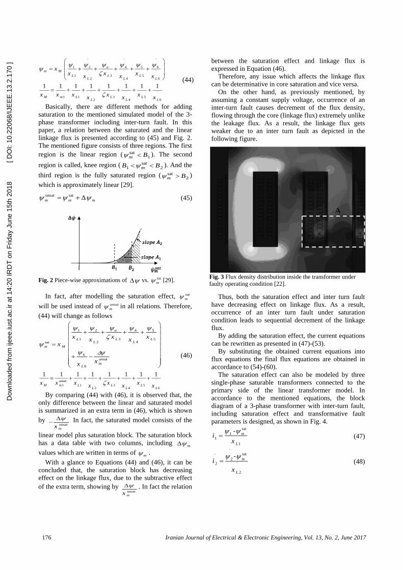
linkage flux is presented according to (45) and Fig. 2.
The mentioned figure consists of three regions. The first
region is the linear region ( sat1m B ). The second
region is called, knee region ( sat1 2 mB B ). And the
third region is the fully saturated region ( sat2m B )
which is approximately linear [29].
(45) unsat sat m m m
Fig. 2 Piece-wise approximations of vs. sat
m [29].
In fact, after modelling the saturation effect, sat
m
will be used instead of unsat
m in all relations. Therefore,
(44) will change as follows
(46)
´ ´
51 2 4
´ ´
1 3 52 4sat
´
6
´
6
a
L L LL L
m M
unsat
mL
x x xx x
x
xx
Δ
´ ´ ´
1 3 512 4 6
1 1 1 1 1 1 1 1
unsat
M L L LmL L L
x x x xxx x x
By comparing (44) with (46), it is observed that, the
only difference between the linear and saturated model
is summarized in an extra term in (46), which is shown
by unsat
mx
In fact, the saturated model consists of the
linear model plus saturation block. The saturation block
has a data table with two columns, including m
values which are written in terms of m .
With a glance to Equations (44) and (46), it can be
concluded that, the saturation block has decreasing
effect on the linkage flux, due to the subtractive effect
of the extra term, showing by unsat
mx
. In fact the relation
between the saturation effect and linkage flux is
expressed in Equation (46).
Therefore, any issue which affects the linkage flux
can be determinative in core saturation and vice versa.
On the other hand, as previously mentioned, by
assuming a constant supply voltage, occurrence of an
inter-turn fault causes decrement of the flux density,
flowing through the core (linkage flux) extremely unlike
the leakage flux. As a result, the linkage flux gets
weaker due to an inter turn fault as depicted in the
following figure.
Fig. 3 Flux density distribution inside the transformer under
faulty operating condition [22].
Thus, both the saturation effect and inter turn fault
have decreasing effect on linkage flux. As a result,
occurrence of an inter turn fault under saturation
condition leads to sequential decrement of the linkage
flux.
By adding the saturation effect, the current equations
can be rewritten as presented in (47)-(53).
By substituting the obtained current equations into
flux equations the final flux equations are obtained in
accordance to (54)-(60).
The saturation effect can also be modeled by three
single-phase saturable transformers connected to the
primary side of the linear transformer model. In
accordance to the mentioned equations, the block
diagram of a 3-phase transformer with inter-turn fault,
including saturation effect and transformative fault
parameters is designed, as shown in Fig. 4.
(47)
sat
1
1
1
- m
L
ix
(48)
´sat´
2
2 ´
2
- m
L
i
x
Dow
nloa
ded
from
ijee
e.iu
st.a
c.ir
at 1
4:20
IRD
T o
n F
riday
Jun
e 15
th 2
018
[ D
OI:
10.2
2068
/IJE
EE
.13.
2.17
0 ]

Iranian Journal of Electrical & Electronic Engineering, Vol. 13, No. 2, June 2017 177
Fig. 4 The block diagram of 3-phase transformer with inter-turn fault including saturation effect.
(49)
2sat
3
3
a m sh
a sh
a L a
n ni i
n x n
(50)
2sat
3
3
sh m sh a
sh a
sh L sh
n ni i
n x n
(51)
´sat´
4
4 ´
4
m
L
i
x
(52)
sat
5
5
5
m
L
ix
(53)
´sat´
6
6 ´
6
m
L
i
x
(54)
sat
1
1 1 1
1
m
b
L
v r dtx
(55)
´sat´ ´ ´
2
2 2 2 ´
2
m
b
L
v r dt
x
(56)
2sat
3
3
a m sh
a b a a sh
a L a
n nv r i dt
n x n
(57)
2sat
3
3
sh m sh a
sh b sh sh a
sh L sh
n nv r i dt
n x n
(58)
´sat´ ´ ´
4
4 4 4 ´
4
m
b
L
v r dt
x
(59)
sat
5
5 5 5
5
m
b
L
v r dtx
(60)
´sat´ ´ ´
6
6 6 6 ´
6
m
b
L
v r dt
x
Dow
nloa
ded
from
ijee
e.iu
st.a
c.ir
at 1
4:20
IRD
T o
n F
riday
Jun
e 15
th 2
018
[ D
OI:
10.2
2068
/IJE
EE
.13.
2.17
0 ]
178 Iranian Journal of Electrical & Electronic Engineering, Vol. 13, No. 2, June 2017
3 Simulation Results and Discussion
The model developed, has been simulated and the
following simulation results refer to a 3-phase star-star
transformer with an inter-turn fault, imposing to phase
‘B’ of the transformer primary winding whose
characteristics are given as follows:
Table 3 Three-phase transformer parameters
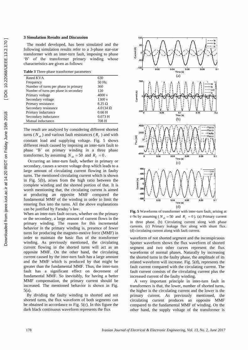
Rated KVA 630 Frequency 50 Hz Number of turns per phase in primary 360 Number of turns per phase in secondary 120 Primary voltage 4000 v Secondary voltage 1300 v Primary resistance 8.25 Ω Secondary resistance 4.0134 Ω Primary inductance 0.66 H Secondary inductance 0.073 H Mutual inductance 708 H
The result are analyzed by considering different shorted
turns ( shN ) and various fault resistances ( fR ) and with
constant load and supplying voltage. Fig. 5 shows
different result caused by imposing an inter-turn fault to
phase ‘B’ on primary winding in a three phase
transformer, by assuming 50shN and 0fR .
Occurring an inter-turn fault, whether in primary or
secondary, causes a severe voltage drop which leads to a
large amount of circulating current flowing in faulty
turns. The mentioned circulating current which is shown
in Fig. 5(b), arises from the high ratio between the
complete winding and the shorted portion of that. It is
worth mentioning that, the circulating current is aimed
at producing an opposite MMF compared the
fundamental MMF of the winding in order to limit the
entering flux into the turns. All the above explanations
can be justified by Faraday’s law.
When an inter-turn fault occurs, whether on the primary
or the secondary, a large amount of current flows in the
primary winding. The reason for this incremental
behavior in the primary winding is, presence of fewer
turns for producing the magneto-motive force (MMF) in
order to maintain the basic flux of the transformer
winding. As previously mentioned, the circulating
current flowing in the shorted turns will act as an
opposite MMF. On the other hand, the circulating
current caused by the inter-turn fault has a large amount
and the MMF which is produced by that might be
greater than the fundamental MMF. Thus, the inter-turn
fault has a significant effect on decrement of
fundamental MMF. So inevitably, for having a better
MMF compensation, the primary current should be
increased. The mentioned behavior is shown in Fig.
5(a).
By dividing the faulty winding to shorted and not
shorted turns, the flux waveform of both segments can
be obtained in accordance to Fig. 5(c). In this figure the
dark black continuous waveform represents the flux
(a)
(b)
(c)
(d)
Fig. 5 Waveforms of transformer with inter-turn fault, arising at
t=9s by assuming ( 50shN and 0f
R ). (a) Primary current
in three phase. (b) Circulating current along with phase
currents. (c) Primary leakage flux along with shunt flux.
(d) circulating current along with fault current.
waveform of not shorted segment and the inconspicuous
Spotter waveform shows the flux waveform of shorted
segment and two other curves represent the flux
waveforms of normal phases. Naturally by increasing
the shorted turns in the faulty phase, the amplitude of its
related waveform will increase. Fig. 5(d), represents the
fault current compared with the circulating current. The
fault current consists of the circulating current plus the
increased current of the faulty winding.
A very important principle in inter-turn fault in
transformers is that, the lower, number of shorted turns,
the higher is the circulating current and the lower is the
primary current. As previously mentioned, the
circulating current produces an opposite MMF
compared to the fundamental MMF of winding. On the
other hand, the supply voltage of the transformer is
Dow
nloa
ded
from
ijee
e.iu
st.a
c.ir
at 1
4:20
IRD
T o
n F
riday
Jun
e 15
th 2
018
[ D
OI:
10.2
2068
/IJE
EE
.13.
2.17
0 ]

Iranian Journal of Electrical & Electronic Engineering, Vol. 13, No. 2, June 2017 179
assumed to be constant. Subsequently the fundamental
MMF of the transformer will not change. Thus, by
increasing the shorted turns, the same opposite MMF
need to be produced, as it used to. As a result, a lower
amount of circulating current is produced. Besides the
incremental behavior of circulating current due to
decreasing of the shorted turns, also refers to reduction
of impedance of the shorted loop. Fig. 6(a) shows the
circulating current with the minimum turn ( 1shN )
which leads to a high amount of current as expected.
Increasing the number of shorted turns will decrease
the number of healthy (not shorted) turns and leads to
enhancement of primary current. Fig. 6(b) shows the
primary current by imposing an inter-turn fault to phase
‘B’ on primary winding in a three phase transformer, by
assuming 75shN and 0fR , which confirms the
incremental behavior of primary current due to
increasing the shorted turns of the faulty winding.
The enhancement of primary current caused by
increasing the shorted turns, can be seen obviously by
comparing Fig. 5(a) and 6(b).
In accordance to Fig. 6(c) and comparing it with Fig.
5(c), the flux enhancement caused by increasing the
shorted turns in the faulty winding which is shown by
the inconspicuous Spotter waveform can be seen
obviously. On the other hand, by increasing the shorted
turns in faulty winding, the healthy turns of this winding
will decrease. As a result, the flux which is produced by
the healthy turns of the faulty winding will decrease as
shown by the dark black continuous waveform in Fig.
6(c).
A very significant parameter for controlling the fault
and the circulating current is the fault resistance which
is naturally caused by insulation defection during the
fault occurrence. By increasing the fault resistance, the
fault and circulating current will decrease. In other
words, the fault severity will decrease. On the other
hand by decreasing the fault resistance, the fault and
circulating current will increase. In other words, the
fault severity will increase. Fig. 7(a) and 7(b) shows
different result caused by imposing an inter-turn fault to
phase ‘B’ on primary winding in a three phase
transformer, by assuming 50shN and 0.25fR .
A comparison between Fig. 5(a) and 5(b) and Fig.
7(a) and 7(b) shows that by increasing the fault
resistance to 0.25, while we have 50 shorted turns, the
primary current will decrease approximately from 80 to
70. On the other hand the circulating current will
decrease approximately from 480 to 400 and as a result
the fault current will decrease approximately from 560
to 470.
Fig. 7(c) and 7(d) shows different result caused by
imposing an inter-turn fault to phase ‘B’ on primary
winding in a three phase transformer, by assuming
50shN and 0.5fR . In this model we increase the
fault resistance from 0.25 to 0.5. Reducing the fault
……
(a)
(b)
(c)
Fig. 6 Waveforms of transformer with inter-turn fault, arising
at t=9s by assuming ( 1sh
N or 75) and ( 0f
R ).
(a) Circulating current along with fault current. (b) Primary
currents in three phase for ( 75sh
N ) and ( 0f
R ).
(c) Primary leakage flux along with shunt flux for ( 75sh
N )
and ( 0f
R ).
severity after increasing the fault resistance is obvious
by comparing Fig. 7(a) and 7(b) with Fig. 7(c) and 7(d).
Fig. 8(a) is a column chart which shows primary
currents, considering different fault parameters
including variable shorted turns and fault resistances. As
already proved, the enhancement of shorted turns in
faulty winding will decrease the circulating current
which leads to an increment in primary current of the
transformer. This figure confirms reducing of fault
severity by increasing the fault resistance in accordance
to previous simulated figures of our model.
Fig. 8(b) is a column chart which represents the flux
in both shorted and healthy turns by changing the
number of shorted turns in the faulty winding. This
column chart is a brief result from the effect of changing
the fault size on flux in the shorted and healthy portion
of the faulty winding which is obtained from the
simulation of our model and confirms the enhancement
of shorted turn flux by increasing the number of shorted
turns and consequently decreasing the flux of healthy
turns in faulty winding by decreasing the number of
healthy turns.
Dow
nloa
ded
from
ijee
e.iu
st.a
c.ir
at 1
4:20
IRD
T o
n F
riday
Jun
e 15
th 2
018
[ D
OI:
10.2
2068
/IJE
EE
.13.
2.17
0 ]

180 Iranian Journal of Electrical & Electronic Engineering, Vol. 13, No. 2, June 2017
(a)
(b)
(c)
(d)
Fig. 7 Waveforms of transformer with inter-turn fault, arising
at t=9s by assuming ( 50sh
N ) and ( 0.25f
R or 0.5).
(a) Primary currents in three phase for ( 50sh
N ) and
( 0.25f
R ). (b) Circulating current along with phase current
for ( 50sh
N ) and ( 0.25f
R ). (c) Primary currents in three
phase for ( 50sh
N ) and ( 0.25f
R ). (d) Circulating
current along with phase currents for ( 50sh
N ) and
( 0.25f
R ).
4 Conclusion
This contribution modeled and consequently
simulated a distribution transformer, based on
mathematical equations both in normal operating
condition and also in the presence of an inter-turn fault.
The saturation effect is also considered in this model,
which is obtained by adding the saturation block to the
linear model of the transformer. The mentioned block is
an approximation of m values, which are written in
(a)
(b)
Fig. 8 Primary current and flux measurement. (a) Primary
current, considering different fault parameters. (b) Flux in
both shorted and healthy turns assuming different shorted
turns.
terms of m . The model has been used to demonstrate
different behaviors of a transformer, considering
alterability in the number of shorted turns in the faulty
winding and also in fault resistance. The mentioned
items are two highlighted distinctions in this study
compared other investigations. The results of
simulations indicate the remarkable ability of the
flexible model to represent the real behavior of a
transformer with an inter-turn fault. The mentioned
results can be written as follows.
Occurrence of an inter-turn fault, whether in primary
or secondary causes a severe circulating current which
leads to an increment in the primary current of the faulty
phase. It was also found that for the faults on the
primary side, the secondary current will remain
unaltered. Increasing the number of shorted turns will
cause flux enhancement of this segment of the faulty
winding. It is noteworthy that, the lower the number of
shorted turns, the higher is the circulating current due to
reduction of impedance of the shorted loop and the
lower is the primary current due to increasing the
number of healthy turns in the faulty winding. Thus, an
inter-turn fault, including a few turns, has negligible
effect on the terminal values of the transformer which
Dow
nloa
ded
from
ijee
e.iu
st.a
c.ir
at 1
4:20
IRD
T o
n F
riday
Jun
e 15
th 2
018
[ D
OI:
10.2
2068
/IJE
EE
.13.
2.17
0 ]

Iranian Journal of Electrical & Electronic Engineering, Vol. 13, No. 2, June 2017 181
makes the fault detection harder. It was also proved that,
by assuming a constant supply voltage, an inter-turn
fault will decrease the flux density passing through the
core, inside the shorted turns and increases the flux
density outside the faulty area. In fact the fundamental
linkage flux remains constant. But it mainly passes in
redial form around the shorted turns which leads to
asymmetrical flux distribution in the transformer.
Finally, the last result which is obtained from the
simulation is the fault severity which can be controlled
by a fault resistance and the number of shorted turns.
The minimum fault resistance causes the maximum
circulating and primary current. On the other hand, the
minimum number of the shorted turns causes the
maximum circulating current and minimum increment
in primary current.
References
[1] R. S. Bhide, M. S. S. Srinivas, A. Banerjee and R.
Somakumar, “Analysis of winding inter-turn fault
in transformer: a review and transformer models,”
IEEE International Conference on Sustainable
Energy Technologies (ICSET), pp. 1-7, 6-9
December, Sri Lanka, 2010.
[2] Rajamani.P, Debangshu Dey and Sivaji Chakravorti,
“Cross-correlation aided wavelet network for
classification of dynamic insulation failure in
transformer winding during impulse test”, IEEE
Transactions on Dielectrics and Electrical
Insulation, Vol. 18, No. 2, pp. 521-532, April 2011.
[3] Rajamani. P and Sivaji Chakravorti, “Identification
of simultaneously occurring dynamic disc-to-disc
insulation failures in transformer winding under
impulse excitation”, IEEE Transactions on
Dielectrics and Electrical Insulation, Vol. 19, No.
2, pp. 443-453, April 2012.
[4] M. Heidarzadeh and M. R. Besmi, “Influence of the
parameters of disk winding on the impulse voltage
distribution in power transformers”, Iranian
Journal of Electrical & Electronic Engineering
(IJEEE), Vol. 10, No. 2, pp. 143-151, June 2014.
[5] H. Yaghobi, K. Ansari and H. Rajabi Mashhadi,
“Analysis of magnetic flux linkage distribution in
salient- pole synchronous generator with different
kinds of inter- turn winding faults”, Iranian Journal
of Electrical & Electronic Engineering (IJEEE),
Vol. 7, No. 4, pp. 260-272, Dec. 2011.
[6] J. M. Lunsford and T. J. Tobin, “Detection of and
protection for low current winding in overhead
distribution transformers”, IEEE Transactions on
Power Delivery, Vol. 12, No. 3, pp. 1241-1249,
July 1997.
[7] T. S. Sidhu and M. S. Sachdev, “On-line
identification of magnetizing inrush and internal
faults in three-phase transformers”, IEEE
Transactions on Power Delivery, Vol. 7, No. 4, pp.
1885-1891, October 1992.
[8] Selwyn Palmer, “Detection of fault in new and old
transformers by dissolved-gas analysis”, IET Power
Engineering Journal, Vol. 2, No. 1, pp. 52-54, Jan.
1988.
[9] Joseph J. Kelly, “Transformer fault diagnosis by
dissolved-gas analysis”, IEEE Transactions on
Industry Applications, Vol. IA-16, No. 6, pp. 777-
782, 1980.
[10] R. R. Rogers, “IEEE and IEC codes to interpret
incipient faults in transformers, using gas in oil
analysis”, IEEE Transactions on Electrical
Insulation, Vol. EI-13, No. 5, pp. 349-354, October
1978.
[11] ANSI/IEEE Standard C57. 104-1978, IEEE Guide
for detection and determination of generated gases
in oil-immersed transformers and their relationship
to the serviceability of the equipment, pp. 0-1,
1978.
[12] Hadi Afkar and Abolfazl Vahedi, “Detecting and
locating tum to tum fault on layer winding of
distribution transformer”, 5th Conference on
Thermal Power Plants (CTPP), pp. 109-116, 10-11
June, Iran, 2014.
[13] Paulraj. T, Hari Kishan Surjith. P, Dhana Sekaran.
P, “Modeling and location of faults in power
transformer using transfer function and frequency
response analysis”, IEEE International Conference
on Advanced Communications, Control and
Computing Technologies (ICACCCT), pp. 83-87,
8-10 May, Ramanathapuram, 2014.
[14] A.R. Moniri and S. Farshad, “Modeling the
frequency response movements in power
transformers for predicting purposes”, Iranian
Journal of Electrical & Electronic Engineering
(IJEEE), Vol. 2, No. 1, pp. 26-33, January 2006.
[15] M. Florkowski and J. Fargul, “A high-frequency
method for determining winding faults in
transformers and electrical machines”, Review of
Scientific Instrument, Vol. 76, No. 11, pp. 30-38,
November 2005.
[16] E. P. Dick and C. C. Erven, “Transformer
diagnostic testing by frequency response analysis”,
IEEE Transactions on Power Apparatus and
Systems, Vol. PAS97, No. 6, pp. 2144-2153,
November 1978.
[17] J. Pleite, C. Gonzalez, J. Vazquez, and A. Lazaro,
“Power transformer core fault diagnosis using
frequency response analysis”, IEEE Mediterranean
Electrotechnical Conference, pp. 1126-1129, 16-19
May, Spain, 2006.
[18] Ch. P. Babu1, M. Surya kalavathi, and B.P.Singh,
“Use of wavelet and neural network (BPFN) for
transformer fault diagnosis”, IEEE Conference on
Electrical Insulation and Dielectric Phenomena,
pp. 93-96, 15-18 October, Kansas City, 2006.
[19] E.A. Mohamed, A.Y. Abdelaziz and A.S. Mostafa,
“A neural network-based scheme for fault diagnosis
Dow
nloa
ded
from
ijee
e.iu
st.a
c.ir
at 1
4:20
IRD
T o
n F
riday
Jun
e 15
th 2
018
[ D
OI:
10.2
2068
/IJE
EE
.13.
2.17
0 ]

182 Iranian Journal of Electrical & Electronic Engineering, Vol. 13, No. 2, June 2017
of power transformers”, Electric Power Systems
Research, Vol. 75, No. 1, pp. 29–39, July 2005.
[20] P. Arboleya, G. Diaz, C. Gonzailez-Morain, and J.
G-Aleixandre, “A wavelet approach applied to
transformer fault protection: signal processing”,
The International Conference on Computer as a
Tool (EUROCON), pp. 1634-1637, 21-24
November, Belgrade, 2005.
[21] K. Ramesh and M.Sushama, “Inter-Turn fault
detection in power transformer using fuzzy logic”,
International Conference on Science Engineering
and Management Research (ICSEMR), pp. 1-5, 27-
29 Novemver, Chennai, 2014.
[22] V. Behjat, A. Vahedi, “Numerical modelling of
transformers inter-turn fault and characterising the
faulty transformer behavior under various faults
and operating conditions”, IET Electric Power
Applications, Vol. 5, No. 5, pp. 415–431, May
2011.
[23] Shantanav Bhowmick and Subhasis Nandi,
“Online detection of an inter-turn winding fault in
single-phase distribution transformers using a
terminal measurement-based modeling technique”,
IEEE Transactions on Power Delivery, Vol. 30,
No. 2, pp. 1007-1015, April 2015.
[24] Gusman Diaz Gonzalez, Javier Gumez, Aleixandre
Fernandez and Pablo Arboleya, “Electromagnetic
model of turn-to-turn short circuits in
transformers”, The International Journal for
Computation and Mathematics in Electrical and
Electronic Engineering, Vol. 23, No. 2, pp. 558-
571, 2004.
[25] Luıs M. R. Oliveira and Antonio J. Marques
Cardoso, “Leakage inductances calculation for
power transformers inter-turn fault studies”, IEEE
Transactions on Power Delivery, Vol. 30, No. 3,
pp. 1213-1220, June 2015.
[26] R S Bhide, Srinivas M. S. S., and Ilia Voloh,
“Detection of inter-turn fault in transformers at
incipient level”, International Conference on
Electrical Machines (ICEM), pp. 1542-1548, 2-5
September, 2014.
[27] P. Bastard et al., “A transformer model for winding
fault studies”, IEEE Transactions on Power
Delivery, Vol. 9, No. 2, pp. 690 - 699, April 1994.
[28] Luís. M. R. Oliveira and A. J. Marques Cardoso,
“A permeance-based transformer model and its
application to winding interturn arcing fault
studies”, IEEE Transactions on Power Delivery,
Vol. 25, No. 3, pp. 1589 - 1598, July 2010.
[29] Chee-Mun Ong, Dynamic simulation of electric
machinery using matlab / simulink, Chapter 3 and
4, A Simon & Schuster Company, Upper saddle
river, New Jersey, USA: Prentice-Hall, 1998.
Mehdi Samami was born in Nowshahr,
Iran, in 1984. He received his B.S degree
in electrical engineering from South
Tehran Branch, Islamic Azad University,
Tehran, Iran, in 2007. He Graduated in
M.S degree in the department of
Electrical Engineering, Mazandaran
Science and Research Branch, Islamic
Azad University, Sari, Iran in 2015. He is
currently a Ph.D. student in the department of Electrical
Engineering, Sari Branch, Islamic Azad University, Sari, Iran.
Since 2009 up to now, he has been with the Mah Taab Caspian
Electricity Generation Company, Technical Bureau of
Nowshahr Power Plant in Iran. His research interests include
analysis, design and protection of electrical machines.
Hamid Yaghobi was born in Sari, Iran on
1978. He received his B.Sc. degree in
Electrical Engineering from K.N.Toosi
University of Technology in 2000, Tehran,
Iran, M.Sc degree in Electrical Engineering
from Ferdowsi University in 2002,
Mashhad, Iran and his Ph.D. in electric
machinery from the Department of
Electrical Engineering of Ferdowsi University, Mashhad, Iran
in 2011. He is currently an Assistant Professor at Semnan
University. His research interests are modeling and fault
diagnosis, design and protection of electrical machines.
Milad Niaz Azari was born in Babol,
Iran, in 1984. He received his B.S degree
in electrical engineering from Noshirvani
University of Technology, Babol, Iran in
2007. He Graduated in M.S degree in the
department of Electrical Engineering,
Amir Kabir University of Technology,
Tehran, Iran in 2009. Also he graduated in
Ph.D. degree in Amirkabir University of Technology, Tehran,
Iran in 2013. Since 2014, he has been at University of Science
and Technology of Mazandaran , Behshahr, Iran, as an
assistant Professor in the department of Electrical
Engineering. His areas of interest are electrical machines
design and power electronics.
Dow
nloa
ded
from
ijee
e.iu
st.a
c.ir
at 1
4:20
IRD
T o
n F
riday
Jun
e 15
th 2
018
[ D
OI:
10.2
2068
/IJE
EE
.13.
2.17
0 ]