Embed Size (px)
Citation preview

IJSART - Volume 6 Issue 4 – APRIL 2020 ISSN [ONLINE]: 2395-1052
Page | 681 www.ijsart.com
Modelling of A Combustor For A Turbocharger Converted Gas Turbine Engine
Anwar Ansari1, Sharad Giri2, Vineet Pradhan3, Somesh Chawan4, Shah Divya5, Irfan Khan6
1, 2, 3, 4, 5 Dept of Aeronautical Engineering 6Asst. Professor, Dept of Aeronautical Engineering
1, 2, 3, 4, 5, 6 MVJ College of Engineering, ITPL, Channasandra,Bangalore-560067, Karnataka, India.
Abstract- The major components of a gas turbine engines are compressor, combustion chamber and turbine. When we see an automobile turbocharger we see that it contains all the major components of a gas turbine engine barring one the “combustion chamber”. In this project we model a combustion chamber which is to be put in between the compressor and the turbine. The combustion chamber we are modelling will allow the gas turbine engine to be significantly reduced in size, taking into account the small size of an automobile turbocharger. The dimension of the combustion chamber we have modelled is based on the literature survey done by us. The formulas used are standard empirical formulae. The dimension calculated are used to model the combustion chamber in the standard design software CATIA®. Once the combustion chamber was modelled we then proceeded towards our next step that is Meshing. We then use an analysis software Fluent to analyze the combustion chamber we have modelled. The results of our project can be read in this report. With this project we hope to build a mini gas turbine engine from an automobile turbocharger. Keywords- Gas Turbine, Catia , CFD-Fluent.
I. INTRODUCTION
Gas Turbine Propulsion Unit (GTPU) development is time consuming Problems are associated with mechanical integrity of the system. However, a matured turbocharger can be converted to a Gas Turbine Propulsion Unit (GTPU) for a limited purpose of demonstrating working principle, for generating compressor characteristics In a Turbocharger converted Small Gas Turbine, we replace the IC engine exhaust by producing a hot stream of air and fuel and directing it to the turbocharger turbine inlet. For this, it is necessary to connect the compressor and turbine by a combustion chamber. One of the main problem is to match the compressor and turbine at the design and off design conditions The purpose of this project was to design and fabricate a gas-turbine engine that is suitable for use as a classroom demonstration.
The gas turbine designed and built for this project illustrates the operation of the Brayton cycle. The Brayton
cycle is a convenient cycle to demonstrate because it involves a combination of standard components, which are used in many other energy conversion applications. The Brayton cycle consists of a compressor, a heat exchanger, a turbine, and another heat exchanger. The gas turbine engine operates on an open version of the Brayton cycle and allows students to measure the temperature and pressure changes associated with each system component. The students can then use these values to calculate the performance of the engine components as well as the overall cycle efficiency.In order to make the engine suitable for demonstration use, there were several requirements. The engine had to be portable so that it could be easily moved to the desired location. It also needed run on an easily attainable fuel and at a safe maximum temperature. The state of the air flow through the engine also needed to be measurable at each point of the engine cycle so that students could compare the predicted and measured performance of the engine. The construction of the engine involved the design and selection of each component of the gas turbine and the engine's auxiliary systems. The engine is based around an automobile turbocharger comprised of a compressor and turbine that operate on a common shaft. Between the outlet of the compressor and the turbine inlet is a combustion chamber. The design and fabrication of the combustion chamber represents the bulk of the work for this thesis. In addition to these main system components, the cooling and lubrication system runs oil through the turbocharger, a generator creates a spark to ignite the fuel, and a series of components is used to control the flow rate of fuel to the engine. 1.2 Gas Turbine Power Plant
Gas turbines are thermodynamic systems that use fuel and air to produce a positive work transfer. They convert the chemical potential energy of the fuel to mechanical energy. The gas turbine operates on an open cycle consisting of a compressor, a combustor, and a turbine combined in series (Figure 1.1). Air from the atmosphere enters the compressor where it is compressed by a negative shaft work transfer.

IJSART - Volume 6 Issue 4 – APRIL 2020 ISSN [ONLINE]: 2395-1052
Page | 682 www.ijsart.com
The compressed air is then combined and burned with fuel in the combustion chamber. The combustor increases both the temperature and the specific volume of the air. The hot air is then fed into the turbine where it is expanded. The expansion of the air creates a positive shaft work transfer. The expanded air is then exhausted to the atmosphere. A net positive shaft work transfer is produced because the negative shaft work transfer required to power the compressor is less than the positive work transfer produced by the turbine.
The gas turbine can be modelled as a closed system with air as the working fluid if the following assumptions are made:
Figure 1.1 Components of a Basic Gas Turbine Engine
The combustion chamber is modelled as a constant
pressure heat transfer device.
The heat transfer rate in the combustor is determined by the product of the mass flow rate of the fuel and the heating value of the fuel.
The increase in the mass flow rate due to the addition of fuel in the combustion chamber is neglected because it is small relative to the flow rate of the air. 1.3 The layout of the combustion chamber
Designing a combustion chamber is not an easy thing. There are several complicated parts in it. So let’s examine how a combustion chamber is build up.
1.3.1 The general layout
There are several types of combustion chambers. But
virtually all combustion chambers have a diffuser, a casing, a liner, a fuel injector and a cooling arrangement. The entire general layout is visualized in figure 2
Figure: 1.2 The layout of the combustion chamber.
1.3.2 The diffuser
The gas entering the combustion chamber usually has quite a high velocity. This velocity will be responsible for a pressure drop. (This pressure drop is called the cold loss.) Also, the flame in the combustion chamber cannot survive if the air has a high velocity. Therefore, the airflow needs to be slowed down. And this is exactly the task of the diffuser. Diffusers can be distinguished by how quickly they decrease the velocity. In the aerodynamic diffuser, the flow is slowed down gradually, while in the dump diffuser, it is slowed down quickly. The dump diffuser has more losses, but is also smaller. It is therefore mainly used in aircraft jet engines 1.3.3 The casing and the liner
After the airflow has passed the diffuser, it is split up by the liner. One part of the airflow goes through the region between the liner and the casing. This region is called the annulus. Another part of the airflow enters the mixing chamber, where fuel is injected. There are several reasons for splitting up the flow. First, the air-to-fuel should have the right value. If it is too high, the mixture will not ignite. Also, the velocity of the flow leaving the diffuser is still too high. The part of the flow that will be ignited has to be slowed down even further. The liner is divided into three sections. There is a primary zone (PZ), a secondary/intermediate zone (SZ/IZ) and a tertiary/dilution zone (TZ/DZ). The main function of the PZ is to provide enough time for the fuel to mix and combust. The goal of the SZ is to provide enough time to achieve full combustion. This significantly reduces bad reaction products like carbon monoxide CO and unburned hydrocarbons (UHC). Finally, the goal of the DZ is to reduce the temperature of the outlet stream, such that it is acceptable for the turbine. 1.3.4 The fuel injector
The fuel injector injects the fuel into the flow. It is important that the fuel is vaporized before it enters the flame

IJSART - Volume 6 Issue 4 – APRIL 2020 ISSN [ONLINE]: 2395-1052
Page | 683 www.ijsart.com
zone. Otherwise, it might not combust properly. To promote vaporization, the fuel should be atomized. This means that the fuel is converted into small drops. This increases vaporization rates. To accomplish this, an atomizer is used. To atomize fuel, it has to be given a high relative velocity, with respect to the airflow. So-called pressure-assist atomizers give the fuel a high velocity. On the other hand, air blast atomizers inject slow-moving fuel into a high-velocity air stream. 1.3.5 Flame stabilization
After the fuel has been injected into the flow, the flow will enter the flame region. It does this with quite a high velocity. To make sure the flame isn’t blown away, flow reversal can be applied in the PZ. This causes the flow to reverse direction. The best way to reverse the flow is to swirl it. This is done using swirlers.
The two most important types of swirlers are axial swirlers and radial swirlers. The most important advantage of flow reversal is that the flow speed varies a lot. So there will be a point at which the airflow velocity matches the flame speed. (The flame speed is the speed, relative to the airflow, at which the flame can move.) This is the point where the flame anchors. 1.3.6 Cooling
The liner is exposed to high temperatures, during combustion. It therefore needs to be cooled, using the airflow in the annulus. There are several ways to do this. In film cooling, stacks of holes are put in the liner. These holes inject air along the inner surface of the liner, providing a protective cooling film. A downside is that the liner is not cooled evenly. The best way to cool the liner evenly, is by using transpiration cooling. Now, the liner wall is constructed from a porous material that allows air to pass through it.
Next to these cooling methods, we can also put metallic tiles onto the inner surface of the liner. This provides some protection. Finally, the airflow passing through the annulus will also automatically provide some convection cooling. 1.4 Types of combustion chamber There are three main types of combustion chambers in use for a gas turbine. These are tubular type or Can-type The tube-annular The annular chamber
1.4.1 Tubular or Can-type combustor
We can distinguish combustors by their shape. Can-type combustors (also known as tubular combustors) consist of several cylindrical tubes, placed around the turbine shaft. Each tube has both a liner and a casing. Although these types of turbines are easy to develop, their weight is relatively high. The tubular combustor, also known as the 'can' combustor, consists of a flame tube enclosed within a cylindrical liner positioned concentrically.
A tubular combustor is comprised of cylindrical liner mounted concentrically inside a cylindrical casing and compressor delivery air is directed by ducts to pass into the individual chambers. Each chamber has an inner flame tube around which there is an air casing. Air passes through the flame tube snout and also between the tube and the outer casing. the separate flame tubes are all connected. This allows combustion to propagate around the flame tubes during engine starting fig. 3 shows the configuration of multiple combustion chamber. The main advantages of tubular system is that relatively little time and money is incurred in development, however, there excessive length and weight prohibit their use in aircraft engines, and their main applications is to industrial units where accessibility and ease of maintenance are prime considerations.
A tubular combustor is comprised of a cylindrical liner mounted concentrically inside a cylindrical casing and compressor delivery air is directed by ducts to pass into, the individual chambers, Each chamber has an inner flame tube around which there is an air casing. Air passes through the flame tube snout and between the tube and the outer casing. the separate flame tubes are all interconnected. This allows each tube to operate at the same pressure and also allows combustion to propagate around the flame tubes during engine starting .Figure 1.3 shows the configuration of multiple combustion chamber.
Figure 1.3 Tubular combustion chamber

IJSART - Volume 6 Issue 4 – APRIL 2020 ISSN [ONLINE]: 2395-1052
Page | 684 www.ijsart.com
1.4.3 Annular combustor
Another type of combustor is the annular combustor. The annular combustor has a single ring-shaped liner mounted inside a single ring-shaped casing. Due to the low weight, this type is mostly used in aircraft jet engines. A downside is that it’s sensitive to buckling loads.
The main advantages of annular chamber is that, for same power output, the length of the chamber is only 75% of that of a tube-annular system of same diameter, resulting in considerable saving of weight and production cost.
Figure 1.5 Annular type of combustion chamber.
1.5 Automobile turbocharger
The performance of an internal combustion engine can be increased by adding turbo charging. A turbocharger compresses the air so that more oxygen flows into the combustion chamber. In this way, more fuel is burned and the power output of the engine increases accordingly. The turbocharger is driven by exhaust gas, which makes turbocharged diesel engines very efficient. Turbochargers are devices commonly used in automobiles to increase power without a significant increase in vehicle weight. A turbocharger is comprised of a compressor and turbine operating on a common shaft. The compressor is located between the car engine's air filter and intake manifold, and it compresses the air flowing into the engine cylinders. This allows more air to be packed into the cylinder and more fuel to be burned. The exhaust air from the cylinders is fed through the turbine blades, spinning the turbine shaft. This in turn causes the compressor blades to spin and compress more air for the engine cylinders. A typical turbocharger is shown in Figure 1.6
Figure 1.6 Turbo charger
The performance of the turbocharger is heavily
dependent on the design of the compressor and turbine housings as well as their blades. Current blade design involves the use of computational fluid dynamics (CFD) to analyze the flow of air.
The housings must be carefully designed so that there is a small gap between the rotor and the housing. This allows the rotor to spin freely. However, the gap must be sufficiently small so that the majority of the air flow is directed by the rotor and does not slip between the edge of the rotor and the housing. Bearing design is also important because the shaft can reach speeds of 150,000 rpm. This is almost 30 times faster than most car engines[10].
Figure 1.7: Use of three-dimensional computation procedures for simulatingthe airflow and the mechanical structural loads
to optimize turbocharger performance.
II. LITERATURE REVIEW 2.1 Introduction

IJSART - Volume 6 Issue 4 – APRIL 2020 ISSN [ONLINE]: 2395-1052
Page | 685 www.ijsart.com
This chapter provides an overview of gas turbine combustor design and focuses on modern can combustors for small scale applications and Computational fluid dynamic analysis of gas turbine combustion chamber. The sections will direct the reader to various models and correlations that will be utilized in subsequent chapters. This chapter discusses the following principles, combustor design, diffuser design, combustor aerodynamics, combustion chemistry, combustion performance, droplet processes, and liner heat transfer. various components reviewed are illustrated in Figure 2.1.
Figure 2.1: Modern combustor components.
2.2 State- of- the- Art –Review
In this section, it is attempted to broadly outline the state-of the-art, taking cognizance of a few informative, landmark articles which provide pointers towards the prevalent directions of development.
Marc R.J. Charest [1] represents in his paper 'Design methodology for a lean premixed pre-vaporized Can combustor.’ Motivated by new lowering governmental emissions limits, a methodology for the preliminary design of a modern L P P gas turbine combustor was successfully developed and applied to a 1-MW marine gas turbine. The design was verified using numerical analysis tools. Reasonable agreement between predictions from the preliminary design and numerical analysis was achieved which indicated that the design procedures have been developed successfully. Additionally, a detailed mechanical design was performed to provide working drawings for component fabrication. The sequences for manufacture and assembly are also provided in the preceding sections. The preliminary design procedures provided a combustor geometry that was verified to operate stably with high combustion efficiency, and emitted ultra-low concentrations of pollutants. The liner life, however, was not able to meet the design criteria based on current analyzes. Nonetheless, the procedures quickly provided a detailed definition of the geometry and an assessment of its performance. The initial step before complex
numerical analysis with CFD and FEA, the methodology developed greatly simplified the transition from preliminary to detailed design. Verification was performed by analyzing the reacting flow inside the liner, the flow inside the premixer , and computing the stress state in the liner. The results from numerical analysis agreed well with the predicted values for TIT . Peak flame temperature. And peak wall temperature. Significant discrepancies, however, existed betweenthe estimated liner wall temperature profiles, emissions concentrations, droplet evaporation rates, peak stresses, thermal growths, and liner operating lives. Some error is attributed to the simplified assumptions made to reduce the complexity of the numerical models. More realistic models, in addition to experimentation, are required to improve the assessment of the preliminary design. It should be emphasized that, despite these large discrepancies, numerical analysis confirmed that the preliminary design was successful. Since further improvements are made at the detailed design phase, the preliminary design is only required to provide a geometry with a reasonable degree of conformance. The combustor designed met most of the specifications and requirements and is therefore acceptablefor prototype manufacturing.
Ana Costa Conrado, Pedro Teixeir Lacava, Alberto Carlos, Pereira Filho,Milton DesouzaSanches [2] represents in their paper ‘Basic Design Principles For Gas Turbine Combustor.’The present paper shows a methodology for gas turbine combustor basic design. The methodology emphasis is on the practical rather than theoretical aspects of combustor design. So that it has ability to design conventionalcombustors, and some different combustors concepts as LPP (Lean Pre-vaporized Premixed), RQL (Rich Quench Lean)or short combustors are not included in the present discussion.The paper also shows the computational program developed based on the equations and methodology discussed and some program screens were selected to show a calculation example purposed in a gas turbine combustor handbook. And finally, a combustor chamber designed using the computational program was presented to show the capacity to design a practical system. As commented before, the objective of the present work is to provide conditions for producing designs that require minimum development time. So that it not eliminate some desired refinements in the combustor design based on experimental tests or computation fluid dynamic calculations. The results of this methodology must be utilized as preliminary design step, and, for an efficient final combustor configuration, some refinements are necessary. There are some parameters that can be distant from their real behavior, due the simplifications adopted; for examples: there circulation zone length and the temperature distribution. But it is easier to refine an initial configuration by

IJSART - Volume 6 Issue 4 – APRIL 2020 ISSN [ONLINE]: 2395-1052
Page | 686 www.ijsart.com
a detailed computational calculation than a complex calculation for all design steps.
Eric Baudoin [2] represents in his paper 'Large Eddy
Simulation of Turbulent Premixed and Partially Premixed Combustion' a computational fluid dynamics (CFD) approach is used to study turbulent premixed and partially premixed combustion. The CFD approach is based on large eddy simulation (LES) in which the large-scale structures of the flow are resolved on a grid, leaving only the small-scale structures (sub-grid scales) to be modelled. The results of this paper implies that to properly predict the dynamics and mixing process in a jet configuration, detailed information about the mean and Reynolds stresses is necessary but not sufficient; information regarding the length scales of the inflow turbulence is also important.
MohdIkhwansaifulizam Bin Roslan[3] represents in
his paper 'Computational fluid dynamics (CFD) simulation on gas turbine combustion chamber' On a gas turbine engine, the combustion chamber is one of the most important parts to complete the cycle of Brayton. Combustion chamber is used to burn fuel-air mixture to produce energy. This energy are then supply to enter the nozzle and then into the turbine. It is of interest to examine briefly relationship between gas generator speed and efficiencies and also the condition of fuel-air mixture during the combustion. The project needs considerations that dictate the basic geometry of the "conventional" gas turbine combustor
Firoj H Pathan, Nikul K Patel, Mihir V Tadvi[5]
represents in their paper 'Numerical Investigation of the Combustion of Methane Air Mixture in Gas Turbine Can-Type Combustion Chamber'. Three dimensional numerical investigation of the combustion of methane air mixture in gas turbine Can-combustor by using CFD with CFX solver is presented in this study. The objective is to understand the combustion phenomena and resulted emissions. With the high cycle temperature of modern gas turbine, mechanical design remains difficult and a mechanical development program is inevitable. The gas turbine Can-combustor is designed to burn the fuel efficiently, reduce the emissions, and lower the wall temperature.Numerical calculations are performed individually for all cases with the use of the Fluent CFD code. The results shown that the increase of equivalence ratio corresponds to a significantly decrease in the maximum reaction rates and the maximum temperature increase with the increases of oxygen percentage. Mixing hydrogen with propane causes considerable reduction in temperature levels and a consequent reduction of CO emissions.
Combustion Aerodynamics Lefebvre,[8]. The design and performance of a combustor is strongly affected by aerodynamic processes The performance of many designs differ mainly due to the aerodynamic efficiency, a measure of the effectiveness at introducing and distributing air in the liner (Scull & Mickelsen, 1957). The achievement of aerodynamically efficient designs, characterized by good mixing and stable flow patterns with minimal parasitic losses, is one of the primary design objectives.
SAKURAI Takashi, HAGA Makoto, YUASA
Saburo, and MURAYAMA Motohide represents in their paper ‘COMBUSTION CHARACTERISTICS OF A PROPANE-FUELED COMBUSTOR FOR A SEVERAL HUNDRED W-CLASS MICRO GAS TURBINE’An annular-type propane-fueled micro combustor was developed for a several hundred W-class micro gas turbine. A lean-premixed combustion method was applied to realize low NOx emission. To prevent flash back when using premixture, the fuel was injected directly into the upstream region of the combustion chamber where the premixture formed. An orifice was located to separate the upstream region and main burning region of the combustion chamber for promoting the fuel/air mixing and the flame stability. The flame stability limit showed enough wide operation regions including design point. The CO concentrations were less than 70 ppm at the total equivalence ratios over 0.42. The NOx emission was around 20 ppm(@16%O2) at the design point. The combustor attained the high space heating rate of 800 MW/(m3・MPa) and the high combustion efficiency more than 99.5 %.
Wang Cheng-jun , Wang Dan-dan , Wu Zhen-yu[10],
represents in their paper 'Turbulence combustion modelling in the Gas Turbine combustor' Numerical simulation was used to analyze three dimensional combustion flow for the annular combustor of a gas turbine. As to structure characteristic of gas Turbine combustor, the real combustion chamber geometry with detailed features is represented. Numerical results for the reacting flow were obtained based on SIMPLE algorithm. the realize k –ε turbulence model, discrete ordinates method radiation model ,non-adiabatic probability density distribution combustion model were app lied to predict the combustion process in the annular combustion. Simulated results showed that the flow and combustion performance of the three operating conditions accorded with design operating conditions. Through the numerical analysis, the design was optimized and improved, which provided useful base for design and engineering applications.
Massimo Masi(2011) [11], represents in his paper 'Numerical and Experimental Analysis of the Temperature Distribution in a Hydrogen Fuelled Combustor for a 10 MW

IJSART - Volume 6 Issue 4 – APRIL 2020 ISSN [ONLINE]: 2395-1052
Page | 687 www.ijsart.com
Gas Turbine' Proper cooling of the hot components and an optimal temperature distribution at the turbine inlet are fundamental targets for gas turbine combustors. In particular, the temperature distribution at the combustor discharge is a critical issue for the durability of the turbine blades and the high performance of the engine. At present, CFD is a widely used tool to simulate the reacting flow inside gas turbine combustors. This paper presents a numerical analysis of a single can type combustor designed to be fed both with hydrogen and natural gas.
Lauren Tsai[12] represents in his paper 'Design and Performance of a Gas-Turbine Engine from an Automobile Turbocharger' The purpose of this project was to design and fabricate a gas-turbine engine for demonstration use in these two classes The engine was built from an automobile turbocharger with a combustion chamber connected between its compressor and turbine. Pressure and temperature sensors at different points of the engine cycle allow students to monitor the performance of the individual engine components and the complete engine cycle.
Srinivasa Sharma Gangaraju, M.V.S. Murali Krishna
and D.N.Reddy represents in their paper ‘Design and Analysis of Gas Turbine Combustion Chamber for Producer Gas as Working Fuel’The designed combustion Many researchers have made improvements to the accuracy of emissions predictions and combustor simulation over early empirical models by applying reactor theory. Examples of early empirical models include those of Mellor (1976) and Lefebvre (1984). Reactor theory couples chemical and thermal analysis to describe the detailed evolution of a system using simplified thermodynamic models called reactors. Two types of reactors are well-stirred reactors (WSR) and plug-flow reactors (PFR), In a WSR, fuel and air are supplied at a steady rate and instantly mix and form a homogeneous mixture. 2.3 Summary
The contribution made by the authors/ researchers mentioned in the previous section are mostly concerned with gas turbines combustion system, design, performance improvement analysis, however all that work is done discretely. Some of them have investigated analytically; some are numerically and experimentally predicted. There are many challenges in designing the gas turbine combustion unit for its applications. Few of them have worked on gas turbine combustion system and work on the combustion chamber using different fuels like Propane, kerosene, aviation turbine fuel(ATF) and methane . Some of them have taken real system and done performance calculation and some of them have
given theoretical design of the system. Methodologies of all above papers are analytical, experimental or numerical.
III. PARAMETERS CONSIDERED FOR DESIGN OF COMBUSTION CHAMBER
Total pressure (P3) = 324240 n/m^2 Total temperature(T3) =626 K Air mass flow rate(W3) =0.783kg/sec Fuel mass flow rate(M3) =0.00664kg/sec Mach number =0.35
IV. CALCULATIONS
Combustion chamber length
The combustor overall length is the sum of the
lengths of diffuser, dump diffuser and liner length zones.
Overall length of the combustion chamber is the sum of length of primary zone, ignition zone and dilution zone.
Diffuser
As we know the area exit of a compressor that is
which is considered as the area inlet of combustion chamber which is the area inlet of diffuser and there by inlet radius of a diffuser is 29mm. Considering the length of diffuser as 100mm and angle of diffuser as 5 degrees the exit radius and exit area of diffuser can be known. exit radius of diffuser is 36mm and exit area of diffuser is

IJSART - Volume 6 Issue 4 – APRIL 2020 ISSN [ONLINE]: 2395-1052
Page | 688 www.ijsart.com
Dump Diffuser The unit consists of a short conventional diffuser in
which the air velocity is reduced to about 60% of its initial value. . In complete disregard for conventional diffuser design principles, the air is then “dumped” and left to divide and flow around the liner dome before entering the two annuli that surround the liner. The standing vortices created by projection of the prediffuser walls into the dump region help to maintain a uniform and stable division of flow around the liner. Swirler
Swirler
Dilution holes The DZ provides the time for the hot PZ combustion
gases to mix with the cooler annulus air. The length of the zone is determined based on jet mixing consideration since the DZ must provide the downstream turbine with a specific pattern factor Q. The pattern factor is defined as
Where is the maximum recorded temperature in the combustor. Primary zone
IJSART - Volume 6 Issue 4 – APRIL 2020 ISSN [ONLINE]: 2395-1052
Page | 689 www.ijsart.com
Unlike the DZ, the length of the PZ is set to provide
sufficient volume to operate stably. This value must typically be compromised to avoid an excessively large combustor. A survey of existing designs reveals that this length is typically 90 percent of the liner diameter.
This length is verified using reactor theory.
V. MODELLING OF LINER
VI. MODELLING OF CASING
VII. MESHING
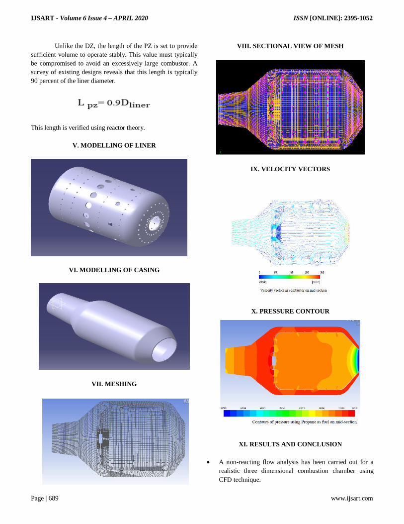
VIII. SECTIONAL VIEW OF MESH
IX. VELOCITY VECTORS
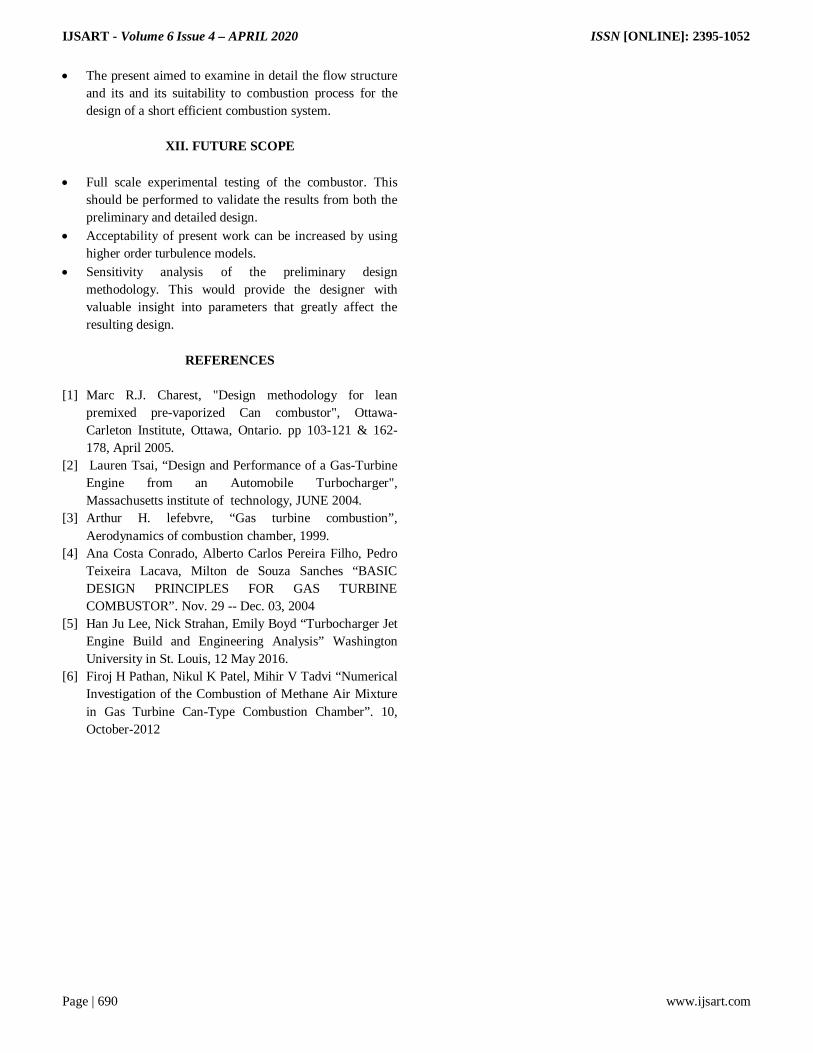
X. PRESSURE CONTOUR
XI. RESULTS AND CONCLUSION A non-reacting flow analysis has been carried out for a
realistic three dimensional combustion chamber using CFD technique.
IJSART - Volume 6 Issue 4 – APRIL 2020 ISSN [ONLINE]: 2395-1052
Page | 690 www.ijsart.com
The present aimed to examine in detail the flow structure and its and its suitability to combustion process for the design of a short efficient combustion system.
XII. FUTURE SCOPE
Full scale experimental testing of the combustor. This
should be performed to validate the results from both the preliminary and detailed design.
Acceptability of present work can be increased by using higher order turbulence models.
Sensitivity analysis of the preliminary design methodology. This would provide the designer with valuable insight into parameters that greatly affect the resulting design.
REFERENCES
[1] Marc R.J. Charest, "Design methodology for lean
premixed pre-vaporized Can combustor", Ottawa-Carleton Institute, Ottawa, Ontario. pp 103-121 & 162-178, April 2005.
[2] Lauren Tsai, “Design and Performance of a Gas-Turbine Engine from an Automobile Turbocharger", Massachusetts institute of technology, JUNE 2004.
[3] Arthur H. lefebvre, “Gas turbine combustion”, Aerodynamics of combustion chamber, 1999.
[4] Ana Costa Conrado, Alberto Carlos Pereira Filho, Pedro Teixeira Lacava, Milton de Souza Sanches “BASIC DESIGN PRINCIPLES FOR GAS TURBINE COMBUSTOR”. Nov. 29 -- Dec. 03, 2004
[5] Han Ju Lee, Nick Strahan, Emily Boyd “Turbocharger Jet Engine Build and Engineering Analysis” Washington University in St. Louis, 12 May 2016.
[6] Firoj H Pathan, Nikul K Patel, Mihir V Tadvi “Numerical Investigation of the Combustion of Methane Air Mixture in Gas Turbine Can-Type Combustion Chamber”. 10, October-2012