Embed Size (px)
Citation preview
This article was downloaded by: [University of Illinois at Urbana-Champaign]On: 20 May 2015, At: 02:30Publisher: Taylor & FrancisInforma Ltd Registered in England and Wales Registered Number: 1072954 Registeredoffice: Mortimer House, 37-41 Mortimer Street, London W1T 3JH, UK
Click for updates
Philosophical MagazinePublication details, including instructions for authors andsubscription information:http://www.tandfonline.com/loi/tphm20
Modelling of martensite slip andtwinning in NiTiHf shape memory alloysJ. Wanga & H. Sehitoglua
a Department of Mechanical Science and Engineering, Universityof Illinois at Urbana-Champaign, 1206 W. Green St., Urbana, IL61801, USAPublished online: 19 May 2014.
To cite this article: J. Wang & H. Sehitoglu (2014) Modelling of martensite slip andtwinning in NiTiHf shape memory alloys, Philosophical Magazine, 94:20, 2297-2317, DOI:10.1080/14786435.2014.913109
To link to this article: http://dx.doi.org/10.1080/14786435.2014.913109
PLEASE SCROLL DOWN FOR ARTICLE
Taylor & Francis makes every effort to ensure the accuracy of all the information (the“Content”) contained in the publications on our platform. However, Taylor & Francis,our agents, and our licensors make no representations or warranties whatsoever as tothe accuracy, completeness, or suitability for any purpose of the Content. Any opinionsand views expressed in this publication are the opinions and views of the authors,and are not the views of or endorsed by Taylor & Francis. The accuracy of the Contentshould not be relied upon and should be independently verified with primary sourcesof information. Taylor and Francis shall not be liable for any losses, actions, claims,proceedings, demands, costs, expenses, damages, and other liabilities whatsoever orhowsoever caused arising directly or indirectly in connection with, in relation to or arisingout of the use of the Content.
This article may be used for research, teaching, and private study purposes. Anysubstantial or systematic reproduction, redistribution, reselling, loan, sub-licensing,systematic supply, or distribution in any form to anyone is expressly forbidden. Terms &

Conditions of access and use can be found at http://www.tandfonline.com/page/terms-and-conditions
Dow
nloa
ded
by [
Uni
vers
ity o
f Il
linoi
s at
Urb
ana-
Cha
mpa
ign]
at 0
2:30
20
May
201
5
Modelling of martensite slip and twinning in NiTiHf shapememory alloys
J. Wang and H. Sehitoglu*
Department of Mechanical Science and Engineering, University of Illinois at Urbana-Champaign,1206 W. Green St., Urbana, IL 61801, USA
(Received 16 November 2013; accepted 31 March 2014)
High-temperature shape memory alloy NiTiHf holds considerable promise forstructural applications. An important consideration for these advanced alloysis the determination of the magnitude of the twinning stress. Theoretical stres-ses for twinning and dislocation slip in NiTiHf martensites are determined.The slip and twinning planes are (0 0 1) and (0 1 1) for monoclinic and ortho-rhombic crystals, respectively. The determination of the slip and twinningstress is achieved with a proposed Peierls–Nabarro-based formulationinformed with atomistic simulations. In the case of the twin, multiple disloca-tions comprising the twin nucleus are considered. The overall energy expres-sion is minimized to obtain the twinning and slip stresses. The magnitude ofthe predicted twinning stresses is lower than slip stresses which explains whythe NiTiHf alloys can undergo reversibility without plastic deformation. Infact, the predicted critical resolved shear stress levels of 433MPa for slip and236MPa for twinning in the case of 12.5% Hf agree very well with theexperimental measurements. The high slip resistance confirms that these mate-rials can be very attractive in load-bearing applications.
Keywords: shape memory materials; simulation; twinning; stresses; alloys;atomistic simulation
1. Introduction
Recently, there has been significant emphasis on high-temperature shape memory alloys[1–7] with potential industrial applications. The major impetus for these developmentsis that the use of NiTi above 100 °C is limited because of low slip resistance and irre-coverability [1,8]. We note that the martensitic transformation stress for NiTi increasesrapidly with increasing temperature, while the dislocation slip stress decreases graduallywith increasing temperature. For NiTi at temperatures above 100 °C, the lowering of theslip stress and other recovery mechanisms can induce plastic deformation. For the NiT-iHf alloys, the slip strength remains at a high level well beyond 100 °C [6]. One of themost promising among the high-temperature shape memory materials is NiTi with ter-nary Hf additions [4,9–11]. The widespread utilization of NiTiHf is limited primarilydue to the lack of understanding of their shape memory response. There is a correlationbetween composition and twin stress which needs to be established. The change incomposition also changes the lattice parameters and elastic constants, the transition from
*Corresponding author. Email: [email protected]
© 2014 Taylor & Francis
Philosophical Magazine, 2014Vol. 94, No. 20, 2297–2317, http://dx.doi.org/10.1080/14786435.2014.913109
Dow
nloa
ded
by [
Uni
vers
ity o
f Il
linoi
s at
Urb
ana-
Cha
mpa
ign]
at 0
2:30
20
May
201
5
B19′ to B19 martensites, and the planar fault energies that control the twinningresponse [12,13]. These alloys are either in the B19 (orthorhombic) or in the B19′(monoclinic) state depending on the Hf content. While research has substantially pro-gressed in the shape memory of NiTi, the understanding of the deformation by twinningis still in progress. Crystallographic planes for slip and twinning and atomic movementsfor simple lattices (such as fcc and bcc) have been established previously [14,15], butthe energetics of twinning in the orthorhombic and monoclinic crystals is rather com-plex and not well understood. The atomic positions present shuffles within the lattice.This paper addresses the determination of twinning stress and slip stress for NiTiHfalloys.
The deformation behaviour of monoclinic and orthorhombic martensites in NiTi-based shape memory alloys have been studied experimentally [16–20]. The results showthat the flow response of the binary NiTi is primarily due to twinning of the monocliniclattice at rather low stress levels (less than 20MPa). We note that the strength of NiTiagainst dislocation slip also depends on the microstructure, the heat-treatment and theprecipitate volume fraction [20–23]. It is well known that the addition of ternary ele-ments can also change the mechanical response of NiTi alloys [5,6,11,24]. The relativeroles of these hardening mechanisms require further research. The purpose of Hf addi-tions has been to raise the transformation temperatures opening potentially new applica-tions in aerospace industry [6]. As the hafnium content is increased to levels near 25%,the mechanical response such as the slip and twin stress levels should change substan-tially. The purpose of this paper is to determine the changes in slip stress and twinningstress via modelling without using empirical constants and the results are compared toexperiments for cases, where data are available. The methodology developed relies onthe generalized stacking fault energy (SFE) (GSFE) [14] for slip and the generalizedplanar fault energy (GPFE) [15] for twinning.
2. Simulation methods
We performed the first-principles total-energy calculations using the Vienna ab initioSimulations Package with the projector augmented wave method and the generalizedgradient approximation. In our simulations, Monkhorst–Pack 9 × 9 × 9 k-point mesheswere used for the Brillouin-zone integration. Ionic relaxation was applied by a conju-gate gradient algorithm and stopped when absolute values of internal forces were smal-ler than 5 × 10⁻³ eV/Å. The energy cut-off of 500 eV was used for the plane-wave basisset. The total energy was converged to less than 10−5 eV per atom. The energy barriersof dislocation slip and twinning in a crystal are characterized via the GSFE and GPFEcurves, respectively. GSFE is the interplanar potential energy determined by rigidly slid-ing one half of a crystal over the other half. It was first introduced by Vitek [14] and isa comprehensive definition of the fault energy associated with dislocation motion.GPFE provides a comprehensive description of twins, which is the energy per unit arearequired to form n-layer twins by shearing n consecutive layers along twinning direc-tion. We have used twelve (0 0 1) and (0 1 1) layers in the periodic supercell (no freesurfaces) to assess the converged energies in GSFE and GPFE curves. During the sheardeformation process, the volume and shape of the supercell were maintained constant,ensuring the correct monoclinic angle and twin/slip structure. In the present study, a fullatomic relaxation was carried out, during which atoms can move in the out of plane
2298 J. Wang and H. Sehitoglu
Dow
nloa
ded
by [
Uni
vers
ity o
f Il
linoi
s at
Urb
ana-
Cha
mpa
ign]
at 0
2:30
20
May
201
5
and normal to the slip and twin plane although these displacements are small relative tothe shear displacement. This relaxation process caused a small additional atomic dis-
placement r jrj ¼ffiffiffiffiffiffiffiffiffiffiffiffiffiffiffiffiffiffiffiffiffiffiffiffir2x þ r2y þ r2z
q� �deviating from the Burgers vector. Thus, the total
fault displacement is not exactly equal to shear displacement, u, but involves additionalr. The total energy of the deformed (faulted) crystal was minimized during this relaxa-tion process through which atoms can avoid coming too close to each other duringshear [25,26]. The calculations, involving the displacement in the parallel directions tothe twin and slip plane, provided more accurate energy barriers (GSFE and GPFE).
2.1. Prediction of critical twin nucleation stress by twin nucleation model
We proposed a twin nucleation model based on Peierls–Nabarro formulation to predictthe twinning stress in shape memory alloys (see more details in Ref. [27]). To predicttwinning stresses in NiTiHf alloys, we determined the total energy involved in the twinnucleation as follows:
Etotal ¼ Eint þ EGPFE þ Eline �W
¼ lb2
4pð1� mÞ ð1� m cos2 hÞXN�1
m¼1
lnLPmi¼1 di
þ lnLPmi¼2 di
þ � � � þ lnLPm
i¼N�1 di
� �
þXþ1
m¼�1cSF f ðmbÞ½ �bþ N � 1ð Þ
Xþ1
m¼�1ctwin f ðmbÞ½ �bþ Nlb2
2ð1� mÞ ð1� m cos2 hÞ
�XN�1
i¼1
sshdi; i ¼ 1; 2; 3; . . .;N � 1;
(1)
where, Eint is the twin dislocations interaction energy, EGPFE is the twin boundaryenergy (GPFE), Eline is the twin dislocations line energy and W is the applied work; μis the shear modulus in the twinning system, b is the twinning Burgers vector, m is thePoisson’s ratio, h is the angle between the Burgers vector and the dislocation line, L isthe dimensions of the crystal containing the twin; τ is the applied shear stress and theminimum τ to form a twin is called critical twin nucleation stress, τcrit; N is the numberof twin nucleation layers, h is the twin thickness, s is the twinning shear and di is theequilibrium spacing between two adjacent twinning dislocations i and i + 1 correspond-ing to the minimum total energy.
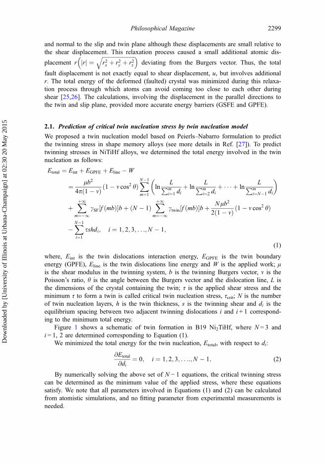
Figure 1 shows a schematic of twin formation in B19 Ni2TiHf, where N = 3 andi = 1, 2 are determined corresponding to Equation (1).
We minimized the total energy for the twin nucleation, Etotal, with respect to di:
@Etotal
@di¼ 0; i ¼ 1; 2; 3; . . .:;N � 1; (2)
By numerically solving the above set of N − 1 equations, the critical twinning stresscan be determined as the minimum value of the applied stress, where these equationssatisfy. We note that all parameters involved in Equations (1) and (2) can be calculatedfrom atomistic simulations, and no fitting parameter from experimental measurements isneeded.
Philosophical Magazine 2299
Dow
nloa
ded
by [
Uni
vers
ity o
f Il
linoi
s at
Urb
ana-
Cha
mpa
ign]
at 0
2:30
20
May
201
5
2.2. Prediction of Peierls stress for dislocation slip by extended P–N model
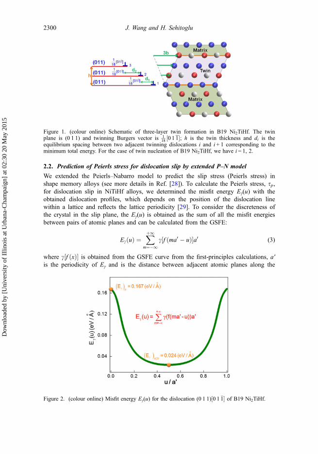
We extended the Peierls–Nabarro model to predict the slip stress (Peierls stress) inshape memory alloys (see more details in Ref. [28]). To calculate the Peierls stress, sp,for dislocation slip in NiTiHf alloys, we determined the misfit energy Eγ(u) with theobtained dislocation profiles, which depends on the position of the dislocation linewithin a lattice and reflects the lattice periodicity [29]. To consider the discreteness ofthe crystal in the slip plane, the Eγ(u) is obtained as the sum of all the misfit energiesbetween pairs of atomic planes and can be calculated from the GSFE:
EcðuÞ ¼Xþ1
m¼�1c f ðma0 � uÞ½ �a0 (3)
where c½f ðxÞ� is obtained from the GSFE curve from the first-principles calculations, a′is the periodicity of Eγ and is the distance between adjacent atomic planes along the
Figure 1. (colour online) Schematic of three-layer twin formation in B19 Ni2TiHf. The twinplane is (0 1 1) and twinning Burgers vector is 1
18 ½0 1 1�; h is the twin thickness and di is theequilibrium spacing between two adjacent twinning dislocations i and i + 1 corresponding to theminimum total energy. For the case of twin nucleation of B19 Ni2TiHf, we have i = 1, 2.
Figure 2. (colour online) Misfit energy Eγ(u) for the dislocation (0 1 1)½0 1 �1� of B19 Ni2TiHf.
2300 J. Wang and H. Sehitoglu
Dow
nloa
ded
by [
Uni
vers
ity o
f Il
linoi
s at
Urb
ana-
Cha
mpa
ign]
at 0
2:30
20
May
201
5
direction perpendicular to the dislocation line; f(x) is the dislocation profile (disregistryfunction) determined from the relative displacement of two half crystals in the slipplane along x direction [30], and u is the position of dislocation line.
Figure 2 shows the misfit energy Eγ(u) variation with the lattice period a′ for the(0 1 1)½0 1 �1� slip of B19 Ni2TiHf. The Peierls stress τp can be calculated by the maxi-
mum of 1bdEs
cðuÞdu . In the misfit energy curve, ðEs
cÞa0=2 is the minimum value of EscðuÞ and
provides an estimate of the core energy of dislocations; ðEscÞp, defined as the Peierls
energy, is the barrier required to move dislocations.
3. Results
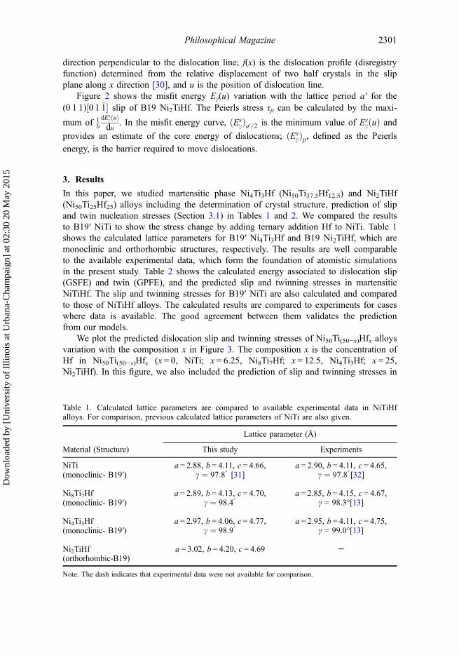
In this paper, we studied martensitic phase Ni4Ti3Hf (Ni50Ti37.5Hf12.5) and Ni2TiHf(Ni50Ti25Hf25) alloys including the determination of crystal structure, prediction of slipand twin nucleation stresses (Section 3.1) in Tables 1 and 2. We compared the resultsto B19′ NiTi to show the stress change by adding ternary addition Hf to NiTi. Table 1shows the calculated lattice parameters for B19′ Ni4Ti3Hf and B19 Ni2TiHf, which aremonoclinic and orthorhombic structures, respectively. The results are well comparableto the available experimental data, which form the foundation of atomistic simulationsin the present study. Table 2 shows the calculated energy associated to dislocation slip(GSFE) and twin (GPFE), and the predicted slip and twinning stresses in martensiticNiTiHf. The slip and twinning stresses for B19′ NiTi are also calculated and comparedto those of NiTiHf alloys. The calculated results are compared to experiments for caseswhere data is available. The good agreement between them validates the predictionfrom our models.
We plot the predicted dislocation slip and twinning stresses of Ni50Ti(50−x)Hfx alloysvariation with the composition x in Figure 3. The composition x is the concentration ofHf in Ni50Ti(50−x)Hfx (x = 0, NiTi; x = 6.25, Ni8Ti7Hf; x = 12.5, Ni4Ti3Hf; x = 25,Ni2TiHf). In this figure, we also included the prediction of slip and twinning stresses in
Table 1. Calculated lattice parameters are compared to available experimental data in NiTiHfalloys. For comparison, previous calculated lattice parameters of NiTi are also given.
Material (Structure)
Lattice parameter (Å)
This study Experiments
NiTi a = 2.88, b = 4.11, c = 4.66,c ¼ 97:8
�[31]
a = 2.90, b = 4.11, c = 4.65,c ¼ 97:8
�[32](monoclinic- B19′)
Ni8Ti7Hf a = 2.89, b = 4.13, c = 4.70,c ¼ 98:4
�a = 2.85, b = 4.15, c = 4.67,
γ = 98.3°[13](monoclinic- B19′)
Ni4Ti3Hf a = 2.97, b = 4.06, c = 4.77,c ¼ 98:9
�a = 2.95, b = 4.11, c = 4.75,
γ = 99.0°[13](monoclinic- B19′)
Ni2TiHf a = 3.02, b = 4.20, c = 4.69 -(orthorhombic-B19)
Note: The dash indicates that experimental data were not available for comparison.
Philosophical Magazine 2301
Dow
nloa
ded
by [
Uni
vers
ity o
f Il
linoi
s at
Urb
ana-
Cha
mpa
ign]
at 0
2:30
20
May
201
5
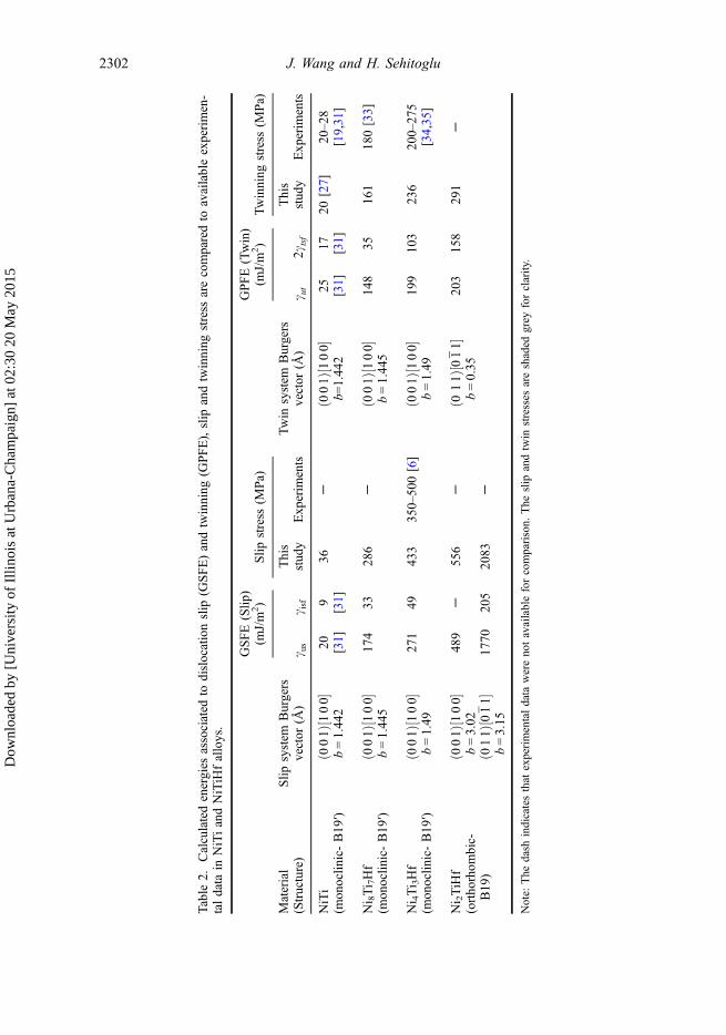
Table2.
Calculatedenergies
associated
todislocationslip
(GSFE)andtwinning
(GPFE),slip
andtwinning
stress
arecomparedto
availableexperimen-
taldata
inNiTiandNiTiHfalloys.
Material
(Structure)
Slip
system
Burgers
vector
(Å)
GSFE(Slip
)(m
J/m
2)
Slip
stress
(MPa)
Twin
system
Burgers
vector
(Å)
GPFE(Twin)
(mJ/m
2)
Twinning
stress
(MPa)
c us
c isf
This
stud
yExp
erim
ents
c ut
2ctsf
This
stud
yExp
erim
ents
NiTi
ð001Þ½100�
20 [31]
9[31]
36-
ð001Þ½100�
25 [31]
17 [31]
20[27]
20–28
[19,31]
(mon
oclin
ic-B19
′)b=1.44
2b=
1.44
2
Ni 8Ti 7Hf
ð001Þ½100�
174
3328
6-
ð001Þ½100�
148
3516
118
0[33]
(mon
oclin
ic-B19
′)b=1.44
5b=1.44
5
Ni 4Ti 3Hf
ð001Þ½100�
271
4943
335
0–50
0[6]
ð001Þ½100�
199
103
236
200–27
5[34,35]
(mon
oclin
ic-B19
′)b=1.49
b=1.49
Ni 2TiHf
ð001Þ½100�
489
-55
6-
ð011Þ½011�
203
158
291
-(ortho
rhom
bic-
B19
)b=3.02
b=0.35
ð011Þ½011�
1770
205
2083
-b=3.15
Note:
The
dash
indicatesthat
experimentaldata
werenotavailableforcomparison.
The
slip
andtwin
stresses
areshaded
grey
forclarity.
2302 J. Wang and H. Sehitoglu
Dow
nloa
ded
by [
Uni
vers
ity o
f Il
linoi
s at
Urb
ana-
Cha
mpa
ign]
at 0
2:30
20
May
201
5
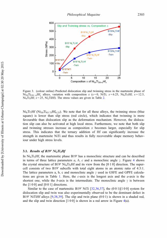
Ni8Ti7Hf (Ni50Ti43.75Hf6.25). We note that for all these alloys, the twinning stress (bluesquare) is lower than slip stress (red circle), which indicates that twinning is morefavourable than dislocation slip as the deformation mechanism. However, the disloca-tion slip can also be activated at high local stress. Furthermore, we note that both slipand twinning stresses increase as composition x becomes larger, especially for slipstress. This indicates that the ternary addition of Hf can significantly increase thestrength in martensite NiTi and thus results in fully recoverable shape memory behav-iour under high stress levels.
3.1. Results of B19′ Ni4Ti3Hf
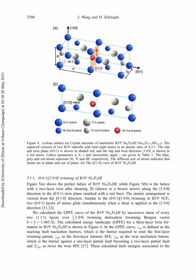
In Ni4Ti3Hf, the martensitic phase B19′ has a monoclinic structure and can be describedin terms of three lattice parameters a, b, c and a monoclinic angle c. Figure 4 showsthe crystal structure of B19′ Ni4Ti3Hf and its view from the [0 1 0] direction. The super-cell consists of two B19′ subcells with total eight atoms in an atomic ratio of 4:3:1.The lattice parameters a, b, c and monoclinic angle c used in GSFE and GPFE calcula-tions are given in Table 1. Here, the c-axis is the longest axis and the a-axis is theshortest one, while the b-axis is the intermediate. The monoclinic angle c is betweenthe [1 0 0] and [0 0 1] directions.
Similar to the case of martensitic B19′ NiTi [32,36,37], the (0 0 1)[1 0 0] system fordislocation slip and twin was also experimentally observed to be the dominant defect inB19′ NiTiHf alloys [9,38,39]. The slip and twin plane (0 0 1) is shown in a shaded red,and the slip and twin direction [1 0 0] is shown in a red arrow in Figure 4(a).
Figure 3. (colour online) Predicted dislocation slip and twinning stress in the martensite phase ofNi50Ti(50−x)Hfx alloys, variation with composition x (x = 0, NiTi; x = 6.25, Ni8Ti7Hf; x = 12.5,Ni4Ti3Hf; x = 25, Ni2TiHf). The stress values are given in Table 2.
Philosophical Magazine 2303
Dow
nloa
ded
by [
Uni
vers
ity o
f Il
linoi
s at
Urb
ana-
Cha
mpa
ign]
at 0
2:30
20
May
201
5
3.1.1. (0 0 1)[1 0 0] twinning of B19′ Ni4Ti3Hf
Figure 5(a) shows the perfect lattice of B19′ Ni4Ti3Hf, while Figure 5(b) is the latticewith a two-layer twin after shearing 2b (shown in a brown arrow) along the [1 0 0]direction in the (0 0 1) twin plane (marked with a red line). The atomic arrangement isviewed from the [0 1 0] direction. Similar to the (0 0 1)[1 0 0] twinning in B19′ NiTi,two (0 0 1) layers of atoms glide simultaneously when a shear is applied in the [1 0 0]direction [31,32].
We calculated the GPFE curve of the B19′ Ni4Ti3Hf by successive shear of everytwo (1 1 1) layers over 1
2 1 0 0½ � twinning dislocation (twinning Burgers vectorb ¼ a
2 ¼ 1:485 A). The calculated energy landscape (GPFE) for a three-layer twin for-mation in B19′ Ni4Ti3Hf is shown in Figure 6. In the GPFE curve, cus is defined as thestacking fault nucleation barriers, which is the barrier required to emit the first-layertwinning partial, cisf as the first-layer intrinsic SFE, cuf as the twin nucleation barrier,which is the barrier against a one-layer partial fault becoming a two-layer partial faultand 2ctsf as twice the twin SFE [27]. These calculated fault energies associated to the
Figure 4. (colour online) (a) Crystal structure of martensite B19′ Ni4Ti3Hf (Ni50Ti37.5Hf12.5). Thesupercell consists of two B19′ subcells with total eight atoms in an atomic ratio of 4:3:1. The slipand twin plane (0 0 1) is shown in shaded red, and the slip and twin direction ½1 0 0� is shown ina red arrow. Lattice parameters a, b, c and monoclinic angle c are given in Table 1. The blue,grey and red atoms represent Ni, Ti and Hf, respectively. The different size of atoms indicates thatatoms are in plane and out of plane. (b) The [0 1 0] view of B19′ Ni4Ti3Hf.
2304 J. Wang and H. Sehitoglu
Dow
nloa
ded
by [
Uni
vers
ity o
f Il
linoi
s at
Urb
ana-
Cha
mpa
ign]
at 0
2:30
20
May
201
5
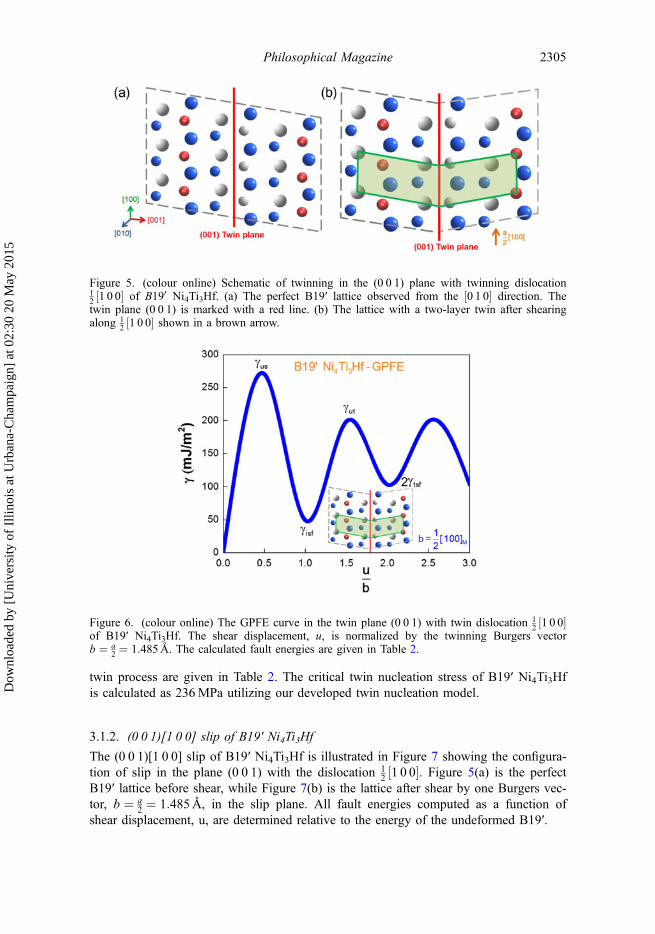
twin process are given in Table 2. The critical twin nucleation stress of B19′ Ni4Ti3Hfis calculated as 236MPa utilizing our developed twin nucleation model.
3.1.2. (0 0 1)[1 0 0] slip of B19′ Ni4Ti3Hf
The (0 0 1)[1 0 0] slip of B19′ Ni4Ti3Hf is illustrated in Figure 7 showing the configura-tion of slip in the plane (0 0 1) with the dislocation 1
2 ½1 0 0�. Figure 5(a) is the perfectB19′ lattice before shear, while Figure 7(b) is the lattice after shear by one Burgers vec-tor, b ¼ a
2 ¼ 1:485 A, in the slip plane. All fault energies computed as a function ofshear displacement, u, are determined relative to the energy of the undeformed B19′.
Figure 5. (colour online) Schematic of twinning in the (0 0 1) plane with twinning dislocation12 ½1 0 0� of B190 Ni4Ti3Hf. (a) The perfect B19′ lattice observed from the ½0 1 0� direction. Thetwin plane (0 0 1) is marked with a red line. (b) The lattice with a two-layer twin after shearingalong 1
2 ½1 0 0� shown in a brown arrow.
Figure 6. (colour online) The GPFE curve in the twin plane (0 0 1) with twin dislocation 12 ½1 0 0�
of B19′ Ni4Ti3Hf. The shear displacement, u, is normalized by the twinning Burgers vectorb ¼ a
2 ¼ 1:485 A. The calculated fault energies are given in Table 2.
Philosophical Magazine 2305
Dow
nloa
ded
by [
Uni
vers
ity o
f Il
linoi
s at
Urb
ana-
Cha
mpa
ign]
at 0
2:30
20
May
201
5
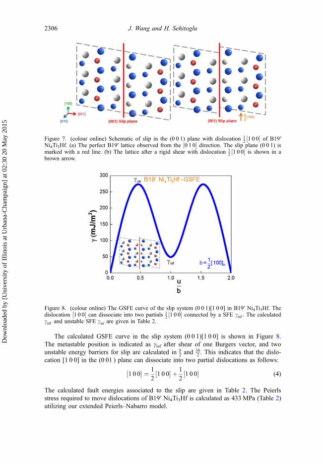
The calculated GSFE curve in the slip system (0 0 1)[1 0 0] is shown in Figure 8.The metastable position is indicated as γisf after shear of one Burgers vector, and twounstable energy barriers for slip are calculated in b
2 and3b2 . This indicates that the dislo-
cation [1 0 0] in the (0 01 ) plane can dissociate into two partial dislocations as follows:
1 0 0½ � ¼ 1
21 0 0½ � þ 1
21 0 0½ � (4)
The calculated fault energies associated to the slip are given in Table 2. The Peierlsstress required to move dislocations of B19′ Ni4Ti3Hf is calculated as 433MPa (Table 2)utilizing our extended Peierls–Nabarro model.
Figure 7. (colour online) Schematic of slip in the (0 0 1) plane with dislocation 12 ½1 0 0� of B19′
Ni4Ti3Hf. (a) The perfect B19′ lattice observed from the ½0 1 0� direction. The slip plane (0 0 1) ismarked with a red line. (b) The lattice after a rigid shear with dislocation 1
2 ½1 0 0� is shown in abrown arrow.
Figure 8. (colour online) The GSFE curve of the slip system (0 0 1)[1 0 0] in B19′ Ni4Ti3Hf. Thedislocation ½1 0 0� can dissociate into two partials 1
2 ½1 0 0� connected by a SFE cisf . The calculatedcisf and unstable SFE cus are given in Table 2.
2306 J. Wang and H. Sehitoglu
Dow
nloa
ded
by [
Uni
vers
ity o
f Il
linoi
s at
Urb
ana-
Cha
mpa
ign]
at 0
2:30
20
May
201
5
3.2. Results of B19 Ni2TiHf
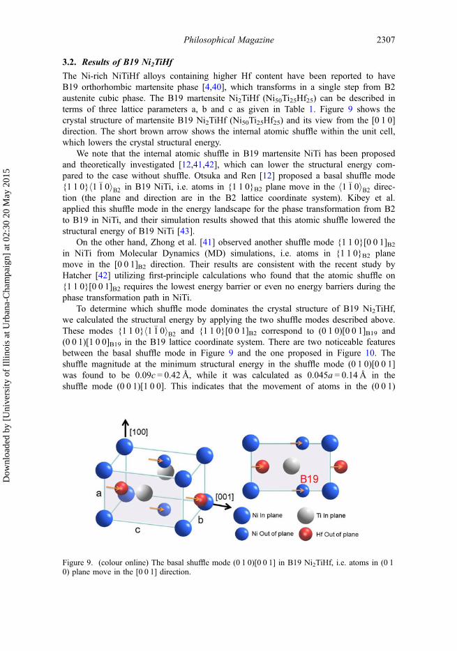
The Ni-rich NiTiHf alloys containing higher Hf content have been reported to haveB19 orthorhombic martensite phase [4,40], which transforms in a single step from B2austenite cubic phase. The B19 martensite Ni2TiHf (Ni50Ti25Hf25) can be described interms of three lattice parameters a, b and c as given in Table 1. Figure 9 shows thecrystal structure of martensite B19 Ni2TiHf (Ni50Ti25Hf25) and its view from the [0 1 0]direction. The short brown arrow shows the internal atomic shuffle within the unit cell,which lowers the crystal structural energy.
We note that the internal atomic shuffle in B19 martensite NiTi has been proposedand theoretically investigated [12,41,42], which can lower the structural energy com-pared to the case without shuffle. Otsuka and Ren [12] proposed a basal shuffle mode{1 1 0}h1 �1 0iB2 in B19 NiTi, i.e. atoms in {1 1 0}B2 plane move in the h1 �1 0iB2 direc-tion (the plane and direction are in the B2 lattice coordinate system). Kibey et al.applied this shuffle mode in the energy landscape for the phase transformation from B2to B19 in NiTi, and their simulation results showed that this atomic shuffle lowered thestructural energy of B19 NiTi [43].
On the other hand, Zhong et al. [41] observed another shuffle mode {1 1 0}[0 0 1]B2in NiTi from Molecular Dynamics (MD) simulations, i.e. atoms in {1 1 0}B2 planemove in the [0 0 1]B2 direction. Their results are consistent with the recent study byHatcher [42] utilizing first-principle calculations who found that the atomic shuffle on{1 1 0}[0 0 1]B2 requires the lowest energy barrier or even no energy barriers during thephase transformation path in NiTi.
To determine which shuffle mode dominates the crystal structure of B19 Ni2TiHf,we calculated the structural energy by applying the two shuffle modes described above.These modes {1 1 0}h1 �1 0iB2 and {1 1 0}[0 0 1]B2 correspond to (0 1 0)[0 0 1]B19 and(0 0 1)[1 0 0]B19 in the B19 lattice coordinate system. There are two noticeable featuresbetween the basal shuffle mode in Figure 9 and the one proposed in Figure 10. Theshuffle magnitude at the minimum structural energy in the shuffle mode (0 1 0)[0 0 1]was found to be 0.09c = 0.42 Å, while it was calculated as 0.045a = 0.14 Å in theshuffle mode (0 0 1)[1 0 0]. This indicates that the movement of atoms in the (0 0 1)
Figure 9. (colour online) The basal shuffle mode (0 1 0)[0 0 1] in B19 Ni2TiHf, i.e. atoms in (0 10) plane move in the [0 0 1] direction.
Philosophical Magazine 2307
Dow
nloa
ded
by [
Uni
vers
ity o
f Il
linoi
s at
Urb
ana-
Cha
mpa
ign]
at 0
2:30
20
May
201
5
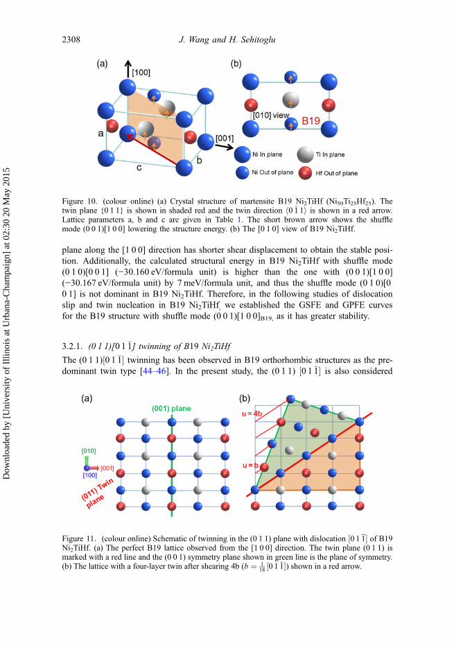
plane along the [1 0 0] direction has shorter shear displacement to obtain the stable posi-tion. Additionally, the calculated structural energy in B19 Ni2TiHf with shuffle mode(0 1 0)[0 0 1] (−30.160 eV/formula unit) is higher than the one with (0 0 1)[1 0 0](−30.167 eV/formula unit) by 7 meV/formula unit, and thus the shuffle mode (0 1 0)[00 1] is not dominant in B19 Ni2TiHf. Therefore, in the following studies of dislocationslip and twin nucleation in B19 Ni2TiHf, we established the GSFE and GPFE curvesfor the B19 structure with shuffle mode (0 0 1)[1 0 0]B19, as it has greater stability.
3.2.1. (0 1 1)[0 1 �1] twinning of B19 Ni2TiHf
The (0 1 1)½0 1 �1� twinning has been observed in B19 orthorhombic structures as the pre-dominant twin type [44–46]. In the present study, the (0 1 1) ½0 1 �1� is also considered
Figure 10. (colour online) (a) Crystal structure of martensite B19 Ni2TiHf (Ni50Ti25Hf25). Thetwin plane {0 1 1} is shown in shaded red and the twin direction h0 �1 1i is shown in a red arrow.Lattice parameters a, b and c are given in Table 1. The short brown arrow shows the shufflemode (0 0 1)[1 0 0] lowering the structure energy. (b) The [0 1 0] view of B19 Ni2TiHf.
Figure 11. (colour online) Schematic of twinning in the (0 1 1) plane with dislocation ½0 1 1� of B19Ni2TiHf. (a) The perfect B19 lattice observed from the [1 0 0] direction. The twin plane (0 1 1) ismarked with a red line and the (0 0 1) symmetry plane shown in green line is the plane of symmetry.(b) The lattice with a four-layer twin after shearing 4b (b ¼ 1
18 ½0 1 �1�) shown in a red arrow.
2308 J. Wang and H. Sehitoglu
Dow
nloa
ded
by [
Uni
vers
ity o
f Il
linoi
s at
Urb
ana-
Cha
mpa
ign]
at 0
2:30
20
May
201
5
as the twinning system in B19 Ni2TiHf. Figure 11(a) shows the perfect lattice of B19Ni2TiHf, while Figure 11(b) is the lattice with a four-layer twin after shearing 4b(shown in a red arrow) along the ½0 1 �1� direction in the (0 1 1) plane (twin plane ismarked with a red line). The atomic arrangement is viewed from the [1 0 0] direction.We note that unlike B19′ monoclinic structure, where (0 0 1) plane is a twin plane, the(0 0 1) plane in B19 orthorhombic structure is a plane of symmetry and therefore is nota twin plane [44]. Figure 11(a) shows the (0 0 1) plane (marked in green line) as a planeof symmetry, which will not provide twinning in the orthorhombic unit cell.
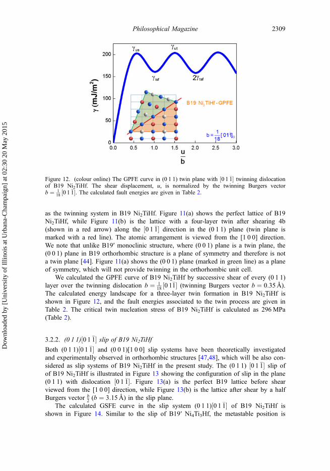
We calculated the GPFE curve of B19 Ni2TiHf by successive shear of every (0 1 1)layer over the twinning dislocation b ¼ 1
18 ½0 1�1� (twinning Burgers vector b ¼ 0:35 A).The calculated energy landscape for a three-layer twin formation in B19 Ni2TiHf isshown in Figure 12, and the fault energies associated to the twin process are given inTable 2. The critical twin nucleation stress of B19 Ni2TiHf is calculated as 296MPa(Table 2).
3.2.2. (0 1 1)½0 1 �1� slip of B19 Ni2TiHf
Both (0 1 1)½0 1 �1� and (0 0 1)[1 0 0] slip systems have been theoretically investigatedand experimentally observed in orthorhombic structures [47,48], which will be also con-sidered as slip systems of B19 Ni2TiHf in the present study. The (0 1 1) ½0 1 �1� slip ofof B19 Ni2TiHf is illustrated in Figure 13 showing the configuration of slip in the plane(0 1 1) with dislocation ½0 1 �1�. Figure 13(a) is the perfect B19 lattice before shearviewed from the [1 0 0] direction, while Figure 13(b) is the lattice after shear by a halfBurgers vector b
2 (b ¼ 3:15 A) in the slip plane.The calculated GSFE curve in the slip system (0 1 1)½0 1 �1� of B19 Ni2TiHf is
shown in Figure 14. Similar to the slip of B19′ Ni4Ti3Hf, the metastable position is
Figure 12. (colour online) The GPFE curve in (0 1 1) twin plane with ½0 1 �1� twinning dislocationof B19 Ni2TiHf. The shear displacement, u, is normalized by the twinning Burgers vectorb ¼ 1
18 ½0 1 �1�. The calculated fault energies are given in Table 2.
Philosophical Magazine 2309
Dow
nloa
ded
by [
Uni
vers
ity o
f Il
linoi
s at
Urb
ana-
Cha
mpa
ign]
at 0
2:30
20
May
201
5
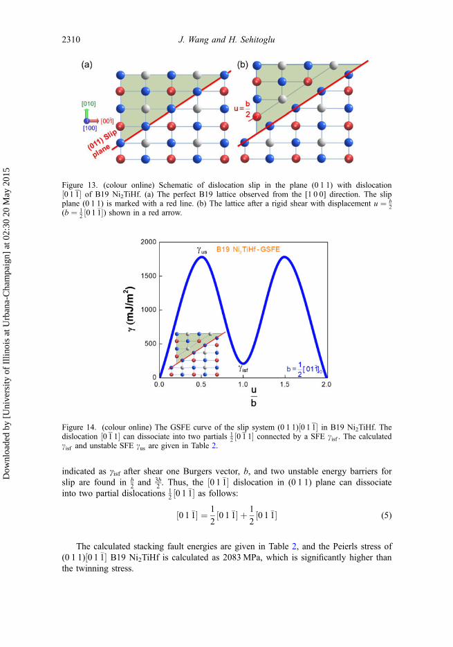
indicated as γisf after shear one Burgers vector, b, and two unstable energy barriers forslip are found in b
2 and 3b2 . Thus, the ½0 1 �1� dislocation in (0 1 1) plane can dissociate
into two partial dislocations 12 ½0 1 �1� as follows:
0 1 �1½ � ¼ 1
20 1 �1½ � þ 1
20 1 �1½ � (5)
The calculated stacking fault energies are given in Table 2, and the Peierls stress of(0 1 1)½0 1 �1� B19 Ni2TiHf is calculated as 2083MPa, which is significantly higher thanthe twinning stress.
Figure 13. (colour online) Schematic of dislocation slip in the plane (0 1 1) with dislocation½0 1 1� of B19 Ni2TiHf. (a) The perfect B19 lattice observed from the [1 0 0] direction. The slipplane (0 1 1) is marked with a red line. (b) The lattice after a rigid shear with displacement u ¼ b
2(b ¼ 1
2 ½0 1 �1�) shown in a red arrow.
Figure 14. (colour online) The GSFE curve of the slip system (0 1 1)½0 1 1� in B19 Ni2TiHf. Thedislocation ½0 1 1� can dissociate into two partials 1
2 ½0 1 1� connected by a SFE cisf . The calculatedcisf and unstable SFE cus are given in Table 2.
2310 J. Wang and H. Sehitoglu
Dow
nloa
ded
by [
Uni
vers
ity o
f Il
linoi
s at
Urb
ana-
Cha
mpa
ign]
at 0
2:30
20
May
201
5
3.2.3. (0 0 1)[1 0 0] slip of B19 Ni2TiHf
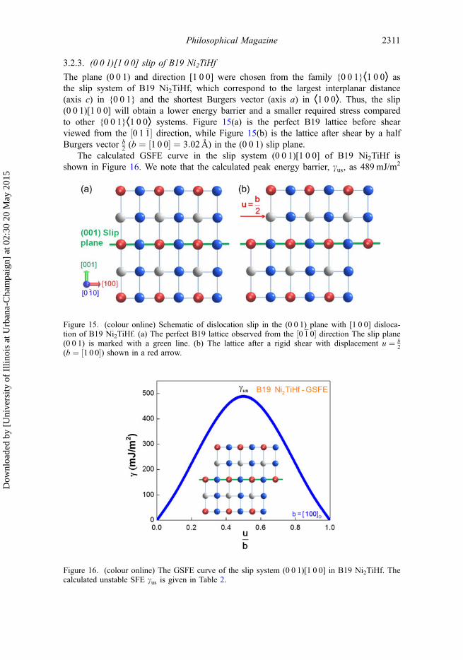
The plane (0 0 1) and direction [1 0 0] were chosen from the family {0 0 1}⟨1 0 0⟩ asthe slip system of B19 Ni2TiHf, which correspond to the largest interplanar distance(axis c) in {0 0 1} and the shortest Burgers vector (axis a) in ⟨1 0 0⟩. Thus, the slip(0 0 1)[1 0 0] will obtain a lower energy barrier and a smaller required stress comparedto other {0 0 1}⟨1 0 0⟩ systems. Figure 15(a) is the perfect B19 lattice before shearviewed from the ½0 1 �1� direction, while Figure 15(b) is the lattice after shear by a halfBurgers vector b
2 (b ¼ ½1 0 0� ¼ 3:02 A) in the (0 0 1) slip plane.The calculated GSFE curve in the slip system (0 0 1)[1 0 0] of B19 Ni2TiHf is
shown in Figure 16. We note that the calculated peak energy barrier, cus, as 489 mJ/m2
Figure 15. (colour online) Schematic of dislocation slip in the (0 0 1) plane with [1 0 0] disloca-tion of B19 Ni2TiHf. (a) The perfect B19 lattice observed from the ½0 1 0� direction The slip plane(0 0 1) is marked with a green line. (b) The lattice after a rigid shear with displacement u ¼ b
2(b ¼ ½1 0 0�) shown in a red arrow.
Figure 16. (colour online) The GSFE curve of the slip system (0 0 1)[1 0 0] in B19 Ni2TiHf. Thecalculated unstable SFE cus is given in Table 2.
Philosophical Magazine 2311
Dow
nloa
ded
by [
Uni
vers
ity o
f Il
linoi
s at
Urb
ana-
Cha
mpa
ign]
at 0
2:30
20
May
201
5
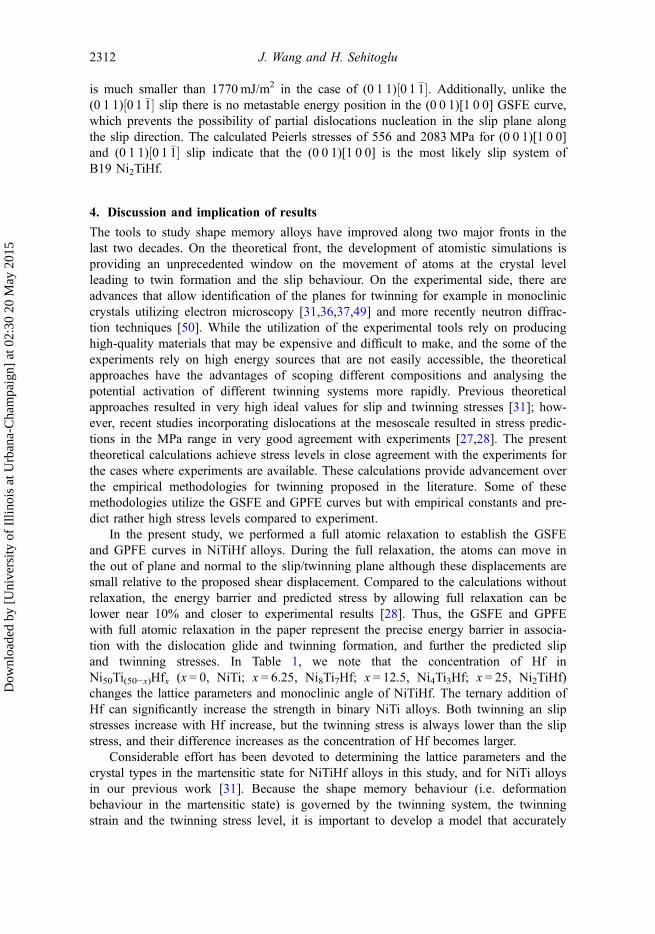
is much smaller than 1770 mJ/m2 in the case of (0 1 1)½0 1 �1�. Additionally, unlike the(0 1 1)½0 1 �1� slip there is no metastable energy position in the (0 0 1)[1 0 0] GSFE curve,which prevents the possibility of partial dislocations nucleation in the slip plane alongthe slip direction. The calculated Peierls stresses of 556 and 2083MPa for (0 0 1)[1 0 0]and (0 1 1)½0 1 �1� slip indicate that the (0 0 1)[1 0 0] is the most likely slip system ofB19 Ni2TiHf.
4. Discussion and implication of results
The tools to study shape memory alloys have improved along two major fronts in thelast two decades. On the theoretical front, the development of atomistic simulations isproviding an unprecedented window on the movement of atoms at the crystal levelleading to twin formation and the slip behaviour. On the experimental side, there areadvances that allow identification of the planes for twinning for example in monocliniccrystals utilizing electron microscopy [31,36,37,49] and more recently neutron diffrac-tion techniques [50]. While the utilization of the experimental tools rely on producinghigh-quality materials that may be expensive and difficult to make, and the some of theexperiments rely on high energy sources that are not easily accessible, the theoreticalapproaches have the advantages of scoping different compositions and analysing thepotential activation of different twinning systems more rapidly. Previous theoreticalapproaches resulted in very high ideal values for slip and twinning stresses [31]; how-ever, recent studies incorporating dislocations at the mesoscale resulted in stress predic-tions in the MPa range in very good agreement with experiments [27,28]. The presenttheoretical calculations achieve stress levels in close agreement with the experiments forthe cases where experiments are available. These calculations provide advancement overthe empirical methodologies for twinning proposed in the literature. Some of thesemethodologies utilize the GSFE and GPFE curves but with empirical constants and pre-dict rather high stress levels compared to experiment.
In the present study, we performed a full atomic relaxation to establish the GSFEand GPFE curves in NiTiHf alloys. During the full relaxation, the atoms can move inthe out of plane and normal to the slip/twinning plane although these displacements aresmall relative to the proposed shear displacement. Compared to the calculations withoutrelaxation, the energy barrier and predicted stress by allowing full relaxation can belower near 10% and closer to experimental results [28]. Thus, the GSFE and GPFEwith full atomic relaxation in the paper represent the precise energy barrier in associa-tion with the dislocation glide and twinning formation, and further the predicted slipand twinning stresses. In Table 1, we note that the concentration of Hf inNi50Ti(50−x)Hfx (x = 0, NiTi; x = 6.25, Ni8Ti7Hf; x = 12.5, Ni4Ti3Hf; x = 25, Ni2TiHf)changes the lattice parameters and monoclinic angle of NiTiHf. The ternary addition ofHf can significantly increase the strength in binary NiTi alloys. Both twinning an slipstresses increase with Hf increase, but the twinning stress is always lower than the slipstress, and their difference increases as the concentration of Hf becomes larger.
Considerable effort has been devoted to determining the lattice parameters and thecrystal types in the martensitic state for NiTiHf alloys in this study, and for NiTi alloysin our previous work [31]. Because the shape memory behaviour (i.e. deformationbehaviour in the martensitic state) is governed by the twinning system, the twinningstrain and the twinning stress level, it is important to develop a model that accurately
2312 J. Wang and H. Sehitoglu
Dow
nloa
ded
by [
Uni
vers
ity o
f Il
linoi
s at
Urb
ana-
Cha
mpa
ign]
at 0
2:30
20
May
201
5
predicts the twinning stress. One of the most important twinning planes in NiTi B19′ isthe (1 0 0) type. At much higher strains, higher twin modes can be activated as shownin earlier studies [31,37]. But these occur at higher stresses and result in partially recov-erable strains. For the B19 crystal structure which occurs when the ternary elementsexceed approximately 20%, the (0 1 1) plane displays the twinning mirror symmetry,while the (0 0 1) has not been observed in experiments [44]. Therefore, the (0 0 1) and(0 1 1) crystal planes were studied for B19′ and B19, respectively. We note that becausethe crystal planes differ, the Burgers vectors associated with B19′ and B19 differ con-siderably as noted in Tables 1 and 2. We note that there are two internal atomic shufflemodes, (0 1 0)[0 0 1] and (0 0 1)[1 0 0], proposed in the B19 orthorhombic NiTi [12,41],and they can lower the structural energy from the first-principles and MD simulations[41,42]. We applied both these shuffle modes within the B19 Ni2TiHf in our firstprinciple calculations, and found the structural energy involving the shuffle mode(0 0 1)[1 0 0] is lower than the one with the mode (0 1 0)[0 0 1]. Therefore, the shufflemode (0 0 1)[1 0 0] dominates in the crystal structure of B19 Ni2TiHf and we estab-lished the GSFE and GPFE curves for the structure with this mode as it has greater sta-bility. Additionally, we note that the calculated shuffle magnitude of NiTiHf is 0.42 and0.14 Å in the shuffle modes (0 1 0)[0 0 1] and (0 0 1)[1 0 0], respectively. These valuesare different from the corresponding shuffles of 0.46 Å [43] and 0.17 Å [51] for (0 1 0)[0 0 1] and (0 0 1)[1 0 0], respectively, reported for NiTi.
For a crystal structure undergoing plastic deformation, at least five independent slip(or twinning, which forms another plastic deformation mode) systems are needed toaccommodate arbitrary deformations [52,53]. We note that for the plastic deformationof B19′ Ni4Ti3Hf, there is only one independent slip (twinning) system (0 0 1)[1 0 0] forthe family {0 0 1}⟨1 0 0⟩, since in the low-symmetry monoclinic structure the (0 0 1)plane is different to (1 0 0) and (0 1 0) planes and [1 0 0] direction is different to [0 1 0]and [0 0 1] directions. Therefore, additional independent slip (twinning) systems arerequired and can be activated at higher applied stresses, such as (1 0 0)[0 0 1],ð2 0 �1Þ½�1 0 �2�, ð2 0 1Þ½1 0 �2� and ð�1 �1 3Þ twin, which are also experimentally observed inB19′ NiTi [54]. For the plastic deformation of B19 Ni2TiHf, we studied two indepen-dent slip (twinning) systems (0 0 1)[1 0 0] and (0 1 1)½0 1 �1�, but ⟨1 1 2⟩ twinning [55,56]can be activated at higher stress level to form additional deformation systems.
The design of shape memory alloys requires that the twinning stress remains belowthe slip stress [27,57]. There is ample demonstration of dislocation generation in shapememory alloys that curtail the reversibility of transformation, produce poor fatigue andshape memory performance [6,23,58–60]. Any attempts to produce alloys that raise theslip resistance without markedly reducing the transformation strain magnitudes areexpected to be adopted in structural applications. The NiTi in binary compositions pro-duce large strains and excellent reversibility, and with suitable texturing and ageingtreatments can possess higher slip resistance [19,61–63]. The addition of ternary ele-ments give additional freedom in elevating the strength levels. Several ternary additionsin NiTi such as Pd, Pt, Cu and Fe have been extensively studied [4,10,42,64–67].Through the Peierls–Nabarro formulation, we note that the lattice parameters of crystalstructure characterize the materials critical stress in slip and twinning. Shearing with alarger Burgers vector requires higher critical stresses [27,68]. For materials having thesame slip and twinning systems, the Burgers vector is governed by the lattice parameter.The available experimental data show that the lattice parameter forming the Burgers
Philosophical Magazine 2313
Dow
nloa
ded
by [
Uni
vers
ity o
f Il
linoi
s at
Urb
ana-
Cha
mpa
ign]
at 0
2:30
20
May
201
5
vector in B19′ NiTiPd and B19′ NiTiFe are 2.79 and 2.87 Å, respectively [67]. Thesevalues are much smaller than the lattice parameter of 2.97 Å in B19′ NiTiHf. Addition-ally, we note that among these ternary elements, Hf has the largest atomic radius of1.55 Å compared to those of Pt (1.35 Å), Pd (1.40 Å), Cu (1.35 Å) and Fe (1.40 Å)[69]. The large atomic radius of Hf results in increase in the Ni–Ni and Ti–Ti bondlengths in the martensite lattice, which is manifested by a higher maximum fault energyand thus higher slip and twinning stresses. Furthermore, ageing the nickel richNi50.3Ti29.7Hf20 produces a precipitate phase [70] that will increase the slip resistance[71]. However, in the present calculations, we consider stoichiometric compositions andsolutionized states. In summary, controlling the plastic deformation and facilitatingtwinning represents a key in design of advanced shape memory alloys.
5. Conclusions
The work supports the following conclusions:
(1) The fault energies characterizing slip and twinning are elevated with additionsof hafnium to NiTi alloy. The corresponding twin and slip stresses are calcu-lated and it is shown that NiTiHf martensites undergo twinning at lower stresslevels compared to the slip stresses. Both slip and twinning stresses for martens-ite NiTiHf increase as the Hf content becomes larger. Compared to the slipstress of 36MPa in martensitic NiTi, the slip stress in martensite NiTiHf variesfrom 286 to 556MPa. The twinning stress in martensite NiTiHf varies from161 to 291MPa, which is much higher than the corresponding value of 20MPain NiTi.
(2) The precise shuffles within the orthorhombic martensite crystal structures (for25% Hf case) were established via simulations. Among alternative shufflearrangements, the one with the lowest energy ([1 0 0] shuffles) was determinedand subsequently utilized in the simulations for GSFE and GPFE. As a ternaryalloy, NiTiHf has a different atomic arrangement compared to the binary NiTi,and thus its shuffle magnitudes are different than those of NiTi. The shufflemagnitude of NiTiHf is 0.42 Å corresponding to the shuffle mode (0 1 0)[0 0 1],while it is 0.14 Å corresponding to the shuffle mode (0 0 1)[1 0 0]. These valuesare different from the corresponding shuffles in NiTi of 0.46 Å [43] and 0.17 Å[51] for (0 1 0)[0 0 1] and (0 0 1)[1 0 0], respectively.
(3) Depending on the martensitic structure, the twinning system in NiTiHf can bedifferent. In B19′ monoclinic NiTiHf, the twinning system is (0 0 1)[1 0 0].However, the (0 0 1) is a plane of symmetry in B19 orthorhombic structure, andthus it is not a twin plane. In B19 orthorhombic NiTiHf, the twinning system is(0 1 1)½0 1 �1�. In both B19′ and B19 NiTiHf, (0 0 1)[1 0 0] is the slip system.
(4) The calculated energies (GSFE and GPFE) were utilized in a mesoscale modelfor twinning and slip stress incorporating the Peierls–Nabarro concepts withextensions for group of dislocations. The predicted twinning and slip stressesagree well with the available experiments (within 15% in most cases). Furtherexperiments are needed to study the NiTiHf alloys especially at high Hf concen-trations.
2314 J. Wang and H. Sehitoglu
Dow
nloa
ded
by [
Uni
vers
ity o
f Il
linoi
s at
Urb
ana-
Cha
mpa
ign]
at 0
2:30
20
May
201
5
AcknowledgementThis work was supported by the National Science Foundation [CMMI 13-33884], WashingtonDC, USA.
References
[1] G. Firstov, J. Van Humbeeck and Y.N. Koval, J. Intell. Mater. Syst. Struct. 17 (2006)p.1041.
[2] B. Kockar, I. Karaman, J.I. Kim and Y. Chumlyakov, Scr. Mater. 54 (2006) p.2203.[3] Y. Chumlyakov, I. Kireeva, E. Panchenko, E. Timofeeva, Z. Pobedennaya, S. Chusov, I.
Karaman, H. Maier, E. Cesari and V. Kirillov, Russ. Phys. J. 51 (2008) p.1016.[4] J. Ma, I. Karaman and R.D. Noebe, Int. Mater. Rev. 55 (2010) p.257.[5] Y. Tong, Y. Liu and J. Miao, Thin Solid Films 516 (2008) p.5393.[6] H. Karaca, S. Saghaian, B. Basaran, G. Bigelow, R. Noebe and Y. Chumlyakov, Scr. Mater.
65 (2011) p.577.[7] L. Kovarik, F. Yang, A. Garg, D. Diercks, M. Kaufman, R. Noebe and M. Mills, Acta Mater.
58 (2010) p.4660.[8] K. Otsuka and X. Ren, Prog. Mater Sci. 50 (2005) p.511.[9] X.L. Meng, Y.D. Fu, W. Cai, Q.F. Li and L.C. Zhao, Philos. Mag. Lett. 89 (2009) p.431.[10] G.S. Bigelow, A. Garg and S.A. Padula II, Scr. Mater. 64 (2011) p.725.[11] D. Coughlin, P. Phillips, G. Bigelow, A. Garg, R. Noebe and M. Mills, Scr. Mater. (2012)
p.112.[12] K. Otsuka and X. Ren, Mat. Sci. Eng.: A 273–275 (1999) p.89.[13] M. Zarinejad, Y. Liu and T.J. White, Intermetallics 16 (2008) p.876.[14] V. Vítek, Philos. Mag. 18 (1968) p.773.[15] S. Ogata, J. Li and S. Yip, Europhys. Lett. (EPL) 68 (2004) p.405.[16] S. Rajagopalan, A. Little, M. Bourke and R. Vaidyanathan, Appl. Phys. Lett. 86 (2005)
p.081901.[17] M. Young, M.-X. Wagner, J. Frenzel, W. Schmahl and G. Eggeler, Acta Mater. 58 (2010)
p.2344.[18] S. Qiu, B. Clausen, S. Padula II, R. Noebe and R. Vaidyanathan, Acta Mater. 59 (2011)
p.5055.[19] H. Sehitoglu, I. Karaman, R. Anderson, X. Zhang, K. Gall, H.J. Maier and Y. Chumlyakov,
Acta Mater. 48 (2000) p.3311.[20] R. Delville, B. Malard, J. Pilch, P. Sittner and D. Schryvers, Int. J. Plast. 27 (2011) p.282.[21] C. Greiner, S.M. Oppenheimer and D.C. Dunand, Acta Biomater. 1 (2005) p.705.[22] K. Gall, J. Tyber, G. Wilkesanders, S.W. Robertson, R.O. Ritchie and H.J. Maier, Mat. Sci.
Eng.: A 486 (2008) p.389.[23] D.M. Norfleet, P.M. Sarosi, S. Manchiraju, M.F.X. Wagner, M.D. Uchic, P.M. Anderson and
M.J. Mills, Acta Mater. 57 (2009) p.3549.[24] P. Šesták, M. Černý and J. Pokluda, Influence of comp ound twinning on Young’s moduli in
NiTi martensite, in European Symposium on Martensitic Transformations, EDP Sciences,Prague, 2009, p.06039.
[25] V. Paidar, Czech. J. Phys. 26 (1976) p.865.[26] Y.-M. Juan and E. Kaxiras, Philos. Mag. a 74 (1996) p.1367.[27] J. Wang and H. Sehitoglu, Acta Mater. 61 (2013) p.6790.[28] J. Wang, H. Sehitoglu and H.J. Maier, Int. J. Plast. 54 (2014) p.247.[29] B. Joós, Q. Ren and M.S. Duesbery, Phys. Rev. B 50 (1994) p.5890.[30] L. Lejček, Czech. J. Phys. 23 (1973) p.176.[31] T. Ezaz, H. Sehitoglu and H.J. Maier, Acta Mater. 59 (2011) p.5893.
Philosophical Magazine 2315
Dow
nloa
ded
by [
Uni
vers
ity o
f Il
linoi
s at
Urb
ana-
Cha
mpa
ign]
at 0
2:30
20
May
201
5
[32] Y. Kudoh, M. Tokonami, S. Miyazaki and K. Otsuka, Acta Metall. 33 (1985) p.2049.[33] F. Dalle, E. Perrin, P. Vermaut, M. Masse and R. Portier, Acta Mater. 50 (2002) p.3557.[34] Y. Wang, Y. Zheng, W. Cai and L. Zhao, Scr. Mater. 40 (1999) p.1327.[35] R. Noebe, T. Biles and S. Padula, Mater. Eng.-New York 32 (2006) p.145.[36] M. Nishida, S. Ii, K. Kitamura, T. Furukawa, A. Chiba, T. Hara and K. Hiraga, Scr. Mater.
39 (1998) p.1749.[37] T. Onda, Y. Bando, T. Ohba and K. Otsuka, Mater. Trans., JIM 33 (1992) p.354.[38] F. Dalle, E. Perrin, P. Vermaut, M. Masse and R. Portier, Acta Mater. 50 (2002) p.3557.[39] Y. Zheng, W. Cai, J. Zhang, Y. Wang, L. Zhao and H. Ye, Mater. Lett. 36 (1998) p.142.[40] G.S. Ded, Characterization of Ni-rich NiTiHf based high temperature shape memory alloys,
Master’s thesis, University of Kentucky, 2010.[41] Y. Zhong, K. Gall and T. Zhu, Acta Mater. 60 (2012) p.6301.[42] N.B. Hatcher, Electronic and phononic origins of martensitic behavior in NiTi-based binary
and ternary shape memory alloys, Ph.D thesis, Northwestern University, 2010.[43] S. Kibey, H. Sehitoglu and D.D. Johnson, Acta Mater. 57 (2009) p.1624.[44] W. Moberly, J. Proft, T. Duerig and R. Sinclair, Twinless Martensite in TiNiCu Shape Mem-
ory Alloys, in Mater. Sci. Forum, 1989, p.605.[45] S. Banerjee and P. Mukhopadhyay, Phase Transformations: Examples from Titanium and
Zirconium Alloys, Vol. 12, Elsevier Science, Jordanhill, 2010.[46] M. Sarikaya, R. Kikuchi and I.A. Aksay, Physica C 152 (1988) p.161.[47] D. Banerjee, R. Rowe and E. Hall, Deformation of the Orthorhombic Phase in Ti–Al–Nb
Alloys, in MRS Proceedings, Cambridge University Press, Boston, 1990.[48] J.P. Poirier, J. Geophys. Res. 80 (1975) p.4059.[49] M. Nishida, H. Ohgi, I. Itai, A. Chiba and K. Yamauchi, Acta Metall. Mater. 43 (1995)
p.1219.[50] O. Benafan, S.A. Padula, R.D. Noebe, D.W. Brown, B. Clausen and R. Vaidyanathan, Acta
Mater. 61 (2013) p.3585.[51] D. Mutter and P. Nielaba, Phys. Rev. B 82 (2010) p.224201.[52] G.I. Taylor, Proc. R. Soc. A 145 (1934) p.362.[53] G.W. Groves and A. Kelly, Philos. Mag. 8 (1963) p.877.[54] J.X. Zhang, M. Sato and A. Ishida, Acta Mater. 54 (2006) p.1185.[55] Y. Wang, F. Guyot, A. Yeganeh-Haeri and R.C. Liebermann, Science 248 (1990) p.468.[56] N. Otani, Y. Funatsu, S. Ichinose, S. Miyazaki and K. Otsuka, Scr. Metall. 17 (1983) p.745.[57] V. Novák, P. Šittner, J. Pilch and R. Delville, Effect of Plastic Slip on Thermomechanical
Behavior of NiTi polycrystals investigated by micromechanics modelling, in EuropeanSymposium on Martensitic Transformations, EDP Sciences, 2009, p.03009.
[58] C. Efstathiou, H. Sehitoglu, P. Kurath, S. Foletti and P. Davoli, Scr. Mater. 57 (2007) p.409.[59] H. Sehitoglu, J. Wang and H.J. Maier, Int. J. Plast. 39 (2012) p.61.[60] S. Robertson, A. Pelton and R. Ritchie, Int. Mater. Rev. 57 (2012) p.1.[61] H. Sehitoglu, J. Jun, X. Zhang, I. Karaman, Y. Chumlyakov, H.J. Maier and K. Gall, Acta
Mater. 49 (2001) p.3609.[62] K. Otsuka and C.M. Wayman, eds., Shape Memory Materials, Cambridge University Press,
Cambridge, 1998.[63] Y. Liu, Z. Xie, J. Van Humbeeck and L. Delaey, Acta Mater. 46 (1998) p.4325.[64] T. Kotil, H. Sehitoglu, H. Maier and Y. Chumlyakov, Mater. Sci. Eng.: A 359 (2003) p.280.[65] H. Sehitoglu, I. Karaman, X. Zhang, A. Viswanath, Y. Chumlyakov and H.J. Maier, Acta
Mater. 49 (2001) p.3621.[66] T. Duerig and K. Melton, Diffuse yield drop and snap action in a Ni–Ti alloy, in MRS Pro-
ceedings, Cambridge University Press, Boston, 1991, p.159.
2316 J. Wang and H. Sehitoglu
Dow
nloa
ded
by [
Uni
vers
ity o
f Il
linoi
s at
Urb
ana-
Cha
mpa
ign]
at 0
2:30
20
May
201
5
[67] V.B. Krishnan, Low Temperature NiTiFe Shape Memory Alloys: Actuator Engineering andInvestigation of Deformation Mechanisms Using In Situ Neutron Diffraction at Los AlamosNational Laboratory, University of Central Florida, Orlando, FL, 2007.
[68] T. Ezaz, J. Wang, H. Sehitoglu and H.J. Maier, Acta Mater. 61 (2013) p.67.[69] J.C. Slater, J. Chem. Phys. 41 (1964) p.3199.[70] F. Yang, D. Coughlin, P. Phillips, L. Yang, A. Devaraj, L. Kovarik, R. Noebe and M. Mills,
Acta Mater. 61 (2013) p.3335.[71] G. Bigelow, A. Garg, S. Padula II, D. Gaydosh and R. Noebe, Scr. Mater. 64 (2011) p.725.
Philosophical Magazine 2317
Dow
nloa
ded
by [
Uni
vers
ity o
f Il
linoi
s at
Urb
ana-
Cha
mpa
ign]
at 0
2:30
20
May
201
5