Embed Size (px)
Citation preview
Open System for Earthquake Engineering Simulation Pacific Earthquake Engineering Research Center
Modelling Seismic Isolation and Viscous Damping
Andreas Schellenberg, Ph.D., P.E.
Days 2014 September 25-26 2
1. Motivation 2. Friction Based Isolators 3. Elastomer Based Isolators 4. Comparison of Modelling Capabilities 5. Viscous Energy Dissipation Devices 6. Example Applications 7. Summary & Conclusions
Outline of Presentation
Days 2014 September 25-26
Motivation Research and practice is moving towards
Performance-Based Seismic Engineering, which is used as a means of selecting and designing structural systems to resist seismic excitations.
This creates a need for innovative seismic systems whose response is both robust and optimized to minimize damage in accordance with the defined multi-level performance objectives
3
Days 2014 September 25-26
Motivation: Isolation
Days 2014 September 25-26
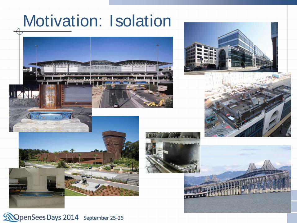
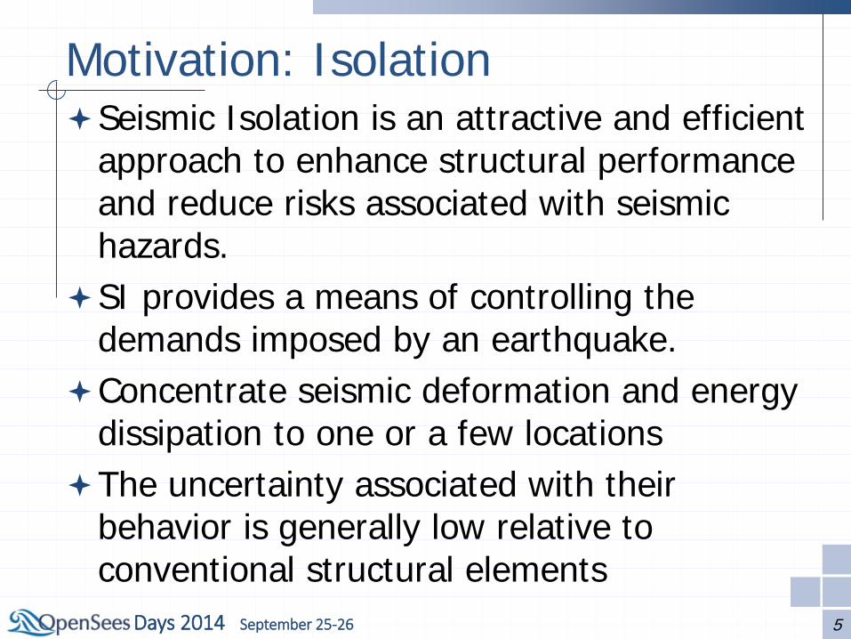
Motivation: Isolation Seismic Isolation is an attractive and efficient
approach to enhance structural performance and reduce risks associated with seismic hazards.
SI provides a means of controlling the demands imposed by an earthquake.
Concentrate seismic deformation and energy dissipation to one or a few locations
The uncertainty associated with their behavior is generally low relative to conventional structural elements
5
Days 2014 September 25-26
Motivation: Damping
Days 2014 September 25-26
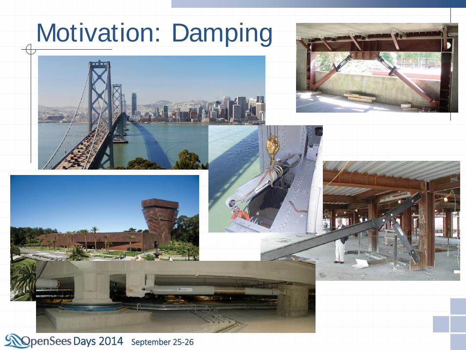
Motivation: Damping Supplemental viscous dampers can also
enhance structural performance and reduce risks associated with seismic hazards.
Supplemental damping provides a means of absorbing energy imposed by an earthquake.
Concentrate seismic energy dissipation at predetermined fuse locations
The uncertainty associated with their behavior is generally low relative to conventional structural elements
8
Days 2014 September 25-26
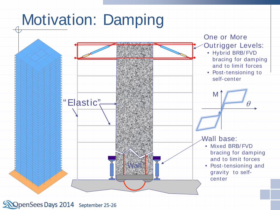
Wall
One or More Outrigger Levels: • Hybrid BRB/FVD
bracing for damping and to limit forces
• Post-tensioning to self-center
Wall base: • Mixed BRB/FVD
bracing for damping and to limit forces
• Post-tensioning and gravity to self-center
M θ “Elastic”
Motivation: Damping
Days 2014 September 25-26
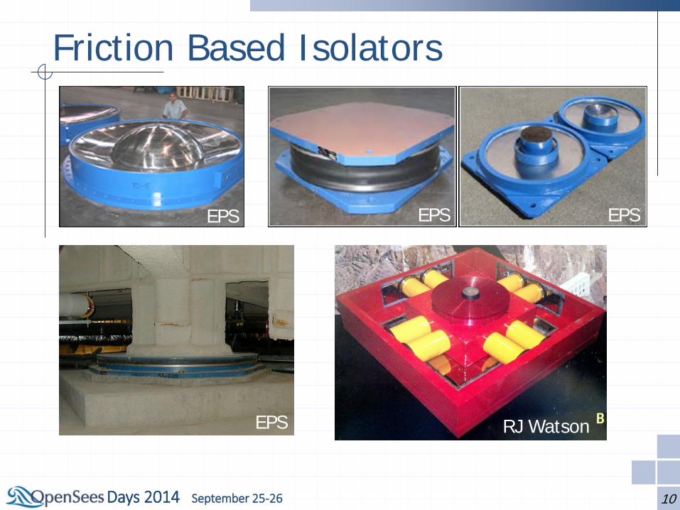
Friction Based Isolators
10
EPS EPS EPS
EPS RJ Watson
Days 2014 September 25-26
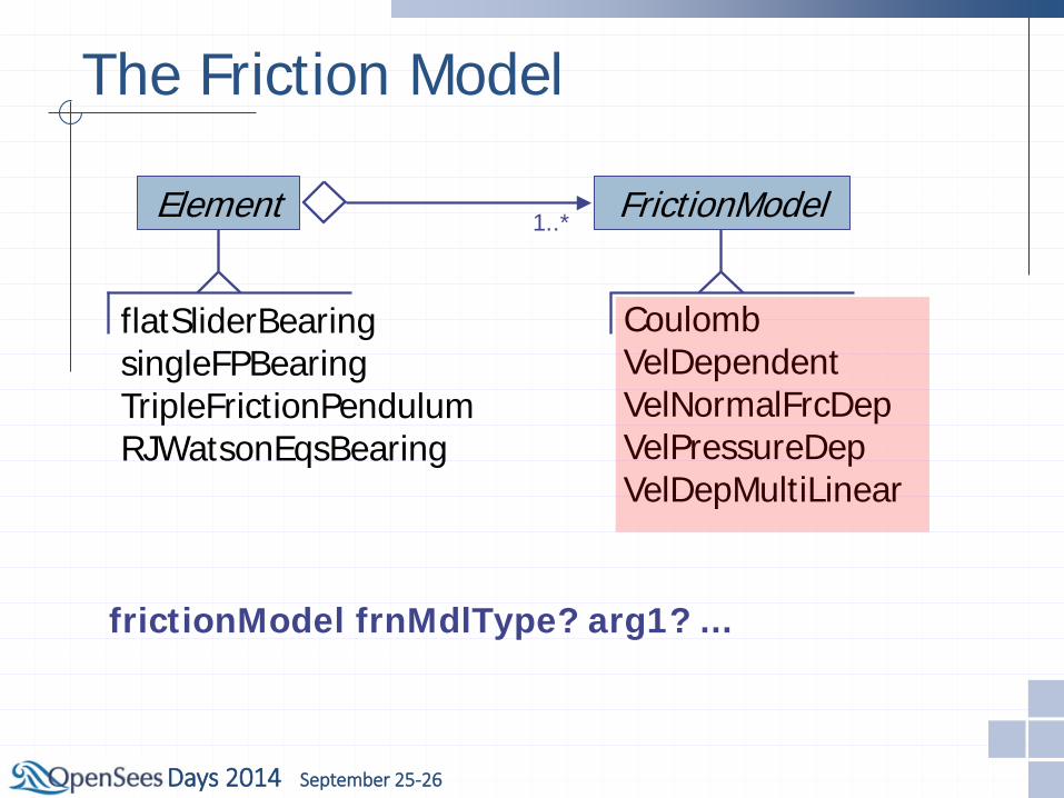
The Friction Model
Element
flatSliderBearing singleFPBearing TripleFrictionPendulum RJWatsonEqsBearing
FrictionModel 1..*
Coulomb VelDependent VelNormalFrcDep VelPressureDep VelDepMultiLinear
frictionModel frnMdlType? arg1? ...

Days 2014 September 25-26
The Friction Model
Coulomb VelDependent VelNormalFrcDep VelPressureDep VelDepMultiLinear
x
y
x
x
x
y
y
y
FrictionModel
Days 2014 September 25-26
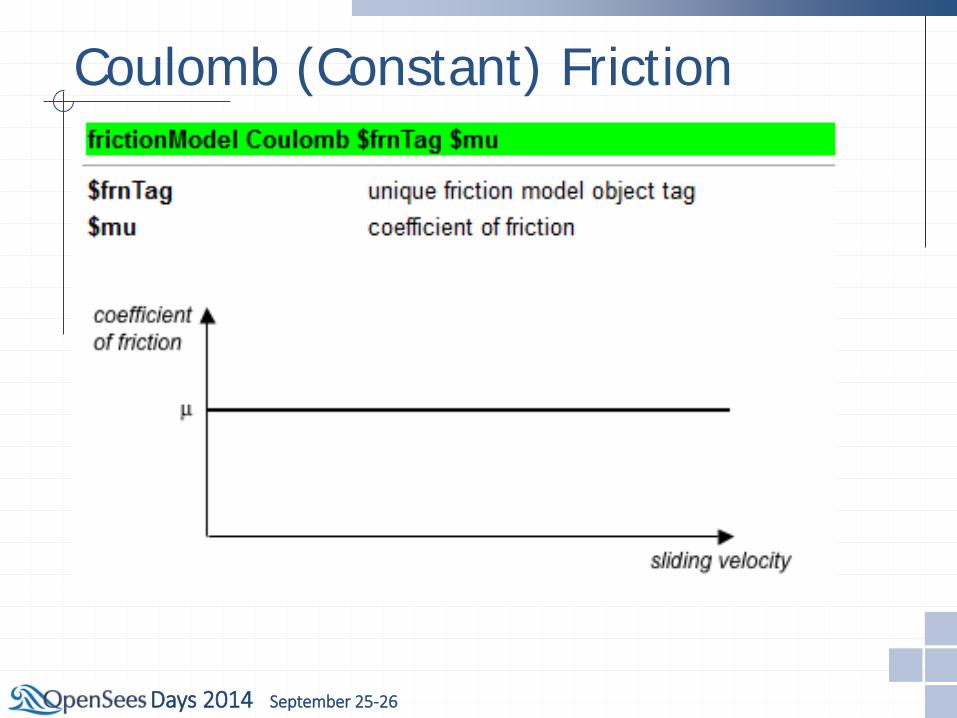
Coulomb (Constant) Friction
Days 2014 September 25-26
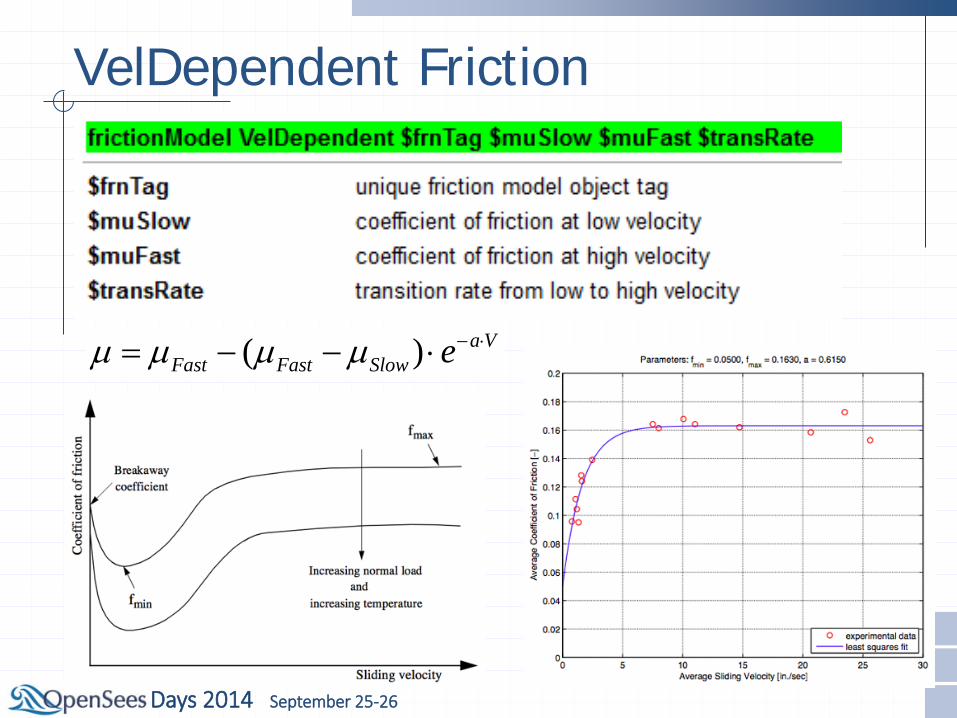
VelDependent Friction
( ) a VFast Fast Slow eµ µ µ µ − ⋅= − − ⋅
Days 2014 September 25-26
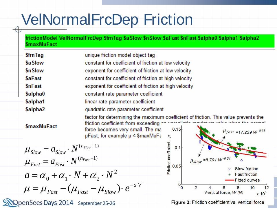
VelNormalFrcDep Friction
( 1)SlownSlow Slowa Nµ −= ⋅
( ) a VFast Fast Slow eµ µ µ µ − ⋅= − − ⋅
( 1)FastnFast Fasta Nµ −= ⋅
20 1 2a N Nα α α= + ⋅ + ⋅

Days 2014 September 25-26
VelNormalFrcDep Friction
Days 2014 September 25-26
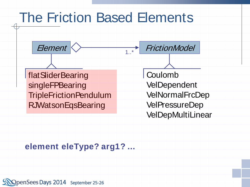
The Friction Based Elements
Element
flatSliderBearing singleFPBearing TripleFrictionPendulum RJWatsonEqsBearing
FrictionModel 1..*
Coulomb VelDependent VelNormalFrcDep VelPressureDep VelDepMultiLinear
element eleType? arg1? ...
Days 2014 September 25-26
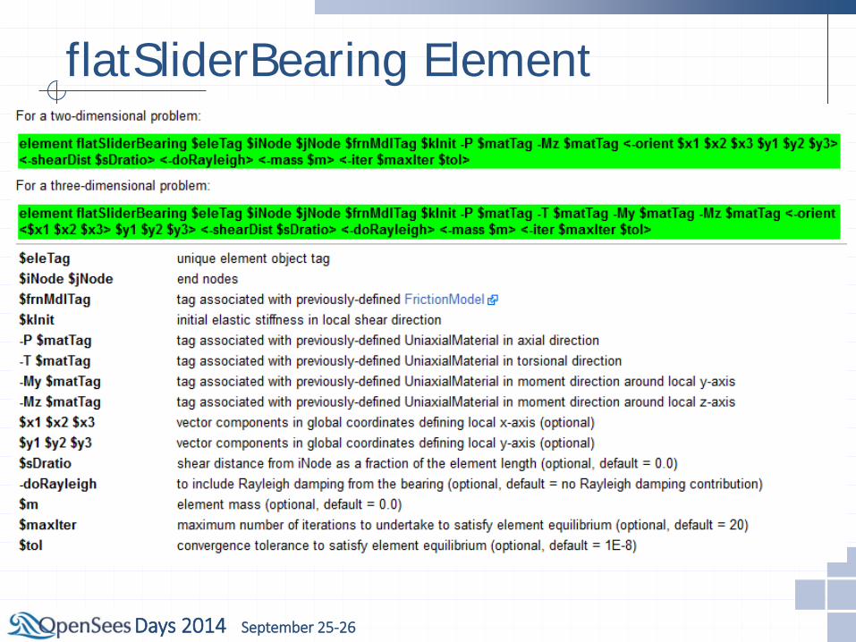
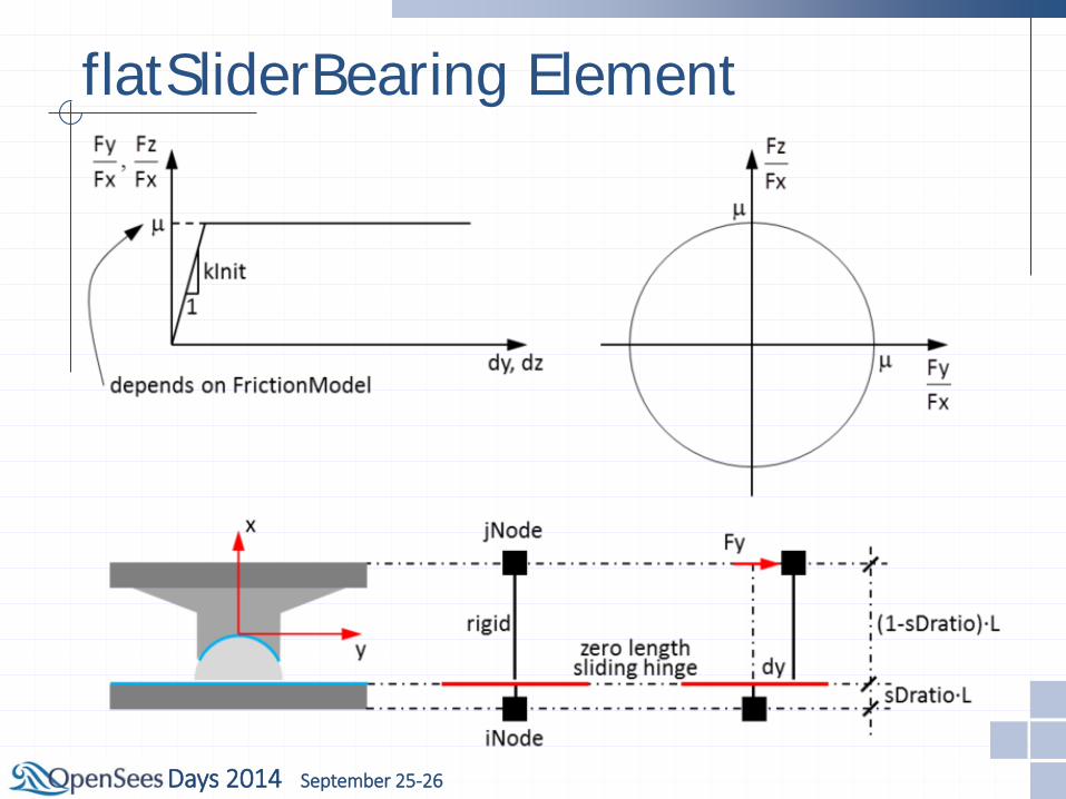
flatSliderBearing Element
Days 2014 September 25-26
flatSliderBearing Element

Days 2014 September 25-26
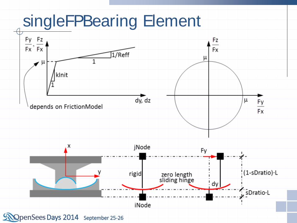
singleFPBearing Element
Days 2014 September 25-26
singleFPBearing Element
Days 2014 September 25-26
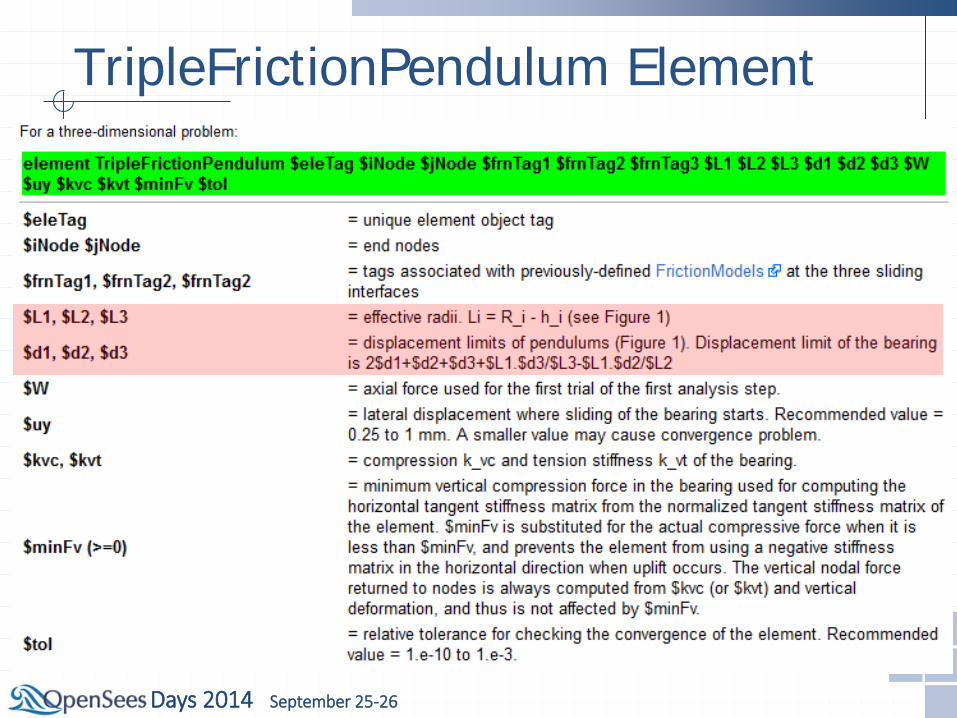
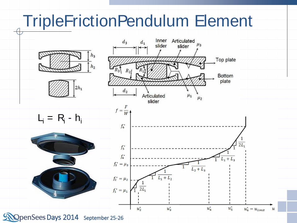
TripleFrictionPendulum Element
Days 2014 September 25-26
TripleFrictionPendulum Element
Li = Ri - hi
Days 2014 September 25-26
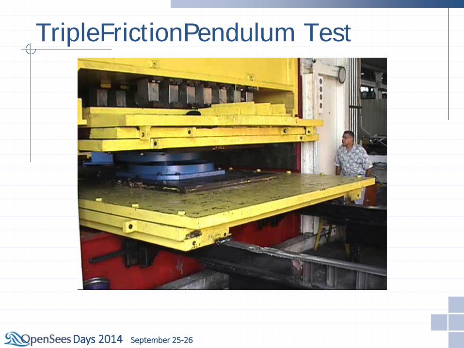
TripleFrictionPendulum Test

Days 2014 September 25-26
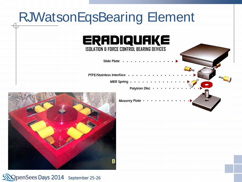
RJWatsonEqsBearing Element
Days 2014 September 25-26
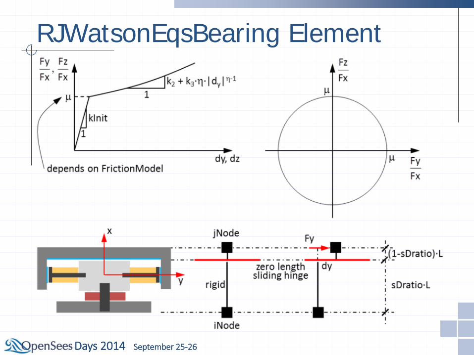
RJWatsonEqsBearing Element
Days 2014 September 25-26
RJWatsonEqsBearing Element
Days 2014 September 25-26
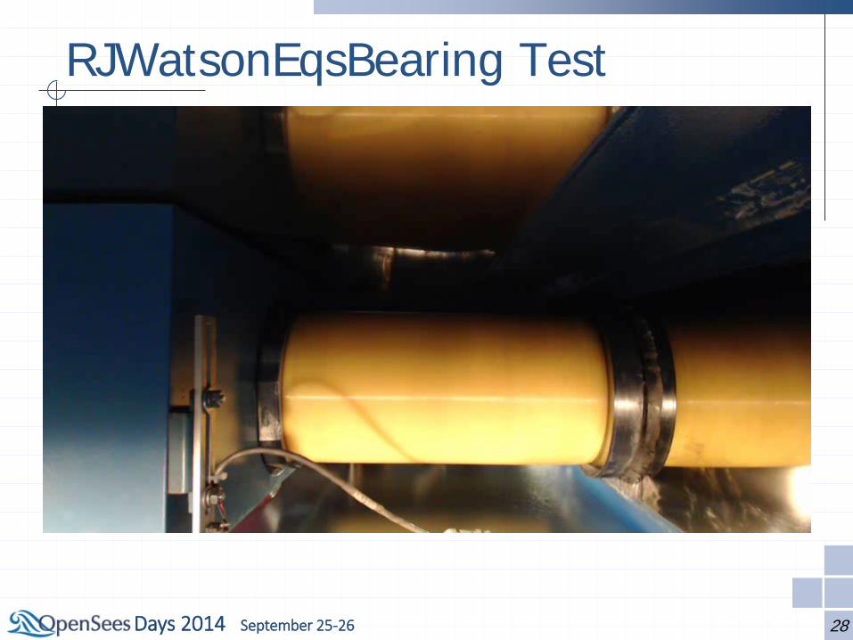
RJWatsonEqsBearing Test
28
Days 2014 September 25-26
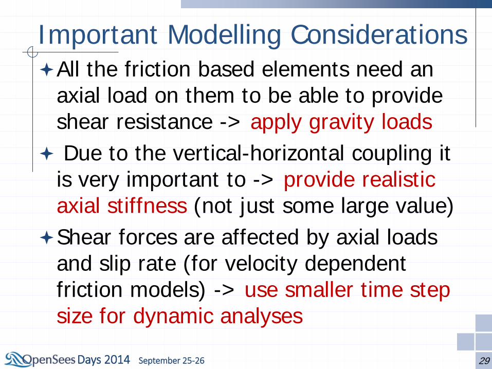
Important Modelling Considerations All the friction based elements need an
axial load on them to be able to provide shear resistance -> apply gravity loads
Due to the vertical-horizontal coupling it is very important to -> provide realistic axial stiffness (not just some large value)
Shear forces are affected by axial loads and slip rate (for velocity dependent friction models) -> use smaller time step size for dynamic analyses
29
Days 2014 September 25-26
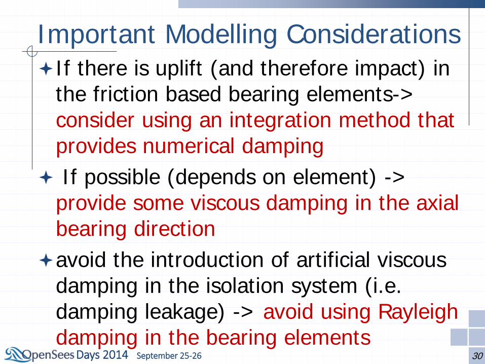
Important Modelling Considerations If there is uplift (and therefore impact) in
the friction based bearing elements-> consider using an integration method that provides numerical damping
If possible (depends on element) -> provide some viscous damping in the axial bearing direction
avoid the introduction of artificial viscous damping in the isolation system (i.e. damping leakage) -> avoid using Rayleigh damping in the bearing elements
30
Days 2014 September 25-26
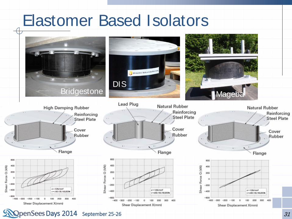
Elastomer Based Isolators
31
Bridgestone EPS EPS DIS
Mageba

Days 2014 September 25-26
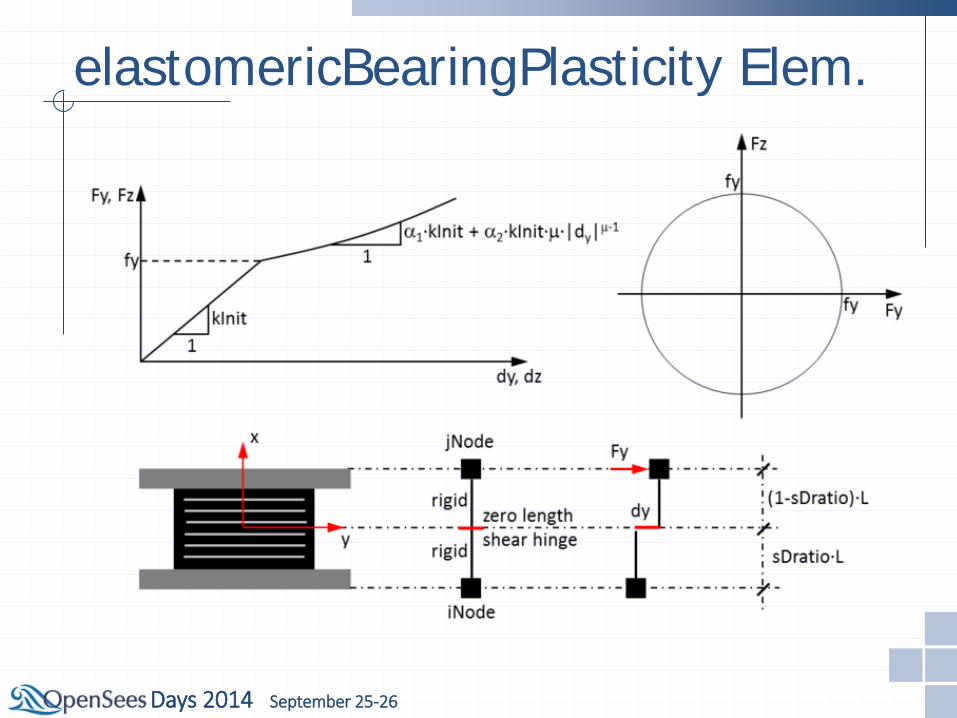
elastomericBearingPlasticity Elem.
Days 2014 September 25-26
elastomericBearingPlasticity Elem.

Days 2014 September 25-26
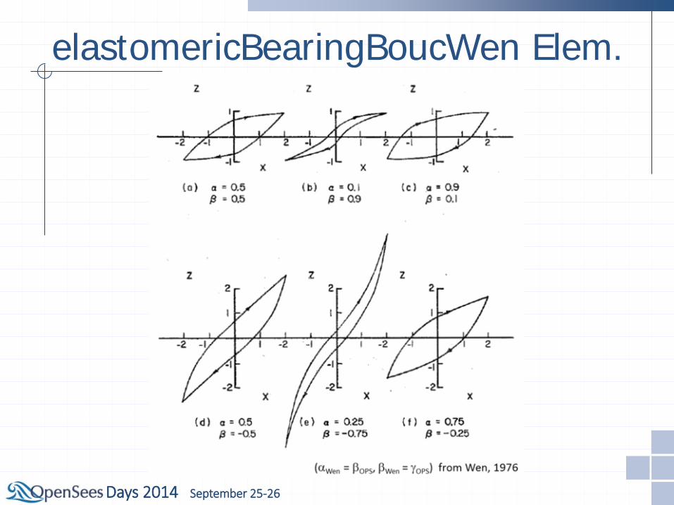
elastomericBearingBoucWen Elem.

Days 2014 September 25-26
elastomericBearingBoucWen Elem.
Days 2014 September 25-26
elastomericBearingBoucWen Elem.
Days 2014 September 25-26
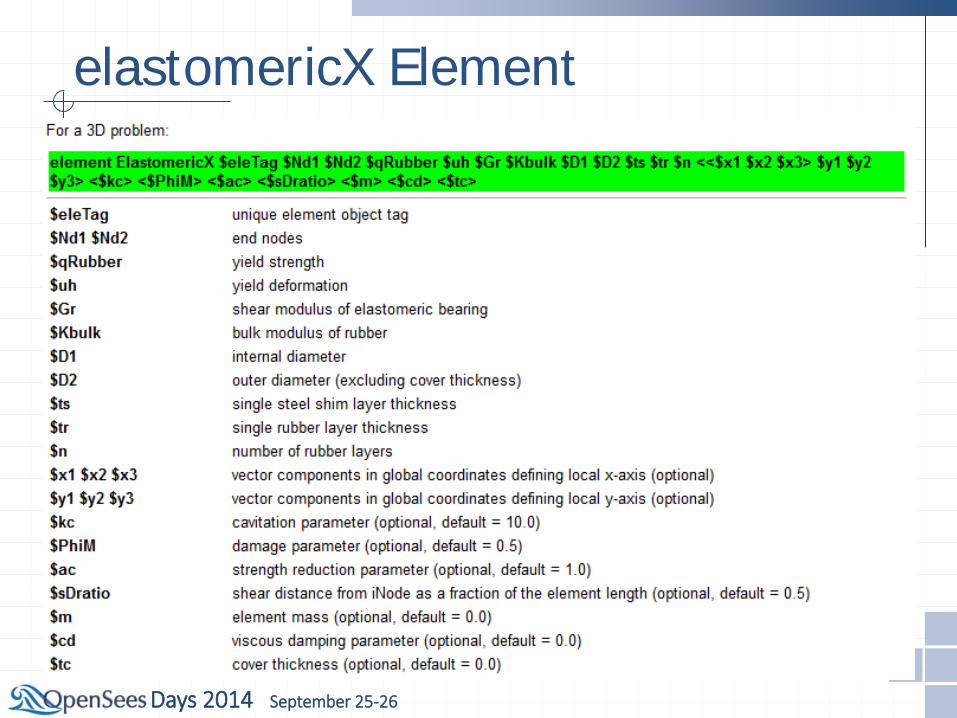
elastomericX Element

Days 2014 September 25-26
elastomericX Element Coupled bidirectional
motion in horizontal directions
Coupling of vertical and horizontal motion
Cavitation and post-cavitation behavior in tension
Strength degradation in cyclic tensile loading due to cavitation
Variation in critical buckling load capacity due to lateral displacement
Days 2014 September 25-26
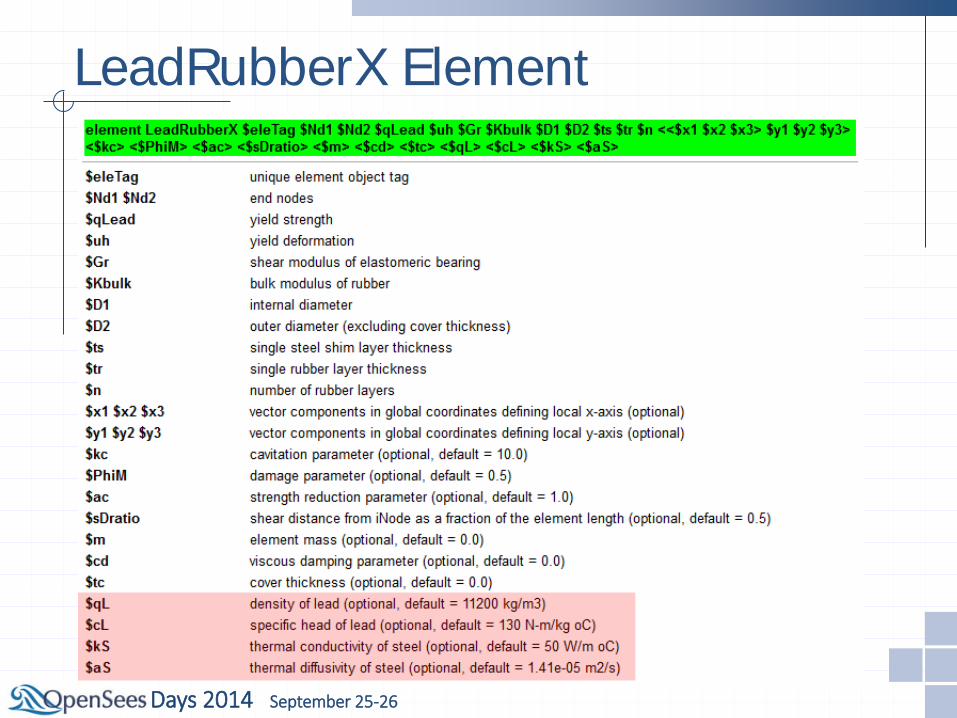
LeadRubberX Element

Days 2014 September 25-26
LeadRubberX Element Strength degradation in cyclic
shear loading due to heating of lead core
Coupled bidirectional motion in horizontal directions
Coupling of vertical and horizontal motion
Cavitation and post-cavitation behavior in tension
Strength degradation in cyclic tensile loading due to cavitation
Variation in critical buckling load capacity due to lateral displacement
Days 2014 September 25-26
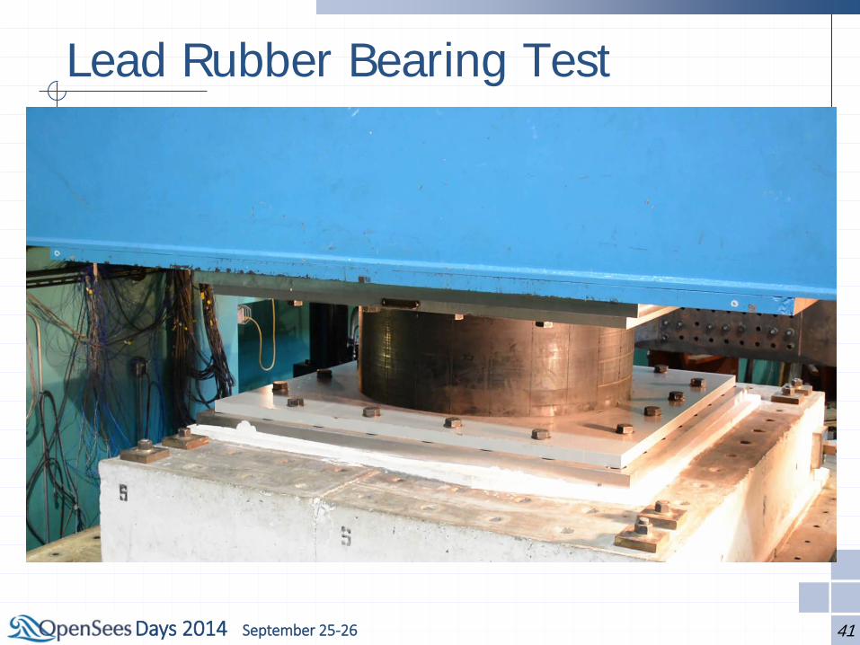
Lead Rubber Bearing Test
41

Days 2014 September 25-26
HDR Element
Days 2014 September 25-26
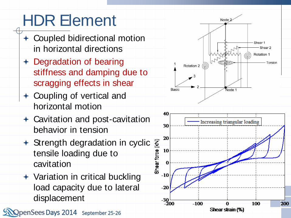
HDR Element Coupled bidirectional motion
in horizontal directions Degradation of bearing
stiffness and damping due to scragging effects in shear
Coupling of vertical and horizontal motion
Cavitation and post-cavitation behavior in tension
Strength degradation in cyclic tensile loading due to cavitation
Variation in critical buckling load capacity due to lateral displacement

Days 2014 September 25-26
KikuchiBearing Element
Days 2014 September 25-26
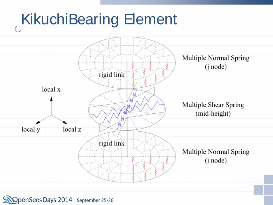
KikuchiBearing Element
Days 2014 September 25-26
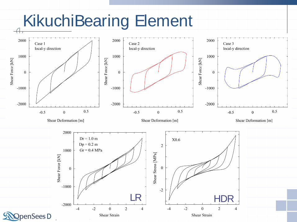
KikuchiBearing Element
LR HDR
Days 2014 September 25-26
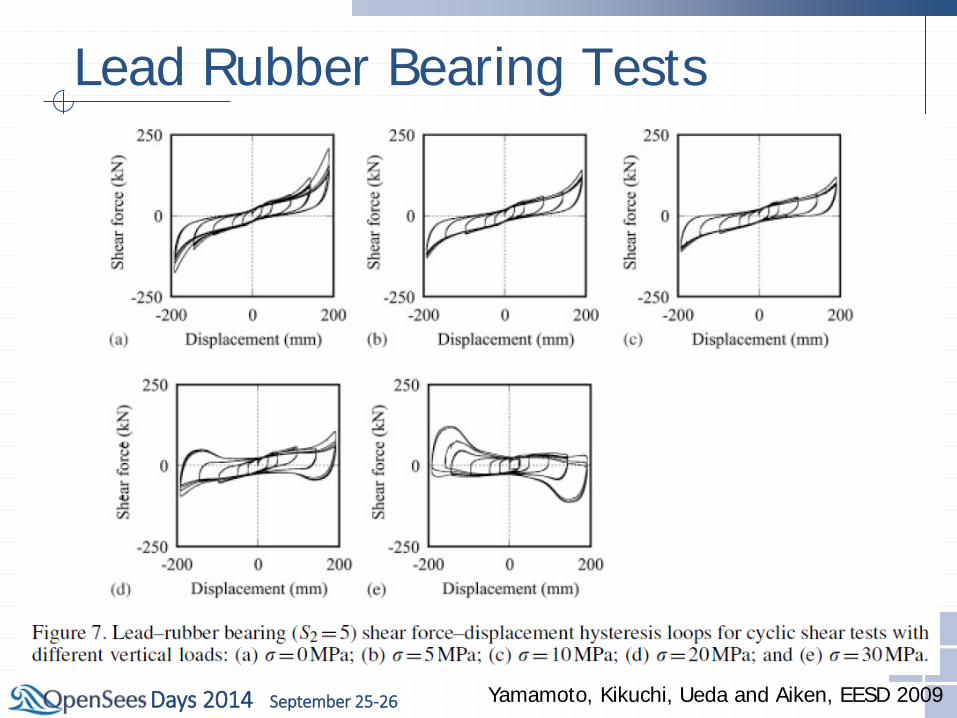
Lead Rubber Bearing Tests
Yamamoto, Kikuchi, Ueda and Aiken, EESD 2009
Days 2014 September 25-26
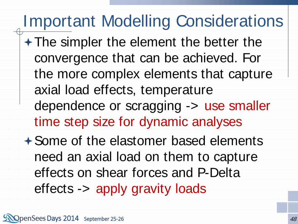
Important Modelling Considerations The simpler the element the better the
convergence that can be achieved. For the more complex elements that capture axial load effects, temperature dependence or scragging -> use smaller time step size for dynamic analyses
Some of the elastomer based elements need an axial load on them to capture effects on shear forces and P-Delta effects -> apply gravity loads
48

Days 2014 September 25-26
Important Modelling Considerations For all isolators it is very important to ->
provide realistic axial stiffness (not just some large value)
If possible (depends on element) -> provide some viscous damping in the axial bearing direction
Avoid the introduction of artificial viscous damping in the isolation system (i.e. damping leakage) -> avoid using Rayleigh damping in the bearing elements
49
Days 2014 September 25-26
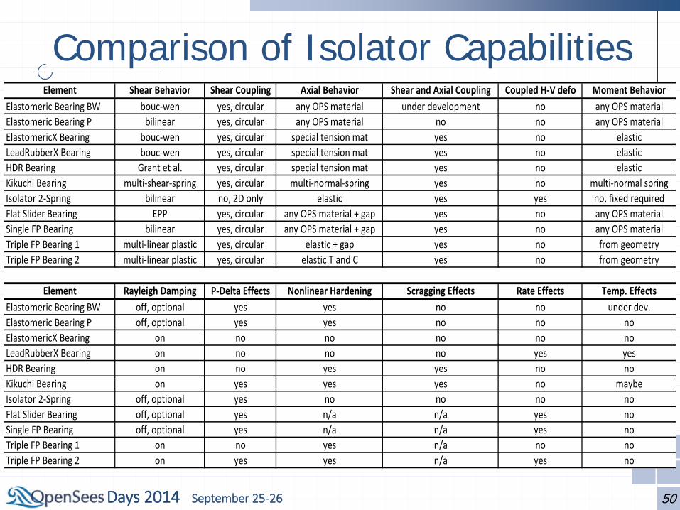
Comparison of Isolator Capabilities
50
Element Shear Behavior Shear Coupling Axial Behavior Shear and Axial Coupling Coupled H-V defo Moment BehaviorElastomeric Bearing BW bouc-wen yes, circular any OPS material under development no any OPS materialElastomeric Bearing P bilinear yes, circular any OPS material no no any OPS materialElastomericX Bearing bouc-wen yes, circular special tension mat yes no elasticLeadRubberX Bearing bouc-wen yes, circular special tension mat yes no elasticHDR Bearing Grant et al. yes, circular special tension mat yes no elasticKikuchi Bearing multi-shear-spring yes, circular multi-normal-spring yes no multi-normal springIsolator 2-Spring bilinear no, 2D only elastic yes yes no, fixed requiredFlat Slider Bearing EPP yes, circular any OPS material + gap yes no any OPS materialSingle FP Bearing bilinear yes, circular any OPS material + gap yes no any OPS materialTriple FP Bearing 1 multi-linear plastic yes, circular elastic + gap yes no from geometryTriple FP Bearing 2 multi-linear plastic yes, circular elastic T and C yes no from geometry
Element Rayleigh Damping P-Delta Effects Nonlinear Hardening Scragging Effects Rate Effects Temp. EffectsElastomeric Bearing BW off, optional yes yes no no under dev.Elastomeric Bearing P off, optional yes yes no no noElastomericX Bearing on no no no no noLeadRubberX Bearing on no no no yes yesHDR Bearing on no yes yes no noKikuchi Bearing on yes yes yes no maybeIsolator 2-Spring off, optional yes no no no noFlat Slider Bearing off, optional yes n/a n/a yes noSingle FP Bearing off, optional yes n/a n/a yes noTriple FP Bearing 1 on no yes n/a no noTriple FP Bearing 2 on yes yes n/a yes no
Days 2014 September 25-26
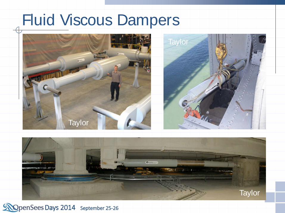
Fluid Viscous Dampers
Taylor
Taylor
Taylor
Days 2014 September 25-26
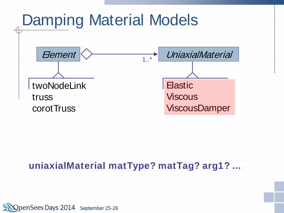
Damping Material Models
Element
twoNodeLink truss corotTruss
UniaxialMaterial 1..*
Elastic Viscous ViscousDamper
uniaxialMaterial matType? matTag? arg1? ...
Days 2014 September 25-26
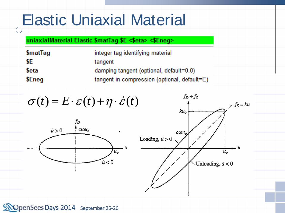
Elastic Uniaxial Material
( ) ( ) ( )t E t tσ ε η ε= ⋅ + ⋅
Days 2014 September 25-26
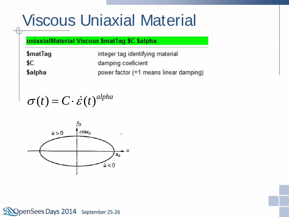
Viscous Uniaxial Material
( ) ( )alphat C tσ ε= ⋅
Days 2014 September 25-26
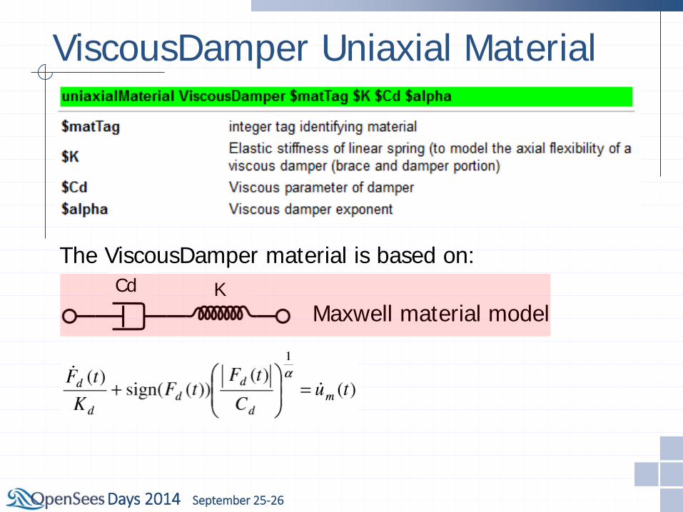
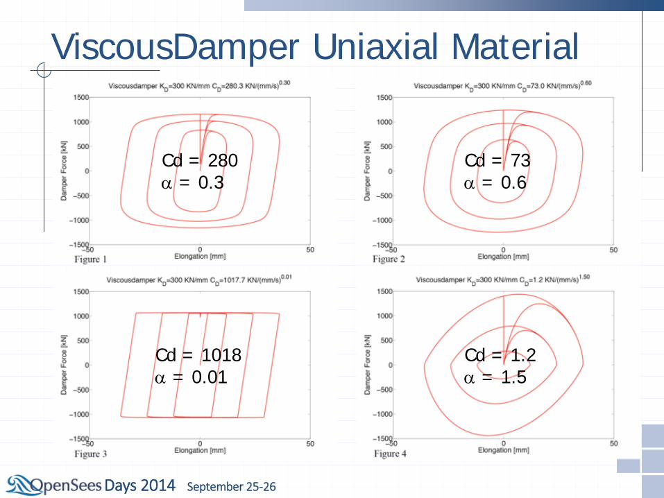
ViscousDamper Uniaxial Material
Cd K Maxwell material model
The ViscousDamper material is based on:
Days 2014 September 25-26
ViscousDamper Uniaxial Material
Cd = 280 α = 0.3
Cd = 73 α = 0.6
Cd = 1018 α = 0.01
Cd = 1.2 α = 1.5

Days 2014 September 25-26
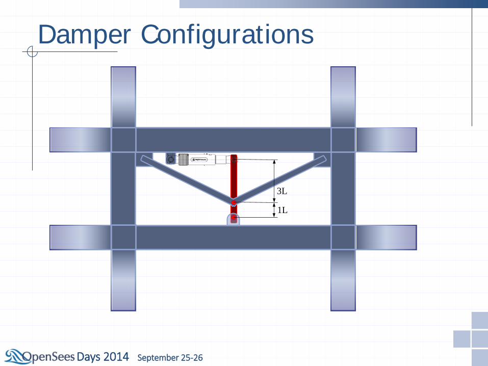
Damper Configurations
Days 2014 September 25-26
3L
1L
Damper Configurations
Days 2014 September 25-26
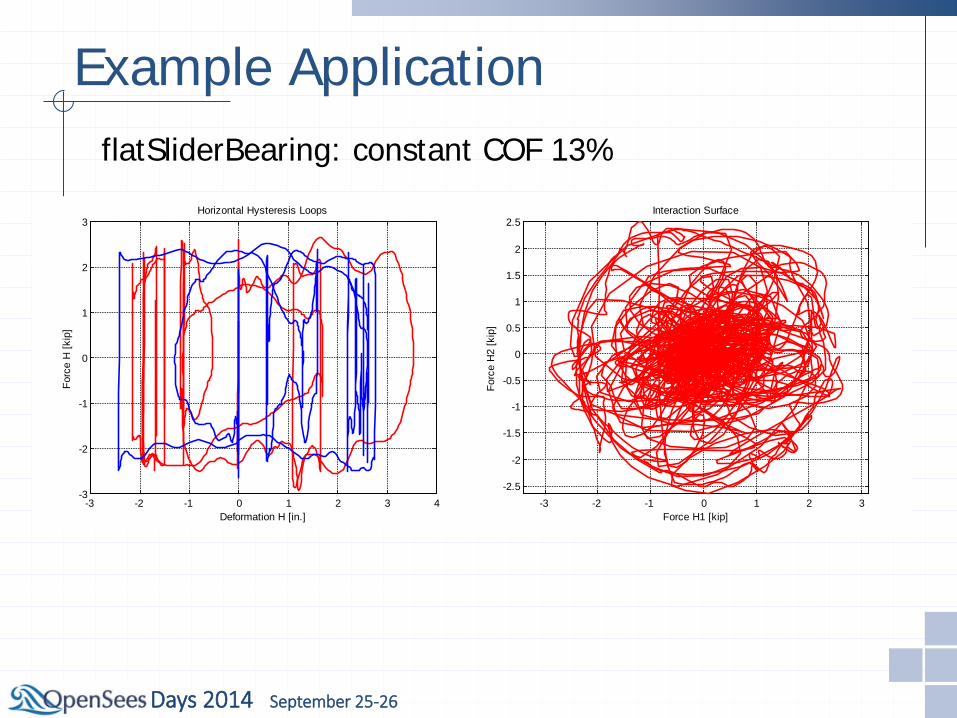
Example Application flatSliderBearing: constant COF 13%
-3 -2 -1 0 1 2 3 4-3
-2
-1
0
1
2
3
Deformation H [in.]
Forc
e H
[kip
]
Horizontal Hysteresis Loops
-2 -1 0 1 2 3
-2
-1.5
-1
-0.5
0
0.5
1
1.5
2
2.5
Displacement H1 [in.]
Dis
plac
emen
t H2
[in.]
Displacement Orbit
-3 -2 -1 0 1 2 3-2.5
-2
-1.5
-1
-0.5
0
0.5
1
1.5
2
2.5
Force H1 [kip]
Forc
e H
2 [k
ip]
Interaction Surface

Days 2014 September 25-26
-5 -4 -3 -2 -1 0 1 2 3 4
-3
-2
-1
0
1
2
3
4
Displacement H1 [in.]D
ispl
acem
ent H
2 [in
.]
Displacement Orbit
-4 -3 -2 -1 0 1 2 3 4 5-5
-4
-3
-2
-1
0
1
2
3
4
Deformation H [in.]
Forc
e H
[kip
]
Horizontal Hysteresis Loops
Example Application singleFPBearing: constant COF 13%
-5 -4 -3 -2 -1 0 1 2 3 4
-4
-3
-2
-1
0
1
2
3
Force H1 [kip]Fo
rce
H2
[kip
]
Interaction Surface
Days 2014 September 25-26
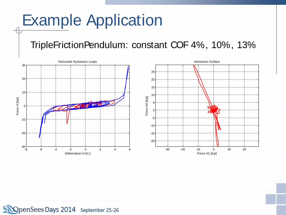
Example Application TripleFrictionPendulum: constant COF 4%, 10%, 13%
-8 -6 -4 -2 0 2 4 6-30
-20
-10
0
10
20
30
Deformation H [in.]
Forc
e H
[kip
]
Horizontal Hysteresis Loops
-6 -4 -2 0 2 4 6-6
-4
-2
0
2
4
Displacement H1 [in.]D
ispl
acem
ent H
2 [in
.]
Displacement Orbit
-30 -20 -10 0 10 20
-20
-15
-10
-5
0
5
10
15
20
25
Force H1 [kip]
Forc
e H
2 [k
ip]
Interaction Surface
Days 2014 September 25-26
-5 -4 -3 -2 -1 0 1 2 3 4
-3
-2
-1
0
1
2
3
4
Displacement H1 [in.]D
ispl
acem
ent H
2 [in
.]
Displacement Orbit
-5 -4 -3 -2 -1 0 1 2 3 4
-4
-3
-2
-1
0
1
2
3
Force H1 [kip]Fo
rce
H2
[kip
]
Interaction Surface
-4 -3 -2 -1 0 1 2 3 4 5-5
-4
-3
-2
-1
0
1
2
3
4
Deformation H [in.]
Forc
e H
[kip
]
Horizontal Hysteresis Loops
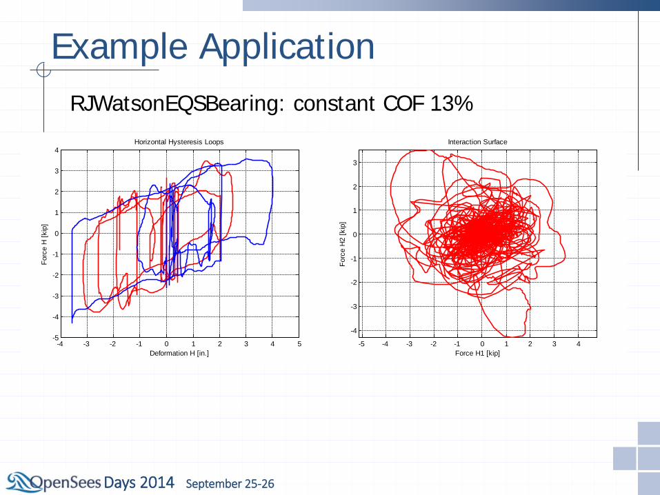
Example Application RJWatsonEQSBearing: constant COF 13%
Days 2014 September 25-26
-8 -6 -4 -2 0 2 4 6 8
-4
-2
0
2
4
6
Displacement H1 [in.]D
ispl
acem
ent H
2 [in
.]
Displacement Orbit
-6 -4 -2 0 2 4 6 8-6
-4
-2
0
2
4
6
8
Deformation H [in.]
Forc
e H
[kip
]
Horizontal Hysteresis Loops
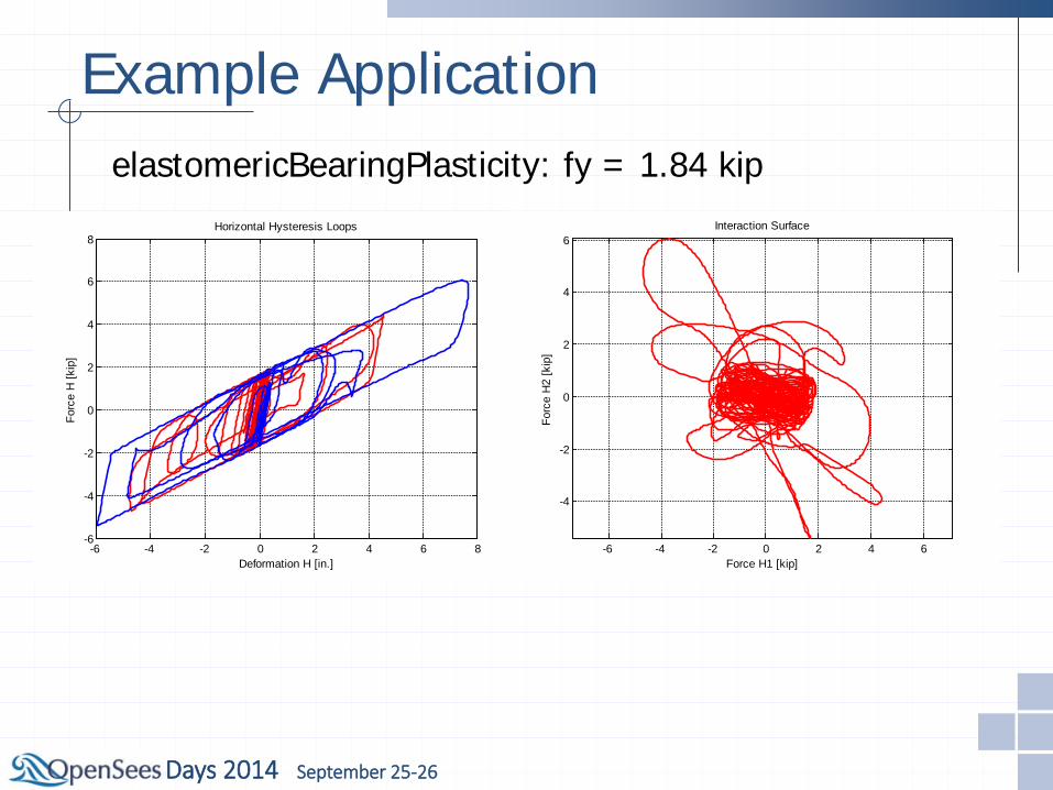
Example Application elastomericBearingPlasticity: fy = 1.84 kip
-6 -4 -2 0 2 4 6
-4
-2
0
2
4
6
Force H1 [kip]Fo
rce
H2
[kip
]
Interaction Surface

Days 2014 September 25-26
-8 -6 -4 -2 0 2 4 6 8
-4
-2
0
2
4
6
Displacement H1 [in.]D
ispl
acem
ent H
2 [in
.]
Displacement Orbit
-6 -4 -2 0 2 4 6 8-6
-4
-2
0
2
4
6
8
Deformation H [in.]
Forc
e H
[kip
]
Horizontal Hysteresis Loops
Example Application elastomericBearingBoucWen: fy = 1.84 kip
-6 -4 -2 0 2 4 6
-4
-2
0
2
4
6
Force H1 [kip]Fo
rce
H2
[kip
]
Interaction Surface
Days 2014 September 25-26
-6 -4 -2 0 2 4 6
-4
-3
-2
-1
0
1
2
3
4
5
6
Displacement H1 [in.]D
ispl
acem
ent H
2 [in
.]
Displacement Orbit
-6 -4 -2 0 2 4 6 8-6
-4
-2
0
2
4
6
Deformation H [in.]
Forc
e H
[kip
]
Horizontal Hysteresis Loops
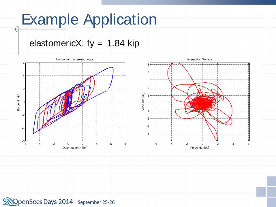
Example Application elastomericX: fy = 1.84 kip
-6 -4 -2 0 2 4 6
-4
-3
-2
-1
0
1
2
3
4
5
Force H1 [kip]Fo
rce
H2
[kip
]
Interaction Surface

Days 2014 September 25-26
-6 -4 -2 0 2 4 6
-4
-3
-2
-1
0
1
2
3
4
5
Displacement H1 [in.]D
ispl
acem
ent H
2 [in
.]
Displacement Orbit
-6 -4 -2 0 2 4 6-6
-4
-2
0
2
4
6
Deformation H [in.]
Forc
e H
[kip
]
Horizontal Hysteresis Loops
Example Application LeadRubberX: qd = 1.66 kip
-6 -4 -2 0 2 4 6
-4
-3
-2
-1
0
1
2
3
4
5
Force H1 [kip]
Forc
e H
2 [k
ip]
Interaction Surface
Days 2014 September 25-26
Conclusions OpenSees already provides a fairly large
library of elements and materials that can be used to model isolators and viscous dampers.
However, isolator capabilities need to be further improved to include important effects such as the coupled vertical-horizontal deformation effects.
Additional models for capturing temperature effects should be developed.
Modeling of isolator failures and moat impact needs to be investigated.
67
Open System for Earthquake Engineering Simulation Pacific Earthquake Engineering Research Center
Questions? Thank you!