Embed Size (px)
Citation preview

Int j simul model 19 (2020) 1, 100-111
ISSN 1726-4529 Original scientific paper
https://doi.org/10.2507/IJSIMM19-1-506 100
MODELLING THE INFLUENCE OF INLET ANGLE CHANGE
ON THE PERFORMANCE OF SUBMERSIBLE WELL PUMPS
Wang, H. L.*; Long, B.
*; Yang, Y.
**; Xiao, Y.
** & Wang, C.
***,#
* School of Aerospace and Mechanical Engineering/Flight College, Changzhou Institute of
Technology, Changzhou, 213032, China ** National Research Center of Pumps, Jiangsu University, Zhenjiang, 212013, China
*** College of Hydraulic Science and Engineering, Yangzhou University, Yangzhou, 225009, China
E-Mail: [email protected] (# Corresponding author)
Abstract
Three groups of schemes were designed for different blade inlet angles of impellers to improve the
efficiency and single-stage head of submersible well pumps. Furthermore, the hydraulic performance
of the pumps was analysed using ANSYS CFX. As a result, the heads and efficiencies of the schemes
were acquired. The internal flow fields of the schemes under different flow quantities were analysed,
and the accuracy of the optimal scheme was experimentally verified. Results indicated that enlarging
the inlet angle of the blade of submersible well pumps might improve the hydraulic performance to a
certain degree. In comparison with the general design scheme with a fixed inlet angle that with an inlet
angle was 26° at the front cover plate and 20° at the rear cover plate, and that in the middle was under
uniform change. The incoming flow angle of the medium coincided with the inlet angle; thus, the
discharge capacity of the pump had a high matching ratio with the actual discharge capacity. The head
and efficiency improved remarkably relative to the initial model, and thus, the hydraulic performance
of the pump improved. (Received in November 2019, accepted in March 2020. This paper was with the authors 2 months for 1 revision.)
Key Words: Submersible Well Pumps, Inlet Angle, Hydraulic Design, Internal Flow Field
1. INTRODUCTION
As the core equipment used to extract underground water, submersible well pumps have
broad application prospect in various fields, such as agricultural irrigation, sewage treatment,
and oilfield exploitation [1-3]. Hydraulic performance [4-6] is an important index for
evaluating pump performance, and the performance loss caused by the inappropriate selection
of many geometric parameters considerably affect hydraulic performance [7-8]. Bacharoudis
et al. [9] analysed the performance of impellers with different blade outlet angles under the
same outlet diameter. Then, these scholars calculated the flow conditions in the blade channel,
analysed and summarized the prediction curve and calculation results of the internal flow
field, and selected the optimal parameters to improve the hydraulic performance. Currently,
submersible well pumps are usually designed via numerical simulation [10-12], the hydraulic
loss method, and an approximation model.
On this basis, research scholars have explored the influence of the design parameters of
submersible well pumps on hydraulic performance [13-15]. However, few in-depth studies
regarding the hydraulic performance of submersible well pumps have been performed based
on the design of the inlet angle of the impeller. Therefore, the influence of the inlet angle
design of submersible well pumps and the change in flow field must be investigated. Design
schemes with different inlet angles are selected, and CFD software was used to perform the
numerical calculation and investigate the external characteristics of internal flow field in these
schemes. The hydraulic performance of the schemes is then compared to guide submersible
well pump designers with a theoretical design.

Wang, Long, Yang, Xiao, Wang: Modelling the Influence of Inlet Angle Change on the …
101
2. STATE OF THE ART
Many experts and scholars worldwide have conducted substantial research on the influence of
the design parameters of centrifugal pumps on hydraulic design. Stel et al. [16] used the
numerical simulation method to investigate a multistage submersible pump and discovered that
the accurate hydraulic performance of pumps above three stages could be acquired through
the numerical simulation of a three-stage pump. On this basis, the present study conducted a
numerical simulation analysis and research on submersible well pumps and investigated the
hydraulic performance of three-stage submersible well pumps. El-Gazzar and Hawash [17]
studied the design method of improving hydraulic performance through the impeller blade
splitting method of a centrifugal pump; however, the eccentricity problem caused by this
method influenced the rotation centre of the pump to some degree, resulting in a great
vibration amplitude and increase in radial force. Only blade placement was considered in the
present study, but the structural changes caused by the change of each segment of the splitter
blade angle were not associated. Gölcü et al. [18] studied the influence of a splitter blade in a
deep-well pump on hydraulic performance. Then, these scholars conducted a comparative
analysis of the influences of the changes in quantity and length of the splitter blades on the
performance through numerical simulation. The results revealed that splitter blades of a certain
quantity and 80 % blade length could effectively elevate the head, but excessive splitter blades
would block the flow channel and reduce pump efficiency. The overall placement of splitter
blades was investigated without an intensive analysis of whether the placement angles of the
original and splitter blades could weaken the blocking problem to a certain degree while
elevating the head. Wei and Sun [19] studied the influence of the diffuser inlet’s width on the
performance of submersible pumps and found that increases of the inlet’s width could
effectively offset the large energy, reduce the hydraulic loss of the diffuser, and improve the
hydraulic efficiency of the entire pump as the inlet width increases. However, multistage
impellers in submersible well pumps are interconnected by diffusers; thus, the flow field
distribution at the impeller inlet since the second stage is determined by the diffuser design
quality, whereas quality influences the hydraulic performance of the multistage submersible
pump. Ajay et al. [20] optimized the impeller shape based on many optimization algorithms
and predicted the optimization result by comparing the head losses, thereby reducing
experimental time to a certain degree. Based on this method, a follow-up research was
conducted in simultaneous consideration of the blade inlet and outlet angles. Lu et al. [21]
conducted an experimental study that combined the orthogonal, grey correlation, and self-
priming time tests to investigate the influencing factors of the self-priming time of a
multistage self-priming centrifugal pump and shorten the corresponding self-priming time.
However, the influence of impeller blade inlet parameters on self-priming performance was
not analysed. In order to improve the hydrodynamic performance of the centrifugal pump,
Zhou et al. [22] made an orthogonal experiment to optimize the impeller design parameters.
Five main impeller geometric parameters were chosen as the research factors, and 16
impellers were designed. Through the variance analysis method, the best parameter
combination for higher efficiency was captured finally. However, the 16 impellers equipped
with the same volute. The matching of impeller and guide vane was not studied. Kim et al.
[23] implemented an optimization design of the inlet and outlet angles of the blades of a
centrifugal pump impeller based on the response surface method, thereby effectively
improving hydraulic efficiency. However, optimization was only achieved by setting fixed
values of the inlet and outlet angles at the intersecting lines of the blade’s front and rear cover
plates; the influence of the possible linear change from the intersecting line of the front cover
plate to that of the rear cover plate on the hydraulic performance of the pump was not
considered. Li et al. [24] studied the rotor-stator interaction mechanism in impeller and guide
vanes of mixed-flow pump under part loading condition, the flow field between the impeller

Wang, Long, Yang, Xiao, Wang: Modelling the Influence of Inlet Angle Change on the …
102
outlet and the guide vane inlet under part loading condition was measured based on Particle
Image Velocimetry (PIV). The research results provide significant reference value for
revealing the internal flow characteristics under part loading condition as well as for
optimization of mixed-flow pump. Influence of rotor-stator interaction on the flow in the area
between the impeller outlet and the guide vane inlet was analysed according to the
combination of the velocity and the vorticity distribution in the related area. However, the
characteristic hydrodynamic structure of the rotor-stator interaction area was not suitable for
submersible well pumps. Capurso et al. [25] proposed a novel impeller designed for low-
medium specific speed double suction centrifugal pumps, and found that the novel double
suction impeller was characterized by a new arrangement of its flow channels, which come up
alternately on the same circumferential exit even if they started from the two different sides.
However, higher hydraulic blade loading should be designed to explore performance and the
efficiency of the new geometry and to correlate the number of blades with the slip factor
value for the novel design. Jiang et al. [26] analysed the influence of the axial dimensional
error of the impeller and the guide vane on the external performance and internal flow of the
pump. The results revealed that when the diffuser inlet width is less than the impeller outlet
width, an increase in the diffuser inlet width always causes a reduction in the pump head, and
the pump efficiency increases at a small flow rate but decreases at a large flow rate. However,
the matching design method of impeller and diffuser was needed more experimental
verification. Namazizadeh et al. [27] optimized the impeller of a centrifugal pump by
investigating the effect of adding splitter blades and modifying their geometry. Using Design
of Experiment (DoE) technique, the design space was created and response surface method
was utilized to find the optimum geometry. The results showed adding splitters could improve
total head by about 10.6 % and by modifying the geometry using DoE technique it could
increase further by 4.4 % with the negligible effect on the pump overall efficiency. However,
more different parameters should be considered and using Box-Behnken technique in DoE.
More research was needed in the applicability of second order polynomial curves.
The above research results were mainly based on the numerical simulation prediction and
optimization design of the internal structure of centrifugal pumps. However, most research on
the inlet and outlet angles of impeller blades were under the uniform change situation.
Research on the influence of inlet angle under a linear change on the hydraulic performance
of submersible well pumps, although few, has been conducted. The optimization of the
impeller blade is crucial to the control of the inlet flow field loss of the impeller and the
hydraulic performance of the impeller channel. Therefore, a fluid computational domain
model was established via numerical simulation. Starting from the influences of pump
impeller parameters on the overall pump performance, this study explored the influence
characteristics of different designed blade inlet angles on impeller performance and even the
overall performance of submersible well pumps.
The remainder of this study is arranged as follows: Section 3 discusses the modelling for
pump parameter optimization and mesh generation and the hydraulic performance analysis
under multiple working conditions. Section 4 obtains the optimal scheme and the mechanism
of parameter optimization through a comparative analysis of the flow fields and test data of
different schemes. Section 5 summarizes the study and provides the conclusions.
3. METHODOLOGY
3.1 Geometric model
A 200QJ50 submersible well pump was taken as the study object, and a three-stage pump was
taken as the calculation model. The hydraulic models of the impeller and the diffuser at each
stage were the same. Their design parameters were as follows: rotation speed n = 2850 r/min,

Wang, Long, Yang, Xiao, Wang: Modelling the Influence of Inlet Angle Change on the …
103
design flow quantity Qdes = 50 m3/h, single-stage head H = 17 m, specific speed ns = 146.43
(calculated in accordance with a single-stage head), outlet diameter D2 = 134 mm, outlet width
b2 = 16 mm, number of impeller blades Z = 6, and outlet angle β2 = 20.5°. A three-dimensional
model of the impeller and the diffuser is shown in Fig. 1.
Figure 1: Three-dimensional model of the impeller and the diffuser.
Three different impeller inlet angle schemes were selected. The performance change of
this submersible well pump under the three schemes and the distribution difference of the
internal flow field were analysed through numerical calculation. The results provide a certain
theoretical reference for the inverse design methods of submersible well pumps.
Among the three inlet angle schemes, the impeller inlet angle under the first scheme
presented a continuously decreasing trend from the front cover plate to the rear cover plate;
the inlet angle was 26° at the front cover plate and 20° at the rear cover plate, and that in the
middle was under uniform change. The inlet angle under the second scheme was constant at
26°, and that under the third scheme was 20°. Table I shows the abovementioned inlet angle
design schemes.
Table I: Design scheme of the inlet blade angle.
Scheme Inlet angle β1
Front cover Cover plate
1 26° 20°
2 26° 26°
3 20° 20°
3.2 Numerical simulation
ANSYS ICEM was used to generate high-quality hexahedral meshes in the computational
domains of submersible well pumps because of the considerable effect of mesh quality on the
numerical calculation. The meshes were added to each boundary while guaranteeing the quality
of each part. Most submersible well pumps are multistage pumps with numerous meshes. Mesh
independence analysis must be performed to guarantee calculation accuracy and improve
calculation efficiency. Scheme 1 was selected for mesh generation and independence analysis.
Fig. 2 shows a schematic of the computational meshes. The left side shows the single-channel
meshes of the impeller, whereas the right side shows the single-channel meshes of the diffuser.
Figure 2: Mesh of the single channels.
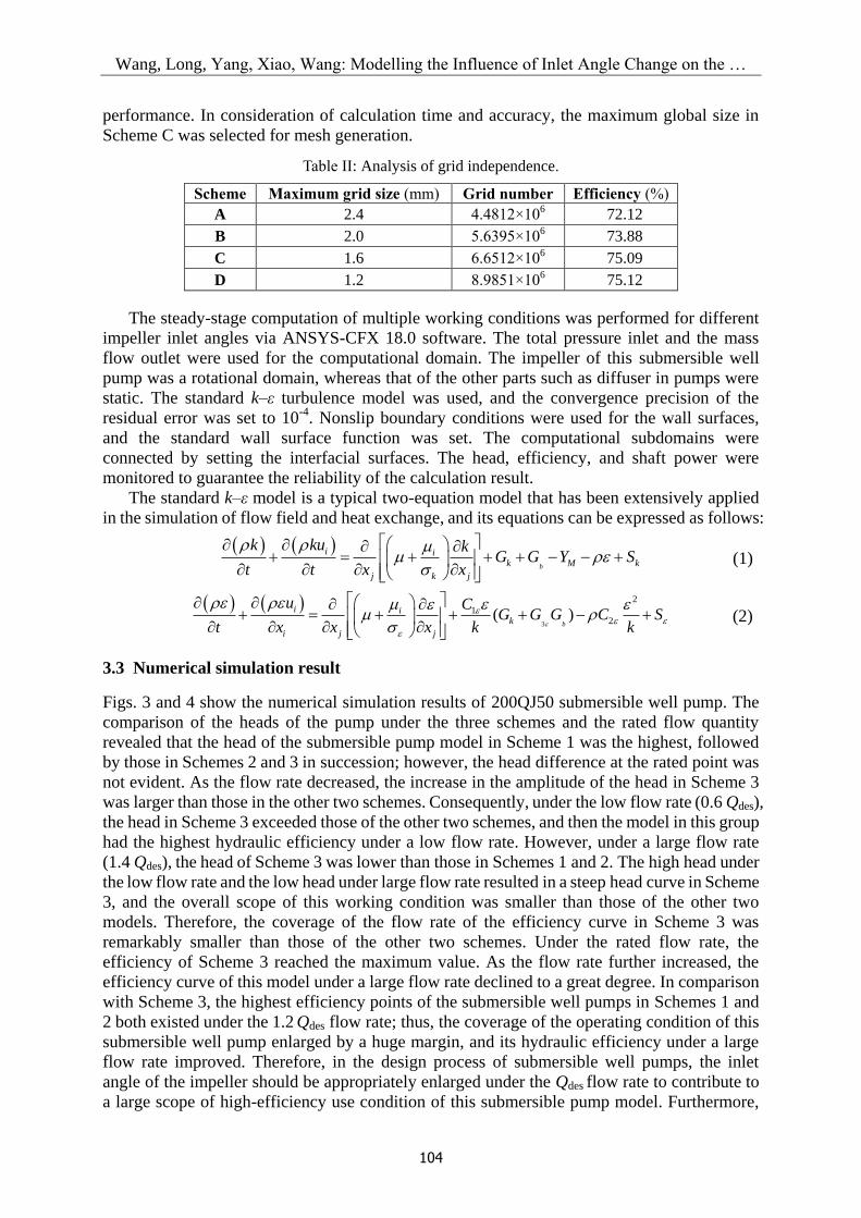
Table II shows the independence analysis results of the meshes. When the global meshes
were 1.6 mm in size, the simulation performance was approximate to the predicted
Wang, Long, Yang, Xiao, Wang: Modelling the Influence of Inlet Angle Change on the …
104
performance. In consideration of calculation time and accuracy, the maximum global size in
Scheme C was selected for mesh generation.
Table II: Analysis of grid independence.
Scheme Maximum grid size (mm) Grid number Efficiency (%)
A 2.4 4.4812×10⁶ 72.12
B 2.0 5.6395×10⁶ 73.88
C 1.6 6.6512×10⁶ 75.09
D 1.2 8.9851×10⁶ 75.12
The steady-stage computation of multiple working conditions was performed for different
impeller inlet angles via ANSYS-CFX 18.0 software. The total pressure inlet and the mass
flow outlet were used for the computational domain. The impeller of this submersible well
pump was a rotational domain, whereas that of the other parts such as diffuser in pumps were
static. The standard k–ε turbulence model was used, and the convergence precision of the
residual error was set to 10-4
. Nonslip boundary conditions were used for the wall surfaces,
and the standard wall surface function was set. The computational subdomains were
connected by setting the interfacial surfaces. The head, efficiency, and shaft power were
monitored to guarantee the reliability of the calculation result.
The standard k–ε model is a typical two-equation model that has been extensively applied
in the simulation of flow field and heat exchange, and its equations can be expressed as follows:
b
i ik M k
j k j
k ku kG G Y S
t t x x
(1)
3
2
12( )
b
i ik
i j j
u CG G G C S
t x x x k k
(2)
3.3 Numerical simulation result
Figs. 3 and 4 show the numerical simulation results of 200QJ50 submersible well pump. The
comparison of the heads of the pump under the three schemes and the rated flow quantity
revealed that the head of the submersible pump model in Scheme 1 was the highest, followed
by those in Schemes 2 and 3 in succession; however, the head difference at the rated point was
not evident. As the flow rate decreased, the increase in the amplitude of the head in Scheme 3
was larger than those in the other two schemes. Consequently, under the low flow rate (0.6 Qdes),
the head in Scheme 3 exceeded those of the other two schemes, and then the model in this group
had the highest hydraulic efficiency under a low flow rate. However, under a large flow rate
(1.4 Qdes), the head of Scheme 3 was lower than those in Schemes 1 and 2. The high head under
the low flow rate and the low head under large flow rate resulted in a steep head curve in Scheme
3, and the overall scope of this working condition was smaller than those of the other two
models. Therefore, the coverage of the flow rate of the efficiency curve in Scheme 3 was
remarkably smaller than those of the other two schemes. Under the rated flow rate, the
efficiency of Scheme 3 reached the maximum value. As the flow rate further increased, the
efficiency curve of this model under a large flow rate declined to a great degree. In comparison
with Scheme 3, the highest efficiency points of the submersible well pumps in Schemes 1 and
2 both existed under the 1.2 Qdes flow rate; thus, the coverage of the operating condition of this
submersible well pump enlarged by a huge margin, and its hydraulic efficiency under a large
flow rate improved. Therefore, in the design process of submersible well pumps, the inlet
angle of the impeller should be appropriately enlarged under the Qdes flow rate to contribute to
a large scope of high-efficiency use condition of this submersible pump model. Furthermore,

Wang, Long, Yang, Xiao, Wang: Modelling the Influence of Inlet Angle Change on the …
105
the increase in inlet angle would result in a clear shift in the extreme point on the efficiency
curve of the submersible well pump toward the operating condition with a large flow rate.
Such effect would considerably improve the efficiency of submersible well pumps under a
large flow rate and slightly improve the efficiency under a low flow rate.
0.6 0.8 1.0 1.2 1.4
63
66
69
72
75
Flow rate
case1
case2
case3
Eff
icie
ncy
η/%
0.6 0.8 1.0 1.2 1.424
27
30
33
36
39
42
case1
case2
case3
Hea
d H
/mFlow rate
Figure 3: Prediction results of submersible well Figure 4: Prediction results of submersible well
pump head for 200QJ50. pump efficiency for 200QJ50.
The comparison of the performance of Scheme 1 with that of Scheme 2 shows that the
head of Scheme 1 was slightly higher than that of Scheme 2 within the full scope of the flow
rate. Moreover, the efficiency of Scheme 1 under the low flow rate was slightly higher than
that of Scheme 2 under the rated flow rate due to the head difference. However, under a large
flow rate, if a single value was taken for the inlet angle on the basis of the calculation result,
the performance under large flow rate would certainly improve. However, the head and
efficiency under the low flow rate could not satisfy the related requirements, and the axial
power curve of the model would shift toward the large flow rate, thus weakening the non-
overload performance of the multistage pump.
4. RESULT ANALYSIS AND DISCUSSION
4.1 Flow field analysis in pump
The internal flow field distribution of the three groups of submersible well pump models
under different flow conditions was further analysed to probe into the influence mechanism of
the inlet angle on the performance of the submersible well pump and obtain the internal
medium distribution in the submersible pump under different inlet angles.
Fig. 5 shows the unfolded streamline distribution graph of the cross section in the impeller
flow channel of the three groups of submersible well pumps under the 0.6 Qdes flow rate. The
actual rate of the impeller channel was far smaller than its discharge capacity. Thus, a flow
separation phenomenon occurred near the blade back in the middle segment of the first-stage
impeller channel in the three groups of models. Under the actions of flow separation and
pressure difference, the medium flow inside the impeller channel was no longer a uniform
laminated flow, and the secondary flow of the liquid medium perpendicular to the main flow
direction appeared. The secondary flow was more evident in the impeller channel under
Schemes 2 and 3 compared with that in Scheme 1. In addition, the secondary flow in the
impeller channel caused a vortex in the latter half segment of the individual channel. This vortex
might result in a large hydraulic loss. At the secondary impeller inlet of the three groups of
models, the liquid medium maintained a certain peripheral speed after passing through the guide
blade of the previous stage; thus, its incoming flow angle was larger than the inlet angle of the
primary-stage impeller. Given the minimum inlet angle in Scheme 3, a mismatching

Wang, Long, Yang, Xiao, Wang: Modelling the Influence of Inlet Angle Change on the …
106
phenomenon occurred between the medium’s incoming flow angle and its blade inlet angle at
the inlet of the secondary impeller; that is, the fluid tended to bypass the blade inlet rim due to
the small inlet angle and then entered the side near the back face. Therefore, the secondary flow
in the impeller channel occurred in advance, and a low-voltage vortex region was induced in
the middle segment of the impeller channel. In Schemes 1 and 2, the difference between the
incoming flow angle at the inlet and that at the primary stage also induced the occurrence of
secondary flow in the channel in advance. The strength of the secondary flow was weaker
than that of Scheme 3 because the inlet angle was large. A vortex was not induced by the
secondary flow in Scheme 1. Even though a low-pressure vortex was induced in the flow
channel of Scheme 2, the intensity of the vortex core was smaller than that in Scheme 3.
Scheme 1 Scheme 2 Scheme 3
Figure 5: Streamline distribution on the cross section of the impeller channel under 0.6 Qdes.
Figs. 6 and 7 show the unfolded streamline distribution graphs of the cross section in the
impeller channel of the three groups of submersible well pump models under the Qdes and 1.4
Qdes flow rates. Under the Qdes flow rate, the liquid medium distribution in the impeller
channel improved greatly in comparison with that under a low flow rate. Moreover, its
discharge capacity had a high matching ratio with the actual discharge rate. Therefore, even
though the secondary flow caused by blade extrusion remained in the channel, the overall
flow field distribution had evident layers, which could increase the hydraulic efficiency.
Scheme 1 Scheme 2 Scheme 3
Figure 6: Streamline distribution on the cross section of the impeller channel under Qdes.
Scheme 1 Scheme 2 Scheme 3
Figure 7: Streamline distribution on the cross section of the impeller channel under1.4 Qdes.

Wang, Long, Yang, Xiao, Wang: Modelling the Influence of Inlet Angle Change on the …
107
As the flow rate increased, the actual discharge rate of the impeller exceeded the optimal
discharge rate under the 1.4 Qdes flow rate. Hence, the extruding effect of the blade on the
inlet’s incoming flow was clear, and a high flow-rate region was formed near the working face
in the first half segment of the impeller channel. Thus, the pressure on the working face of the
impeller decreased greatly, inducing flow separation at the middle segment of the impeller. In
the three groups of schemes, the inlet angle of Scheme 3 was the minimum, and the
unmatching ratio between its blade and incoming flow angles was also the highest. Thus, the
flow separation phenomenon in the last half segment of the channel was the most evident.
Figs. 8-10 show the static pressure distribution on the primary impeller blade of the three
different inlet angle schemes under different flow quantities. Under the 0.6 Qdes flow rate, a
low-pressure region was generated at the back face near the inlet rim of the impeller blade of
the submersible well pump. This region was caused by the non-uniform local speed distribution
of the liquid medium. The speed of the liquid medium at the inlet rim near the back face was
higher than that at the side of the working face because of the extruding effect of the blade inlet
rim. The static pressure distribution at this position was lower than at the other positions in the
channel. Near the low-pressure core region near the inlet at the rim, the liquid medium could
easily generate flow turbulence to diffuse inside the impeller channel. Such turbulence caused
a secondary flow in the channel and induced a vortex. In the three groups of schemes, the
coverage area of the low-pressure core region was smaller than those of other two schemes. The
low-pressure region was mainly distributed at the lower half part at the inlet rim near the rear
cover plate, and its minimum pressure was higher than those of the other schemes. In Schemes
2 and 3, the pressure gradient distribution was large in the low-pressure region, and the coverage
area was already extended to the blade inlet rim near the first half part of the front cover plate.
Meanwhile, the diffusion trend toward the impeller channel was also manifested in the low-
pressure region in Scheme 2. This result indicated that among the three groups of schemes, the
parameter of the inlet angle used in scheme 1 has a better effect on reducing the low-pressure
core region at the back face of the inlet rim. By contrast, selecting a large constant inlet angle
(Scheme 2) resulted in the diffusion phenomenon of the low-pressure region inside the channel.
Scheme 1 Scheme 2 Scheme 3
Figure 8: Static pressure distribution on the blade of the first impeller under 0.6 Qdes.
Scheme 1 Scheme 2 Scheme 3
Figure 9: Static pressure distribution on the blade of the first impeller under Qdes.
Scheme 1 Scheme 2 Scheme 3
Figure 10: Static pressure distribution on the blade of the first impeller under 1.4Qdes.
Under the Qdes flow rate, the low-pressure region still existed on the blade back face in
Scheme 2, whereas the low-pressure regions on the blade back face in Schemes 1 and 3
weakened greatly. In these regions, the pressure gradient of the low-pressure core region in
Scheme 1 was not different from that at other positions of the flow field. However, the low-
Wang, Long, Yang, Xiao, Wang: Modelling the Influence of Inlet Angle Change on the …
108
pressure core region in Scheme 3 mainly appeared at the first half segment and the last half
part of the back face of the blade inlet rim, and a core region fault with a small pressure
gradient appeared in the middle region. These occurrences manifested that the constant inlet
angle of Scheme 3 could satisfy the distribution of the incoming liquid flow at the centre of
the blade inlet rim, but its two sides did not match the angle of the incoming flow to a certain
degree. Under the 1.4 Qdes flow rate, the discharge capacity of the impeller channel was
completely released because the discharge quantity was extremely large, thus greatly
inhibiting the flow separation phenomenon caused by the non-uniform speed distribution in
the channel. Nevertheless, the high-speed region was formed because the small inlet angle
was smaller than the incoming angle that remained in the first half part of blade back face in
Scheme 3. In addition, the region’s scope was larger than those in Schemes 1 and 2. This low-
pressure region continuously diffused in the channel as the flow rate increased, consequently
increasing the hydraulic loss and hydraulic efficiency in Scheme 3.
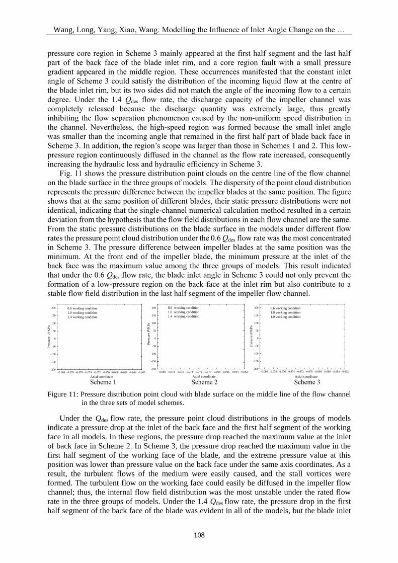
Fig. 11 shows the pressure distribution point clouds on the centre line of the flow channel
on the blade surface in the three groups of models. The dispersity of the point cloud distribution
represents the pressure difference between the impeller blades at the same position. The figure
shows that at the same position of different blades, their static pressure distributions were not
identical, indicating that the single-channel numerical calculation method resulted in a certain
deviation from the hypothesis that the flow field distributions in each flow channel are the same.
From the static pressure distributions on the blade surface in the models under different flow
rates the pressure point cloud distribution under the 0.6 Qdes flow rate was the most concentrated
in Scheme 3. The pressure difference between impeller blades at the same position was the
minimum. At the front end of the impeller blade, the minimum pressure at the inlet of the
back face was the maximum value among the three groups of models. This result indicated
that under the 0.6 Qdes flow rate, the blade inlet angle in Scheme 3 could not only prevent the
formation of a low-pressure region on the back face at the inlet rim but also contribute to a
stable flow field distribution in the last half segment of the impeller flow channel.
-0.080 -0.078 -0.076 -0.074 -0.072 -0.070 -0.068 -0.066 -0.064 -0.062-200
-150
-100
-50
0
50
100
150
200 0.6 working condition
1.0 working condition
1.4 working condition
Pre
ssu
re P
/KP
a
Axial coordinate -0.080 -0.078 -0.076 -0.074 -0.072 -0.070 -0.068 -0.066 -0.064 -0.062
-200
-150
-100
-50
0
50
100
150
200
0.6 working condition
1.0 working condition
1.4 working condition
Axial coordinate
Pre
ssure
P/K
Pa
-0.080 -0.078 -0.076 -0.074 -0.072 -0.070 -0.068 -0.066 -0.064 -0.062
-200
-150
-100
-50
0
50
100
150
200
0.6 working condition
1.0 working condition
1.0 working condition
Axial coordinate
Pre
ssure
P/K
Pa
Scheme 1 Scheme 2 Scheme 3
Figure 11: Pressure distribution point cloud with blade surface on the middle line of the flow channel
in the three sets of model schemes.
Under the Qdes flow rate, the pressure point cloud distributions in the groups of models
indicate a pressure drop at the inlet of the back face and the first half segment of the working
face in all models. In these regions, the pressure drop reached the maximum value at the inlet
of back face in Scheme 2. In Scheme 3, the pressure drop reached the maximum value in the
first half segment of the working face of the blade, and the extreme pressure value at this
position was lower than pressure value on the back face under the same axis coordinates. As a
result, the turbulent flows of the medium were easily caused, and the stall vortices were
formed. The turbulent flow on the working face could easily be diffused in the impeller flow
channel; thus, the internal flow field distribution was the most unstable under the rated flow
rate in the three groups of models. Under the 1.4 Qdes flow rate, the pressure drop in the first
half segment of the back face of the blade was evident in all of the models, but the blade inlet

Wang, Long, Yang, Xiao, Wang: Modelling the Influence of Inlet Angle Change on the …
109
angle had the highest matching ratio with the incoming flow angle of the liquid medium in
Scheme 3. Thus, the pressure drop reached the maximum value. The pressure drop reached
the minimum value at the first half segment, and a dense point cloud distribution was
observed in the middle segment of the flow channel due to the large inlet angle in Scheme 2.
This result indicated that the flow field distribution of Scheme 2 was under a steady state.
4.2 Experimental analysis of pump performance
On the basis of the numerical prediction results, a performance test was conducted on the
200QJ50 submersible well pump. Scheme 1 was selected for the prototype manufacturing and
performance testing in consideration of the strict performance requirements of the cooperative
enterprise for submersible well pumps under a large flow rate.
In the test process of the submersible well pump, a six-stage structure was used for the
pump to match the existing motor of specific power. Therefore, the prediction results obtained
from the numerical calculation were converted into a six-stage performance. Fig. 12 displays
the comparison of the numerical prediction and experimental measurement results of the
performance of the 200QJ50 submersible well pump.
The predicted and test values of the head of the 200QJ50 submersible well pump at rated
flow rates were identical, with an error of approximately 1%. However, the prediction of shaft
power through numerical calculation had a certain error, and the predicted shaft power was
lower than the test shaft power by 2.6 %. Consequently, under a small deviation in the predicted
head value, the prediction efficiency was higher than the test efficiency by 2.3% because the
axial length of the pump increased with the stage number. Thus, the mechanical losses, such
as the sealing and filler losses, result in a certain structural deviation in numerical prediction.
The test indicated that the single-stage head of the 200QJ50 submersible well pump was
higher than the design requirement, and its efficiency exceeded the national standard
requirement.
0 10 20 30 40 50 60 70 800
20
40
60
80
100
120
140
Test head
Numerical head
Hea
d H
/m
Flow rate Q/(m3·h-1)
0
10
20
30
40
50
60
70
80
90
Test efficiency
Numerical efficiency
Eff
icie
ncy
η/%
0
10
20
30
Test Shaft power
Numerical Shaft power
Sh
aft
po
wer
P/k
W
Figure 12: Comparisons between the test and numerical results of the 200QJ50 submersible well pump.
5. CONCLUSION
Three different inlet angle schemes were designed to improve the hydraulic design of
submersible well pumps and explore the influence mechanism of the change in impeller inlet
angle on the performance of submersible well pumps. On the basis of the numerical
simulation results, the internal flow characteristics of the three schemes under different
working conditions were analysed, and the optimal scheme was verified through experimental
comparison. The following conclusions were drawn:

Wang, Long, Yang, Xiao, Wang: Modelling the Influence of Inlet Angle Change on the …
110
1) The matching ratio between the blade inlet and incoming flow angles of a fluid is an
important factor that influences the performance of submersible well pumps. The design
process should emphasize on enlarging the inlet angle but should optimize the parameters
instead by following the flow field law.
2) The discharge capacity is consistent with the physical truth under rated flow rates; thus,
the improvement of the flow field by the inlet angle is not evident; however, improvement is
observable under partial working conditions. Therefore, enlarging the inlet angle can weaken
the low-pressure vortex at the inlet and reduce the turbulence of the flow field.
3) In comparison with the hydraulic performance of the pump under the constant inlet
angle scheme, that under Scheme 1 (i.e., uniform change of the inlet angle from the front
cover plate to the rear cover plate) considerably improved. This result provides a reference for
the further development of a follow-up hydraulic design of submersible well pumps.
Numerical simulation was combined with experimental research in this study.
Furthermore, a calculation model for the hydraulic analysis of submersible well pumps was
proposed. Blade inlet angle, which is an important factor that influences the efficiency of
impeller design, was also investigated. This study could guide the optimization of the
hydraulic design of submersible well pumps. Only three different schemes were designed in
this study; therefore, an optimization analysis method must be considered in the follow-up
optimization design of submersible well pumps.
ACKNOWLEDGEMENT
The study was supported by the Changzhou Sci&Tech Program (No. CJ20190048) and the Jiangsu
Province Graduate Practice Innovation Project (No. SJCX18_0743).
REFERENCES
[1] Bianchini, A.; Rossi, J.; Antipodi, L. (2018). A procedure for condition-based maintenance and
diagnostics of submersible well pumps through vibration monitoring, International Journal of
System Assurance Engineering and Management, Vol. 9, No. 5, 999-1013, doi:10.1007/s13198-
018-0711-3
[2] Sardjono, P.; Saputra, M. N. W. (2016). Optimal bottomhole pressure control on oil well
production using PID-linear hybrid control on electric submersible pump, 2016 8th International
Conference on Information Technology and Electrical Engineering, 6 pages
[3] Shankar, V. K. A.; Umashankar, S.; Paramasivam, S.; Hanigovszki, N. (2016). A comprehensive
review on energy efficiency enhancement initiatives in centrifugal pumping system, Applied
Energy, Vol. 181, 495-513 , doi:10.1016/j.apenergy.2016.08.070
[4] Farid Ayad, A.; Abdalla, H. M.; El-Azm Aly, A. A. (2015). Effect of semi-open impeller side
clearance on the centrifugal pump performance using CFD, Aerospace Science and Technology,
Vol. 47, 247-255, doi:10.1016/j.ast.2015.09.033
[5] Guo, X.; Zhu, Z.; Cui, B.; Shi, G. (2016). Effects of the number of inducer blades on the anti-
cavitation characteristics and external performance of a centrifugal pump, Journal of Mechanical
Science and Technology, Vol. 30, No. 7, 3173-3181, doi:10.1007/s12206-016-0510-1
[6] Wang, C.; Chen, X.; Qiu, N.; Zhu, Y.; Shi, W. (2018). Numerical and experimental study on the
pressure fluctuation, vibration, and noise of multistage pump with radial diffuser, Journal of the
Brazilian Society of Mechanical Sciences and Engineering, Vol. 40, No. 10, Paper 481,
doi:10.1007/s40430-018-1355-6
[7] Zhou, F.-M.; Wang, X.-F. (2016). Effects of staggered blades on the hydraulic characteristics of a
1400-MW canned nuclear coolant pump, Advances in Mechanical Engineering, Vol. 8, No. 8, 21
pages, doi:10.1177/1687814016657944
[8] Khoeini, D.; Shirani, E. (2018). Enhancement of a centrifugal pump performance by
simultaneous use of splitter blades and angular impeller diffuser, International Journal of Fluid
Machinery and Systems, Vol. 11, No. 2, 191-204, doi:10.5293/IJFMS.2018.11.2.191

Wang, Long, Yang, Xiao, Wang: Modelling the Influence of Inlet Angle Change on the …
111
[9] Bacharoudis, E. C.; Filios, A. E.; Mentzos, M. D.; Margaris, D. P. (2008). Parametric study of a
centrifugal pump impeller by varying the outlet blade angle, The Open Mechanical Engineering
Journal, Vol. 2, 75-83, doi:10.2174/1874155X00802010075
[10] Nishi, Y.; Fukutomi, J. (2015). Component analysis of unsteady hydrodynamic force of closed-
type centrifugal pump with single blades of different blade outlet angles, International Journal of
Rotating Machinery, Vol. 2015, Paper 419736, 17 pages, doi:10.1155/2015/419736
[11] Lee, S. H.; Lee, D. R. (2016). Flow analysis of the impeller with different inlet angles in the
centrifugal pump, Journal of Computational Fluids Engineering, Vol. 21, No. 1, 58-63,
doi:10.6112/kscfe.2016.21.1.058
[12] Rakibuzzaman, M.; Kim, K.; Kim, H.-H.; Suh, S.-H. (2017). Energy saving rates for a multistage
centrifugal pump with variable speed drive, Journal of Power Technologies, Vol. 97, No. 2, 163-
168
[13] Cheng, X.; Lü, B.; Zhang, X.; Wei, Y.; Zhang, S.; Wang, P. (2018). Influence of outlet edge position
of guide vane on performance of well submersible pump, Transactions of the Chinese Society of
Agricultural Engineering, Vol. 34, No. 10, 68-75, doi:10.11975/j.issn.1002-6819.2018.10.008
[14] Shi, W.; Zhou, L.; Lu, W.; Xu, L.; Li, W. (2013). Numerical simulation and experimental study
of different stages deep-well centrifugal pump, Journal of Computational & Theoretical
Nanoscience, Vol. 10, No. 12, 2897-2901, doi:10.1166/jctn.2013.3297
[15] Wang, H.; Shi, W.; Yang, Y.; Zhou, L.; Lu, W. (2018). Matching number of blades between
impeller and diffuser blade effect on performance of well submersible centrifugal pump,
Transactions of the Chinese Society for Agricultural Machinery, Vol. 49, No. 7, 103-111,
doi:10.6041/j.issn.1000-1298.2018.07.013
[16] Stel, H.; Sirino, T.; Ponce, F. J.; Chiva, S.; Morales, R. E. M. (2015). Numerical investigation of
the flow in a multistage electric submersible pump, Journal of Petroleum Science and
Engineering, Vol. 136, 41-54, doi:10.1016/j.petrol.2015.10.038
[17] El-Gazzar, D. M. S.; Hawash, S. A.-A. F. (2018). Optimizing centrifugal pump performance by
different blade configuration patterns, American Journal of Mechanical and Industrial
Engineering, Vol. 3, No. 1, 1-14, doi:10.11648/j.ajmie.20180301.11
[18] Gölcü, M.; Pancar, Y.; Sekmen, Y. (2006). Energy saving in a deep well pump with splitter blade,
Energy Conversion and Management, Vol. 47, No. 5, 638-651, doi:10.1016/
j.enconman.2005.05.001
[19] Wei, Q.; Sun, X. (2017).Performance influence in submersible pump with different diffuser inlet
widths, Advances in Mechanical Engineering, Vol. 9, No. 1, 8 pages, doi:10.1177/
1687814016683354
[20] Ajay, A. J.; Stephen, S. E. A.; Smart, D. S. R. (2017). Shape optimization of submersible pump
impeller design, International Conference on Recent Advances in Aerospace Engineering, 6 pages
[21] Lu, Z.; He, X.; Wang, C. (2018). Influencing factors of self-priming time of multistage self-
priming centrifugal pump, DYNA, Vol. 93, No. 6, 630-635, doi:10.6036/8930
[22] Zhou, L.; Shi, W.; Wu, S. (2013). Performance optimization in a centrifugal pump impeller by
orthogonal experiment and numerical simulation, Advances in Mechanical Engineering, Vol. 5,
Paper 385809, 7 pages, doi:10.1155/2013/385809
[23] Kim, J.-H.; Lee, H.-C.; Kim, J.-H.; Kim, S.; Yoon, J.-Y.; Choi, Y.-S. (2015). Design techniques
to improve the performance of a centrifugal pump using CFD, Journal of Mechanical Science
and Technology, Vol. 29, No. 1, 215-225, doi:10.1007/s12206-014-1228-6
[24] Li, W.; Zhou, L.; Shi, W.; Ji, L.; Yang, Y.; Zhao, X. (2017). PIV experiment of the unsteady flow
field in mixed-flow pump under part loading condition, Experimental Thermal and Fluid Science,
Vol. 83, 191-199, doi:10.1016/j.expthermflusci.2017.01.009
[25] Capurso, T.; Bergamini, L.; Torresi, M. (2019). Design and CFD performance analysis of a novel
impeller for double suction centrifugal pumps, Nuclear Engineering and Design, Vol. 341, 155-
166, doi:10.1016/j.nucengdes.2018.11.002
[26] Jiang, X.; Wang, C.; Wu, J.; Shi, W.; Liu, S.; Yang, Y. (2017). Effect of diffuser inlet width on
cantilever multistage centrifugal pump, DYNA, Vol. 92, No. 1, 63-70, doi:10.6036/8153
[27] Namazizadeh, M.; Gevari, M. T.; Mojaddam, M.; Vajdi, M. (2020). Optimization of the splitter
blade configuration and geometry of a centrifugal pump impeller using design of experiment,
Journal of Applied Fluid Mechanics, Vol. 13, No. 1, 89-101, doi:10.29252/jafm.13.01.29856