Embed Size (px)
Citation preview
8/7/2019 modelo dianamico de induccion lineal
http://slidepdf.com/reader/full/modelo-dianamico-de-induccion-lineal 1/5
ISSN 1392 – 124X INFORMATION TECHNOLOGY AND CONTROL, 2005, Vol.34, No.1
DYNAMIC MODELS OF LINEAR INDUCTION DRIVE
R. Rinkevičienė, A. Petrovas
Vilnius Gediminas Technical University
Abstract. Due to open magnetic circuit and limited length of the linear induction motor inductor phase currents arenot equal. The article deals with model of linear induction drive taking into account magnetic asymmetry of linear
induction motor at different connection of windings. Developed models are presented and results of simulation areconsidered.
1. Indroduction 2. Mathematical model of a motor with Y
connected windings with neutral wireLinear electric motor (LIM) technology has been
broadly used in the aspects of traffic, industry, infor-mation, automation, material transportation, elevatorsand postal mechanical systems [1, 2, 3].
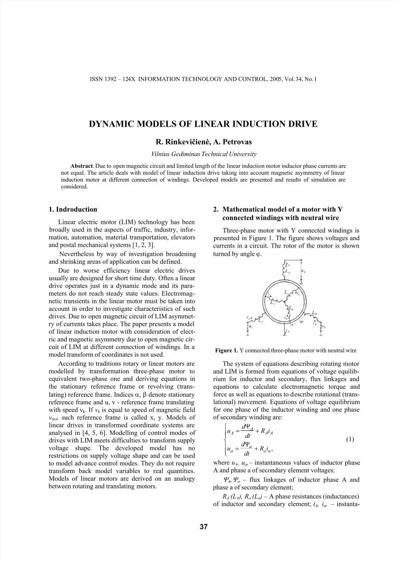
Three-phase motor with Y connected windings is presented in Figure 1. The figure shows voltages andcurrents in a circuit. The rotor of the motor is shown
turned by angle ϕ. Nevertheless by way of investigation broadeningand shrinking areas of application can be defined.
Due to worse efficiency linear electric drivesusually are designed for short time duty. Often a linear drive operates just in a dynamic mode and its para-
meters do not reach steady state values. Electromag-netic transients in the linear motor must be taken intoaccount in order to investigate characteristics of suchdrives. Due to open magnetic circuit of LIM asymmet-ry of currents takes place. The paper presents a modelof linear induction motor with consideration of elect-
ric and magnetic asymmetry due to open magnetic cir-cuit of LIM at different connection of windings. In amodel transform of coordinates is not used.
Figure 1. Y connected three-phase motor with neutral wire
According to traditions rotary or linear motors aremodelled by transformation three-phase motor toequivalent two-phase one and deriving equations in
the stationary reference frame or revolving (trans-
lating) reference frame. Indices α, β denote stationaryreference frame and u, v - reference frame translatingwith speed vk . If vk is equal to speed of magnetic fieldv0el , such reference frame is called x, y. Models of linear drives in transformed coordinate systems are
analysed in [4, 5, 6]. Modelling of control modes of drives with LIM meets difficulties to transform supply
voltage shape. The developed model has norestrictions on supply voltage shape and can be usedto model advance control modes. They do not requiretransform back model variables to real quantities.Models of linear motors are derived on an analogy between rotating and translating motors.
The system of equations describing rotating motor and LIM is formed from equations of voltage equilib-rium for inductor and secondary, flux linkages andequations to calculate electromagnetic torque and
force as well as equations to describe rotational (trans-lational) movement. Equations of voltage equilibriumfor one phase of the inductor winding and one phaseof secondary winding are:
+Ψ
=
+Ψ
=
,aaa
a
A A A
A
i Rdt
d u
i Rdt
d u
(1)
where u A , ua , – instantaneous values of inductor phaseA and phase a of secondary element voltages;
Ψ A ,Ψ a – flux linkages of inductor phase A and phase a of secondary element;
R A (L A ), Ra (La ) – A phase resistances (inductances)of inductor and secondary element; i A , ia , – instanta-
37
8/7/2019 modelo dianamico de induccion lineal
http://slidepdf.com/reader/full/modelo-dianamico-de-induccion-lineal 2/5
R. Rinkevičienė, A. Petrovas
neous values of inductor phase A winding and phase asecondary element currents.
Phase A flux linkage of a stator and rotor is:
( )( ) ( )[
( )( ) ([
°++°−+++++=Ψ
°−+°++
++++=Ψ
,120cos120coscos
120cos120cos
cos
ϕ ϕ ϕ
ϕ ϕ
ϕ
C B ASR
cb Raaa
cbSR
aSRC BS A A A
iiiM
iiM i L
iiM
iM iiM i L
]
)]
))]
(2)
where M SR – mutual inductance between inductor and
rotor (secondary element) when the axes of coilscoincide [H]; M S ,(M R ) – mutual inductance between
different coils of inductor (rotor or secondary) in H; ϕ - angle between rotor and inductor coils in electricdegrees.
Electromagnetic torque developed by rotatingmotor is [6, 7]:
( )[ ]
( ) ([ ]( ) ([ .120sin
120sin
sin
°−++−
−°+++−
−++−=
ϕ
ϕ
ϕ
bC a Bc ASR
aC c Bb ASR
cC b Ba ASRem
iiiiii pM
iiiiii pM
iiiiii pM M
(3)
On a base of power equivalency in rotating andtranslating motors an expression to calculate the forcedeveloped by LIM is obtained:
, p
M F em
em ⋅=τ
π (4)
, x⋅=τ
π ϕ (5)
whereτ is pole pitch; p is the number of pole pairs, x-
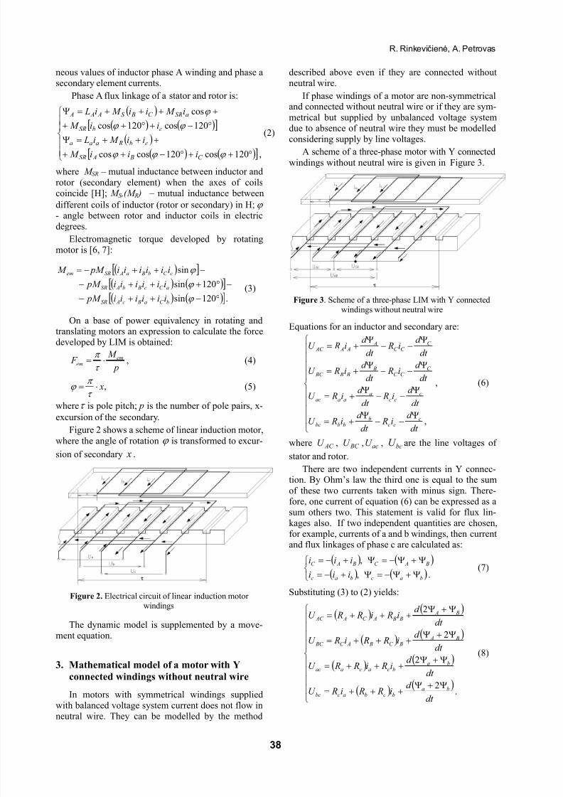
excursion of the secondary.Figure 2 shows a scheme of linear induction motor,
where the angle of rotation ϕ is transformed to excur-
sion of secondary x .
Figure 2. Electrical circuit of linear induction motor windings
The dynamic model is supplemented by a move-ment equation.
3. Mathematical model of a motor with Y
connected windings without neutral wire
In motors with symmetrical windings suppliedwith balanced voltage system current does not flow inneutral wire. They can be modelled by the method
described above even if they are connected withoutneutral wire.
If phase windings of a motor are non-symmetricaland connected without neutral wire or if they are sym-
metrical but supplied by unbalanced voltage systemdue to absence of neutral wire they must be modelled
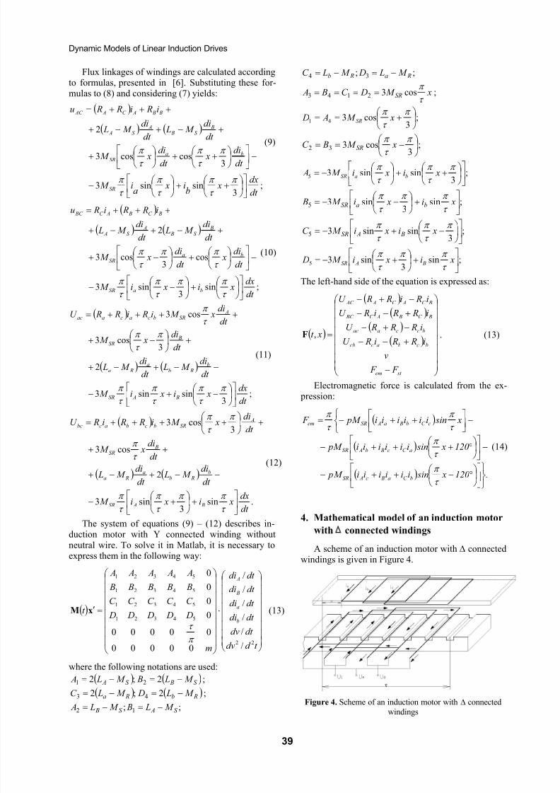
considering supply by line voltages.A scheme of a three-phase motor with Y connected
windings without neutral wire is given in Figure 3.
Figure 3. Scheme of a three-phase LIM with Y connectedwindings without neutral wire
Equations for an inductor and secondary are:
Ψ−−Ψ+=
Ψ−−
Ψ+=
Ψ−−
Ψ+=
Ψ−−
Ψ+=
,dt
d i Rdt
d i RU
dt
d i R
dt
d i RU
dt
d i R
dt
d i RU
dt
d i R
dt
d i RU
ccc
bbbbc
ccc
aaaac
C C C
B B B BC
C C C
A A A AC
, (6)
where , ,U , are the line voltages of
stator and rotor.
AC U BC U ac bcU
There are two independent currents in Y connec-tion. By Ohm’s law the third one is equal to the sum
of these two currents taken with minus sign. There-fore, one current of equation (6) can be expressed as asum others two. This statement is valid for flux lin-kages also. If two independent quantities are chosen,for example, currents of a and b windings, then currentand flux linkages of phase c are calculated as:
( ) ( )( ) ( )
Ψ+Ψ−=Ψ+−=
Ψ+Ψ−=Ψ+−=.,
,
bacbac
B AC B AC
iii
iii(7)
Substituting (3) to (2) yields:
( )( )
( )( )
( )( )
( )( )
Ψ+Ψ+++=
Ψ+Ψ+++=
Ψ+Ψ+++=
Ψ+Ψ+++=
.2
2
2
2
dt
d i R Ri RU
dt
d i Ri R RU
dt
d i R Ri RU
dt
d i Ri R RU
babcbacbc
babcacaac
B A BC B AC BC
B A B B AC A AC
(8)
38
8/7/2019 modelo dianamico de induccion lineal
http://slidepdf.com/reader/full/modelo-dianamico-de-induccion-lineal 3/5
Dynamic Models of Linear Induction Drives
Flux linkages of windings are calculated accordingto formulas, presented in [6]. Substituting these for-mulas to (8) and considering (7) yields:
;; 34 Ra Rb M L DM LC −=−=
xM DC B A SRτ
π cos32143 ==== ;
( )
( ) ( )
;3
sinsin3
3coscos3
2
dt
dx x
bi x
aiM
dt
di x
dt
di xM
dt
diM L
dt
diM L
i Ri R Ru
SR
baSR
BS B
AS A
B B AC A AC
++
−
−
++
+
+−+−+
+++=
π
τ
π
τ
π
τ
π
π
τ
π
τ
π (9)
;3
cos341
+==π
τ
π xM A D SR
;3
cos332
−== π τ π xM BC SR
;3
sinsin35
++
−=π
τ
π
τ
π xi xiM A baSR
;sin3
sin35
+
−−= xi xiM B baSRτ
π π
τ
π
( )
( ) ( )
;sin3
sin3
cos3
cos3
2
dt
dx xi xiM
dt
di x
dt
di xM
dt
diM L
dt
diM L
i R Ri Ru
baSR
baSR
BS B
AS A
BC B AC BC
+
−−
−
+
−+
+−+−+
+++=
τ
π π
τ
π
τ
π
τ
π π
τ
π (10)
;3
sinsin35
−+−=π
τ
π
τ
π xi xiM C B ASR
;sin3
sin35
+
+−= xi xiM D B ASRτ
π π
τ
π
The left-hand side of the equation is expressed as:
( )
( )( )
( )( )
−
+−−
−+−
+−−
−+−
=
st em
bcbaccb
bccaac
BC B AC BC
BC AC A AC
F F
v
i R Ri RU
i R R RU
i R Ri RU
i Ri R RU
xt ,F . (13)
( )
( ) ( )
;3
sinsin3
2
3cos3
cos3
dt
dx xi xiM
dt
diM L
dt
diM L
dt
di xM
dt
di xM i Ri R RU
B ASR
b Rb
a Ra
BSR
ASRbcacaac
−+−
−−+−+
+
−+
++++=
π
τ
π
τ
π
τ
π
π
τ
π
τ
π
(11)
Electromagnetic force is calculated from the ex- pression:
( )
( )
( ) .120 x siniiiiiiM p
120 x siniiiiii pM
x siniiiiii pM F
bC a Bc ASR
aC c Bb ASR
cC b Ba ASRem
°−++−
−
°+++−
−
++−=
τ
π
τ
π
τ π
τ π
(14)
( )
( ) ( )
.sin3
sin3
2
cos3
3cos3
dt
dx xi xiM
dt
diM L
dt
diM L
dt
di xM
dt di xM i R Ri RU
B ASR
b Rb
a Ra
BSR
ASRbcbacbc
+
+−
−−+−+
++
+
++++=
τ
π π
τ
π
τ
π
τ
π
π τ π
(12)
4. Mathematical model of an induction motor
with ∆ connected windingsThe system of equations (9) – (12) describes in-
duction motor with Y connected winding withoutneutral wire. To solve it in Matlab, it is necessary to
express them in the following way:A scheme of an induction motor with ∆ connected
windings is given in Figure 4.
( )
⋅
=′
t d dv
dt dv
dt di
dt di
dt di
dt di
m
D D D D D
C C C C C
B B B B B
A A A A A
t b
a
B
A
22
54321
54321
54321
54321
/
/
/
/
/
/
00000
00000
0
0
0
0
π
τ
xM (13)
where the following notations are used:
( ) ( S BS A M L BM L A −=−= 2;2 21 )
)
;
( ) ( Rb Ra M L DM LC −=−= 2;2 43 ; Figure 4. Scheme of an induction motor with ∆ connected
windings;; 12 S AS B M L BM L A −=−=
39
8/7/2019 modelo dianamico de induccion lineal
http://slidepdf.com/reader/full/modelo-dianamico-de-induccion-lineal 4/5
R. Rinkevičienė, A. Petrovas
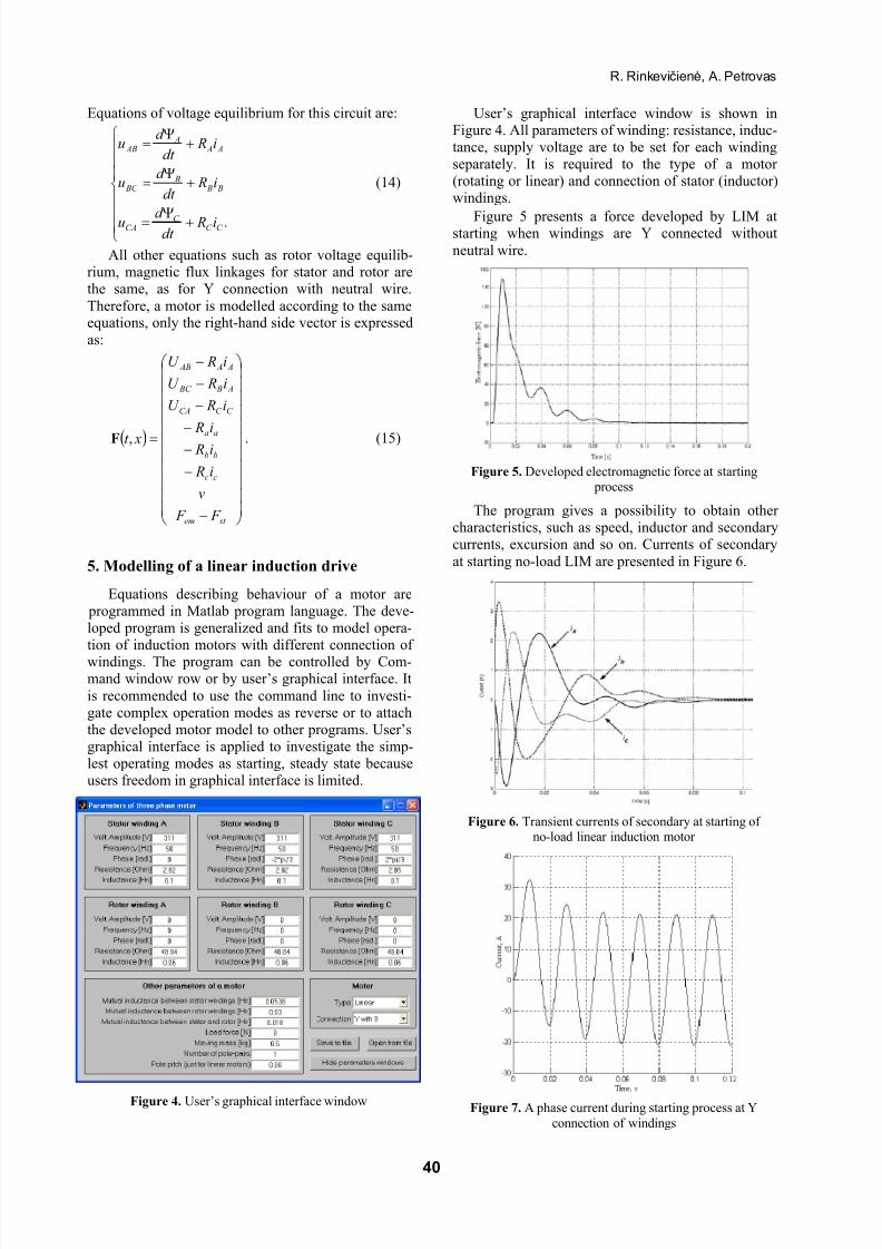
Equations of voltage equilibrium for this circuit are: User’s graphical interface window is shown inFigure 4. All parameters of winding: resistance, induc-tance, supply voltage are to be set for each windingseparately. It is required to the type of a motor (rotating or linear) and connection of stator (inductor)windings.
+Ψ=
+Ψ
=
+Ψ
=
.C C C
CA
B B B
BC
A A A
AB
i Rdt
d u
i Rdt
d u
i Rdt
d u
(14)
Figure 5 presents a force developed by LIM atstarting when windings are Y connected without
neutral wire.All other equations such as rotor voltage equilib-rium, magnetic flux linkages for stator and rotor arethe same, as for Y connection with neutral wire.
Therefore, a motor is modelled according to the sameequations, only the right-hand side vector is expressed
as:
( )
−
−
−
−
−
−
−
=
st em
cc
bb
aa
C C CA
A B BC
A A AB
F F
v
i R
i R
i R
i RU
i RU
i RU
xt ,F . (15)
Figure 5. Developed electromagnetic force at starting process
The program gives a possibility to obtain other characteristics, such as speed, inductor and secondarycurrents, excursion and so on. Currents of secondary
at starting no-load LIM are presented in Figure 6.5. Modelling of a linear induction drive
Equations describing behaviour of a motor are programmed in Matlab program language. The deve-loped program is generalized and fits to model opera-tion of induction motors with different connection of
windings. The program can be controlled by Com-mand window row or by user’s graphical interface. It
is recommended to use the command line to investi-gate complex operation modes as reverse or to attachthe developed motor model to other programs. User’sgraphical interface is applied to investigate the simp-lest operating modes as starting, steady state becauseusers freedom in graphical interface is limited.
Figure 6. Transient currents of secondary at starting of no-load linear induction motor
Figure 4. User’s graphical interface windowFigure 7. A phase current during starting process at Y
connection of windings
40

8/7/2019 modelo dianamico de induccion lineal
http://slidepdf.com/reader/full/modelo-dianamico-de-induccion-lineal 5/5
Dynamic Models of Linear Induction Drives
All data of simulation are obtained in commandline, therefore they can be easy processed and used in
new calculations.
6. Conclusions
1. The developed model of linear induction motor considers electric and magnetic asymmetry of LIM due to open magnetic circuit of LIM.
2. The developed algorithm and programs give a possibility to investigate transients in the driveswith rotating and translating motors atsymmetrical and asymmetrical supply voltages,different phase angles between them and differentmodes of winding connection.
3. Created program gives a possibility to investigatetransients of three phase linear drive withconsideration of asymmetry of LIM windings.
4. Due to absence transform of coordinates thedeveloped model facilitates investigation of LIM
control modes.
References
[1] P.-K. Budig. The Application of Linear motors. The
third International Power Electronics and motionControl conference 2000, Vol .3, 1336-1341.
[2] I. Boldea. Linear Electromagnetic actuators and their control. Proceedings of 10th International power
electronics and motion control Conference. Cavtat & Dubrovnik , 2002, 12-20.
[3] J.F. Gieras, P.D. Hartzenberg, I.J. Magura, M.Wing. Control of an elevator drive with a single-sided
linear induction motor. Fifth European Conference on
Power Electronics and Applications, 1993, Vol .4,353-358.
[4] A. Poška, R. Rinkevičienė, Č. Teišerskas. Tiesia-eigės asinchroninės pavaros skaitmeniniai dinaminiai
modeliai. Elektronika ir elektrotechnika. ISSN 1392-1215, Kaunas: Technologija, 1997, Nr .1(10), 50-54.
[5] A. Poška, R. Rinkevičienė, Č. Teišerskas. Tiesiaei-
gės elektros pavaros impulsinis valdymas. Elektro-
technika: Mokslo darbai, Kaunas: Technologija, 1997,
t . 21(30), 137-140.
[6] R. Rinkevičienė, S. Lisauskas. Tiesiaeigių mechatro-ninių sistemų modeliai. Elektronika ir elektrotechnika. Kaunas: Technologija. 2003, Nr .4(46), 69–73.
[7] R. Rinkevičienė, A. Petrovas. Tiesiaeigės asinchro-ninės pavaros modelis. Elektronika ir elektrotechnika. Kaunas: Technologija. 2004, Nr .1(50), 28–32.
[8] R. Rinkevičienė, A. Petrovas. New model of linear
induction drive. Elektronika ir elektrotechnika.
Kaunas: Technologija. 2004, Nr .2(51), 25–28.
![Induccion a MATLAB´ Algebra Lineal...Induccion a MATLAB (´ Algebra Lineal)´ Escuela de Matem´aticas Universidad Nacional 4 / 1 Ingresando vectores Alt + 91 = [ Alt + 93 = ] Alt](https://img.pdfslide.net/doc/110x75/601a3a7bbb044460fe2b95fa/induccion-a-matlab-algebra-lineal-induccion-a-matlab-algebra-lineal.jpg)