Embed Size (px)
Citation preview
MODELS
Remote Control Motorcycle Alarm System Installation & Operation Instructions
Sistema de Alarma de Motocicleta de Control Remoto Instrucciones de Instalación y Operación
Syetéme D’alarme Délécommande pour Motocyclettes Instructions D’installation et de Fonctionnement
© 2010 Gorilla Automotive
8007 Gorilla Cycle Alarm
8017 Gorilla Cycle Alarm
with 2-way pager system1018
2-way pager system
2
The Alarm Instructionsare broken into 2 sections
Section 1Covers the Gorilla Cycle Alarm
Part # 8007/8017
Section 2Covers the Gorilla
2-way pager systemPart # 8017/1018
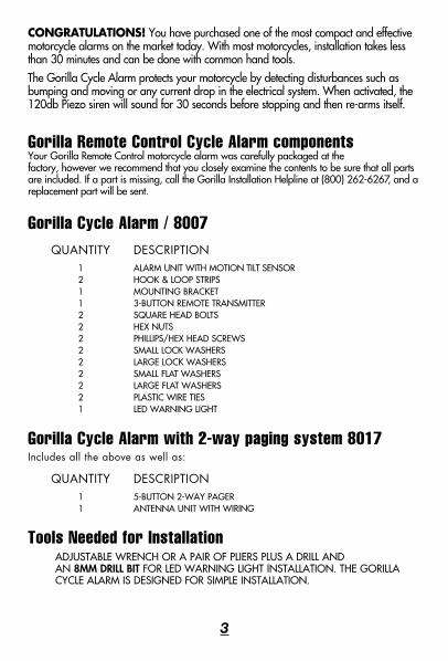
CONGRATULATIONS! You have purchased one of the most compact and effective motorcycle alarms on the market today. With most motorcycles, installation takes less than 30 minutes and can be done with common hand tools.The Gorilla Cycle Alarm protects your motorcycle by detecting disturbances such as bumping and moving or any current drop in the electrical system. When activated, the 120db Piezo siren will sound for 30 seconds before stopping and then re-arms itself.
Gorilla Remote Control Cycle Alarm componentsYour Gorilla Remote Control motorcycle alarm was carefully packaged at thefactory, however we recommend that you closely examine the contents to be sure that all parts are included. If a part is missing, call the Gorilla Installation Helpline at (800) 262-6267, and a replacement part will be sent.
Gorilla Cycle Alarm / 8007 QUANTITY DESCRIPTION 1 ALARM UNIT WITH MOTION TILT SENSOR 2 HOOK & LOOP STRIPS 1 MOUNTING BRACKET 1 3-BUTTON REMOTE TRANSMITTER 2 SQUARE HEAD BOLTS 2 HEX NUTS 2 PHILLIPS/HEX HEAD SCREWS 2 SMALL LOCK WASHERS 2 LARGE LOCK WASHERS 2 SMALL FLAT WASHERS 2 LARGE FLAT WASHERS 2 PLASTIC WIRE TIES 1 LED WARNING LIGHT
Gorilla Cycle Alarm with 2-way paging system 8017 Includes all the above as well as: QUANTITY DESCRIPTION 1 5-BUTTON 2-WAY PAGER 1 ANTENNA UNIT WITH WIRING
Tools Needed for Installation ADJUSTABLE WRENCH OR A PAIR OF PLIERS PLUS A DRILL AND
AN 8MM DRILL BIT FOR LED WARNING LIGHT INSTALLATION. THE GORILLA CYCLE ALARM IS DESIGNED FOR SIMPLE INSTALLATION.
3
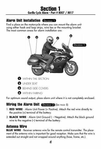
Alarm Unit Installation Diagram 1 Find a place on the motorcycle where you can mount the alarm unitusing either hook and loop strips, wire ties or the mounting bracket.The most common areas for alarm installation are:
WITHINTAILSECTION
UNDERSEAT
BEHINDSIDECOVERS
WITHINFAIRING
For optimum sound output, place alarm unit where it is not completely enclosed.
Wiring the Alarm Unit Diagram 2 (See page 5)
1. RED WIRE - Alarm Unit Power (+ Positive). Attach the red wire directly to the positive (+) terminal of the battery.
2. BLACK WIRE - Alarm Unit Ground ( – Negative). Attach the black ground wire to the negative (–) terminal of the battery.
Antenna WireBLUE WIRE - Receiver antenna wire for the remote control transmitter. The place-ment of the antenna wire is important for good reception. Make sure that the wire is extended out straight and not wrapped around anything (hose, frame, etc.).
1
2
3
4
4
1 2 34
Diagram 1
Section 1Gorilla Cycle Alarm - Part # 8007 / 8017
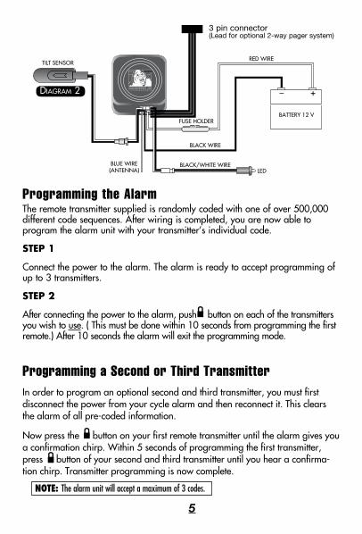
Programming the AlarmThe remote transmitter supplied is randomly coded with one of over 500,000 different code sequences. After wiring is completed, you are now able to program the alarm unit with your transmitter’s individual code.
STEP 1
Connect the power to the alarm. The alarm is ready to accept programming of up to 3 transmitters.
STEP 2
After connecting the power to the alarm, push button on each of the transmitters you wish to use. ( This must be done within 10 seconds from programming the first remote.) After 10 seconds the alarm will exit the programming mode.
Programming a Second or Third TransmitterIn order to program an optional second and third transmitter, you must first disconnect the power from your cycle alarm and then reconnect it. This clears the alarm of all pre-coded information.
Now press the button on your first remote transmitter until the alarm gives you a confirmation chirp. Within 5 seconds of programming the first transmitter, press button of your second and third transmitter until you hear a confirma-tion chirp. Transmitter programming is now complete.
_ +
5
3 pin connector(Lead for optional 2-way pager system)
NOTE: The alarm unit will accept a maximum of 3 codes.
Diagram 2
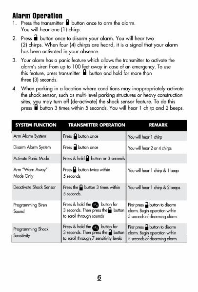
Alarm Operation1. Press the transmitter button once to arm the alarm. You will hear one (1) chirp.
2. Press button once to disarm your alarm. You will hear two (2) chirps. When four (4) chirps are heard, it is a signal that your alarm has been activated in your absence.
3. Your alarm has a panic feature which allows the transmitter to activate the alarm’s siren from up to 100 feet away in case of an emergency. To use this feature, press transmitter button and hold for more than three (3) seconds.
4. When parking in a location where conditions may inappropriately activate the shock sensor, such as multi-level parking structures or heavy construction sites, you may turn off (de-activate) the shock sensor feature. To do this press button 3 times within 5 seconds. You will hear 1 chirp and 2 beeps.
6
Arm Alarm System
Disarm Alarm System
Activate Panic Mode
Arm “Warn Away” Mode Only
Deactivate Shock Sensor
Programming Siren Sound
Programming Shock Sensitivity
You will hear 1 chirp
You will hear 2 or 4 chirps
You will hear 1 chirp & 1 beep
You will hear 1 chirp & 2 beeps
First press button to disarm alarm. Begin operation within 5 seconds of disarming alarm
First press button to disarm alarm. Begin operation within 5 seconds of disarming alarm
Press button once
Press button once
Press & hold button or 3 seconds
Press button twice within 5 seconds
Press the button 3 times within 5 seconds.
Press & hold the button for 3 seconds. Then press the button to scroll through sounds
Press & hold the button for 3 seconds. Then press the button to scroll through 7 sensitivity levels
SYSTEM FUNCTION TRANSMITTER OPERATION REMARK
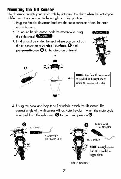
Mounting the Tilt SensorThe tilt sensor protects your motorcycle by activating the alarm when the motorcycle is lifted from the side stand to the upright or riding position.
1. Plug the female tilt sensor lead into the male connector from the main alarm harness.
2. To mount the tilt sensor, park the motorcycle using the side stand.
3. Find a location under the seat where you can attach the tilt sensor on a vertical surface and perpendicular to the direction of travel.
4. Using the hook and loop tape (included), attach the tilt sensor. The correct angle of the tilt sensor will activate the alarm when the motorcycle
is moved from the side stand to the riding position .
Diagram 1Diagram 1
A
B
TILT SENSOR
TILT SENSORBLACK WIRE TO ALARM UNIT
BLACK WIRE TO ALARM UNIT
C D
�NOTE: An angle greater than 30˚ is needed to trigger alarm.
RIDING POSITION
C D
7
NOTE: Wire from tilt sensor must be installed on the right side as shown. (As shown from back of bike)
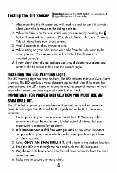
Testing the Tilt Sensor
1. After mounting the tilt sensor you will need to check to see if it activates when your bike is moved to the riding position.
2. While the bike is on the side-stand, arm your alarm by pressing the button 3 times within 3 seconds. (You should hear 1 chirp and 2 beeps). This will de-activate your shock sensor.
3. Wait 5 seconds to allow system to arm.4. While sitting on your bike, move your bike from the side stand to the riding position. Your alarm siren will activate if the tilt sensor is mounted correctly.5. If your alarm siren did not activate you should disarm your alarm and
reattach the tilt sensor to fine tune the correct angle.
Installing the LED Warning LightThe LED Warning Light has three functions. The LED indicates that your Cycle Alarm is armed. The LED provides a visual deterrent against theft. And if the alarm has been activated, the LED - based on a programmed sequence of flashes - lets you know which sensor has been triggered (current, tilt or shock).
IMPORTANT! FOR PROPER INSTALLATION YOU MUST USE AN 8MM DRILL BIT.The LED is held in place by an interference fit secured by the ridges below the bezel. A hole larger than 8mm will NOT properly secure the LED. This is very important!
1. Find a place on your motorcycle to mount the LED Warning Light - some where it can be easily seen, to alert potential thieves that your
motorcycle is protected by an alarm.2. It is important not to drill into your gas tank or any other important components on your motorcycle that will cause operational problems or safety hazards.3. Using ONLY AN 8MM DRILL BIT, drill a hole in the desired location.4. Feed the LED wire through the hole and push the LED into place.5. Plug the red LED female lead into the red male connector from the main
alarm harness.6. Make sure to secure any loose wires.
8
Important: Each sensor (TILT, SHOCK, CURRENT) has a 5 second delay. It is suggested that you count to 10 before testing.
9
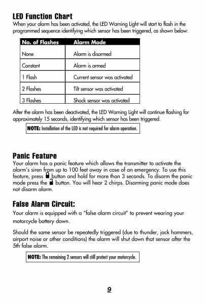
LED Function ChartWhen your alarm has been activated, the LED Warning Light will start to flash in the programmed sequence identifying which sensor has been triggered, as shown below:
No. of Flashes Alarm Mode
None Alarm is disarmed
Constant Alarm is armed
1 Flash Current sensor was activated
2 Flashes Tilt sensor was activated
3 Flashes Shock sensor was activated
After the alarm has been deactivated, the LED Warning Light will continue flashing for approximately 15 seconds, identifying which sensor has been triggered.
�NOTE: Installation of the LED is not required for alarm operation.
Panic FeatureYour alarm has a panic feature which allows the transmitter to activate the alarm’s siren from up to 100 feet away in case of an emergency. To use this feature, press button and hold for more than 3 seconds. To disarm the panic mode press the button. You will hear 2 chirps. Disarming panic mode does not disarm alarm.
False Alarm Circuit: Your alarm is equipped with a “false alarm circuit” to prevent wearing your motorcycle battery down.
Should the same sensor be repeatedly triggered (due to thunder, jack hammers, airport noise or other conditions) the alarm will shut down that sensor after the 5th false alarm.
�NOTE: The remaining 2 sensors will still protect your motorcycle.
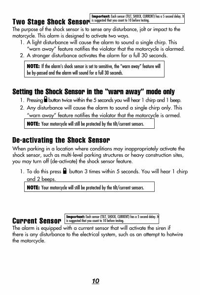
Two Stage Shock SensorThe purpose of the shock sensor is to sense any disturbance, jolt or impact to the motorcycle. This alarm is designed to activate two ways.
1. A light disturbance will cause the alarm to sound a single chirp. This “warn away” feature notifies the violator that the motorcycle is alarmed.
2. A stronger disturbance activates the alarm for a full 30 seconds.
� NOTE:�If the alarm’s shock sensor is set to sensitive, the “warn away” feature willbe by-passed and the alarm will sound for a full 30 seconds.
Setting the Shock Sensor in the “warn away” mode only1. Pressing button twice within the 5 seconds you will hear 1 chirp and 1 beep.2. Any disturbance will cause the alarm to sound a single chirp only. This
“warn away” feature notifies the violator that the motorcycle is armed.
NOTE:�Your motorcycle will still be protected by the tilt/current sensors.
De-activating the Shock SensorWhen parking in a location where conditions may inappropriately activate theshock sensor, such as multi-level parking structures or heavy construction sites, you may turn off (de-activate) the shock sensor feature.
1. To do this press button 3 times within 5 seconds. You will hear 1 chirp and 2 beeps.
NOTE:�Your motorcycle will still be protected by the tilt/current sensors.
Current SensorThe alarm is equipped with a current sensor that will activate the siren if there is any disturbance to the electrical system, such as an attempt to hotwire the motorcycle.
10
Important: Each sensor (TILT, SHOCK, CURRENT) has a 5 second delay. It is suggested that you count to 10 before testing.
Important: Each sensor (TILT, SHOCK, CURRENT) has a 5 second delay. It is suggested that you count to 10 before testing.
Setting the Alarm SensitivityYour alarm is manufactured with the sensitivity feature pre-set at the factory. If you wish to adjust the sensitivity, using the remote transmitter, you can select from 7 levels of sensitivity as well as de-activating the shock sensor. 1. Within 5 seconds of disarming alarm, press and hold button for
3 seconds (you will hear a click). 2. Press button to scroll through the seven (7) levels of sensitivity. The higher the pitch of tone, the more sensitive the alarm is to shock (the chirp sound de-activates the shock sensor). At each level you can test the shock sensitivity by tapping the handlebars or a different part of the motorcycle. 3. Press and hold the button when you have selected the proper level.
(You will hear 2 beeps).
�NOTE: To avoid false alarms, do not set the unit to be overly sensitive.
Selecting the Siren TonesYour alarm has been pre-set at the factory with the multi 5-tone alarm siren. If you should wish to change the siren tone from the multi 5-tone siren to one single tone, follow the directions below.1. Within 5 seconds of disarming your alarm press and hold button for 3 seconds. (You will hear a click). 2. Press button to scroll through the multi siren tones. 3. Press and hold the button when you have selected the siren tone
you wish to save. (You will hear 2 beeps).
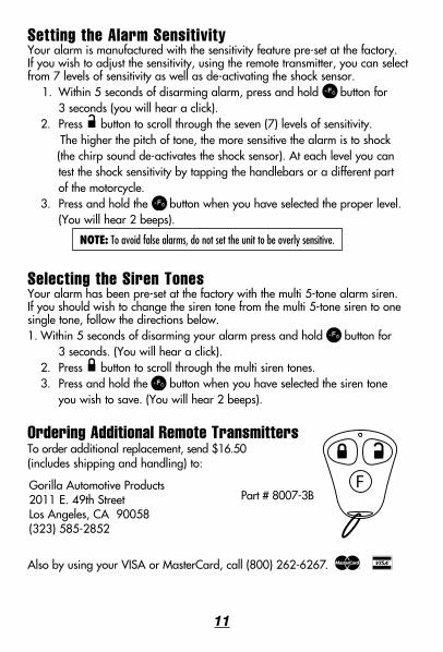
Ordering Additional Remote TransmittersTo order additional replacement, send $16.50 (includes shipping and handling) to:
Also by using your VISA or MasterCard, call (800) 262-6267. m v
11
Part # 8007-3BGorilla Automotive Products 2011 E. 49th Street Los Angeles, CA 90058(323) 585-2852
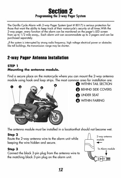
2-way Pager Antenna Installation
STEP 1Mounting the antenna module.
Find a secure place on the motorcycle where you can mount the 2-way antenna module using hook and loop strips. The most common area for installation are:
The antenna module must be installed in a locationthat should not become wet.
Step 2 Route the 2-way antenna wire to the alarm unit while keeping the wire hidden and secure.
Step 3 Connect the black 3-pin plug from the antenna wire to the matching black 3-pin plug on the alarm unit.
Section 2Programming the 2-way Pager System
12
The Gorilla Cycle Alarm with 2-way Pager System (part # 8017) is serious protection for those that want the ability to keep track of their motorcycle’s security at all times.With the 2-way pager, every function of the alarm can be monitored on the pager’s LED screen from up to 1/2 mile away*. Each alarm unit can accommodate up to 3 pagers and can be purchased separately.
*If the system is interrupted by strong radio frequency, high voltage electrical power or obstacles like tall buildings, the transmission range may be shorten.
1
2
3
4
1 2 34
To Alarm module
WITHIN TAIL SECTION
BEHIND SIDE COVERS
UNDER SEAT
WITHIN FAIRING
2-way antenna module
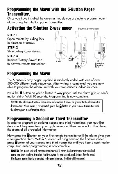
Programming the Alarm with the 5-Button Pager Transmitter.Once you have installed the antenna module you are able to program your alarm using the 5-button pager transmitter.
Activating the 5-button 2-way pager STEP 1 Open remote by sliding lock in direction of arrow. STEP 2 Slide battery cover down.STEP 3 Remove“Battery Saver” tab to activate remote transmitter.
Programming the AlarmThe 5-button 2-way pager supplied is randomly coded with one of over 500,000 different code sequences. After wiring is completed, you are now able to program the alarm unit with your transmitter’s individual code.
Press the button on your 5-button 2-way pager until the alarm gives a confir-mation chirp. Wait 10 seconds. Programming is now complete.
Programming a Second or Third TransmitterIn order to program an optional second and third transmitter, you must first disconnect the power from your cycle alarm and then reconnect it. This clears the alarm of all pre-coded information.
Now press the button on your first remote transmitter until the alarm gives you a confirmation chirp. Within 5 seconds of programming the first transmitter, press button of your second and third transmitter until you hear a confirmation chirp. Transmitter programming is now complete.
NOTE: The alarm unit will not retain code information if power or ground to the alarm unit is disconnected. When alarm is reconnected, press the button on your remote transmitter until the alarm gives a confirmation chirp.
NOTE: The alarm unit will accept a maximum of 3 codes. Each transmitter activated will cause the siren to chirp. Once for the first, twice for the second, and 3 times for the third. If a fourth transmitter is attempted to be programmed, the first will be erased.
13
5-button 2-way pager
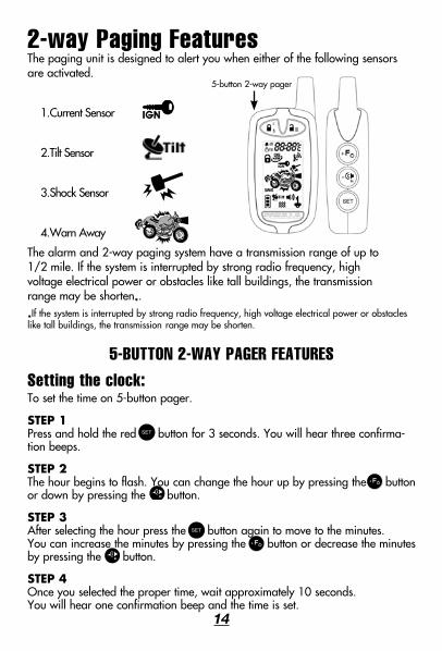
2-way Paging FeaturesThe paging unit is designed to alert you when either of the following sensors are activated.
1. Current Sensor
2. Tilt Sensor
3. Shock Sensor
4. Warn Away
The alarm and 2-way paging system have a transmission range of up to 1/2 mile. If the system is interrupted by strong radio frequency, high voltage electrical power or obstacles like tall buildings, the transmission range may be shorten*.
*If the system is interrupted by strong radio frequency, high voltage electrical power or obstacles like tall buildings, the transmission range may be shorten.
5-BUTTON 2-WAY PAGER FEATURESSetting the clock: To set the time on 5-button pager.
STEP 1 Press and hold the red button for 3 seconds. You will hear three confirma-tion beeps.
STEP 2 The hour begins to flash. You can change the hour up by pressing the button or down by pressing the button.
STEP 3 After selecting the hour press the button again to move to the minutes. You can increase the minutes by pressing the button or decrease the minutes by pressing the button.
STEP 4 Once you selected the proper time, wait approximately 10 seconds. You will hear one confirmation beep and the time is set.
14
5-button 2-way pager
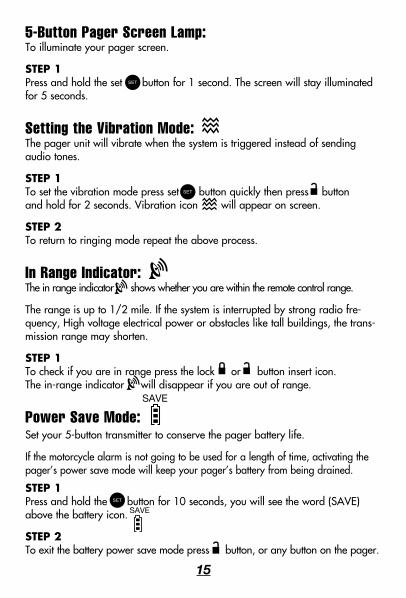
5-Button Pager Screen Lamp:To illuminate your pager screen.
STEP 1 Press and hold the set button for 1 second. The screen will stay illuminated for 5 seconds.
Setting the Vibration Mode:The pager unit will vibrate when the system is triggered instead of sending audio tones.
STEP 1 To set the vibration mode press set button quickly then press button and hold for 2 seconds. Vibration icon will appear on screen.
STEP 2 To return to ringing mode repeat the above process.
In Range Indicator: The in range indicator shows whether you are within the remote control range.
The range is up to 1/2 mile. If the system is interrupted by strong radio fre-quency, High voltage electrical power or obstacles like tall buildings, the trans-mission range may shorten.
STEP 1 To check if you are in range press the lock or button insert icon. The in-range indicator will disappear if you are out of range.
Power Save Mode: Set your 5-button transmitter to conserve the pager battery life.
If the motorcycle alarm is not going to be used for a length of time, activating the pager’s power save mode will keep your pager’s battery from being drained.
STEP 1 Press and hold the button for 10 seconds, you will see the word (SAVE) above the battery icon.
STEP 2 To exit the battery power save mode press button, or any button on the pager.
15
SAVE
SAVE
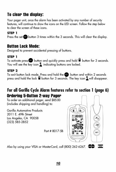
To clear the display: Your pager unit, once the alarm has been activated by any number of security features, will continue to show the icons on the LED screen. Follow the step below to clear the screen of these icons.
STEP 1 Press the set button 3 times within the 3 seconds. This will clear the display.
Button Lock Mode: Designed to prevent accidental pressing of buttons.
STEP 1 To activate press button and quickly press and hold button for 3 seconds. You will see the key icon indicating buttons are locked.
STEP 2 To exit button lock mode. Press and hold the button and within 2 seconds press and hold the lock button for 3 seconds. The key icon will disappear.
For all Gorilla Cycle Alarm features refer to section 1 (page 6)
16
m v
Ordering 5-Button 2-way PagerTo order an additional pager, send $85.00 (includes shipping and handling) to:
Also by using your VISA or MasterCard, call (800) 262-6267.
Gorilla Automotive Products 2011 E. 49th Street Los Angeles, CA 90058(323) 585-2852
Part # 8017-5B