Embed Size (px)
Citation preview

OWNER’S MANUAL
CP, CB Series Centrifugal Pump
© 2014 Pentair Ltd. All Rights Reserved. BE873 (02/28/14)
293 WRIGHT STREET, DELAVAN, WI 53115 WWW.BERkELEyPumPS.COmPH: 888-782-7483
MODELSMedium Head – Noryl® ImpellersMedium Head – Brass Impellers
High Head – Noryl® ImpellersHigh Head – Brass Impellers
1/3 through 2-1/2 H.P.:115/230 Volt Single Phase
230 Volt Single Phase230/460 Volt Three Phase

Ro
tatio
n
Support suction pipeas required, so thatpump does not takeweight of pipe
Support discharge pipeas required, so thatpump does not takeweight of pipe
As closeas possible
4 x "D"minimum
submergence
Foot Valve
Pipe diameter"D"
Straight run, as short aspossible but at least 6times pipe diameter ("D").Slope pipe down from pump to water
Short length of straight pipeafter reducer
Important:All connections mustbe air tight
Solid, levelbase
Tee andPriming Plug
Rotated Volute
StopValve
Union
Discharge to service
Recommended pump suctionand discharge connections
VentPlug
PrimingPlug
Street Elbow
Not recommended pump suctionand discharge connections
Elbow immediately in front of pump suction.
On the discharge avoid:Quick closing valves.Small I.D. pipe.Numerous fittings.Misalignment.Sharp turns in piping run.
Highlift
Pipe diameter "D"insufficient size
Pipe submergedless than 4 x "D"will cause vortexing
Long suctionrun
ConcentricReducer
Use of excess fittingsmeans potential air leaks
Valve
UnsupportedPipe
Concentric Reducer causes highspots along the suction line resultingin air pockets.
1226 0894
Eccentric Reducer,Straight side up
Figure 1
Figure 2
2

3
PIPING - GENERALSupport both suction and discharge piping independently at a point near the pump to avoid putting a strain on the pump housing. Start all piping AT THE PUMP.Increase pipe diameter at both the suction and discharge by one (1) standard pipe size (minimum) to obtain desired performance and flow rate. Refer to Table I when sizing pipe for your pumping system.NOTICE: Do not use pipe with smaller diameter on the suc-tion side of pump.
TABLE I Pump Port Recommended Size (NPT) Pipe Size
Suction Discharge Suction Discharge 1-1/4 1 1-1/2 1-1/4 1-1/2 1-1/4 2 1-1/2 2 1-1/2 3 2
SUCTION PIPEIncrease pipe size from pump suction port as shown in Table I.Figure 1 (Page 2) depicts a recommended run of pipe and fittings for the suction side of a centrifugal pump. Please refer to this illustration when choosing pipe and fittings for your suction connection.IMPORTANT: All connections must be air tight!Figure 2 (Page 2) depicts conditions that are NOT DESIRABLE on the suction side of a centrifugal pump and may cause problems in flow rate and priming. Please look this illustration over carefully before choosing pipe and fittings for your suction connection.
DISCHARGE PIPINGIncrease pipe size from pump discharge port as shown in Table I. Figure 1 (Page 2) depicts a recommended run of pipe and fittings for the discharge. Install tee with priming plug as close to pump as possible. Figure 2 (Page 2) notes conditions that should be avoided. Please read over carefully before making discharge connection.
PRIMING THE PUMPA pump is primed when all air in the suction line and pump volute has been evacuated and replaced with water.To Prime:1. Close valve in discharge line.2. Remove priming plug from tee and fill pump and suction
line with water until water is flowing back out of tee.3. Replace priming plug.4. Start pump and slowly open valve until desired water flow
is achieved. NOTICE: If water is not being pumped, turn off pump,
close valve, and repeat steps 1 thru 4.If pump volute is rotated as shown in Figure 1 (Page 2), loos-en vent plug when priming to evacuate air trapped inside volute. Tighten when volute is completely filled with water.NOTICE: Do not run the pump dry. This will damage mechan-ical seal and void warranty.
Burn hazard. Motor normally operates at high temperature and will be too hot to touch. It is protected from heat damage during operation by an automatic internal cut-off switch. Before handling pump or motor, stop motor and allow it to cool for 20 minutes.
TABLE II - RECOMMENDED FUSING AND WIRING DATA - 60 CYCLE MOTORS DIAMETER IN FEET FROM MOTOR TO METER BRANCH 0’ 51’ 101’ 201’ 301’ 401’ MOTOR MAX. LOAD FUSE* TO TO TO TO TO TO HP AMPERES RATING 50’ 100’ 200’ 300’ 400’ 500’ AMPS WIRE SIZE SINGLE PHASE - 115 VOLT 1/3 9.4 15 14 14 12 10 8 8 1/2 9.4 15 14 14 12 10 8 8 3/4 12.2 20 12 12 10 8 6 4 1 14.8 20 12 12 8 6 6 4 1-1/2 19.2 30 10 10 8 6 4 2 2 24.0 30 12 10 6 6 4 4 SINGLE PHASE - 230 VOLT 1/3 4.7 15 14 14 14 12 12 10 1/2 4.7 15 14 14 14 12 12 10 3/4 6.1 15 14 14 14 14 12 10 1 7.4 15 14 14 14 12 12 10 1-1/2 9.6 15 14 14 14 12 10 10 2 12.0 15 14 14 12 12 10 8 2-1/2 12.0 15 14 14 12 12 10 8 THREE PHASE - 230 VOLT 1/2 2.3 15 14 14 14 14 14 14 3/4 3.1 15 14 14 14 14 14 14 1 3.6 15 14 14 14 14 14 14 1-1/2 4.7 15 14 14 14 14 14 14 2 6.8 15 14 14 14 14 14 12 2-1/2 8.5 15 14 14 14 14 14 12 THREE PHASE - 460 VOLT 1/2 1.15 15 14 14 14 14 14 14 3/4 1.55 15 14 14 14 14 14 14 1 1.8 15 14 14 14 14 14 14 1-1/2 2.35 15 14 14 14 14 14 14 2 3.4 15 14 14 14 14 14 14 2-1/2 4.25 15 14 14 14 14 14 14
*A Fusetron is recommended instead of a fuse in any motor circuit.

4
Connection diagram for dual voltage, single-phase motors. Your dual-voltage motor’s terminal board (under the motor end cover) will match one of the diagrams below. Follow that diagram if necessary to convert motor to 115 Volt power. Connect power supply wires to L1 and L2. For 3-phase motors, or if motor does not match these pictures, follow the connection diagram on the motor nameplate.
THE MOTOR IS SET FOR 230 VOLTS WHEN SHIPPED.To change the motor to use 115 volts:1. Turn off power2. Remove the back motor cover.3. Use a screwdriver or 1/2” wrench and turn the voltage selector dial counterclockwise until 115 shows in the dial opening.4. Reinstall the motor cover.
Hazardous voltage. Can shock, burn, or cause death. Disconnect power to motor before working on pump or motor. Ground motor before connecting to power
supply.
WIRINGGround motor before connecting to electrical power supply. Failure to ground motor can cause severe or
fatal electrical shock hazard.
Do not ground to a gas supply line.To avoid dangerous or fatal electrical shock, turn OFF power to motor before working on electrical
connections.Supply voltage must be within ±10% of nameplate voltage. Incorrect voltage can cause fire or damage
motor and voids warranty. If in doubt consult a licensed electrician.
Use wire size specified in Wiring Chart (Page 3). If possible, connect pump to a separate branch circuit
with no other appliances on it.Wire motor according to diagram on motor name-plate. If nameplate diagram differs from diagrams
above, follow nameplate diagram.1. Install, ground, wire and maintain your pump in compli-
ance with the National Electrical Code (NEC) in the U.S., or the Canadian Electrical Code (CEC), as applicable, and with all local codes and ordinances that apply. Consult your local building inspector for code information.
2. Provide a correctly fused disconnect switch for protection while working on motor. For switch requirements, consult your local building inspector for information about codes.
3. Disconnect power before servicing motor or pump. If the disconnect switch is out of sight of pump, lock it open and tag it to prevent unexpected power application.
4. Ground the pump permanently using a wire of the same size as that specified in wiring chart (Page 3). Make ground connection to green grounding terminal under motor canopy marked GRD. or .
5. Connect ground wire to a grounded lead in the service panel or to a metal underground water pipe or well cas-ing at least 10 feet long. Do not connect to plastic pipe or insulated fittings.
6. Protect current carrying and grounding conductors from cuts, grease, heat, oil, and chemicals.
7. Connect current carrying conductors to terminals L1 and L2 under motor canopy. When replacing motor, check wiring diagram on motor nameplate against Figure 3. If the motor wiring diagram does not match either diagram in Figure 3, follow the diagram on the motor.
IMPORTANT: 115/230 Volt single phase models are shipped from factory with motor wired for 230 volts. If power supply is 115 volts, remove motor canopy and reconnect motor as shown in Figure 4. Do not try to run motor as received on 115 volt current.8. Motor has automatic internal thermal overload protection.
If motor has stopped for unknown reasons, thermal over-load may restart it unexpectedly, which could cause injury or property damage. Disconnect power before servicing motor.
9. If this procedure or the wiring diagrams are confusing, consult a licensed electrician.
ELECTRICAL
Figure 3: Changing the Voltage Setting
Figure 4: Motor Set for 115 Volt Operation

5
Seal Plate
Mechanical sealrotating half
Mechanical sealstationary half
A-Seal removal-rotating half B-Seal removal-stationary half C-Stationary half installation D-Rotating half installation
Turn over
Polishedsurface
Rubbersurface
Cardboardwasher
(supplied w/seal)
3/4" socket or pipe
Sealingface
Rubber drivering
Impeller
Shaftshoulder
5939 0109
FIGURE 5
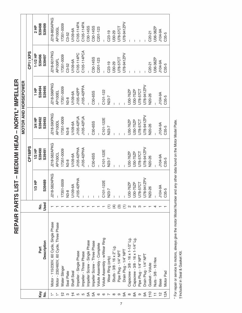
PUMP SERVICEThis centrifugal pump requires little or no service other than reasonable care and periodic cleaning. Occasionally, how-ever, a shaft seal (Key No. 4, Page 6) may become damaged and must be replaced. The procedure as outlined below will enable you to replace the seal.NOTICE: These mechanical seals are supplied with either a rubber seat ring or a sealing O-Ring. They are completely interchangeable.NOTICE: The highly polished and lapped faces of this seal are easily damaged. Read instructions and handle the seal with care.Some models are equipped with an impeller screw, which has a left hand thread. Before unscrewing the impeller, remove the impeller screw.
REMOVAL OF OLD SEAL1. After unscrewing impeller (Key No. 5, Page 6), care-
fully remove rotating part of seal by prying up on sealing washer, using two screwdrivers (see Figure 5A). Use care not to scratch motor shaft.
2. Remove seal plate (Key No. 3) from motor and place on flat surface, face down. Use a screwdriver to push ceramic seat out from seal cavity (see Figure 5B).
California Proposition 65 Warning This product and related accessories contain
chemicals known to the State of California to cause cancer, birth defects or other reproductive harm.
INSTALLATION OF FLOATING SEAT (Figure 5C)
1. Clean polished surface of floating (ceramic) seat with clean cloth.
2. Turn seal plate over so seal cavity is up; clean cavity thor-oughly.
3. Lubricate outside rubber surface or O-Ring of ceramic seat with soapy water and press firmly into seal cavity with finger pressure. If seat will not locate properly in this manner, place cardboard washer over polished face of seat and press into seal cavity using a 3/4” socket or 3/4” piece of standard pipe.
4. DISPOSE OF CARDBOARD WASHER. Be sure polished surface of seat is free of dirt and has not been damaged by insertion. Remove excess soapy water.
INSTALLATION OF ROTATING PART OF SEAL UNIT (Figure 5D)
1. Reinstall seal plate using extreme caution not to hit ceram-ic portion of seal on motor shaft.
2. Inspect shaft to make sure that it is clean.3. Clean face of sealing washer with clean cloth.4. Lubricate inside diameter and outer face of rubber drive
ring (see Figure 5D) with soapy water and slide assembly on motor shaft (sealing face first) until rubber drive ring hits shaft shoulder.
5. Screw impeller on shaft until impeller hub hits shaft shoulder. This will automatically locate seal in place and move the sealing washer face up against the facing seat. Reinstall impeller screw (if used).
SERVICE

6
111
2
3
104
7
5A
5
6
8
9
9A
12
12A
11
1227
089
4
Stu
d C
on
fig
ura
tio
n
Cap
scre
w C
on
fig
ura
tio
n
18A
2
3
104
7
5A
5
6
9
9A
12
12A
8A
1228
089
4
7
RE
PA
IR P
AR
TS
LIS
T –
ME
DIU
M H
EA
D –
NO
RY
L® IM
PE
LL
ER
M
OT
OR
AN
D H
OR
SE
PO
WE
R
C
P1M
PS
C
P11 / 4X
PS
1/3
HP
1/
2 H
P
3/4
HP
1
HP
1-
1/2
HP
2
HP
Key
P
art
No
.
S39
490
S39
492
S39
494
S39
496
S39
498
No
. D
escr
iptio
n
Use
d
S39
489
S39
491
S39
493
S39
495
S39
497
S39
499
1*
M
otor
- 11
5/23
0V, 6
0 Cy
cle, S
ingl
e Ph
ase
1 J2
18-5
82AP
KG
J218
-582
APKG
J2
18-5
90PK
G
J218
-596
PKG
J2
18-6
01PK
G
J218
-883
APKG
1*
M
otor
- 23
0/46
0V, 6
0 Cy
cle, T
hree
Pha
se
1 –
AP10
0CL
AP10
0DL
AP10
0EL
AP10
0FL
AP10
0GL
†2
Wat
er S
linge
r 1
1735
1-00
09
1735
1-00
09
1735
1-00
09
1735
1-00
09
1735
1-00
09
1735
1-00
09
3 Se
al P
late
1
N3-8
N3
-8
N3-8
N3
-8
C3-5
2 C3
-52
†4
Shaf
t Sea
l 1
U109
-6A
U109
-6A
U109
-6A
U109
-6A
U109
-6A
U109
-6A
5
Impe
ller -
Sin
gle
Phas
e 1
J105
-42P
HA
J105
-42P
HA
J105
-42P
JA
J105
-42P
P C1
05-1
14PC
C1
05-1
14PA
5
Impe
ller -
Thr
ee P
hase
1
– J1
05-4
2PHA
J1
05-4
2PJA
J1
05-4
2PPA
C1
05-1
14PC
A C1
05-1
14PA
5A
Impe
ller S
crew
- Si
ngle
Pha
se
1 –
– –
– –
C30-
14SS
5A
Impe
ller S
crew
- Th
ree
Phas
e
1 –
C30-
6SS
C30-
6SS
C30-
6SS
C30-
14SS
C3
0-14
SS
6 Vo
lute
Ass
embl
y - C
ompl
ete
1 –
– –
– C2
01-1
23
C201
-123
6
Volu
te A
ssem
bly
- w/W
ear R
ing
1 C1
01-1
22E
C101
-122
E C1
01-1
22E
C101
-122
–
–
7
Wea
r Rin
g (o
nly)
(1
) N2
3-7
N23-
7 N2
3-7
N23-
7 C2
3-19
C2
3-19
8
St
uds
- 3/8
- 16
x 2
” Lg.
(4
) –
– –
– U3
0-29
U3
0-29
9
Pi
pe P
lug
- 1/4
” NPT
(3
) –
– –
– U7
8-57
CT
U78-
57CT
9A
Dr
ain
Plug
- 1/
4” N
PT
(1)
– –
– –
U78-
941Z
PV
U78-
941Z
PV
8 Ca
pscr
ew -
3/8
- 16
x 1-
1/2”
Lg.
2
U30-
76ZP
U3
0-76
ZP
U30-
76ZP
U3
0-76
ZP
– –
8A
Caps
crew
- 3/
8 - 1
6 x
1-1/
4” L
g.
2 U3
0-75
ZP
U30-
75ZP
U3
0-75
ZP
U30-
75ZP
–
–
9 Pi
pe P
lug
- 1/4
” NPT
3
U78-
57CT
U7
8-57
CT
U78-
57CT
U7
8-57
CT
– –
9A
Drai
n Pl
ug -
1/4”
NPT
1
U78-
941Z
PV
U78-
941Z
PV
U78-
941Z
PV
U78-
941Z
PV
– –
†10
G
aske
t - V
olut
e 1
N20-
26
N20-
26
N20-
26
N20-
26
C20-
21
C20-
21 1
1 Nu
ts -
3/8
- 16
Hex
4 –
– –
– U3
6-38
ZP
U36-
38ZP
12
Base
1
J104
-9A
J104
-9A
J104
-9A
J104
-9A
J104
-9A
J104
-9A
12A
M
otor
Pad
1
C35-
5 C3
5-5
C35-
5 C3
5-5
C35-
5 C3
5-5
* For
repa
ir or
ser
vice
to m
otor
s, alw
ays
give
the
mot
or M
odel
Num
ber a
nd a
ny o
ther
dat
a fo
und
on th
e M
otor
Mod
el Pl
ate.
† Inc
lude
d in
Sea
l & G
aske
t Kit.

8
RE
PA
IR P
AR
TS
LIS
T –
ME
DIU
M H
EA
D –
BR
AS
S IM
PE
LL
ER
M
OT
OR
AN
D H
OR
SE
PO
WE
R
C
B1M
PS
C
B11 / 4X
PS
C
B11 / 2X
PS
1/2
HP
3/
4 H
P
1 H
P
1-1/
2 H
P
2 H
P
2-1/
2 H
P K
ey
Par
t N
o.
S39
503
S39
505
S39
507
S39
509
S39
511
S39
513
No
. D
escr
ipti
on
U
sed
S
3950
4 S
3950
6 S
3950
8 S
3951
0 S
3951
2 S
3951
4
1*
M
otor
- 11
5/23
0V, 6
0 C
ycle
, Sin
gle
Phas
e 1
J218
-582
APKG
J2
18-5
90PK
G
J218
-596
PKG
J2
18-6
01PK
G
J218
-883
APKG
–
1*
M
otor
- 23
0/46
0V, 6
0 C
ycle
, Thr
ee P
hase
1
AP10
0CL
AP10
0DL
AP10
0EL
AP10
0FL
AP10
0GL
AP10
0G5L
†2
Wat
er S
linge
r 1
1735
1-00
09
1735
1-00
09
1735
1-00
09
1735
1-00
09
1735
1-00
09
1735
1-00
09
3 Se
al P
late
1
N3-
8 N
3-8
N3-
8 C
3-52
C
3-52
C
3-52
†4
Shaf
t Sea
l 1
U10
9-6A
U
109-
6A
U10
9-6A
U
109-
6A
U10
9-6A
U
109-
6A
5 Im
pelle
r - S
ingl
e Ph
ase
1 J1
05-4
2MA
J105
-42L
A J1
05-4
2NA
C10
5-79
B C
105-
73BA
C
105-
80BA
5
Impe
ller -
Thr
ee P
hase
1
J105
-42M
A J1
05-4
2LA
J105
-42N
A C
105-
79BA
C
105-
73BA
C
105-
80BA
5A
Impe
ller S
crew
- Si
ngle
Pha
se
1 –
– –
– C
30-1
4SS
C30
-14S
S 5
A Im
pelle
r Scr
ew -
Thre
e Ph
ase
1
C30
-6SS
C
30-6
SS
C30
-6SS
C
30-1
4SS
C30
-14S
S C
30-1
4SS
6
Volu
te A
ssem
bly
- Com
plet
e 1
– –
– C
201-
123
C20
1-12
3 C
201-
123B
6
Volu
te A
ssem
bly
- w/W
ear R
ing
1 C
101-
122E
C
101-
122E
C
101-
122
– –
–
7
Wea
r Rin
g (o
nly)
(1
) N
23-2
7 N
23-2
7 N
23-2
7 C
23-1
9 C
23-1
9 C
23-1
9
8
Stud
s - 3
/8 -
16 x
2” L
g.
(4)
– –
– U
30-2
9 U
30-2
9 U
30-2
9
9
Pipe
Plu
g - 1
/4” N
PT
(3)
– –
– U
78-5
7CT
U78
-57C
T U
78-5
7CT
9A
D
rain
Plu
g - 1
/4” N
PT
(1)
– –
– U
78-9
41ZP
V U
78-9
41ZP
V U
78-9
41ZP
V
8 C
apsc
rew
- 3/
8 - 1
6 x
1-1/
2” L
g.
2 U
30-7
6ZP
U30
-76Z
P U
30-7
6ZP
– –
– 8
A C
apsc
rew
- 3/
8 - 1
6 x
1-1/
4” L
g.
2 U
30-7
5ZP
U30
-75Z
P U
30-7
5ZP
– –
–
9 Pi
pe P
lug
- 1/4
” NPT
3
U78
-57C
T U
78-5
7CT
U78
-57C
T –
– –
9A
Dra
in P
lug
- 1/4
” NPT
1
U78
-941
ZPV
U78
-941
ZPV
U78
-941
ZPV
– –
– †
10
Gas
ket -
Vol
ute
1 N
20-2
6 N
20-2
6 N
20-2
6 C
20-2
1 C
20-2
1 C
20-2
1 1
1 N
uts
- 3/8
- 16
Hex
4
– –
– U
36-3
8ZP
U36
-38Z
P U
36-3
8C 1
2 Ba
se
1 J1
04-9
A J1
04-9
A J1
04-9
A J1
04-9
A J1
04-9
A J1
04-9
F 1
2A
Mot
or P
ad
1 C
35-5
C
35-5
C
35-5
C
35-5
C
35-5
C
35-5
* For
repa
ir or
ser
vice
to m
otor
s, a
lway
s gi
ve th
e m
otor
Mod
el N
umbe
r and
any
oth
er d
ata
foun
d on
the
Mot
or M
odel
Pla
te.
† Inc
lude
d in
Sea
l & G
aske
t Kit.

9
RE
PA
IR P
AR
TS
LIS
T –
HIG
H H
EA
D –
NO
RY
L® IM
PE
LL
ER
M
OT
OR
AN
D H
OR
SE
PO
WE
R
C
P1X
PH
S
CP
11 / 4TP
HS
C
P11 / 2T
PH
S
1/
2 H
P
3/4
HP
1
HP
1-
1/2
HP
2
HP
2-
1/2
HP
Key
P
art
No
. S
3951
6 S
3951
8 S
3952
0 S
3952
2 S
3952
4 S
3952
6 N
o.
Des
crip
tio
n
Use
d
S39
517
S39
519
S39
521
S39
523
S39
525
S39
527
1*
M
otor
- 11
5/23
0V, 6
0 C
ycle
, Sin
gle
Phas
e 1
J218
-582
APKG
J2
18-5
90PK
G
J218
-596
PKG
J2
18-6
01PK
G
J218
-883
APKG
J2
18-6
28AP
KG
1*
Mot
or -
230/
460V
, 60
Cyc
le, T
hree
Pha
se
1 AP
100C
L AP
100D
L AP
100E
L AP
100F
L AP
100G
L AP
100G
5L †
2 W
ater
Slin
ger
1 17
351-
0009
17
351-
0009
17
351-
0009
17
351-
0009
17
351-
0009
17
351-
0009
3
Seal
Pla
te
1 C
3-10
42P
C3-
1042
P C
3-10
42P
C3-
1042
P C
3-18
1 C
3-18
1 †
4 Sh
aft S
eal
1 U
109-
6A
U10
9-6A
U
109-
6A
U10
9-6A
U
109-
93SS
U
109-
93SS
5
Impe
ller -
Sin
gle
Phas
e 1
C10
5-92
PN
C10
5-92
PM
C10
5-92
PL
C10
5-92
PB
C10
5-21
4PC
A C
105-
214P
A
5 Im
pelle
r - T
hree
Pha
se
1 C
105-
92PN
A C
105-
92PM
A C
105-
92PL
A C
105-
92PB
A C
105-
214P
CA
C10
5-21
4PA
5A
Impe
ller S
crew
- Si
ngle
Pha
se
1 –
– –
– C
30-1
4SS
C30
-14S
S 5
A Im
pelle
r Scr
ew -
Thre
e Ph
ase
1
C30
-14S
S C
30-1
4SS
C30
-14S
S C
30-1
4SS
C30
-14S
S C
30-1
4SS
6
Volu
te A
ssem
bly
- Com
plet
e 1
C10
1-28
1E
C10
1-28
1E
C10
1-28
1E
C10
1-28
1E
C10
1-26
4E
C10
1-26
4E
7
Wea
r Rin
g (o
nly)
(1
) C
23-2
7 C
23-2
7 C
23-2
7 C
23-2
7 C
23-1
9 C
23-1
9
8
Cap
scre
w -
3/8
- 16
x 1”
2
– –
– –
U30
-74Z
P U
30-9
9SS
8A
C
apsc
rew
- 3/
8 - 1
6 x
1-1/
4”
2 U
30-7
5ZP
U30
-75Z
P U
30-7
5ZP
U30
-75Z
P U
30-7
5ZP
U30
-104
ZP
8
Cap
scre
w -
3/8
- 16
x 1-
1/2”
2
U30
-76Z
P U
30-7
6ZP
U30
-76Z
P U
30-7
6ZP
– –
9
Pi
pe P
lug
- 1/4
” NPT
(2
) U
78-5
7CT
U78
-57C
T U
78-5
7CT
U78
-57C
T U
78-5
7CT
U78
-57C
T 9
A
Dra
in P
lug
- 1/4
” NPT
(1
) U
78-9
41ZP
V U
78-9
41ZP
V U
78-9
41ZP
V U
78-9
41ZP
V U
78-9
41ZP
V U
78-9
41ZP
V †
10
Gas
ket -
Vol
ute
1 C
20-1
21
C20
-121
C
20-1
21
C20
-121
C
20-1
22
C20
-122
12
Base
1
J104
-9F
J104
-9F
J104
-9F
J104
-9F
J104
-9F
J104
-9F
12A
M
otor
Pad
1
C35
-5
C35
-5
C35
-5
C35
-5
C35
-5
C35
-5
* For
repa
ir or
ser
vice
to m
otor
s, a
lway
s gi
ve th
e m
otor
Mod
el N
umbe
r and
any
oth
er d
ata
foun
d on
the
Mot
or M
odel
Pla
te.
† Inc
lude
d in
Sea
l & G
aske
t Kit.

10
RE
PA
IR P
AR
TS
LIS
T –
HIG
H H
EA
D –
BR
AS
S IM
PE
LL
ER
M
OT
OR
AN
D H
OR
SE
PO
WE
R
C
B1X
PH
S
CB
11 / 4TP
HS
C
B11 / 2T
PH
S
1/
2 H
P
3/4
HP
1
HP
1-
1/2
HP
2
HP
2-
1/2
HP
Key
P
art
No
. S
3952
9 S
3953
1 S
3953
3 S
3953
5 S
3953
7 S
3953
9 N
o.
Des
crip
tio
n
Use
d
S39
530
S39
532
S39
534
S39
536
S39
538
S39
540
1*
M
otor
- 11
5/23
0V, 6
0 C
ycle
, Sin
gle
Phas
e 1
J218
-582
APKG
J2
18-5
90PK
G
J218
-596
PKG
J2
18-6
01PK
G
J218
-883
APKG
J2
18-6
28AP
KG
1*
Mot
or -
230/
460V
, 60
Cyc
le, T
hree
Pha
se
1 AP
100C
L AP
100D
L AP
100E
L AP
100F
L AP
100G
L AP
100G
5L †
2 W
ater
Slin
ger
1 17
351-
0009
17
351-
0009
17
351-
0009
17
351-
0009
17
351-
0009
17
351-
0009
3
Seal
Pla
te
1 C
3-10
42P
C3-
1042
P C
3-10
42P
C3-
1042
P C
3-18
1 C
3-18
1 †
4 Sh
aft S
eal
1 U
109-
6A
U10
9-6A
U
109-
6A
U10
9-6A
U
109-
6A
U10
9-6A
5
Impe
ller -
Sin
gle
Phas
e 1
C5-
256B
A C
5-25
6BAA
C
5-25
4B
C5-
254B
B C
5-25
7BB
C5-
257B
5
Impe
ller -
Thr
ee P
hase
1
C5-
256B
A C
5-25
6BAA
C
5-25
4BA
C5-
254B
C
C5-
257B
B C
5-25
7B 5
A Im
pelle
r Scr
ew -
Sing
le P
hase
1
– –
– –
C30
-14S
S C
30-1
4SS
5A
Impe
ller S
crew
- Th
ree
Phas
e
1 C
30-1
4SS
C30
-14S
S C
30-1
4SS
C30
-14S
S C
30-1
4SS
C30
-14S
S
6 Vo
lute
Ass
embl
y - C
ompl
ete
1 C
101-
281E
C
101-
281E
C
101-
281E
C
101-
281E
C
101-
264E
C
101-
264E
B
7
Wea
r Rin
g (o
nly)
(1
) C
23-2
7 C
23-2
7 C
23-2
7 C
23-2
7 C
23-1
9 C
23-1
9
8
Cap
scre
w -
3/8
- 16
x 1”
2
– –
– –
U30
-74Z
P U
30-7
4ZP
8A
C
apsc
rew
- 3/
8 - 1
6 x
1-1/
4”
2 U
30-7
5ZP
U30
-75Z
P U
30-7
5ZP
U30
-75Z
P U
30-7
5ZP
U30
-75Z
P
8
Cap
scre
w -
3/8
- 16
x 1-
1/2”
2
U30
-76Z
P U
30-7
6ZP
U30
-76Z
P U
30-7
6ZP
U30
-76Z
P U
30-7
6ZP
9
Pi
pe P
lug
- 1/4
” NPT
(3
) U
78-5
7CT
U78
-57C
T U
78-5
7CT
U78
-57C
T U
78-5
7CT
U78
-57C
T 9
A
Dra
in P
lug
- 1/4
” NPT
(1
) U
78-9
41ZP
V U
78-9
41ZP
V U
78-9
41ZP
V U
78-9
41ZP
V U
78-9
41ZP
V U
78-9
41ZP
V †
10
Gas
ket -
Vol
ute
1 C
20-1
21
C20
-121
C
20-1
21
C20
-121
C
20-1
22
C20
-122
12
Base
1
J104
-9A
J104
-9A
J104
-9A
J104
-9A
J104
-9A
J104
-9F
12A
M
otor
Pad
1
C35
-5
C35
-5
C35
-5
C35
-5
C35
-5
C35
-5
* For
repa
ir or
ser
vice
to m
otor
s, a
lway
s gi
ve th
e m
otor
Mod
el N
umbe
r and
any
oth
er d
ata
foun
d on
the
Mot
or M
odel
Pla
te.
† Inc
lude
d in
Sea
l & G
aske
t Kit.

11
TROUBLE - CAUSES AND REMEDY TROUBLE AND CAUSE REMEDY
FAILURE TO PUMP
1. Pump not properly primed. 1. Make sure pump casing and suction line are full of water. See priming instructions.
REDUCED CAPACITY AND/OR HEAD
1. Air pockets or leaks in suction line. 1. Check suction piping.
2. Clogged impeller. 2. Remove and clean.
PUMP LOSES PRIME
1. Air leaks in suction line. 1. Check suction piping
2. Excessive suction lift and operating 2. Move pump nearer to water level. too near shut-off point.
3. Water level drops while pumping, 3. Check water supply. Add length of pipe to suction uncovering suction piping. to keep submerged end under water.
MECHANICAL TROUBLES AND NOISE
1. Bent shaft and/or damaged bearings. 1. Take motor to authorized motor repair shop.
2. Suction and/or discharge piping not 2. See that all piping is supported to relieve strain properly supported and anchored. on pump assembly.