Embed Size (px)
Citation preview
Models of Battery Storage Systems for Power System Analysis
International Seminar on “Energy Storage Options for Renewable Energy Integration” “Energy Storage Options for Renewable Energy Integration”
at India Habitat Centre on 29th January 2018
Flavio FernandezDIgSILENT GmbH, Germany
Models of Battery Storage Systems for Power System Analysis
International Seminar on “Energy Storage Options for Renewable Energy Integration” “Energy Storage Options for Renewable Energy Integration”
at India Habitat Centre on 29th January 2018
Flavio FernandezGmbH, Germany

Outline
• Introduction
• Overview battery storage simulation models
• Application cases
- Transient stability analysis- Transient stability analysis
- Quasi-dynamic simulation
• Model validation
• Summary and Outlook
1st International Integration Conference, India
Overview battery storage simulation models
2
Introduction
• Battery storage is an effective tool to ensure system
grid levels, in particular with increasing penetration of variable renewable
generation (VRG) such as wind and photovoltaic
• It is anticipated an increasing deployment of battery storage systems at all grid
levels and therefore increasing needs for their simulation at system planning levels and therefore increasing needs for their simulation at system planning
and operation stage
• Simulation models
- The wider the range of applications, the
- Degree of detail of the simulation model has to be in line with the
discharge) and the response time of the battery storage system
application
1st International Integration Conference, India
Battery storage is an effective tool to ensure system flexibility and balancing at all
grid levels, in particular with increasing penetration of variable renewable
generation (VRG) such as wind and photovoltaic
It is anticipated an increasing deployment of battery storage systems at all grid
increasing needs for their simulation at system planning increasing needs for their simulation at system planning
the various the models required for simulation
Degree of detail of the simulation model has to be in line with the duration (of the
time of the battery storage system of the desired
3

Introduction
ApplicationGeneration Level
Description
Governor response
Automatic dynamic response of the generator to frequency changesStorage can compensate lack of governor response of VRG
1st International Integration Conference, India
Frequency regulation
Second by second adjustment of power to match load and regulate system frequencyStorage can free up generation capacity for energy production
Balancing/real-time dispatch
Adjustment of production market-based on minute by minute basis to match demandStorage can mitigates price spikes due to volability of VRG
Max. Power Requirement
Duration Requirement
Response
response of the Up to 10% of generator rating
Seconds to few minutes
Fast (miliseconds)
4
~ 5% of peak demand (large systems), can be higher in small islanded systems
~15-30 minutes
Fast (miliseconds)
based on minute by minute basis to
Storage can mitigates price spikes
1 hour or more Slow, max. up/down rampsacc. to grid code
Introduction
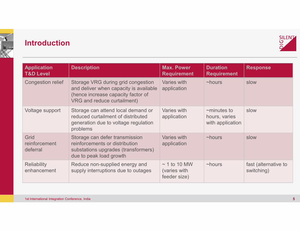
ApplicationT&D Level
Description
Congestion relief Storage VRG during grid congestion and deliver when capacity is available (hence increase capacity factor of VRG and reduce curtailment)
Voltage support Storage can attend local demand or reduced curtailment of distributed
1st International Integration Conference, India
reduced curtailment of distributed generation due to voltage regulation problems
Grid reinforcement deferral
Storage can defer transmission reinforcements or distribution substations upgrades (transformers) due to peak load growth
Reliability enhancement
Reduce non-supplied energy and supply interruptions due to outages
Max. Power Requirement
Duration Requirement
Response
grid congestion and deliver when capacity is available
Varies with application
~hours slow
Storage can attend local demand or Varies with application
~minutes to hours, varies
slow
5
to voltage regulation application hours, varies
with application
substations upgrades (transformers)
Varies with application
~hours slow
supply interruptions due to outages ~ 1 to 10 MW (varies with feeder size)
~hours fast (alternative to switching)
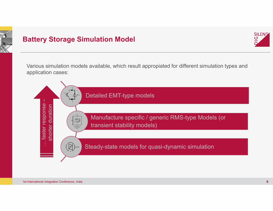
Battery Storage Simulation Model
Detailed EMT-type models
: faste
r re
sponse –
short
er
dura
tion
Various simulation models available, which result appropiated for different simulation types and application cases:
1st International Integration Conference, India
Manufacture specific / generic RMS
transient stability models)
Steady-state models for quasi: faste
r re
sponse
short
er
dura
tion
type models
Various simulation models available, which result appropiated for different simulation types and
6
Manufacture specific / generic RMS-type Models (or
transient stability models)
state models for quasi-dynamic simulation

Battery Storage Simulation Model
Current source (fund. Freq.)
1st International Integration Conference, India 7
Detailed EMT-models
Quasi-dynamic models
Battery Storage Simulation Model
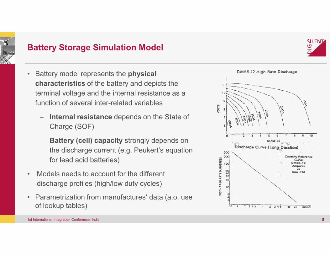
• Battery model represents the physical
characteristics of the battery and depicts the
terminal voltage and the internal resistance as a
function of several inter-related variables
− Internal resistance depends on the State of
Charge (SOF)
1st International Integration Conference, India
Charge (SOF)
− Battery (cell) capacity strongly depends on
the discharge current (e.g. Peukert‘s equation
for lead acid batteries)
• Models needs to account for the different
discharge profiles (high/low duty cycles)
• Parametrization from manufactures‘ data (a.o. use of lookup tables)
of the battery and depicts the
terminal voltage and the internal resistance as a
State of
8
strongly depends on
the discharge current (e.g. Peukert‘s equation
Models needs to account for the different
Parametrization from manufactures‘ data (a.o. use
Battery Storage Simulation Model
0
1
Frquency MeasurementElmPhi*
AC-VoltageStaVmea
Frame_BatteryCntrl:
PQ-MeasurementStaPqmea
Frequency ControlElmDsl*
1st International Integration Conference, India
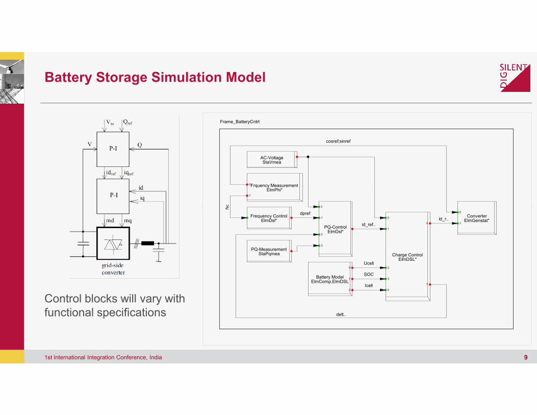
Control blocks will vary with functional specifications
0
Frquency MeasurementElmPhi*
AC-VoltageStaVmea
cosref;sinref
1
2
3
0
1
0
1
2
0
0
1
2
1
3
4
PQ-MeasurementStaPqmea
Frequency ControlElmDsl*
PQ-ControlElmDsl*
ConverterElmGenstat*
Battery ModelElmComp,ElmDSL
Charge ControlElmDSL*
id_ref..
id_r..
delt..
dpref
Icell
SOC
Ucell
9
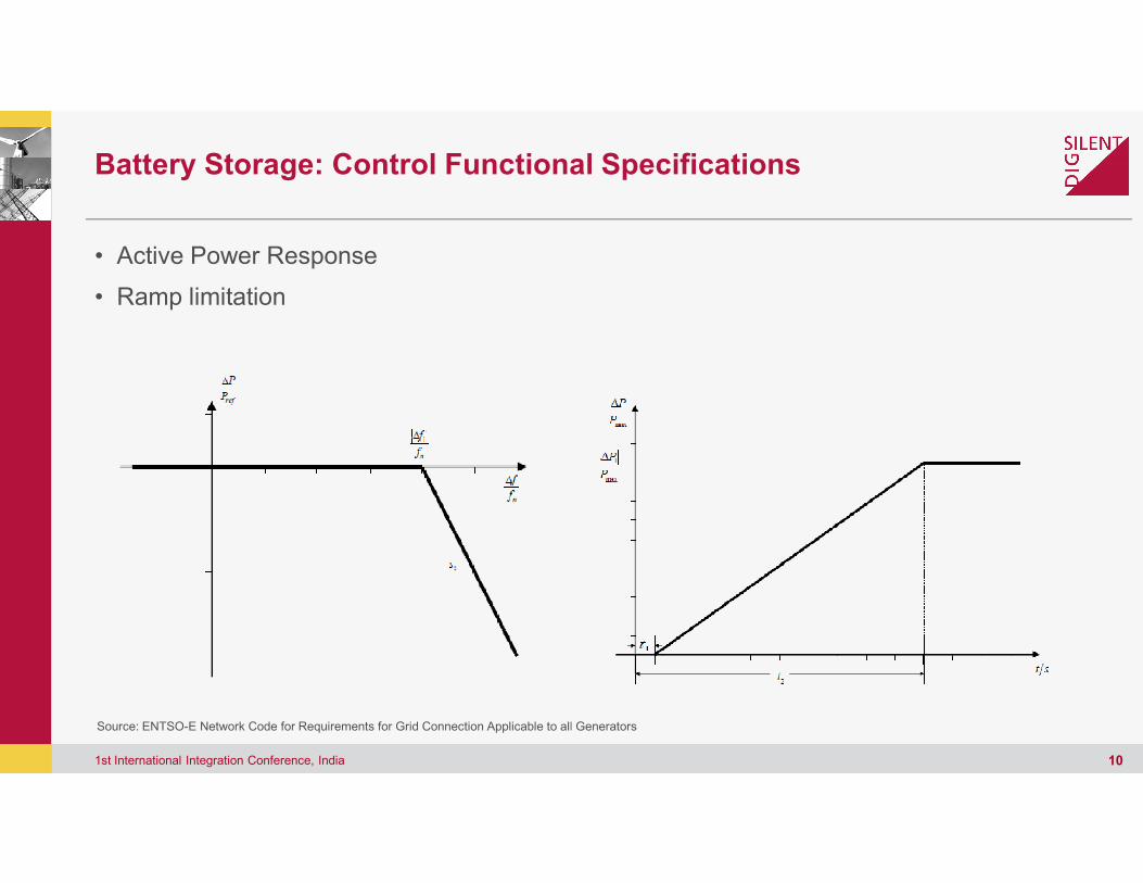
Battery Storage: Control Functional
• Active Power Response
• Ramp limitation
1st International Integration Conference, India
Source: ENTSO-E Network Code for Requirements for Grid Connection Applicable to all Generators
Functional Specifications
10
for Grid Connection Applicable to all Generators

Battery Storage: Control Functional Specifications
• Implementation in PowerFactory DSL Simulation language for frequency control
1
0
PV_Control:
pin
dpref
Frequency control
1st International Integration Conference, India
3
4
2
vref
vin
dpref
Functional Specifications
Implementation in PowerFactory DSL Simulation language for frequency control
0
PV_Control:
012
30123- {K+1/sT)}
Kp,Tip
id_max
(1/(1+sT))Tr
dp
deltai
yi2yi1id_ref
dpref
11
10123
-Deadband_Offset_Lim
AC_deadband,Kq
iq_max
iq_min
{1/sT}Tiq
iq_max
iq_min
0123
id_min
(1/(1+sT))Trq
dv
vref
vin iq_refo11deltaU(1)
dpref
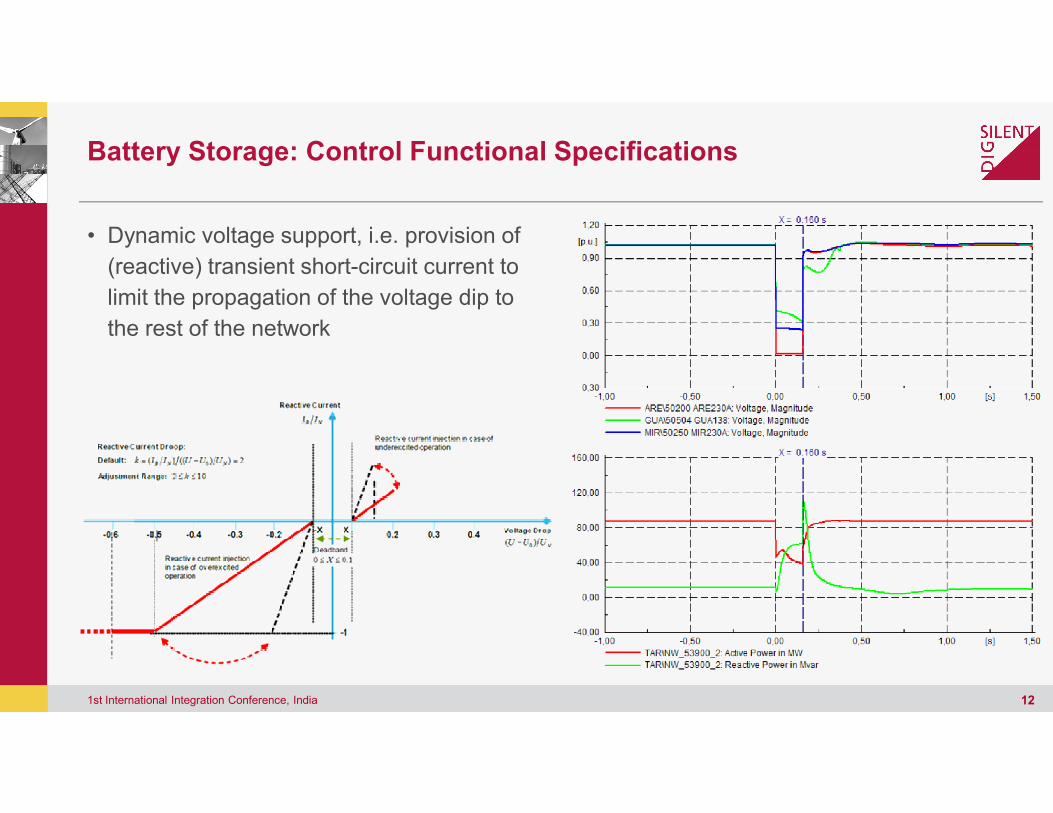
Battery Storage: Control Functional Specifications
• Dynamic voltage support, i.e. provision of
(reactive) transient short-circuit current to
limit the propagation of the voltage dip to
the rest of the network
1st International Integration Conference, India
Functional Specifications
12
Battery Storage: Control Functional Specifications
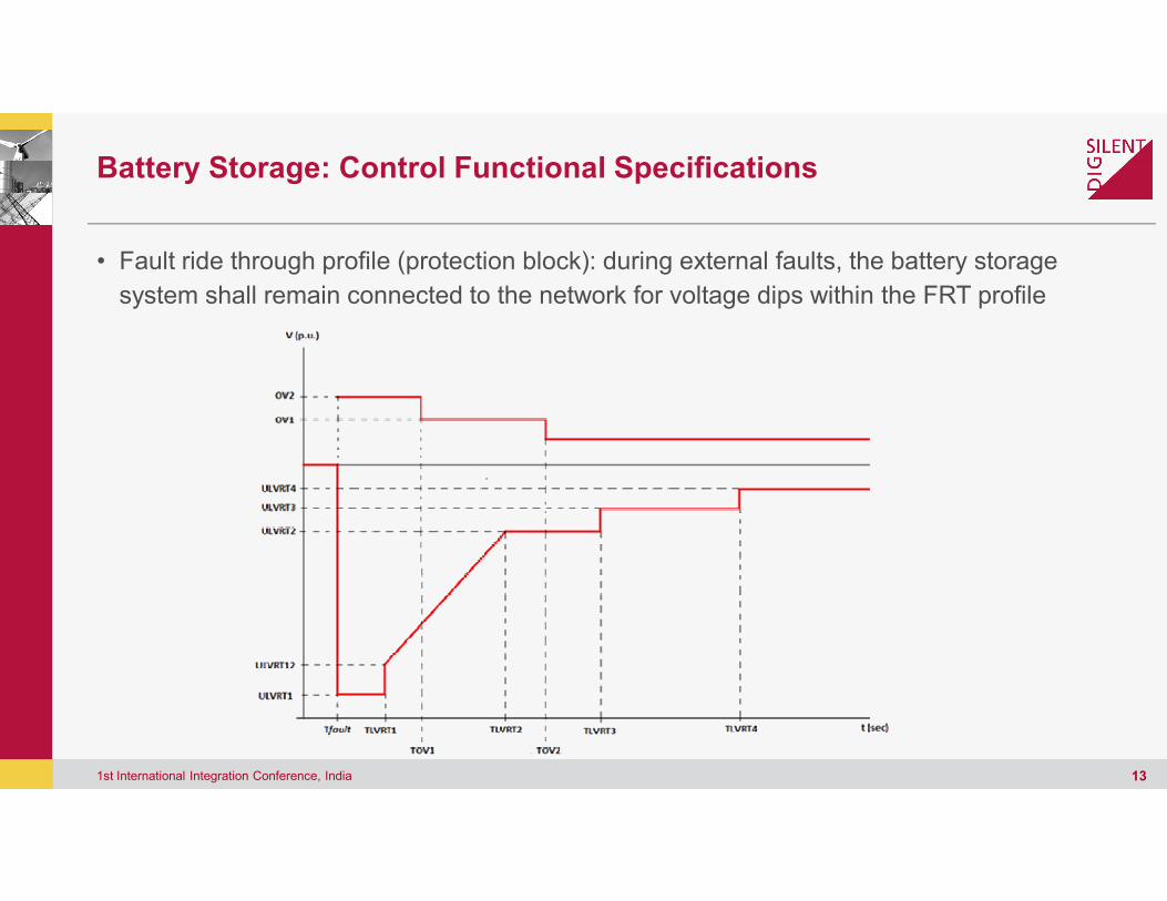
• Fault ride through profile (protection block): during external faults,
system shall remain connected to the network for voltage dips within the FRT profile
1st International Integration Conference, India
Functional Specifications
Fault ride through profile (protection block): during external faults, the battery storage
remain connected to the network for voltage dips within the FRT profile
13

Outline
• Introduccion
• Battery storage simulation models
• Application cases• Application cases
• Model validation
• Summary
1st International Integration Conference, India
Battery storage simulation models
14
Example 1: BESS for Frequency Regulation in Islanded System
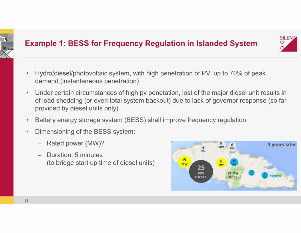
• Hydro/diesel/photovoltaic system, with high penetration of PV: up to 70% of peak demand (instantaneous penetration)
• Under certain circumstances of high pv penetation, lost of the major diesel unit results in of load shedding (or even total system backout) due to lack of governor response (so far provided by diesel units only)
• Battery energy storage system (BESS) shall improve frequency regulation
15
• Battery energy storage system (BESS) shall improve frequency regulation
• Dimensioning of the BESS system:
− Rated power (MW)?
− Duration: 5 minutes (to bridge start up time of diesel units)
Example 1: BESS for Frequency Regulation in Islanded System
Hydro/diesel/photovoltaic system, with high penetration of PV: up to 70% of peak
Under certain circumstances of high pv penetation, lost of the major diesel unit results in of load shedding (or even total system backout) due to lack of governor response (so far
Battery energy storage system (BESS) shall improve frequency regulation
4MW
9MW
6MW
6MW
Load
3MW
3 years later
Hydro
6MW
25MW
DIESEL3
MW
6MW
?? MW BESS
Battery energy storage system (BESS) shall improve frequency regulation
(to bridge start up time of diesel units)
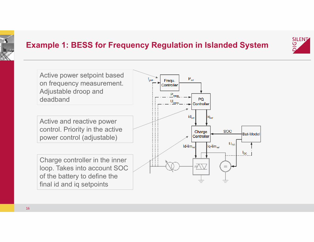
Active power setpoint basedon frequency measurement. Adjustable droop anddeadband
Active and reactive power
Example 1: BESS for Frequency Regulation in Islanded System
16
Active and reactive power control. Priority in the activepower control (adjustable)
Charge controller in the innerloop. Takes into account SOC of the battery to define thefinal id and iq setpoints
Example 1: BESS for Frequency Regulation in Islanded System
[Hz]
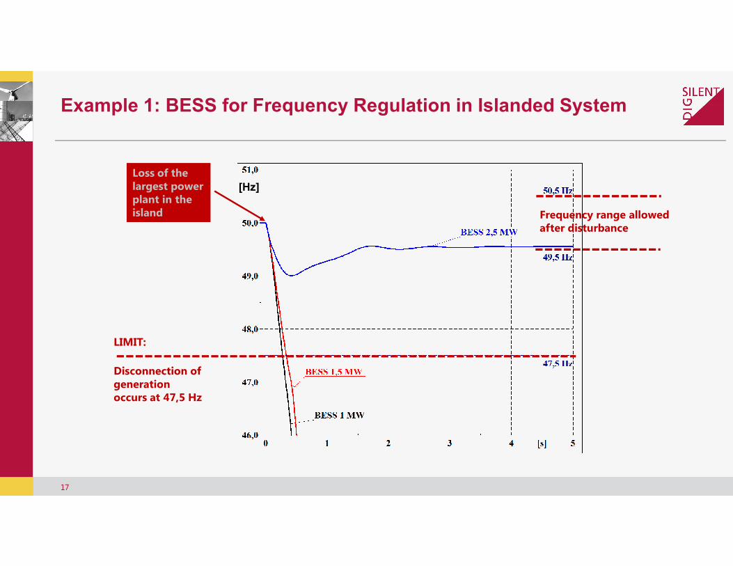
Loss of thelargest power plant in theisland
Example 1: BESS for Frequency Regulation in Islanded System
17
LIMIT:
Disconnection of generationoccurs at 47,5 Hz
Frequency range allowedafter disturbance
Example 1: BESS for Frequency Regulation in Islanded System

Example 2: Voltage control / MW Curtailment
• 2MW wind turbine generator connected at the remote end of a MV distribution feeder
• Frequent curtailment due to violaton of voltage constraints
− Voltage at PCC not allowed to exceed 1.04
− DNO curtails ative power injection to control voltage
18
− DNO curtails ative power injection to control voltage
• To enhance plant factor, a battery storage system shall storage curtailed generation and deliver it after voltage violation clearance
• Dimensioning of the BESS system:
− Rated power – fixed % of WTG rating, 0.4MW in this case
− Energy? – trade-off between BESS cost and total curtailed energy
Example 2: Voltage control / MW Curtailment
2MW wind turbine generator connected at the remote end of a
Frequent curtailment due to violaton of voltage constraints
exceed 1.04 p.u.
DNO curtails ative power injection to control voltageDNO curtails ative power injection to control voltage
To enhance plant factor, a battery storage system shall storage curtailed generation and deliver it after voltage violation
fixed % of WTG rating, 0.4MW in this case
off between BESS cost and total curtailed
Example 2: Voltage control / MW Curtailment
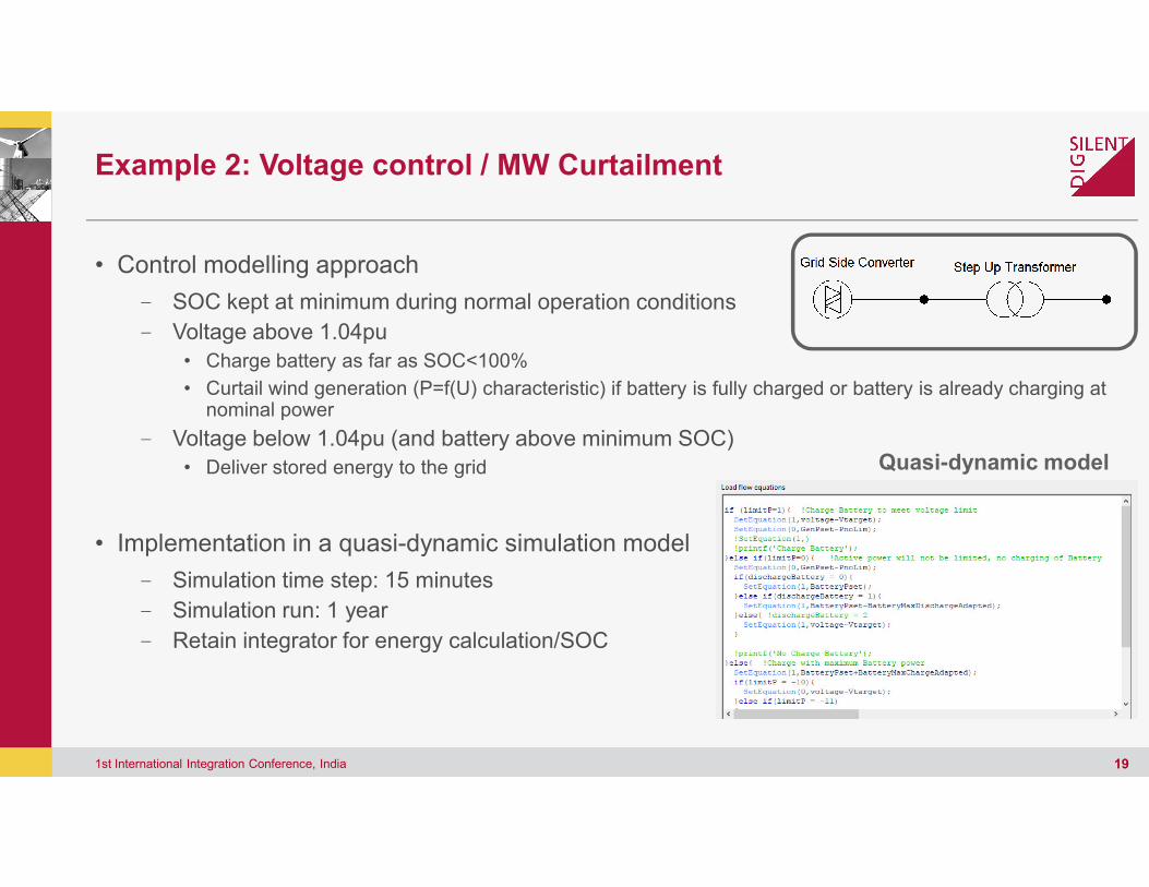
• Control modelling approach
- SOC kept at minimum during normal operation conditions
- Voltage above 1.04pu
• Charge battery as far as SOC<100%
• Curtail wind generation (P=f(U) characteristic) if battery is fully charged or battery is already charging at nominal power
- Voltage below 1.04pu (and battery above minimum SOC)- Voltage below 1.04pu (and battery above minimum SOC)
• Deliver stored energy to the grid
• Implementation in a quasi-dynamic simulation model
- Simulation time step: 15 minutes
- Simulation run: 1 year
- Retain integrator for energy calculation/SOC
1st International Integration Conference, India
Example 2: Voltage control / MW Curtailment
SOC kept at minimum during normal operation conditions
Curtail wind generation (P=f(U) characteristic) if battery is fully charged or battery is already charging at
Voltage below 1.04pu (and battery above minimum SOC)Voltage below 1.04pu (and battery above minimum SOC)
dynamic simulation model
Retain integrator for energy calculation/SOC
19
Quasi-dynamic model

Example 2: Voltage control / MW Curtailment
1st International Integration Conference, India
Example 2: Voltage control / MW Curtailment
20

Example 2: Voltage control / MW Curtailment
Assumptions:• Feed-In Tariff 0,10$/kWh• Storage costs 1.700$/kWh (life span 20 a)• Max charging power 0.4MW• Storage energy size from 0.4MWh – 2MWh
Battery size in MWh
CurtailedEnergy inMWh/year
Costs energycurtailed in Mill.$/20a
Batteryin Mill.$/20a(1.700$/kWh)
0 342 0,68 0
0,4 283 0,57 0,68
1 237 0,47 1,7
1,5 214 0,43 2,5
2 194 0,01 3,4
21
Example 2: Voltage control / MW Curtailment
Battery costsin Mill.$/20a
$/kWh)
0
0,68
1,7
2,5
3,4
0.68 0.57 0.47 0.430.010
0.68
1.7
2.5
3.4
0 0.4 1 1.5 2
Mil
lio
n $
MWh of installed battery capacity
Cost of curtailed energy Cost of Batteries
Outline
• Introduccion
• Battery storage simulation models
• Application cases
• Model validation
• Summary
1st International Integration Conference, India
Battery storage simulation models
22
Model Validation
• Certification of the Electrical Characteristics of Power Generating Units and
- In Germany, FGW developed guidelines for the certification of wind,
storage systems in the medium-, high and extra high
- Part 4: Demands on Modelling and Validating Simulation Models of the Electrical Characteristics
of Power Generating Units and Systems
• Required tests/measurements
• Comparison procedure: definition of stationary ranges, transient ranges, etc.
• Tolerance and error limits
• Database for manufacture specific models:
- http://www.wind-fgw.de/publikationen/datenbanken/
• Parametrization of generic models can be verified against manufacture specific models
1st International Integration Conference, India
of the Electrical Characteristics of Power Generating Units and Systems
In Germany, FGW developed guidelines for the certification of wind, pv, combusting engines,
, high and extra high-voltage grids
Part 4: Demands on Modelling and Validating Simulation Models of the Electrical Characteristics
Comparison procedure: definition of stationary ranges, transient ranges, etc.
Database for manufacture specific models:
fgw.de/publikationen/datenbanken/
Parametrization of generic models can be verified against manufacture specific models
23
Model Validation
1st International Integration Conference, India
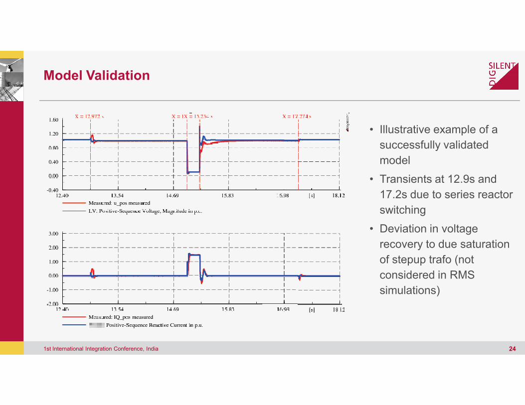
• Illustrative example of a
successfully validated
model
• Transients at 12.9s and
17.2s due to series reactor
switching
• Deviation in voltage
recovery to due saturation
of stepup trafo (not
considered in RMS
simulations)
24
Summary
• It is anticipated an increasing deployment of battery storage systems at all grid levels and
therefore increasing needs for simulation of battery storage systems
planning and operation stage
- Two examples shown particular application in combination with variable renewable generation
(VRG)
• Simulation model has to be fit for purpose• Simulation model has to be fit for purpose
- Details of the representation and simulation
discharge) and the response time of the battery storage system
(minutes to miliseconds)
- Model validation might be required for specific applications
1st International Integration Conference, India
It is anticipated an increasing deployment of battery storage systems at all grid levels and
increasing needs for simulation of battery storage systems at system
Two examples shown particular application in combination with variable renewable generation
fit for purposefit for purpose
Details of the representation and simulation step sizes have to in line with the duration (of the
time of the battery storage system of the desired application
might be required for specific applications
25
Summary
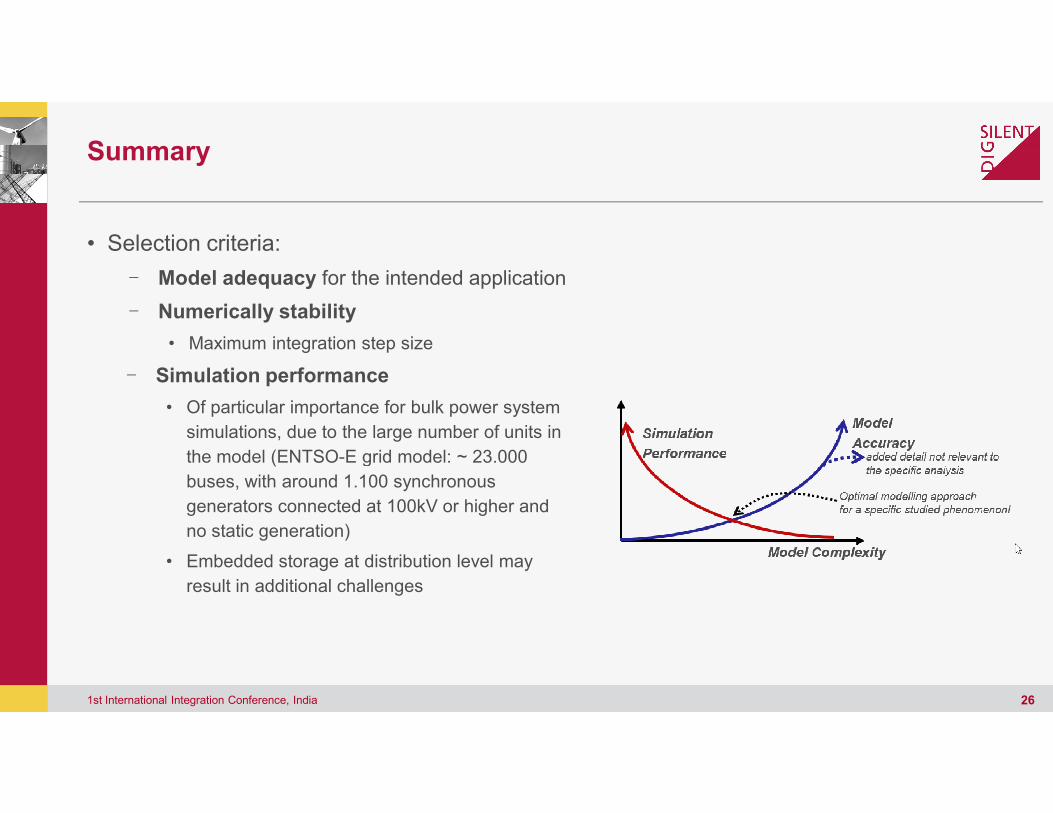
• Selection criteria:
- Model adequacy for the intended application
- Numerically stability
• Maximum integration step size
- Simulation performance
• Of particular importance for bulk power system
1st International Integration Conference, India
• Of particular importance for bulk power system
simulations, due to the large number of units in
the model (ENTSO-E grid model: ~ 23.000
buses, with around 1.100 synchronous
generators connected at 100kV or higher and
no static generation)
• Embedded storage at distribution level may
result in additional challenges
application
Of particular importance for bulk power system
26
Of particular importance for bulk power system
simulations, due to the large number of units in
E grid model: ~ 23.000
generators connected at 100kV or higher and
Embedded storage at distribution level may

Outlook
• Data exchange / Portability of dynamic models
- Promote the use of standard generic model
available
- Standard interface (e.g. IEC61400-27) for the exchange of compiled models
• Model aggregation
- Suitable aggregation of wind/pv generating units, retaining main park characteristics- Suitable aggregation of wind/pv generating units, retaining main park characteristics
1st International Integration Conference, India
Portability of dynamic models
Promote the use of standard generic model – parametrization by manufactures not always
27) for the exchange of compiled models
Suitable aggregation of wind/pv generating units, retaining main park characteristicsSuitable aggregation of wind/pv generating units, retaining main park characteristics
27

Thanks for your attention!
Flavio FernandezDIgSILENT GmbH, Germany
Thanks for your attention!
Flavio FernandezGmbH, Germany