Embed Size (px)
Citation preview

NOTE! To the installer: Please make sure you provide this manual to the owner of the equip ment or to the responsible party who maintains the system.
MODELS WGX30/50, WGX30H/50H/75H, VSX30/50 and VHX30/50/75Hazardous Locations Class I, Division 1, Groups C & DSUBMERSIBLE GRINDER PUMPSINSTALLATION AND SERVICE MANUALFor use with product built with RBC motor.
Part # 23833A656 | © 2018 Pentair plc | 4/16/18
(*Hazardous Location Motor End)
2
CAUTION!Read these safety warnings first before installing, servicing or operating any pump.
CALIFORNIA PROPOSITION 65 WARNING:
This product and related accessories contain chemicals known to the State of California to cause cancer, birth defects or other reproductive harm.
GENERAL1. Most accidents can be avoided by using
common sense.
2. Read the operation and maintenance instruction manual supplied with the pump.
3. Do not wear loose clothing that can become entangled in the impeller or other moving parts.
4. This pump is designed to handle materials which could cause illness or disease through direct exposure.
Wear adequate protective clothing when working on the pump or piping.
ELECTRICAL5. To reduce the risk of electrical shock, pump must be
properly grounded in accordance with the National Electric Code and all applicable state and local codes and ordinances.
6. To reduce risk of electrical shock, disconnect the pump from the power source before handling or servicing.
7. Any wiring to be done on pumps should be done by a qualified electrician.
8. Never operate a pump with a power cord that has frayed or brittle insulation.
9. Never let cords or plugs lay in water.
10. Never handle connected power cords with wet hands.
PUMPS11. Pump builds up heat and pressure during operation,
allow time for pump to cool before handling or servicing.
12. Only qualified personnel should install, operate or repair pump.
13. Keep clear of suction and discharge openings. Do not insert fingers into pump with power connected.
14. Do not pump hazardous material not recommended for pump (flammable, caustic, etc.).
15. Make sure lifting handles are securely fastened each time before lifting.
16. Do not lift pump by the power cord.
17. Do not exceed manufacturer's recommendation for maximum performance, as this could cause the motor to overheat.
18. Secure the pump in its operating position so it cannot tip over, fall or slide.
19. Keep hands and feet away from impeller when power is connected.
20. Submersible solids handling pumps are not approved for use in swimming pools, recreational water installations, decorative fountains or any installation where human contact with the pumped fluid is common.
21. Do not operate pump without safety devices in place.
IMPORTANT! Myers® is not responsible for losses, injury or death resulting from a failure to observe these safety precautions, misuse or abuse of pumps or equipment.
GENERAL INFORMATIONPump Models: These instructions cover the installation and service of the Myers pumps as listed on the front cover. The hazardous location models are Factory Mutual approved and listed hazardous location for hazardous sewage locations Class I, Division 1, Groups C & D.
Motor HP & Voltages: These pumps are offered in a three phase wiring configuration only. Voltages will vary according to the application.
Electrical Controls: All of these pump models must be used with a control panel. Myers-built control panels are designed to supply the correct electrical controls, motor starting equipment and include the circuitry for moisture and heat sensors. It is recommended that a Myers-built control panel be used so that all warranties apply.
General Construction: The motor construction is designed to meet Factory Mutual’s requirements for Class I, Division 1, Groups C & D sewage applications. The hazardous location models are certified and nameplated with this approval. The motor chamber and seal chamber are filled with a high dielectric type oil for improved lubrication and heat transfer of the bearings and motor. Since the bearings have been designed for 50,000 hours of life, the oil should never require replacement under normal operating conditions. An air space above the oil level in both the seal and motor chambers is provided to allow for the expansion of the oil when at operating temperature. The power and control lines are sealed and strain relieved by a grommet in the cord cap, and internally through the use of a dielectric potting resin surrounding the electrical wires. All of the pump fasteners and shafts are made from corrosion resistant stainless steel, while the pump castings are made of ASTM A-48 Class 30 cast iron.
Hazardous Location Service: These pumps are to be used for handling sewage, wastewater and storm water only. Do not use in other hazardous locations. These pumps must be repaired and serviced only at Myers authorized service centers or at the Myers factory. Any unauthorized field repair voids warranty, hazardous location rating and Factory Mutual approval.
CAUTION: After the pump is installed and sewage has entered the basin there are methane and hydrogen sulfide gases, which are poisonous. Never enter a wet well unless the cover is open for a sufficient period of time to allow fresh air into the basin. Myers recommends using the rail lift-out system so that no service is required inside the basin.
3
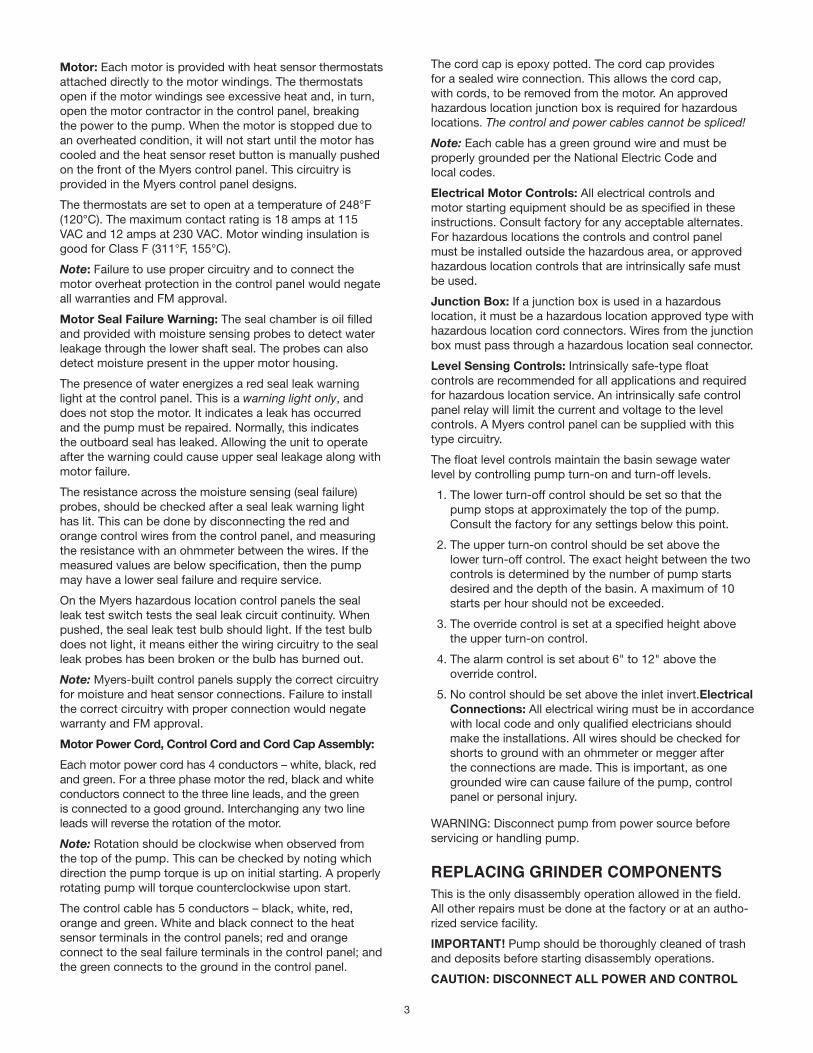
Motor: Each motor is provided with heat sensor thermostats attached directly to the motor windings. The thermostats open if the motor windings see excessive heat and, in turn, open the motor contractor in the control panel, breaking the power to the pump. When the motor is stopped due to an overheated condition, it will not start until the motor has cooled and the heat sensor reset button is manually pushed on the front of the Myers control panel. This circuitry is provided in the Myers control panel designs.
The thermostats are set to open at a temperature of 248°F (120°C). The maximum contact rating is 18 amps at 115 VAC and 12 amps at 230 VAC. Motor winding insulation is good for Class F (311°F, 155°C).
Note: Failure to use proper circuitry and to connect the motor overheat protection in the control panel would negate all warranties and FM approval.
Motor Seal Failure Warning: The seal chamber is oil filled and provided with moisture sensing probes to detect water leakage through the lower shaft seal. The probes can also detect moisture present in the upper motor housing.
The presence of water energizes a red seal leak warning light at the control panel. This is a warning light only, and does not stop the motor. It indicates a leak has occurred and the pump must be repaired. Normally, this indicates the outboard seal has leaked. Allowing the unit to operate after the warning could cause upper seal leakage along with motor failure.
The resistance across the moisture sensing (seal failure) probes, should be checked after a seal leak warning light has lit. This can be done by disconnecting the red and orange control wires from the control panel, and measuring the resistance with an ohmmeter between the wires. If the measured values are below specification, then the pump may have a lower seal failure and require service.
On the Myers hazardous location control panels the seal leak test switch tests the seal leak circuit continuity. When pushed, the seal leak test bulb should light. If the test bulb does not light, it means either the wiring circuitry to the seal leak probes has been broken or the bulb has burned out.
Note: Myers-built control panels supply the correct circuitry for moisture and heat sensor connections. Failure to install the correct circuitry with proper connection would negate warranty and FM approval.
Motor Power Cord, Control Cord and Cord Cap Assembly:Each motor power cord has 4 conductors – white, black, red and green. For a three phase motor the red, black and white conductors connect to the three line leads, and the green is connected to a good ground. Interchanging any two line leads will reverse the rotation of the motor.
Note: Rotation should be clockwise when observed from the top of the pump. This can be checked by noting which direction the pump torque is up on initial starting. A properly rotating pump will torque counterclockwise upon start.
The control cable has 5 conductors – black, white, red, orange and green. White and black connect to the heat sensor terminals in the control panels; red and orange connect to the seal failure terminals in the control panel; and the green connects to the ground in the control panel.
The cord cap is epoxy potted. The cord cap provides for a sealed wire connection. This allows the cord cap, with cords, to be removed from the motor. An approved hazardous location junction box is required for hazardous locations. The control and power cables cannot be spliced!Note: Each cable has a green ground wire and must be properly grounded per the National Electric Code and local codes.
Electrical Motor Controls: All electrical controls and motor starting equipment should be as specified in these instructions. Consult factory for any acceptable alternates. For hazardous locations the controls and control panel must be installed outside the hazardous area, or approved hazardous location controls that are intrinsically safe must be used.
Junction Box: If a junction box is used in a hazardous location, it must be a hazardous location approved type with hazardous location cord connectors. Wires from the junction box must pass through a hazardous location seal connector.
Level Sensing Controls: Intrinsically safe-type float controls are recommended for all applications and required for hazardous location service. An intrinsically safe control panel relay will limit the current and voltage to the level controls. A Myers control panel can be supplied with this type circuitry.
The float level controls maintain the basin sewage water level by controlling pump turn-on and turn-off levels.
1. The lower turn-off control should be set so that the pump stops at approximately the top of the pump. Consult the factory for any settings below this point.
2. The upper turn-on control should be set above the lower turn-off control. The exact height between the two controls is determined by the number of pump starts desired and the depth of the basin. A maximum of 10 starts per hour should not be exceeded.
3. The override control is set at a specified height above the upper turn-on control.
4. The alarm control is set about 6" to 12" above the override control.
5. No control should be set above the inlet invert.Electrical Connections: All electrical wiring must be in accordance with local code and only qualified electricians should make the installations. All wires should be checked for shorts to ground with an ohmmeter or megger after the connections are made. This is important, as one grounded wire can cause failure of the pump, control panel or personal injury.
WARNING: Disconnect pump from power source before servicing or handling pump.
REPLACING GRINDER COMPONENTSThis is the only disassembly operation allowed in the field. All other repairs must be done at the factory or at an autho-rized service facility.
IMPORTANT! Pump should be thoroughly cleaned of trash and deposits before starting disassembly operations.
CAUTION: DISCONNECT ALL POWER AND CONTROL
4
WIRES TO MOTOR AT CONTROL PANEL BEFORE STARTING DISASSEMBLY OPERATIONS. NEVER RELY ON OPENING CIRCUIT BREAKER ONLY.
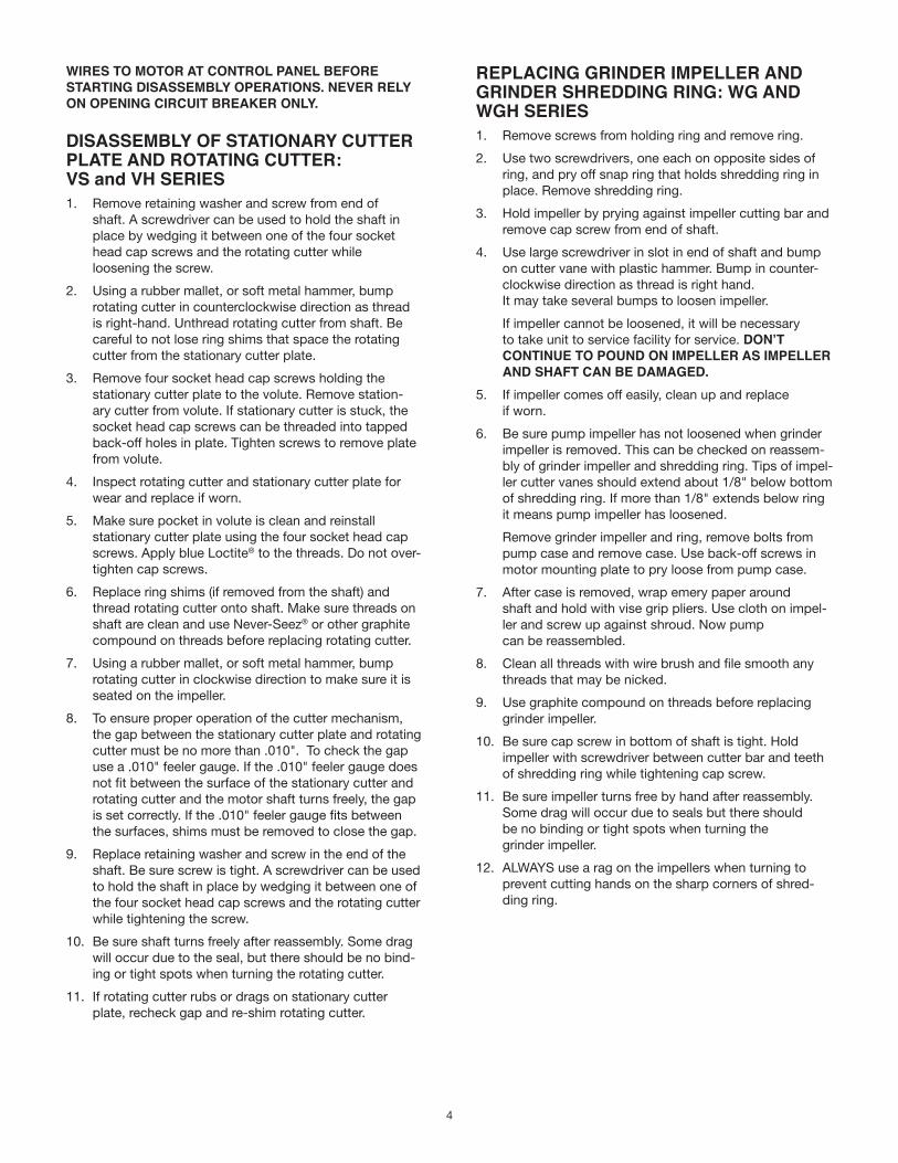
DISASSEMBLY OF STATIONARY CUTTER PLATE AND ROTATING CUTTER: VS and VH SERIES1. Remove retaining washer and screw from end of
shaft. A screwdriver can be used to hold the shaft in place by wedging it between one of the four socket head cap screws and the rotating cutter while loosening the screw.
2. Using a rubber mallet, or soft metal hammer, bump rotating cutter in counterclockwise direction as thread is right-hand. Unthread rotating cutter from shaft. Be careful to not lose ring shims that space the rotating cutter from the stationary cutter plate.
3. Remove four socket head cap screws holding the stationary cutter plate to the volute. Remove station-ary cutter from volute. If stationary cutter is stuck, the socket head cap screws can be threaded into tapped back-off holes in plate. Tighten screws to remove plate from volute.
4. Inspect rotating cutter and stationary cutter plate for wear and replace if worn.
5. Make sure pocket in volute is clean and reinstall stationary cutter plate using the four socket head cap screws. Apply blue Loctite® to the threads. Do not over-tighten cap screws.
6. Replace ring shims (if removed from the shaft) and thread rotating cutter onto shaft. Make sure threads on shaft are clean and use Never-Seez® or other graphite compound on threads before replacing rotating cutter.
7. Using a rubber mallet, or soft metal hammer, bump rotating cutter in clockwise direction to make sure it is seated on the impeller.
8. To ensure proper operation of the cutter mechanism, the gap between the stationary cutter plate and rotating cutter must be no more than .010". To check the gap use a .010" feeler gauge. If the .010" feeler gauge does not fit between the surface of the stationary cutter and rotating cutter and the motor shaft turns freely, the gap is set correctly. If the .010" feeler gauge fits between the surfaces, shims must be removed to close the gap.
9. Replace retaining washer and screw in the end of the shaft. Be sure screw is tight. A screwdriver can be used to hold the shaft in place by wedging it between one of the four socket head cap screws and the rotating cutter while tightening the screw.
10. Be sure shaft turns freely after reassembly. Some drag will occur due to the seal, but there should be no bind-ing or tight spots when turning the rotating cutter.
11. If rotating cutter rubs or drags on stationary cutter plate, recheck gap and re-shim rotating cutter.
REPLACING GRINDER IMPELLER AND GRINDER SHREDDING RING: WG AND WGH SERIES1. Remove screws from holding ring and remove ring.
2. Use two screwdrivers, one each on opposite sides of ring, and pry off snap ring that holds shredding ring in place. Remove shredding ring.
3. Hold impeller by prying against impeller cutting bar and remove cap screw from end of shaft.
4. Use large screwdriver in slot in end of shaft and bump on cutter vane with plastic hammer. Bump in counter-clockwise direction as thread is right hand. It may take several bumps to loosen impeller.
If impeller cannot be loosened, it will be necessary to take unit to service facility for service. DON’T CONTINUE TO POUND ON IMPELLER AS IMPELLER AND SHAFT CAN BE DAMAGED.
5. If impeller comes off easily, clean up and replace if worn.
6. Be sure pump impeller has not loosened when grinder impeller is removed. This can be checked on reassem-bly of grinder impeller and shredding ring. Tips of impel-ler cutter vanes should extend about 1/8" below bottom of shredding ring. If more than 1/8" extends below ring it means pump impeller has loosened.
Remove grinder impeller and ring, remove bolts from pump case and remove case. Use back-off screws in motor mounting plate to pry loose from pump case.
7. After case is removed, wrap emery paper around shaft and hold with vise grip pliers. Use cloth on impel-ler and screw up against shroud. Now pump can be reassembled.
8. Clean all threads with wire brush and file smooth any threads that may be nicked.
9. Use graphite compound on threads before replacing grinder impeller.
10. Be sure cap screw in bottom of shaft is tight. Hold impeller with screwdriver between cutter bar and teeth of shredding ring while tightening cap screw.
11. Be sure impeller turns free by hand after reassembly. Some drag will occur due to seals but there should be no binding or tight spots when turning the grinder impeller.
12. ALWAYS use a rag on the impellers when turning to prevent cutting hands on the sharp corners of shred-ding ring.
5
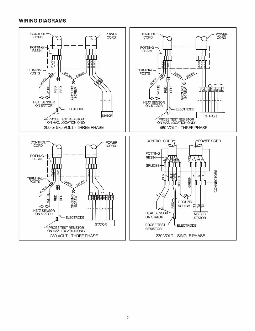
WIRING DIAGRAMS
1 2 3
POTTINGRESIN
CONTROLCORD
TERMINALPOSTS
POWERCORD
ELECTRODE
HEAT SENSORON STATOR
GR
OU
ND
SC
RE
W
RE
D
RE
D
WH
ITE
BLA
CK
BLA
CK
BLACK
RE
D
WH
ITE
GREENGREEN
PROBE TEST RESISTORON HAZ. LOCATION ONLY
STATOR
AB
0 0
200 or 575 VOLT - THREE PHASE
1 2 3
BLA
CK
BLA
CK
1 7 2 8 3 9 4 5 6
POTTINGRESIN
CONTROLCORD
TERMINALPOSTS
POWERCORD
ELECTRODE
HEAT SENSORON STATOR
GR
OU
ND
SC
RE
W
RE
D
RE
D
WH
ITE
BLA
CK
BLA
CK
BLACK
RE
D
WH
ITE
GREENGREEN
PROBE TEST RESISTORON HAZ. LOCATION ONLY
STATOR
AB
0 0
230 VOLT - THREE PHASE
1
7
2
6
5
4
8
3
9
230 VOLT – SINGLE PHASE
CONTROL CORD POWER CORD
POTTINGRESIN
SPLICES
HEAT SENSORON STATOR
PROBE TESTRESISTOR
ELECTRODE
GROUNDSCREW
MOTORSTATOR
CO
NN
EC
TOR
S
T1
T2 T3
RE
D
GR
EE
N
GR
EE
NBLK Y
RE
DR
ED
P1 P2
Y B R
Y B RGR
N
GR
NO
RN
RE
DYBL
K
1 72 83 9 456
POTTINGRESIN
CONTROLCORD
TERMINALPOSTS
POWERCORD
ELECTRODE
HEAT SENSORON STATOR
GR
OU
ND
SC
RE
W
RE
D
RE
D
WH
ITE
BLA
CK
BLA
CK
BLACK
RE
D
WH
ITE
GREENGREEN
PROBE TEST RESISTORON HAZ. LOCATION ONLY
STATOR
AB
0 0
460 VOLT - THREE PHASE
1
2
3
7
4
8
4
9
5
BLA
CK
BLA
CK
6
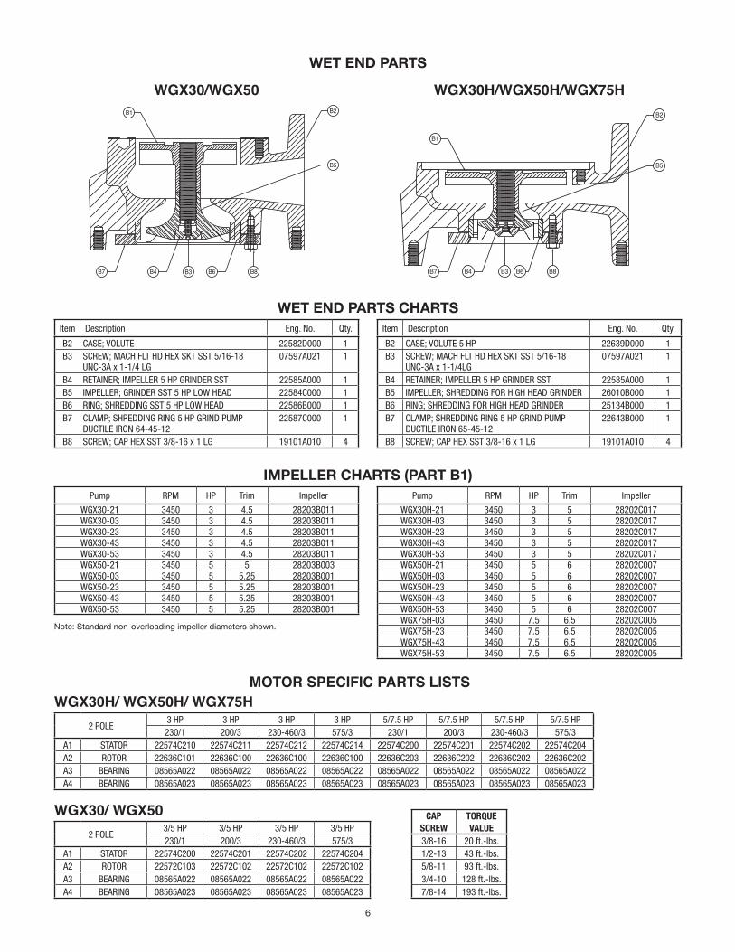
WET END PARTS
WET END PARTS CHARTSItem Description Eng. No. Qty.
B2 CASE; VOLUTE 22582D000 1B3 SCREW; MACH FLT HD HEX SKT SST 5/16-18
UNC-3A x 1-1/4 LG07597A021 1
B4 RETAINER; IMPELLER 5 HP GRINDER SST 22585A000 1B5 IMPELLER; GRINDER SST 5 HP LOW HEAD 22584C000 1B6 RING; SHREDDING SST 5 HP LOW HEAD 22586B000 1B7 CLAMP; SHREDDING RING 5 HP GRIND PUMP
DUCTILE IRON 64-45-1222587C000 1
B8 SCREW; CAP HEX SST 3/8-16 x 1 LG 19101A010 4
Item Description Eng. No. Qty.
B2 CASE; VOLUTE 5 HP 22639D000 1B3 SCREW; MACH FLT HD HEX SKT SST 5/16-18
UNC-3A x 1-1/4LG07597A021 1
B4 RETAINER; IMPELLER 5 HP GRINDER SST 22585A000 1B5 IMPELLER; SHREDDING FOR HIGH HEAD GRINDER 26010B000 1B6 RING; SHREDDING FOR HIGH HEAD GRINDER 25134B000 1B7 CLAMP; SHREDDING RING 5 HP GRIND PUMP
DUCTILE IRON 65-45-1222643B000 1
B8 SCREW; CAP HEX SST 3/8-16 x 1 LG 19101A010 4
IMPELLER CHARTS (PART B1)
Note: Standard non-overloading impeller diameters shown.
Pump RPM HP Trim Impeller
WGX30H-21 3450 3 5 28202C017WGX30H-03 3450 3 5 28202C017WGX30H-23 3450 3 5 28202C017WGX30H-43 3450 3 5 28202C017WGX30H-53 3450 3 5 28202C017WGX50H-21 3450 5 6 28202C007WGX50H-03 3450 5 6 28202C007WGX50H-23 3450 5 6 28202C007WGX50H-43 3450 5 6 28202C007WGX50H-53 3450 5 6 28202C007WGX75H-03 3450 7.5 6.5 28202C005WGX75H-23 3450 7.5 6.5 28202C005WGX75H-43 3450 7.5 6.5 28202C005WGX75H-53 3450 7.5 6.5 28202C005
Pump RPM HP Trim Impeller
WGX30-21 3450 3 4.5 28203B011WGX30-03 3450 3 4.5 28203B011WGX30-23 3450 3 4.5 28203B011WGX30-43 3450 3 4.5 28203B011WGX30-53 3450 3 4.5 28203B011WGX50-21 3450 5 5 28203B003WGX50-03 3450 5 5.25 28203B001WGX50-23 3450 5 5.25 28203B001WGX50-43 3450 5 5.25 28203B001WGX50-53 3450 5 5.25 28203B001
WGX30/WGX50 WGX30H/WGX50H/WGX75HB2
B5
B1
B4B7 B6 B8B3
B1
B2
B5
B4B7 B6 B8B3
MOTOR SPECIFIC PARTS LISTS
2 POLE3 HP 3 HP 3 HP 3 HP 5/7.5 HP 5/7.5 HP 5/7.5 HP 5/7.5 HP230/1 200/3 230-460/3 575/3 230/1 200/3 230-460/3 575/3
A1 STATOR 22574C210 22574C211 22574C212 22574C214 22574C200 22574C201 22574C202 22574C204A2 ROTOR 22636C101 22636C100 22636C100 22636C100 22636C203 22636C202 22636C202 22636C202A3 BEARING 08565A022 08565A022 08565A022 08565A022 08565A022 08565A022 08565A022 08565A022A4 BEARING 08565A023 08565A023 08565A023 08565A023 08565A023 08565A023 08565A023 08565A023
WGX30H/ WGX50H/ WGX75H
CAP SCREW
TORQUE VALUE
3/8-16 20 ft.-lbs.1/2-13 43 ft.-lbs.5/8-11 93 ft.-lbs.3/4-10 128 ft.-lbs.7/8-14 193 ft.-lbs.
2 POLE3/5 HP 3/5 HP 3/5 HP 3/5 HP230/1 200/3 230-460/3 575/3
A1 STATOR 22574C200 22574C201 22574C202 22574C204A2 ROTOR 22572C103 22572C102 22572C102 22572C102A3 BEARING 08565A022 08565A022 08565A022 08565A022A4 BEARING 08565A023 08565A023 08565A023 08565A023
WGX30/ WGX50
7
B2
B6B8B7
B5B3
B4
B1
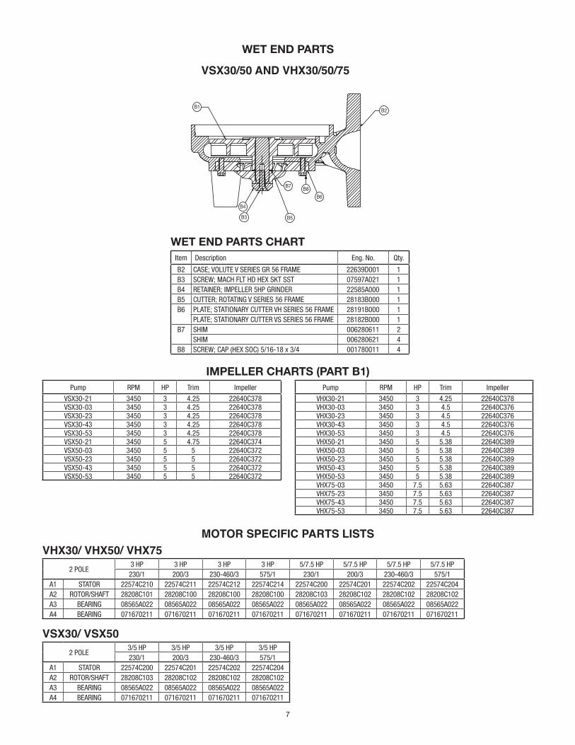
WET END PARTS
IMPELLER CHARTS (PART B1)Pump RPM HP Trim Impeller
VHX30-21 3450 3 4.25 22640C378VHX30-03 3450 3 4.5 22640C376VHX30-23 3450 3 4.5 22640C376VHX30-43 3450 3 4.5 22640C376VHX30-53 3450 3 4.5 22640C376VHX50-21 3450 5 5.38 22640C389VHX50-03 3450 5 5.38 22640C389VHX50-23 3450 5 5.38 22640C389VHX50-43 3450 5 5.38 22640C389VHX50-53 3450 5 5.38 22640C389VHX75-03 3450 7.5 5.63 22640C387VHX75-23 3450 7.5 5.63 22640C387VHX75-43 3450 7.5 5.63 22640C387VHX75-53 3450 7.5 5.63 22640C387
Pump RPM HP Trim Impeller
VSX30-21 3450 3 4.25 22640C378VSX30-03 3450 3 4.25 22640C378VSX30-23 3450 3 4.25 22640C378VSX30-43 3450 3 4.25 22640C378VSX30-53 3450 3 4.25 22640C378VSX50-21 3450 5 4.75 22640C374VSX50-03 3450 5 5 22640C372VSX50-23 3450 5 5 22640C372VSX50-43 3450 5 5 22640C372VSX50-53 3450 5 5 22640C372
VSX30/50 AND VHX30/50/75
WET END PARTS CHARTItem Description Eng. No. Qty.
B2 CASE; VOLUTE V SERIES GR 56 FRAME 22639D001 1B3 SCREW; MACH FLT HD HEX SKT SST 07597A021 1B4 RETAINER; IMPELLER 5HP GRINDER 22585A000 1B5 CUTTER; ROTATING V SERIES 56 FRAME 28183B000 1B6 PLATE; STATIONARY CUTTER VH SERIES 56 FRAME 28191B000 1
PLATE; STATIONARY CUTTER VS SERIES 56 FRAME 28182B000 1B7 SHIM 006280611 2
SHIM 006280621 4B8 SCREW; CAP (HEX SOC) 5/16-18 x 3/4 001780011 4
MOTOR SPECIFIC PARTS LISTS
2 POLE3 HP 3 HP 3 HP 3 HP 5/7.5 HP 5/7.5 HP 5/7.5 HP 5/7.5 HP230/1 200/3 230-460/3 575/1 230/1 200/3 230-460/3 575/1
A1 STATOR 22574C210 22574C211 22574C212 22574C214 22574C200 22574C201 22574C202 22574C204A2 ROTOR/SHAFT 28208C101 28208C100 28208C100 28208C100 28208C103 28208C102 28208C102 28208C102A3 BEARING 08565A022 08565A022 08565A022 08565A022 08565A022 08565A022 08565A022 08565A022A4 BEARING 071670211 071670211 071670211 071670211 071670211 071670211 071670211 071670211
VHX30/ VHX50/ VHX75
2 POLE3/5 HP 3/5 HP 3/5 HP 3/5 HP230/1 200/3 230-460/3 575/1
A1 STATOR 22574C200 22574C201 22574C202 22574C204A2 ROTOR/SHAFT 28208C103 28208C102 28208C102 28208C102A3 BEARING 08565A022 08565A022 08565A022 08565A022A4 BEARING 071670211 071670211 071670211 071670211
VSX30/ VSX50
8
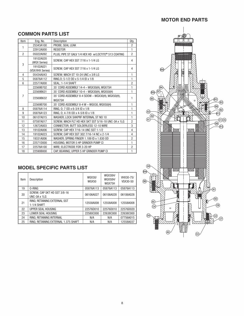
COMMON PARTS LISTItem Eng. No. Description Qty.
125343A100 PROBE; SEAL LEAK 222912A000 RESISTOR 1
2 05022A092 PLUG; PIPE ST GALV 1/4 HEX HD w/LOCTITE® 513 COATING 2
3
19102A020 (WGX Series)
SCREW; CAP HEX SST 7/16 x 1-1/4 LG 4
19102A021 (VSX/VHX Series)
SCREW; CAP HEX SST 7/16 x 1-1/4 LG 4
4 05434A043 SCREW; MACH ST 10-24 UNC x 3/8 LG 15 05876A112 RING,O; 5-1/2 OD x 5-1/4 ID x 1/8 16 22577A000 SEAL; 1-1/4 SHAFT 2
7
22569B702 35' CORD ASSEMBLY 14-4 – WGX30(H), WGX75H 122569B631 35' CORD ASSEMBLY 10-4 – WGX30(H), WGX50(H) 1
22569B63235' CORD ASSEMBLY 8-4 SOOW – WGX30(H), WGX50(H), WGX75H
1
22569B700 35' CORD ASSEMBLY 8-4 W – WGX30, WGX50(H) 18 05876A114 RING, O; 7 OD x 6-3/4 ID x 1/8 19 05876A123 RING, O; 4-7/8 OD x 4-5/8 ID x 1/8 1
10 06107A015 WASHER; LOCK SHKPRF INTERNAL ST NO 10 111 07597A017 SCREW; MACH FLT HD HEX SKT SST 5/16-18 UNC-3A x 1LG 212 12672A003 CONNECTOR; BUTT SOLDERLESS 12-10 WIRE 313 19102A006 SCREW; CAP HEX 7/16-14 UNC SST 1-1/2 414 19102A023 SCREW; CAP HEX SST 302 7/16-14 NC x 2-1/4 415 19331A006 WASHER; SPRING FINGER 1.189 ID x 1.830 OD 216 22571D000 HOUSING; MOTOR 5 HP GRINDER PUMP CI 117 22578A100 WIRE; ELECTRODE FOR 3-20 HP 218 22590B000 CAP, BEARING; UPPER 5 HP GRINDER PUMP CI 1
MODEL SPECIFIC PARTS LIST
Item DescriptionWGX30/ WGX50
WGX30H/WGX50H/WGX75H
VHX30-75/ VSX30-50
19 O-RING 05876A113 05876A113 05876A113
20SCREW; CAP SKT HD SST 3/8-16 UNC-3A x 1LG
06106A027 06106A028 06106A028
21RING; RETAINING EXTERNAL SST 1-1/4 SHAFT
12558A008 12558A008 12558A008
22 UPPER SEAL HOUSING 22576D010 22576D010 22576D02023 LOWER SEAL HOUSING 22580C000 22638C000 22638C00024 RING; RETAINING INTERNAL N/A N/A 07756A01525 RING; RETAINING EXTERNAL 1.375 SHAFT N/A N/A 12558A037
MOTOR END PARTS
B4
B15
B5
A3
A2A1
A4
B14
D4
B6
A5
C4
A5C3
C7C2
C6
B2
B1
B12B8
C1
B9
B3B11
B2B13
C5
B7
B10
9
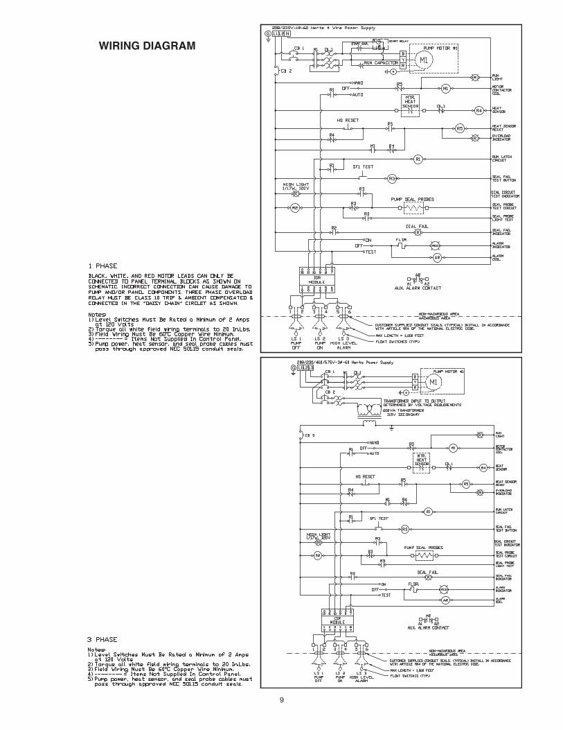
WIRING DIAGRAM
10
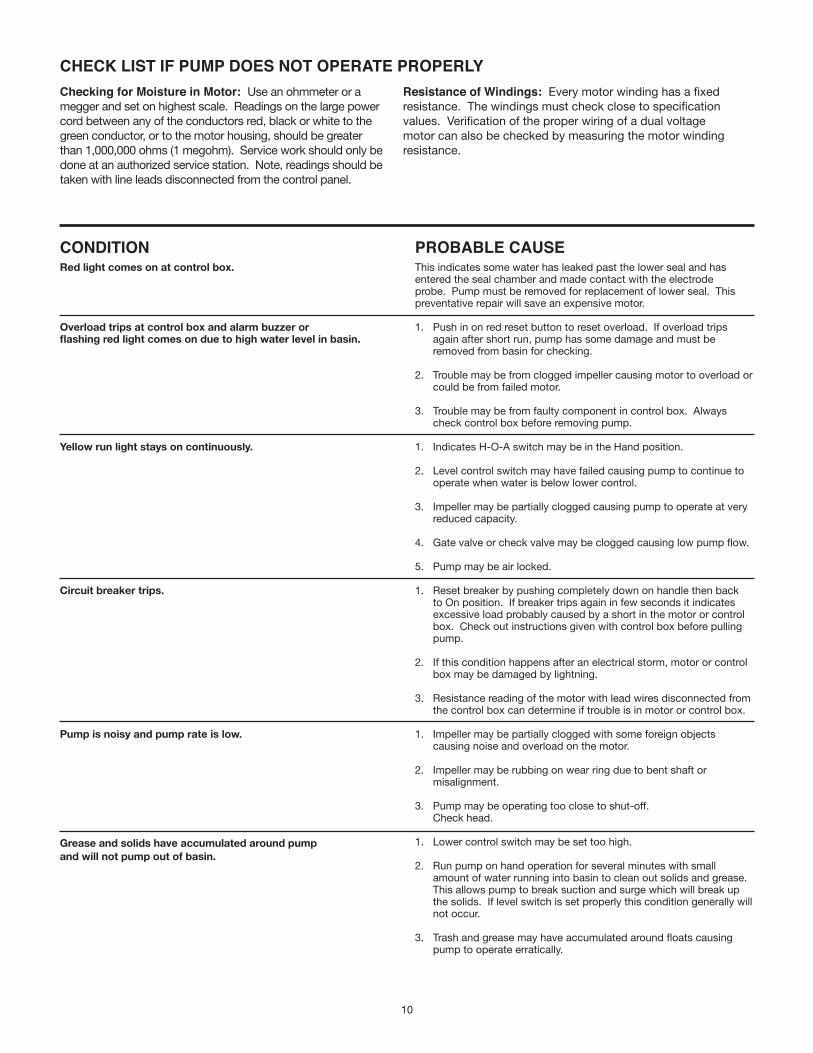
CHECK LIST IF PUMP DOES NOT OPERATE PROPERLYChecking for Moisture in Motor: Use an ohmmeter or a megger and set on highest scale. Readings on the large power cord between any of the conductors red, black or white to the green conductor, or to the motor housing, should be greater than 1,000,000 ohms (1 megohm). Service work should only be done at an authorized service station. Note, readings should be taken with line leads disconnected from the control panel.
Resistance of Windings: Every motor winding has a fixed resistance. The windings must check close to specification values. Verification of the proper wiring of a dual voltage motor can also be checked by measuring the motor winding resistance.
CONDITIONRed light comes on at control box.
Overload trips at control box and alarm buzzer or flashing red light comes on due to high water level in basin.
Yellow run light stays on continuously.
Circuit breaker trips.
Pump is noisy and pump rate is low.
Grease and solids have accumulated around pump and will not pump out of basin.
PROBABLE CAUSEThis indicates some water has leaked past the lower seal and has entered the seal chamber and made contact with the electrode probe. Pump must be removed for replacement of lower seal. This preventative repair will save an expensive motor.
1. Push in on red reset button to reset overload. If overload trips again after short run, pump has some damage and must be removed from basin for checking.
2. Trouble may be from clogged impeller causing motor to overload or could be from failed motor.
3. Trouble may be from faulty component in control box. Always check control box before removing pump.
1. Indicates H-O-A switch may be in the Hand position.
2. Level control switch may have failed causing pump to continue to operate when water is below lower control.
3. Impeller may be partially clogged causing pump to operate at very reduced capacity.
4. Gate valve or check valve may be clogged causing low pump flow.
5. Pump may be air locked.
1. Reset breaker by pushing completely down on handle then back to On position. If breaker trips again in few seconds it indicates excessive load probably caused by a short in the motor or control box. Check out instructions given with control box before pulling pump.
2. If this condition happens after an electrical storm, motor or control box may be damaged by lightning.
3. Resistance reading of the motor with lead wires disconnected from the control box can determine if trouble is in motor or control box.
1. Impeller may be partially clogged with some foreign objects causing noise and overload on the motor.
2. Impeller may be rubbing on wear ring due to bent shaft or misalignment.
3. Pump may be operating too close to shut-off. Check head.
1. Lower control switch may be set too high.
2. Run pump on hand operation for several minutes with small amount of water running into basin to clean out solids and grease. This allows pump to break suction and surge which will break up the solids. If level switch is set properly this condition generally will not occur.
3. Trash and grease may have accumulated around floats causing pump to operate erratically.

11
1101 MYERS PARKWAY 490 PINEBUSH ROAD, UNIT #4 ASHLAND, OHIO, USA 44805 CAMBRIDGE, ONTARIO, CANADA N1T 0A5 419-289-1144 800-363-PUMP
WWW.FEMYERS.COM
Warranty Rev. 04/17
V AND VR SERIES LIMITED WARRANTY
Pentair Myers® warrants its V and VR series grinders against defects in material and workmanship for a period of 24 months from the manufacturing date, or 36 months from the manufacturing date with completion of a start-up report within 30 days of installation. Product must be properly installed, serviced and operated in compliance with the manufacturer’s instruction manuals.
During the warranty period and subject to the conditions set forth, Pentair Myers, at its discretion, will repair or replace to the original user, the parts that prove defective in materials and workmanship. Pentair Myers reserves the right to change or improve its products or any portions thereof without being obligated to provide such a change or improvement for prior sold and/or shipped units.
Start-up reports and electrical schematics may be required to support warranty claims. Submit at the time of start- up through the Pentair Myers website: http://forms.pentairliterature.com/startupform/startupform.asp?type=m. All seal fail and heat sensing devices must be connected, functional and monitored or this warranty will be void. Pentair Myers will cover only the lower seal and labor thereof for all dual seal pumps. Under no circumstance will Pentair Myers be responsible for the cost of field labor, travel expenses, rented equipment, removal/reinstallation costs or freight expenses to and from the factory or an authorized Pentair Myers service facility.
This limited warranty will not apply:a) To defects or malfunctions resulting from failure to properly install, operate or maintain the unit in accordance with the
printed instructions provided; b) To failures resulting from abuse, accident or negligence; c) To failures resulting from excessive sand, lime, cement, gravel or other abrasive materialsd) To failures caused by scale or corrosion build-up due to excessive hydrocarbons or chemical contente) To normal maintenance services and parts used in connection with such service; f) To units that are not installed in accordance with applicable local codes, ordinances and good trade practices; g) If the unit is moved from its original installation location; h) If unit is used for purposes other than for what it is designed and manufactured; i) To any unit that has been repaired or altered by anyone other than Pentair Myers or an authorized Pentair Myers service
provider; j) To any unit that has been repaired using non factory specified/OEM parts.
Warranty Exclusions: PENTAIR MYERS MAKES NO EXPRESS OR IMPLIED WARRANTIES THAT EXTEND BEYOND THE DESCRIPTION ON THE FACE HEREOF. PENTAIR MYERS SPECIFICALLY DISCLAIMS THE IMPLIED WARRANTIES OF MERCHANTABILITY AND FITNESS FOR ANY PARTICULAR PURPOSE.
Liability Limitation: IN NO EVENT SHALL PENTAIR MYERS BE LIABLE OR RESPONSIBLE FOR CONSEQUENTIAL, INCIDENTAL OR SPECIAL DAMAGES RESULTING FROM OR RELATED IN ANY MANNER TO ANY PENTAIR MYERS PRODUCT OR PARTS THEREOF. PERSONAL INJURY AND/OR PROPERTY DAMAGE MAY RESULT FROM IMPROPER INSTALLATION. PENTAIR MYERS DISCLAIMS ALL LIABILITY, INCLUDING LIABILITY UNDER THIS WARRANTY, FOR IMPROPER INSTALLATION. PENTAIR MYERS RECOMMENDS INSTALLATION BY PROFESSIONALS.
Some states do not permit some or all of the above warranty limitations or the exclusion or limitation of incidental or consequential damages and therefore such limitations may not apply to you. no warranties or representations at any time made by any representatives of Pentair Myers shall vary or expand the provision hereof.

Warranty Rev. 12/13
STANDARD LIMITED WARRANTY
Pentair Myers® warrants its products against defects in material and workmanship for a period of 12 months from the date of shipment from Pentair Myers or 18 months from the manufacturing date, whichever occurs first – provided that such products are used in compliance with the requirements of the Pentair Myers catalog and technical manuals for use in pumping raw sewage, municipal wastewater or similar, abrasive-free, noncorrosive liquids.
During the warranty period and subject to the conditions set forth, Pentair Myers, at its discretion, will repair or replace to the original user, the parts that prove defective in materials and workmanship. Pentair Myers reserves the right to change or improve its products or any portions thereof without being obligated to provide such a change or improvement for prior sold and/or shipped units.
Start-up reports and electrical schematics may be required to support warranty claims. Submit at the time of start- up through the Pentair Myers website: http://forms.pentairliterature.com/startupform/startupform.asp?type=m. Warranty is effective only if Pentair Myers authorized control panels are used. All seal fail and heat sensing devices must be hooked up, functional and monitored or this warranty will be void. Pentair Myers will cover only the lower seal and labor thereof for all dual seal pumps. Under no circumstance will Pentair Myers be responsible for the cost of field labor, travel expenses, rented equipment, removal/reinstallation costs or freight expenses to and from the factory or an authorized Pentair Myers service facility.
This limited warranty will not apply: (a) to defects or malfunctions resulting from failure to properly install, operate or maintain the unit in accordance with the printed instructions provided; (b) to failures resulting from abuse, accident or negligence; (c) to normal maintenance services and parts used in connection with such service; (d) to units that are not installed in accordance with applicable local codes, ordinances and good trade practices; (e) if the unit is moved from its original installation location; (f) if unit is used for purposes other than for what it is designed and manufactured; (g) to any unit that has been repaired or altered by anyone other than Pentair Myers or an authorized Pentair Myers service provider; (h) to any unit that has been repaired using non factory specified/OEM parts.
Warranty Exclusions: PENTAIR MYERS MAKES NO EXPRESS OR IMPLIED WARRANTIES THAT EXTEND BEYOND THE DESCRIPTION ON THE FACE HEREOF. PENTAIR MYERS SPECIFICALLY DISCLAIMS THE IMPLIED WARRANTIES OF MERCHANTABILITY AND FITNESS FOR ANY PARTICULAR PURPOSE.
Liability Limitation: IN NO EVENT SHALL PENTAIR MYERS BE LIABLE OR RESPONSIBLE FOR CONSEQUENTIAL, INCIDENTAL OR SPECIAL DAMAGES RESULTING FROM OR RELATED IN ANY MANNER TO ANY PENTAIR MYERS PRODUCT OR PARTS THEREOF. PERSONAL INJURY AND/OR PROPERTY DAMAGE MAY RESULT FROM IMPROPER INSTALLATION. PENTAIR MYERS DISCLAIMS ALL LIABILITY, INCLUDING LIABILITY UNDER THIS WARRANTY, FOR IMPROPER INSTALLATION. PENTAIR MYERS RECOMMENDS INSTALLATION BY PROFESSIONALS.
Some states do not permit some or all of the above warranty limitations or the exclusion or limitation of incidental or consequential damages and therefore such limitations may not apply to you. No warranties or representations at any time made by any representatives of Pentair Myers shall vary or expand the provision hereof.
1101 MYERS PARKWAY 490 PINEBUSH ROAD, UNIT 4ASHLAND, OHIO 44805 CAMBRIDGE, ONTARIO, CANADA N1T 0A5PH: 855-274-8947 PH: 800-363-7867WWW.FEMYERS.COM WWW.FEMYERS.COM