Embed Size (px)
Citation preview

MODERN ADVANCES IN COMPUTATIONAL IMAGING AT MICROWAVE AND MILLIMETRE-WAVE FREQUENCIES
Okan Yurduseven#1, Thomas Fromentèze#2
#1Queen’s University Belfast, UK
#2Xlim Research Institute, University of Limoges, France
[email protected], [email protected]
STh-01
New advances in computational imaging:Polarimetric imaging, phaseless imaging, and recent advances in antenna systemsand k-space reconstruction techniques
Okan Yurduseven#1, Thomas Fromenteze#2
#1Queen’s University Belfast, UK
#2Xlim Research Institute, University of Limoges, France
[email protected], [email protected]
STh-01
- 3 -STh-01
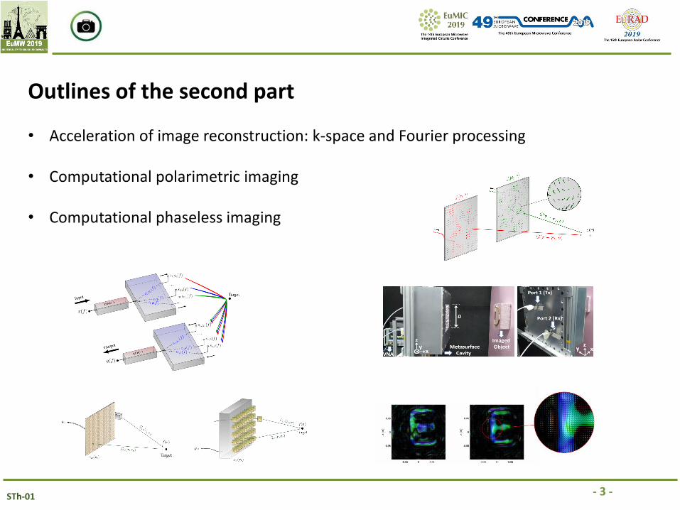
Outlines of the second part
• Acceleration of image reconstruction: k-space and Fourier processing
• Computational polarimetric imaging
• Computational phaseless imaging
- 4 -STh-01
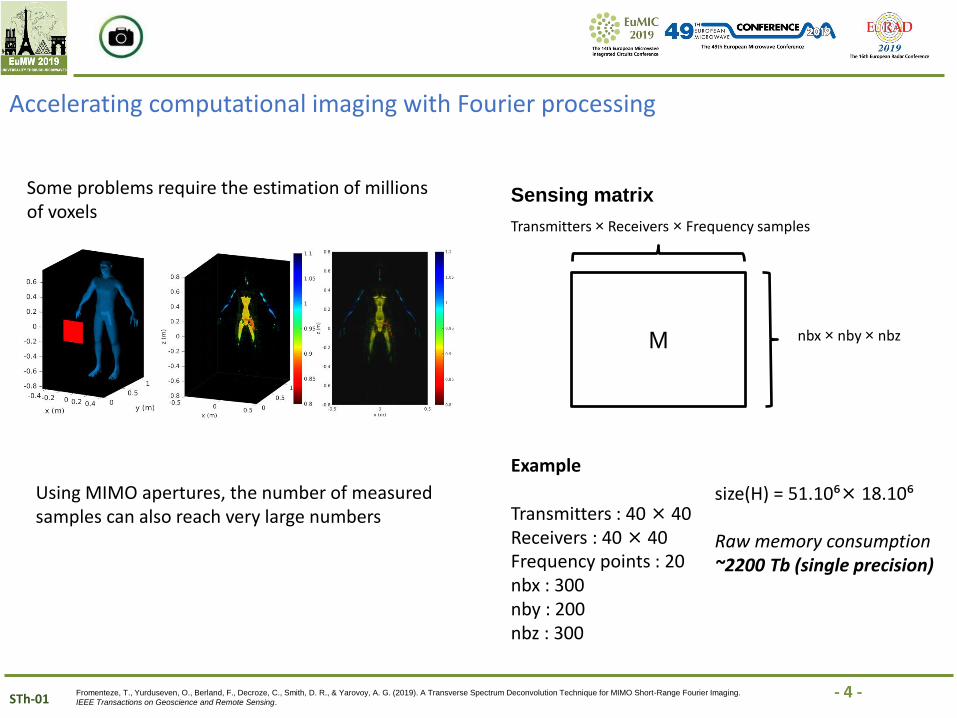
Accelerating computational imaging with Fourier processing
Some problems require the estimation of millions of voxels
Fromenteze, T., Yurduseven, O., Berland, F., Decroze, C., Smith, D. R., & Yarovoy, A. G. (2019). A Transverse Spectrum Deconvolution Technique for MIMO Short-Range Fourier Imaging.
IEEE Transactions on Geoscience and Remote Sensing.
Using MIMO apertures, the number of measured samples can also reach very large numbers
M
Transmitters × Receivers × Frequency samples
nbx × nby × nbz
Sensing matrix
Example
Transmitters : 40× 40Receivers : 40 × 40Frequency points : 20nbx : 300nby : 200nbz : 300
size(H) = 51.10⁶× 18.10⁶
Raw memory consumption ~2200 Tb (single precision)
- 5 -STh-01
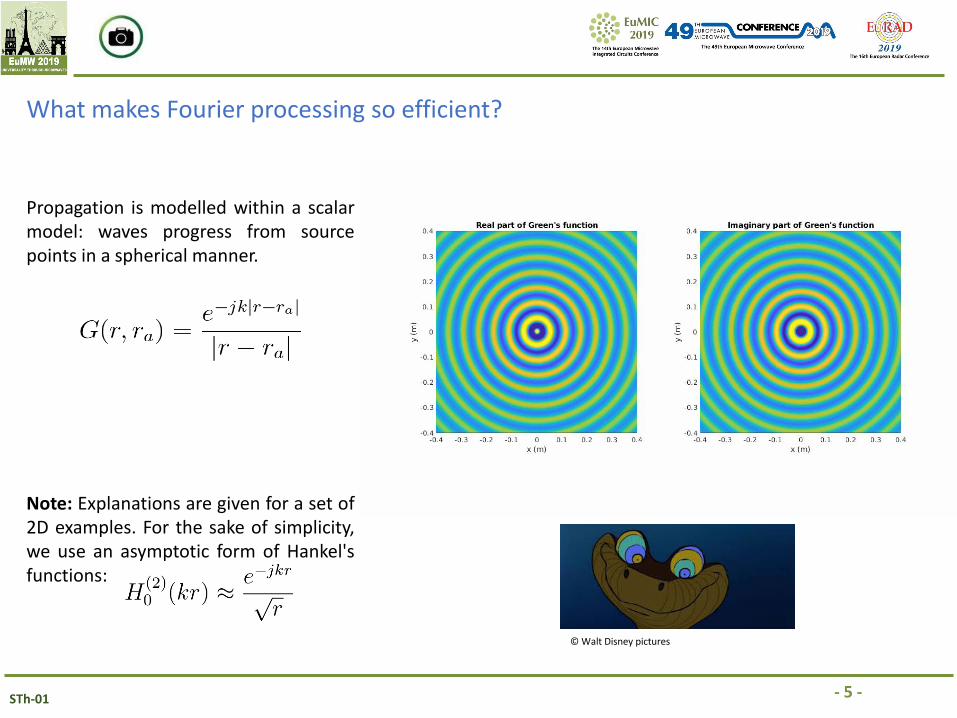
What makes Fourier processing so efficient?
Note: Explanations are given for a set of2D examples. For the sake of simplicity,we use an asymptotic form of Hankel'sfunctions:
Propagation is modelled within a scalarmodel: waves progress from sourcepoints in a spherical manner.
© Walt Disney pictures
- 6 -STh-01
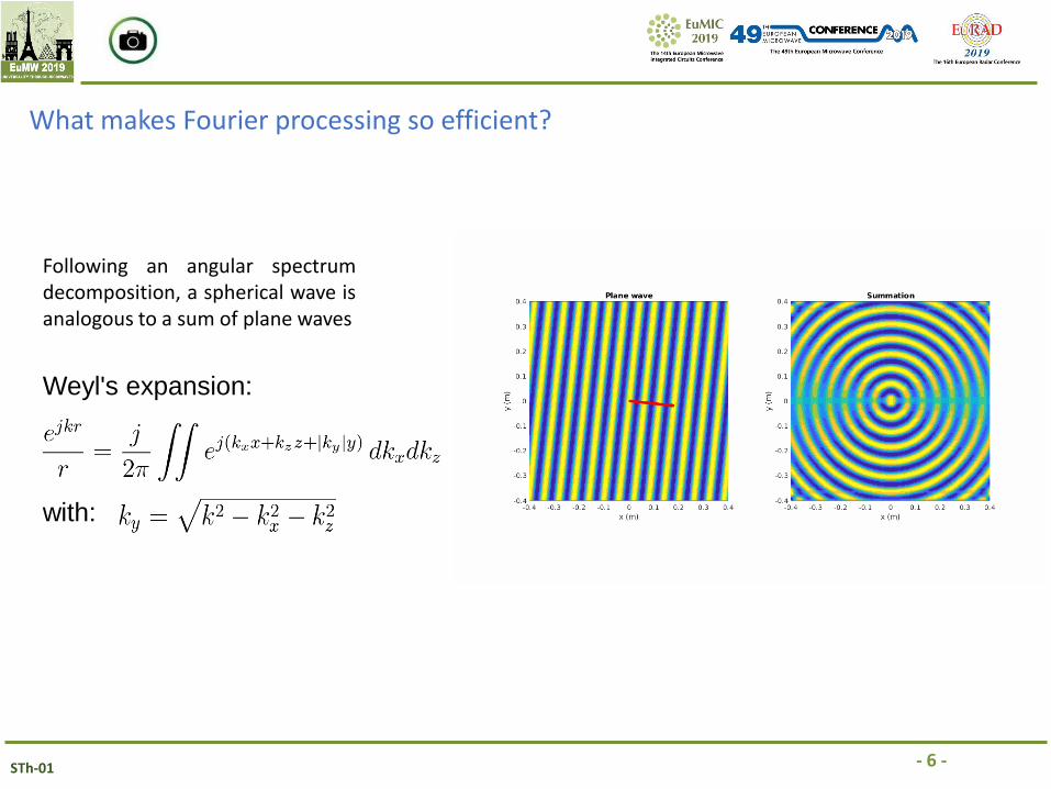
Weyl's expansion:
with:
Following an angular spectrumdecomposition, a spherical wave isanalogous to a sum of plane waves
What makes Fourier processing so efficient?
- 7 -STh-01
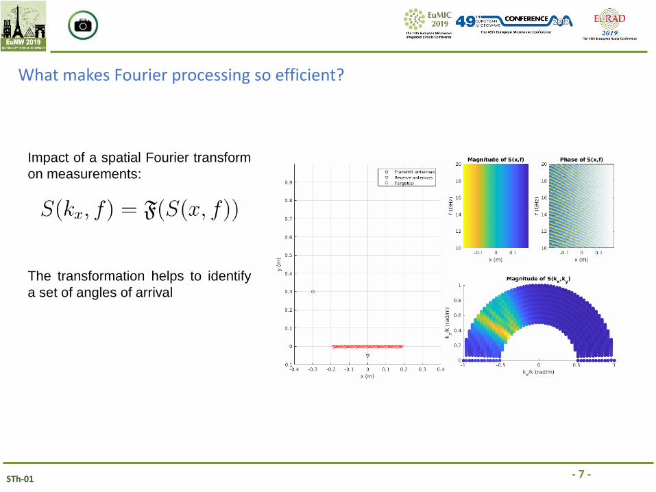
Impact of a spatial Fourier transform
on measurements:
The transformation helps to identify
a set of angles of arrival
What makes Fourier processing so efficient?
- 8 -STh-01
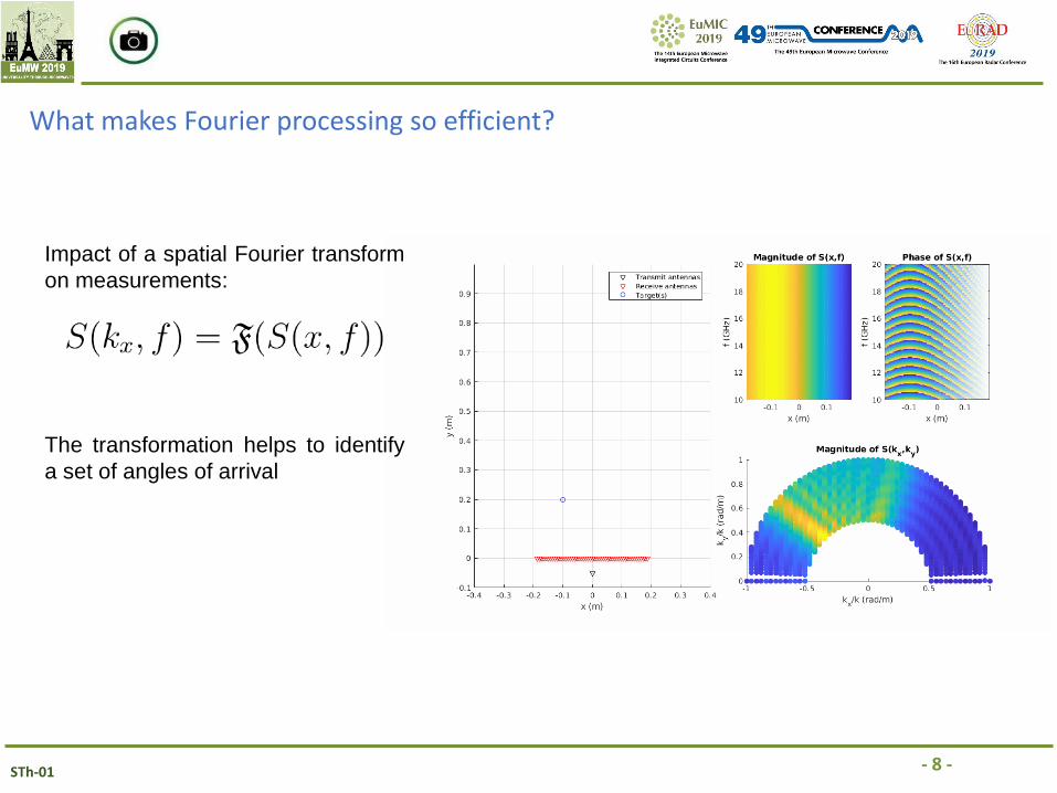
Impact of a spatial Fourier transform
on measurements:
The transformation helps to identify
a set of angles of arrival
What makes Fourier processing so efficient?
- 9 -STh-01
What makes Fourier processing so efficient?
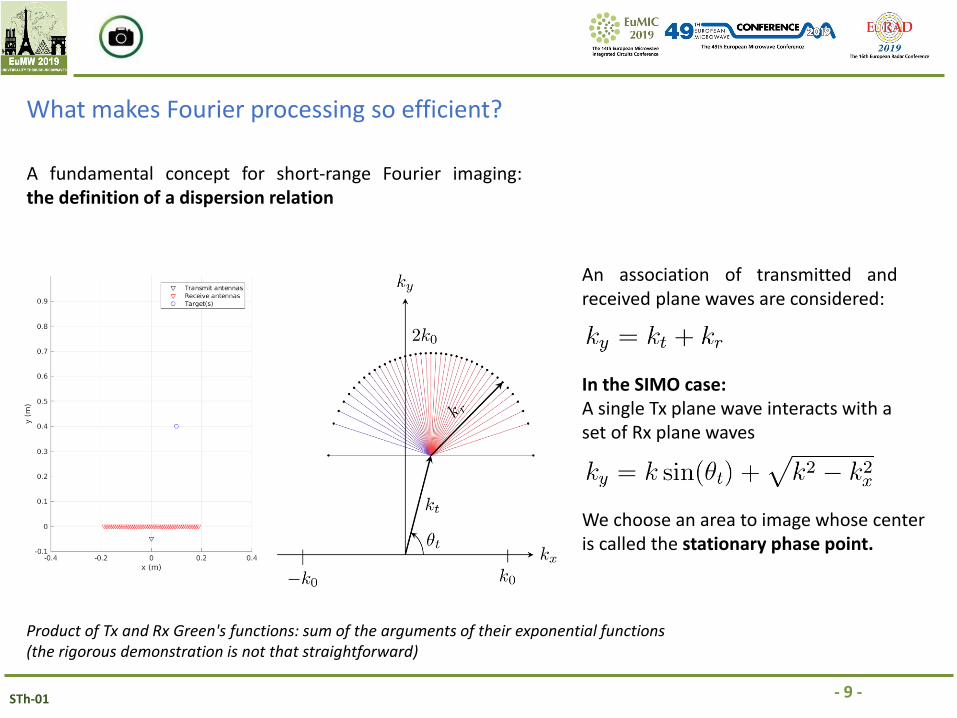
A fundamental concept for short-range Fourier imaging:the definition of a dispersion relation
An association of transmitted andreceived plane waves are considered:
Product of Tx and Rx Green's functions: sum of the arguments of their exponential functions(the rigorous demonstration is not that straightforward)
In the SIMO case:A single Tx plane wave interacts with a set of Rx plane waves
We choose an area to image whose center is called the stationary phase point.
- 10 -STh-01
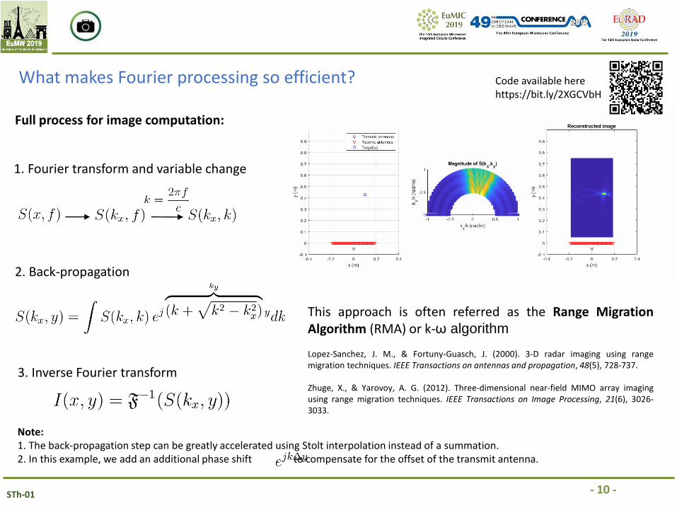
What makes Fourier processing so efficient?
Full process for image computation:
1. Fourier transform and variable change
2. Back-propagation
3. Inverse Fourier transform
Note:1. The back-propagation step can be greatly accelerated using Stolt interpolation instead of a summation.2. In this example, we add an additional phase shift to compensate for the offset of the transmit antenna.
This approach is often referred as the Range MigrationAlgorithm (RMA) or k-ω algorithm
Lopez-Sanchez, J. M., & Fortuny-Guasch, J. (2000). 3-D radar imaging using rangemigration techniques. IEEE Transactions on antennas and propagation, 48(5), 728-737.
Zhuge, X., & Yarovoy, A. G. (2012). Three-dimensional near-field MIMO array imagingusing range migration techniques. IEEE Transactions on Image Processing, 21(6), 3026-3033.
Code available herehttps://bit.ly/2XGCVbH
- 11 -STh-01
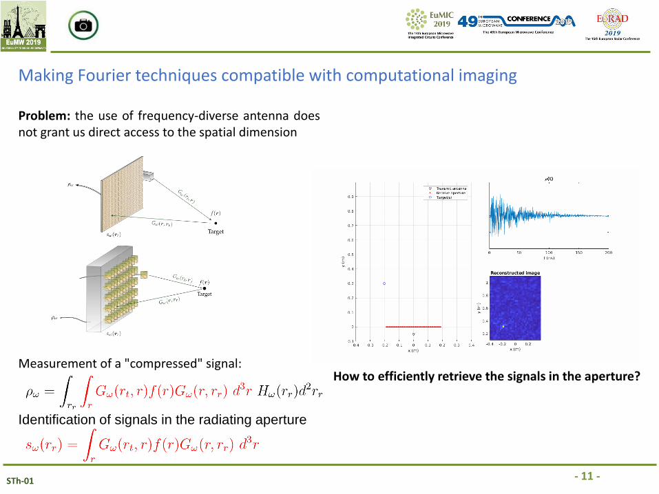
Making Fourier techniques compatible with computational imaging
Problem: the use of frequency-diverse antenna doesnot grant us direct access to the spatial dimension
Measurement of a "compressed" signal:
Identification of signals in the radiating aperture
How to efficiently retrieve the signals in the aperture?
- 12 -STh-01
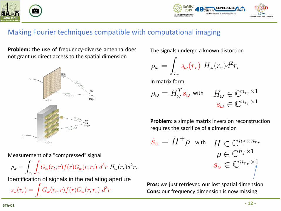
Making Fourier techniques compatible with computational imaging
Problem: the use of frequency-diverse antenna doesnot grant us direct access to the spatial dimension
Measurement of a "compressed" signal
Identification of signals in the radiating aperture
The signals undergo a known distortion
In matrix form
with
Problem: a simple matrix inversion reconstructionrequires the sacrifice of a dimension
with
Pros: we just retrieved our lost spatial dimensionCons: our frequency dimension is now missing
- 13 -STh-01
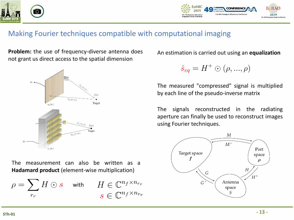
Making Fourier techniques compatible with computational imaging
Problem: the use of frequency-diverse antenna doesnot grant us direct access to the spatial dimension
An estimation is carried out using an equalization
The measurement can also be written as aHadamard product (element-wise multiplication)
with
The measured "compressed" signal is multipliedby each line of the pseudo-inverse matrix
The signals reconstructed in the radiatingaperture can finally be used to reconstruct imagesusing Fourier techniques.
- 14 -STh-01
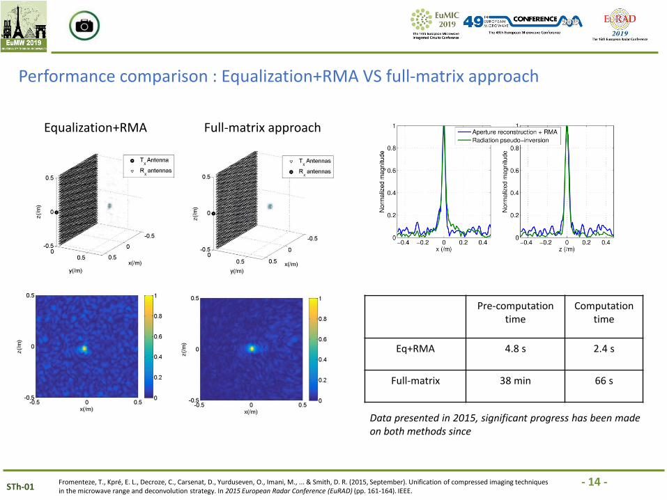
Performance comparison : Equalization+RMA VS full-matrix approach
Fromenteze, T., Kpré, E. L., Decroze, C., Carsenat, D., Yurduseven, O., Imani, M., ... & Smith, D. R. (2015, September). Unification of compressed imaging techniques in the microwave range and deconvolution strategy. In 2015 European Radar Conference (EuRAD) (pp. 161-164). IEEE.
Equalization+RMA Full-matrix approach
Pre-computation time
Computation time
Eq+RMA 4.8 s 2.4 s
Full-matrix 38 min 66 s
Data presented in 2015, significant progress has been madeon both methods since
- 15 -STh-01
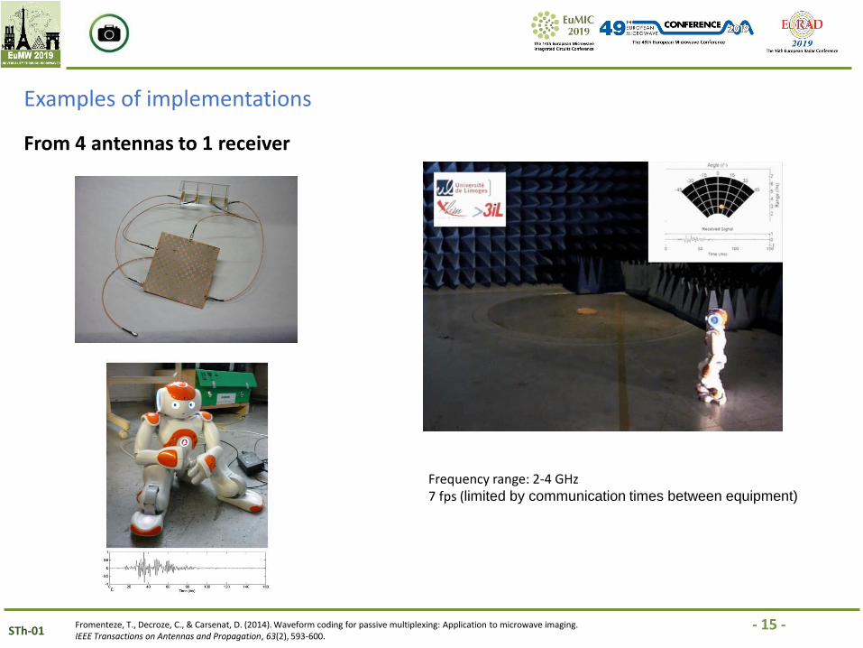
Examples of implementations
Fromenteze, T., Decroze, C., & Carsenat, D. (2014). Waveform coding for passive multiplexing: Application to microwave imaging. IEEE Transactions on Antennas and Propagation, 63(2), 593-600.
Frequency range: 2-4 GHz7 fps (limited by communication times between equipment)
From 4 antennas to 1 receiver
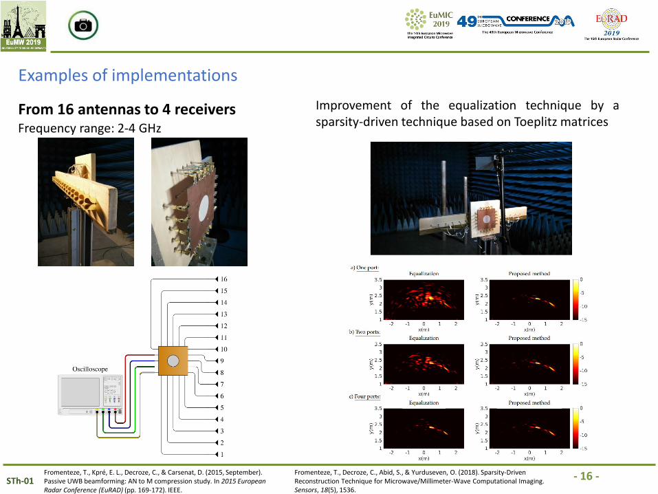
- 16 -STh-01Fromenteze, T., Kpré, E. L., Decroze, C., & Carsenat, D. (2015, September). Passive UWB beamforming: AN to M compression study. In 2015 European Radar Conference (EuRAD) (pp. 169-172). IEEE.
Frequency range: 2-4 GHz
From 16 antennas to 4 receivers
Examples of implementations
Fromenteze, T., Decroze, C., Abid, S., & Yurduseven, O. (2018). Sparsity-Driven Reconstruction Technique for Microwave/Millimeter-Wave Computational Imaging. Sensors, 18(5), 1536.
Improvement of the equalization technique by asparsity-driven technique based on Toeplitz matrices
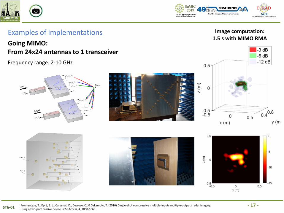
- 17 -STh-01Fromenteze, T., Kpré, E. L., Carsenat, D., Decroze, C., & Sakamoto, T. (2016). Single-shot compressive multiple-inputs multiple-outputs radar imaging using a two-port passive device. IEEE Access, 4, 1050-1060.
Frequency range: 2-10 GHz
Going MIMO:From 24x24 antennas to 1 transceiver
Examples of implementations Image computation: 1.5 s with MIMO RMA
- 18 -STh-01Fromenteze, T., Yurduseven, O., Berland, F., Decroze, C., Smith, D. R., & Yarovoy, A. G. (2019). A Transverse Spectrum Deconvolution Technique for MIMO Short-Range Fourier Imaging. IEEE Transactions on Geoscience and Remote Sensing.
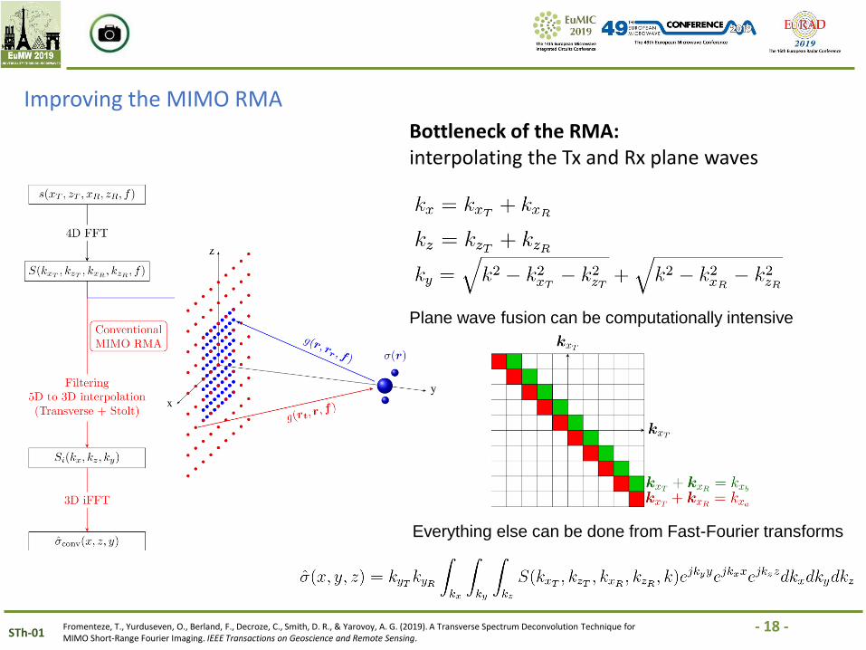
Improving the MIMO RMA
Bottleneck of the RMA: interpolating the Tx and Rx plane waves
Plane wave fusion can be computationally intensive
Everything else can be done from Fast-Fourier transforms
- 19 -STh-01Fromenteze, T., Yurduseven, O., Berland, F., Decroze, C., Smith, D. R., & Yarovoy, A. G. (2019). A Transverse Spectrum Deconvolution Technique for MIMO Short-Range Fourier Imaging. IEEE Transactions on Geoscience and Remote Sensing.
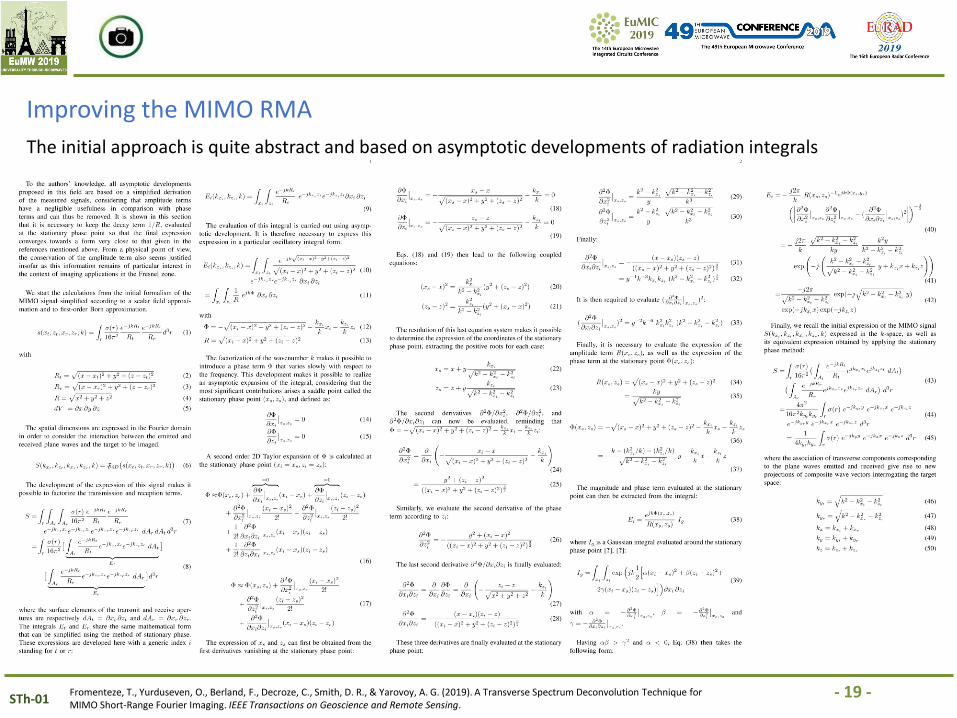
Improving the MIMO RMA
The initial approach is quite abstract and based on asymptotic developments of radiation integrals
- 20 -STh-01Fromenteze, T., Yurduseven, O., Berland, F., Decroze, C., Smith, D. R., & Yarovoy, A. G. (2019). A Transverse Spectrum Deconvolution Technique for MIMO Short-Range Fourier Imaging. IEEE Transactions on Geoscience and Remote Sensing.
Improving the MIMO RMA
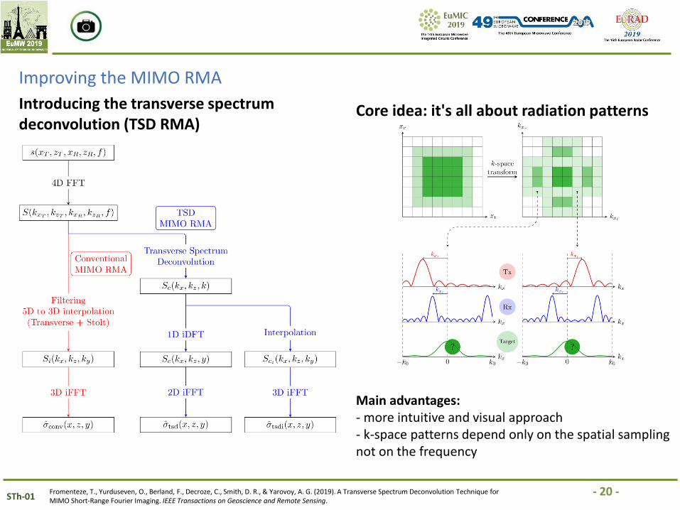
Introducing the transverse spectrum deconvolution (TSD RMA)
Core idea: it's all about radiation patterns
Main advantages:- more intuitive and visual approach- k-space patterns depend only on the spatial sampling not on the frequency
- 21 -STh-01Fromenteze, T., Yurduseven, O., Berland, F., Decroze, C., Smith, D. R., & Yarovoy, A. G. (2019). A Transverse Spectrum Deconvolution Technique for MIMO Short-Range Fourier Imaging. IEEE Transactions on Geoscience and Remote Sensing.
Improving the MIMO RMA
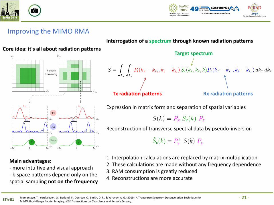
Core idea: it's all about radiation patterns
Main advantages:- more intuitive and visual approach- k-space patterns depend only on the spatial sampling not on the frequency
Interrogation of a spectrum through known radiation patterns
Tx radiation patterns Rx radiation patterns
Target spectrum
Expression in matrix form and separation of spatial variables
Reconstruction of transverse spectral data by pseudo-inversion
1. Interpolation calculations are replaced by matrix multiplication2. These calculations are made without any frequency dependence3. RAM consumption is greatly reduced4. Reconstructions are more accurate
- 22 -STh-01Fromenteze, T., Yurduseven, O., Berland, F., Decroze, C., Smith, D. R., & Yarovoy, A. G. (2019). A Transverse Spectrum Deconvolution Technique for MIMO Short-Range Fourier Imaging. IEEE Transactions on Geoscience and Remote Sensing.
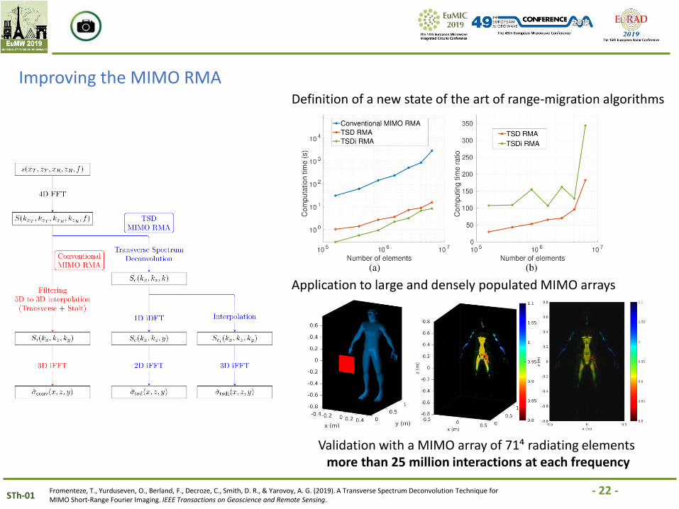
Improving the MIMO RMADefinition of a new state of the art of range-migration algorithms
Application to large and densely populated MIMO arrays
Validation with a MIMO array of 71⁴ radiating elementsmore than 25 million interactions at each frequency
- 23 -STh-01
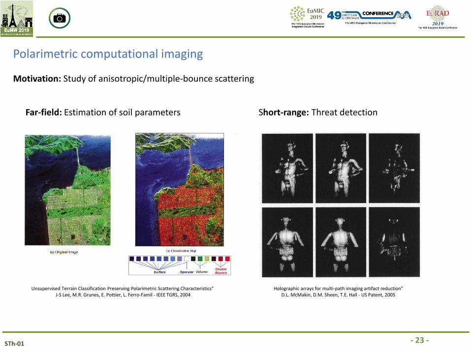
Polarimetric computational imaging
Motivation: Study of anisotropic/multiple-bounce scattering
Far-field: Estimation of soil parameters Short-range: Threat detection
Unsupervised Terrain Classification Preserving Polarimetric Scattering Characteristics"J-S Lee, M.R. Grunes, E. Pottier, L. Ferro-Famil - IEEE TGRS, 2004
Holographic arrays for multi-path imaging artifact reduction"D.L. McMakin, D.M. Sheen, T.E. Hall - US Patent, 2005
- 24 -STh-01
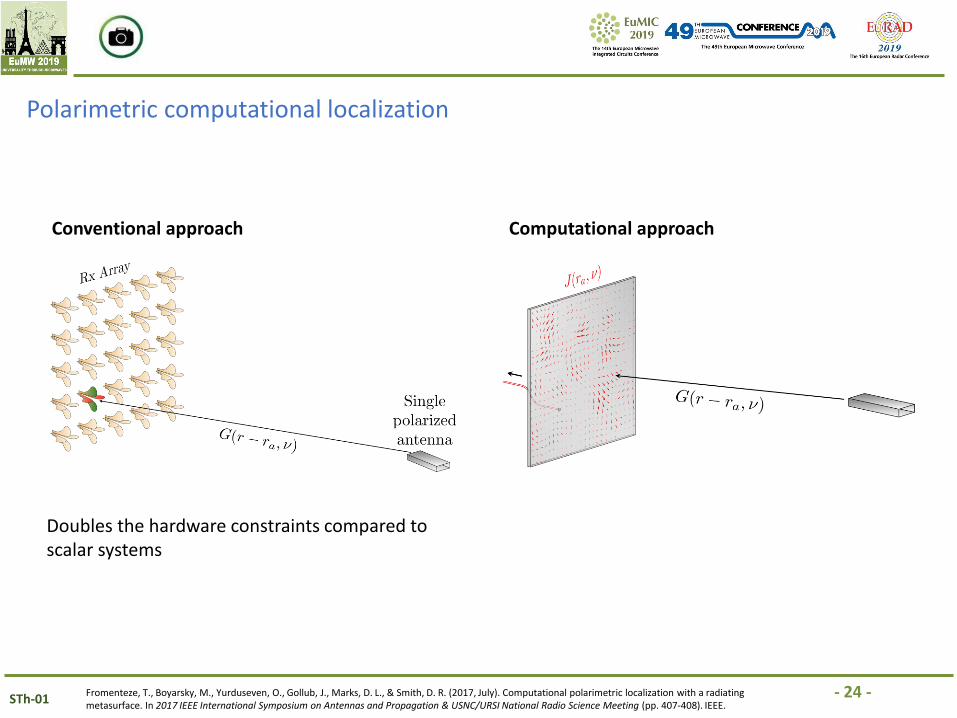
Polarimetric computational localization
Conventional approach Computational approach
Doubles the hardware constraints compared to scalar systems
Fromenteze, T., Boyarsky, M., Yurduseven, O., Gollub, J., Marks, D. L., & Smith, D. R. (2017, July). Computational polarimetric localization with a radiating metasurface. In 2017 IEEE International Symposium on Antennas and Propagation & USNC/URSI National Radio Science Meeting (pp. 407-408). IEEE.
- 25 -STh-01
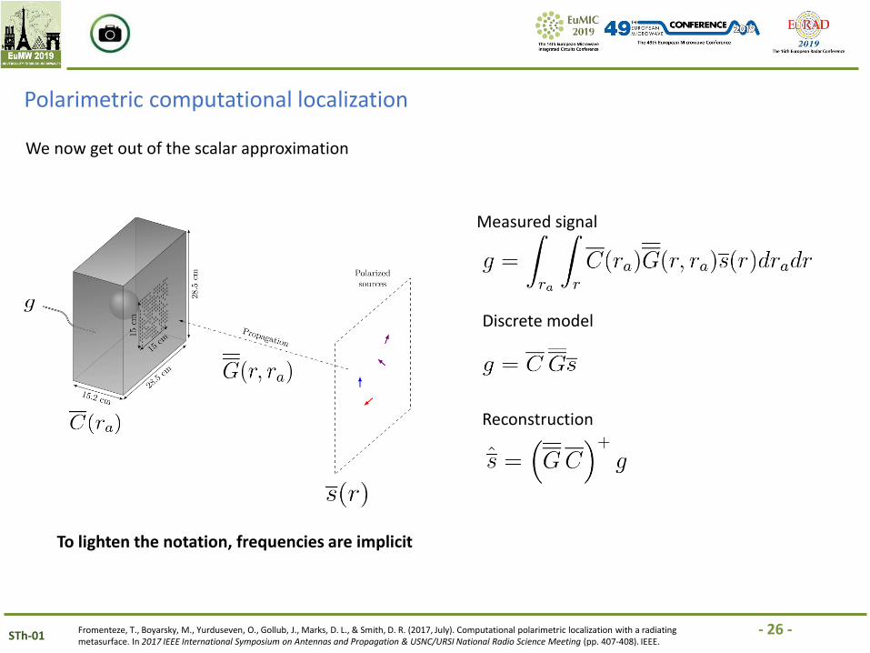
Polarimetric computational localization
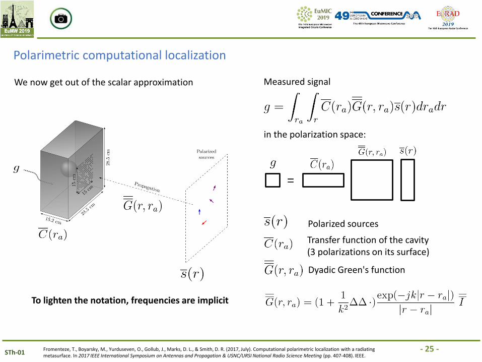
Measured signal
Fromenteze, T., Boyarsky, M., Yurduseven, O., Gollub, J., Marks, D. L., & Smith, D. R. (2017, July). Computational polarimetric localization with a radiating metasurface. In 2017 IEEE International Symposium on Antennas and Propagation & USNC/URSI National Radio Science Meeting (pp. 407-408). IEEE.
Polarized sources
Dyadic Green's function
Transfer function of the cavity(3 polarizations on its surface)
We now get out of the scalar approximation
To lighten the notation, frequencies are implicit
=
in the polarization space:
- 26 -STh-01
Polarimetric computational localization
Measured signal
Fromenteze, T., Boyarsky, M., Yurduseven, O., Gollub, J., Marks, D. L., & Smith, D. R. (2017, July). Computational polarimetric localization with a radiating metasurface. In 2017 IEEE International Symposium on Antennas and Propagation & USNC/URSI National Radio Science Meeting (pp. 407-408). IEEE.
We now get out of the scalar approximation
To lighten the notation, frequencies are implicit
Discrete model
Reconstruction
- 27 -STh-01
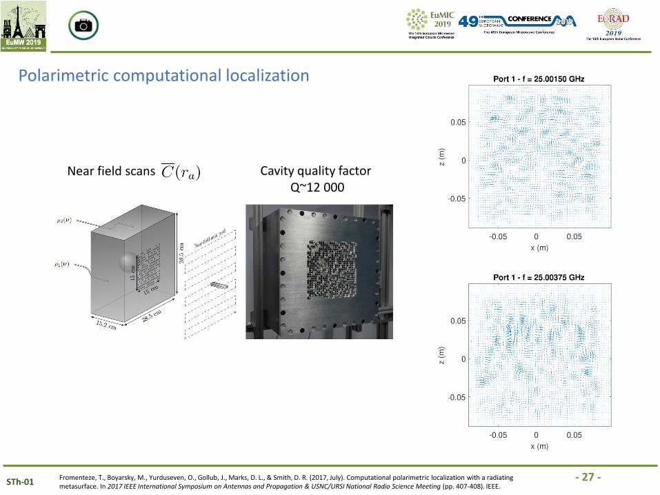
Polarimetric computational localization
Fromenteze, T., Boyarsky, M., Yurduseven, O., Gollub, J., Marks, D. L., & Smith, D. R. (2017, July). Computational polarimetric localization with a radiating metasurface. In 2017 IEEE International Symposium on Antennas and Propagation & USNC/URSI National Radio Science Meeting (pp. 407-408). IEEE.
Near field scans Cavity quality factorQ~12 000
- 28 -STh-01
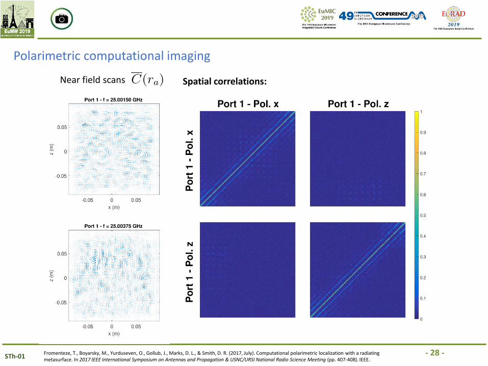
Polarimetric computational imaging
Fromenteze, T., Boyarsky, M., Yurduseven, O., Gollub, J., Marks, D. L., & Smith, D. R. (2017, July). Computational polarimetric localization with a radiating metasurface. In 2017 IEEE International Symposium on Antennas and Propagation & USNC/URSI National Radio Science Meeting (pp. 407-408). IEEE.
Near field scans Spatial correlations:
- 29 -STh-01
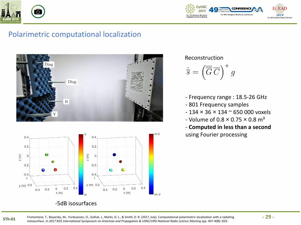
Polarimetric computational localization
Fromenteze, T., Boyarsky, M., Yurduseven, O., Gollub, J., Marks, D. L., & Smith, D. R. (2017, July). Computational polarimetric localization with a radiating metasurface. In 2017 IEEE International Symposium on Antennas and Propagation & USNC/URSI National Radio Science Meeting (pp. 407-408). IEEE.
-5dB isosurfaces
- Frequency range : 18.5-26 GHz- 801 Frequency samples- 134 × 36 × 134 ~ 650 000 voxels- Volume of 0.8 × 0.75 × 0.8 m³- Computed in less than a second using Fourier processing
Reconstruction
- 30 -STh-01
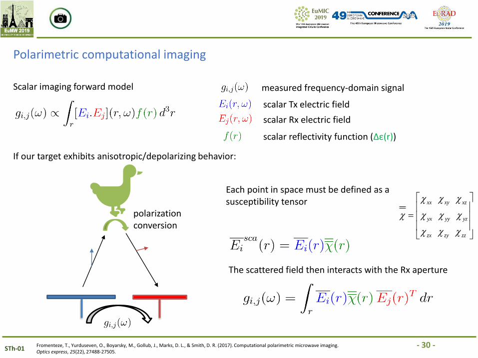
Polarimetric computational imaging
Scalar imaging forward model measured frequency-domain signal
scalar Tx electric field
scalar Rx electric field
scalar reflectivity function (Δε(r))
If our target exhibits anisotropic/depolarizing behavior:
polarization conversion
Each point in space must be defined as a susceptibility tensor
The scattered field then interacts with the Rx aperture
xx xy xz
yx yy yz
zx zy zz
=
Fromenteze, T., Yurduseven, O., Boyarsky, M., Gollub, J., Marks, D. L., & Smith, D. R. (2017). Computational polarimetric microwave imaging. Optics express, 25(22), 27488-27505.
- 31 -STh-01
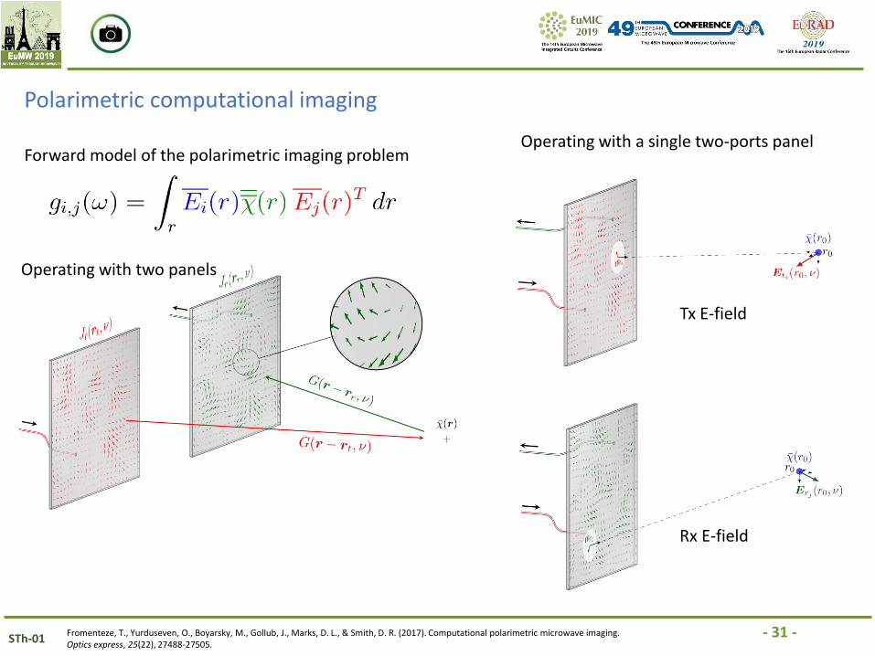
Polarimetric computational imaging
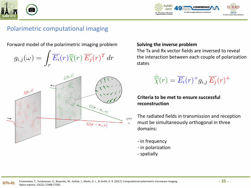
Forward model of the polarimetric imaging problem
Fromenteze, T., Yurduseven, O., Boyarsky, M., Gollub, J., Marks, D. L., & Smith, D. R. (2017). Computational polarimetric microwave imaging. Optics express, 25(22), 27488-27505.
Operating with two panels
Operating with a single two-ports panel
Tx E-field
Rx E-field
- 32 -STh-01
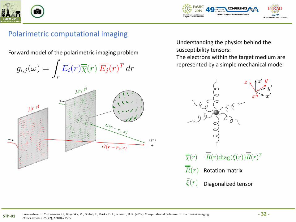
Polarimetric computational imaging
Forward model of the polarimetric imaging problem
Fromenteze, T., Yurduseven, O., Boyarsky, M., Gollub, J., Marks, D. L., & Smith, D. R. (2017). Computational polarimetric microwave imaging. Optics express, 25(22), 27488-27505.
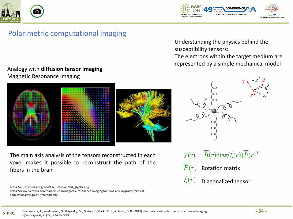
Understanding the physics behind the susceptibility tensors:The electrons within the target medium are represented by a simple mechanical model
Rotation matrix
Diagonalized tensor
- 33 -STh-01
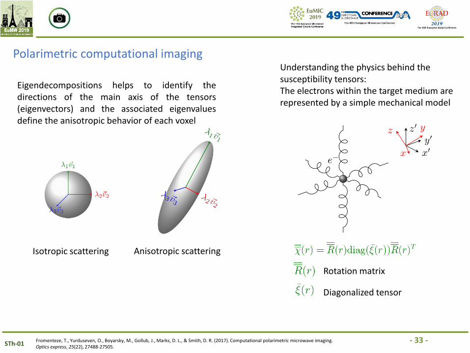
Polarimetric computational imaging
Fromenteze, T., Yurduseven, O., Boyarsky, M., Gollub, J., Marks, D. L., & Smith, D. R. (2017). Computational polarimetric microwave imaging. Optics express, 25(22), 27488-27505.
Eigendecompositions helps to identify thedirections of the main axis of the tensors(eigenvectors) and the associated eigenvaluesdefine the anisotropic behavior of each voxel
Isotropic scattering Anisotropic scattering
Understanding the physics behind the susceptibility tensors:The electrons within the target medium are represented by a simple mechanical model
Rotation matrix
Diagonalized tensor
- 34 -STh-01
Polarimetric computational imaging
Fromenteze, T., Yurduseven, O., Boyarsky, M., Gollub, J., Marks, D. L., & Smith, D. R. (2017). Computational polarimetric microwave imaging. Optics express, 25(22), 27488-27505.
Analogy with diffusion tensor imaging Magnetic Resonance Imaging
https://en.wikipedia.org/wiki/File:DiffusionMRI_glyphs.pnghttps://www.siemens-healthineers.com/magnetic-resonance-imaging/options-and-upgrades/clinical-applications/syngo-dti-tractography
The main axis analysis of the tensors reconstructed in eachvoxel makes it possible to reconstruct the path of thefibers in the brain
Understanding the physics behind the susceptibility tensors:The electrons within the target medium are represented by a simple mechanical model
Rotation matrix
Diagonalized tensor
- 35 -STh-01
Polarimetric computational imaging
Forward model of the polarimetric imaging problem Solving the inverse problemThe Tx and Rx vector fields are inversed to reveal the interaction between each couple of polarization states
Criteria to be met to ensure successful reconstruction
The radiated fields in transmission and reception must be simultaneously orthogonal in three domains:
- in frequency- in polarization- spatially
Fromenteze, T., Yurduseven, O., Boyarsky, M., Gollub, J., Marks, D. L., & Smith, D. R. (2017). Computational polarimetric microwave imaging. Optics express, 25(22), 27488-27505.
- 36 -STh-01
Polarimetric computational imaging
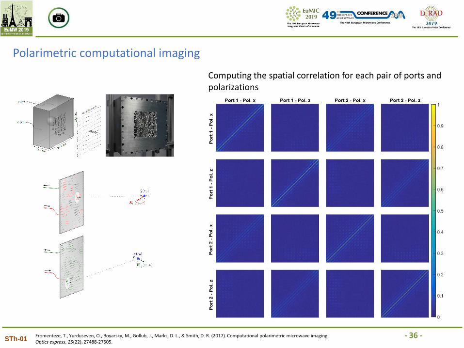
Computing the spatial correlation for each pair of ports and polarizations
Fromenteze, T., Yurduseven, O., Boyarsky, M., Gollub, J., Marks, D. L., & Smith, D. R. (2017). Computational polarimetric microwave imaging. Optics express, 25(22), 27488-27505.
- 37 -STh-01
Polarimetric computational imaging
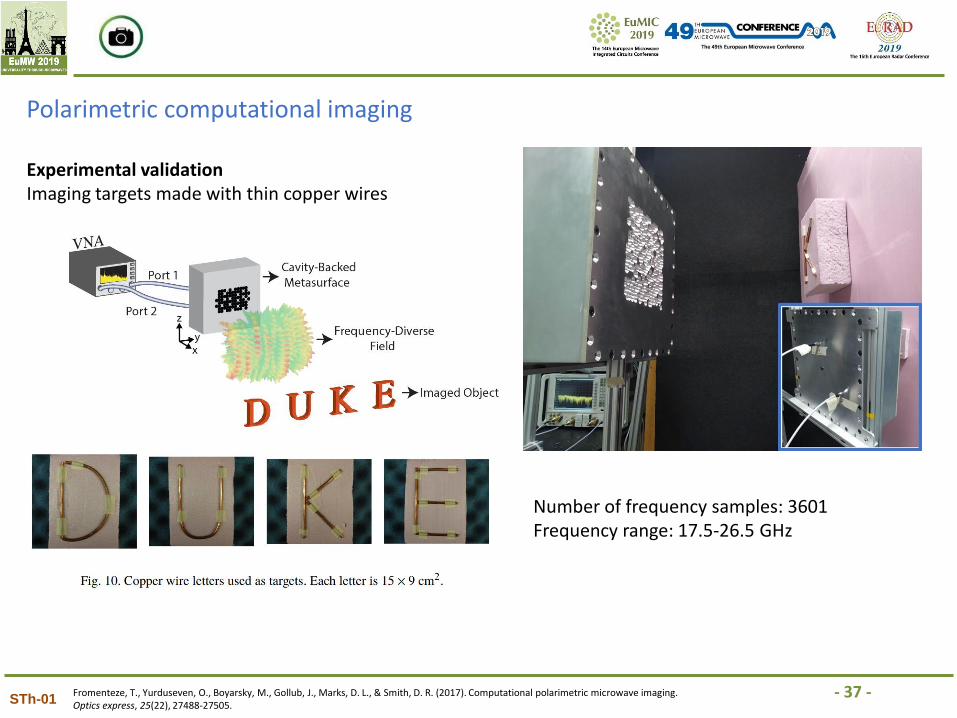
Experimental validationImaging targets made with thin copper wires
Fromenteze, T., Yurduseven, O., Boyarsky, M., Gollub, J., Marks, D. L., & Smith, D. R. (2017). Computational polarimetric microwave imaging. Optics express, 25(22), 27488-27505.
Number of frequency samples: 3601Frequency range: 17.5-26.5 GHz
- 38 -STh-01
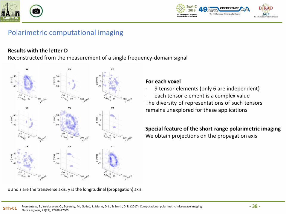
Polarimetric computational imaging
Results with the letter DReconstructed from the measurement of a single frequency-domain signal
For each voxel- 9 tensor elements (only 6 are independent)- each tensor element is a complex valueThe diversity of representations of such tensorsremains unexplored for these applications
x and z are the transverse axis, y is the longitudinal (propagation) axis
Special feature of the short-range polarimetric imagingWe obtain projections on the propagation axis
Fromenteze, T., Yurduseven, O., Boyarsky, M., Gollub, J., Marks, D. L., & Smith, D. R. (2017). Computational polarimetric microwave imaging. Optics express, 25(22), 27488-27505.
- 39 -STh-01
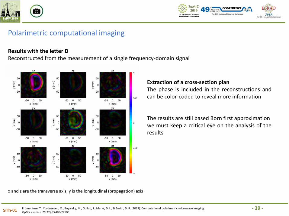
Polarimetric computational imaging
Results with the letter DReconstructed from the measurement of a single frequency-domain signal
x and z are the transverse axis, y is the longitudinal (propagation) axis
Extraction of a cross-section planThe phase is included in the reconstructions andcan be color-coded to reveal more information
The results are still based Born first approximationwe must keep a critical eye on the analysis of theresults
Fromenteze, T., Yurduseven, O., Boyarsky, M., Gollub, J., Marks, D. L., & Smith, D. R. (2017). Computational polarimetric microwave imaging. Optics express, 25(22), 27488-27505.
- 40 -STh-01
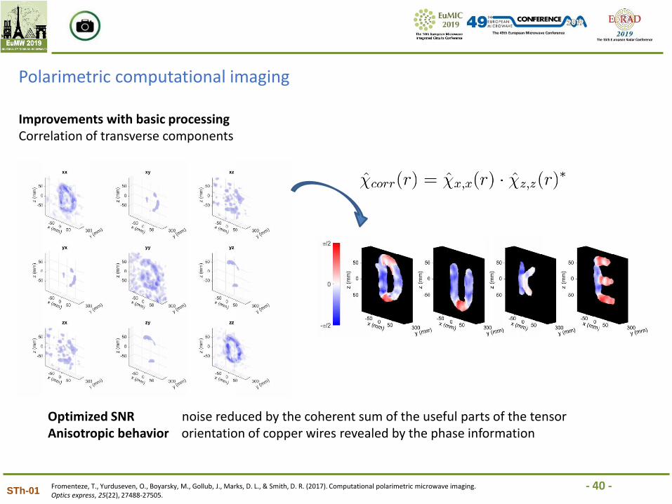
Polarimetric computational imaging
Improvements with basic processingCorrelation of transverse components
Optimized SNR noise reduced by the coherent sum of the useful parts of the tensorAnisotropic behavior orientation of copper wires revealed by the phase information
Fromenteze, T., Yurduseven, O., Boyarsky, M., Gollub, J., Marks, D. L., & Smith, D. R. (2017). Computational polarimetric microwave imaging. Optics express, 25(22), 27488-27505.
- 41 -STh-01
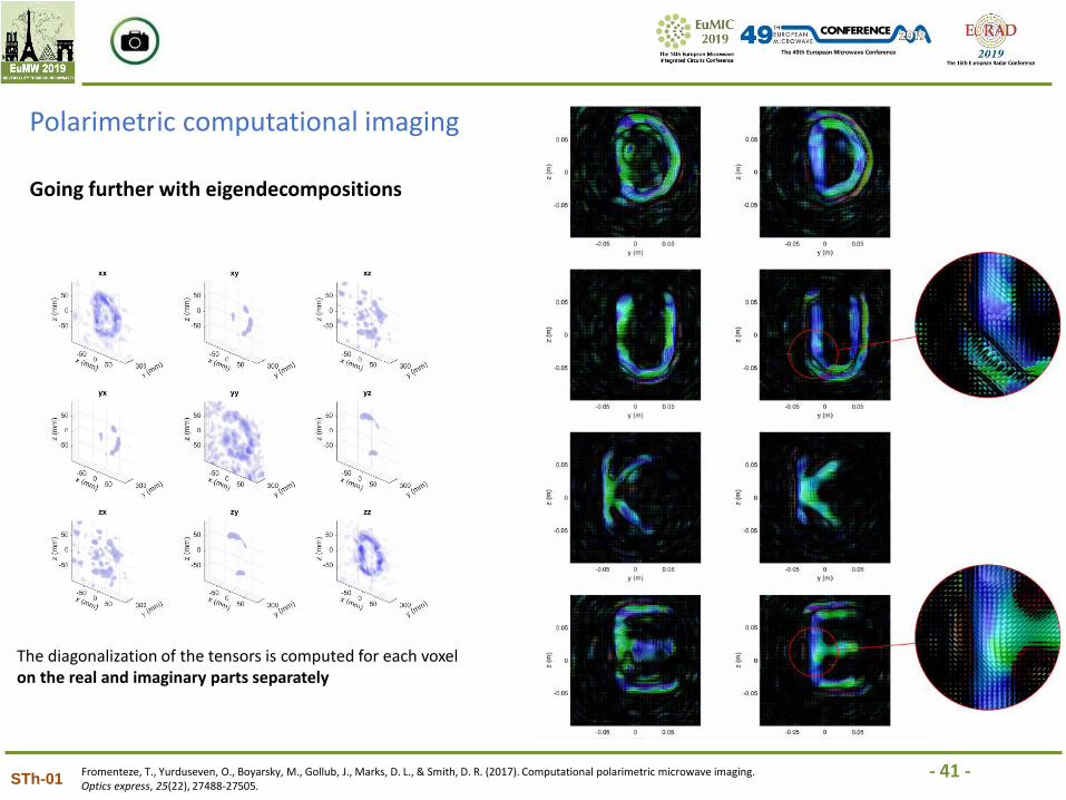
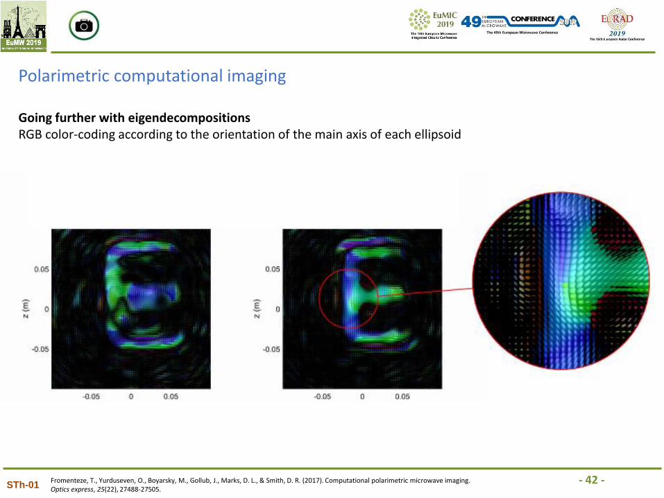
Polarimetric computational imaging
Going further with eigendecompositions
The diagonalization of the tensors is computed for each voxel on the real and imaginary parts separately
Fromenteze, T., Yurduseven, O., Boyarsky, M., Gollub, J., Marks, D. L., & Smith, D. R. (2017). Computational polarimetric microwave imaging. Optics express, 25(22), 27488-27505.
- 42 -STh-01
Polarimetric computational imaging
Going further with eigendecompositionsRGB color-coding according to the orientation of the main axis of each ellipsoid
Fromenteze, T., Yurduseven, O., Boyarsky, M., Gollub, J., Marks, D. L., & Smith, D. R. (2017). Computational polarimetric microwave imaging. Optics express, 25(22), 27488-27505.
- 43 -STh-01
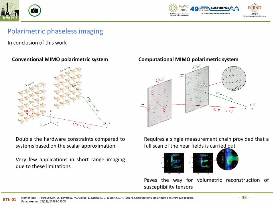
Polarimetric phaseless imaging
In conclusion of this work
Conventional MIMO polarimetric system Computational MIMO polarimetric system
Double the hardware constraints compared tosystems based on the scalar approximation
Very few applications in short range imagingdue to these limitations
Requires a single measurement chain provided that afull scan of the near fields is carried out
Paves the way for volumetric reconstruction ofsusceptibility tensors
Fromenteze, T., Yurduseven, O., Boyarsky, M., Gollub, J., Marks, D. L., & Smith, D. R. (2017). Computational polarimetric microwave imaging. Optics express, 25(22), 27488-27505.
- 44 -STh-01
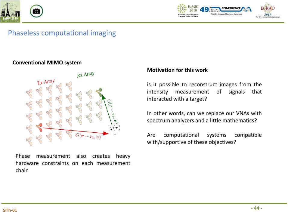
Phaseless computational imaging
Conventional MIMO system
Phase measurement also creates heavyhardware constraints on each measurementchain
Motivation for this work
is it possible to reconstruct images from theintensity measurement of signals thatinteracted with a target?
In other words, can we replace our VNAs withspectrum analyzers and a little mathematics?
Are computational systems compatiblewith/supportive of these objectives?
- 45 -STh-01
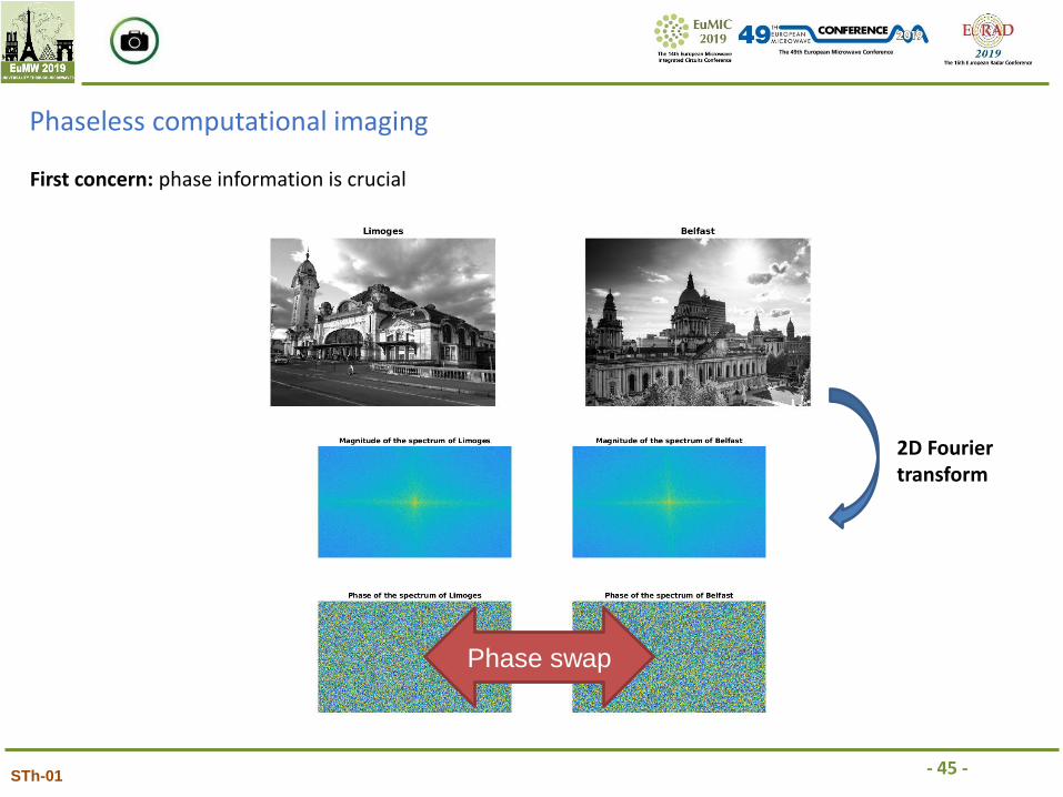
Phaseless computational imaging
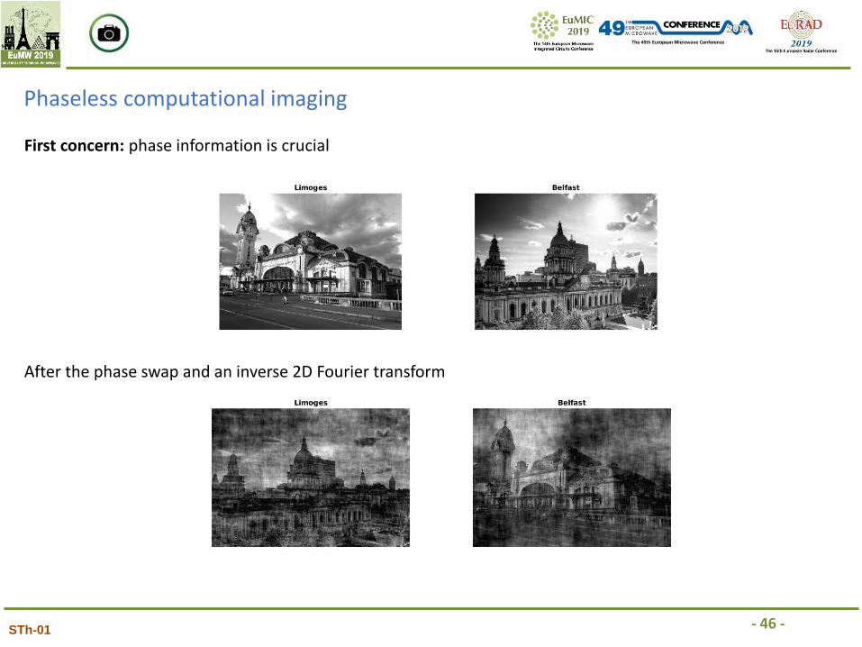
First concern: phase information is crucial
Phase swap
2D Fourier transform
- 46 -STh-01
Phaseless computational imaging
First concern: phase information is crucial
After the phase swap and an inverse 2D Fourier transform
- 47 -STh-01
Phaseless computational imaging
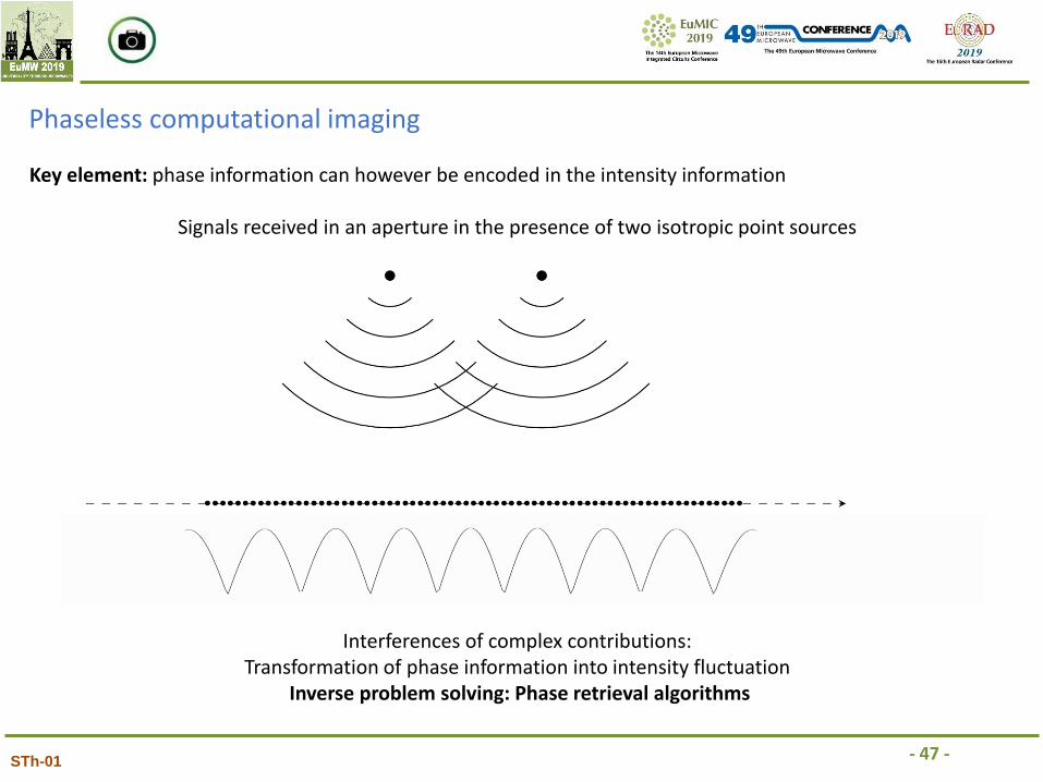
Key element: phase information can however be encoded in the intensity information
Signals received in an aperture in the presence of two isotropic point sources
Interferences of complex contributions:Transformation of phase information into intensity fluctuation
Inverse problem solving: Phase retrieval algorithms
- 48 -STh-01
Phaseless computational imaging
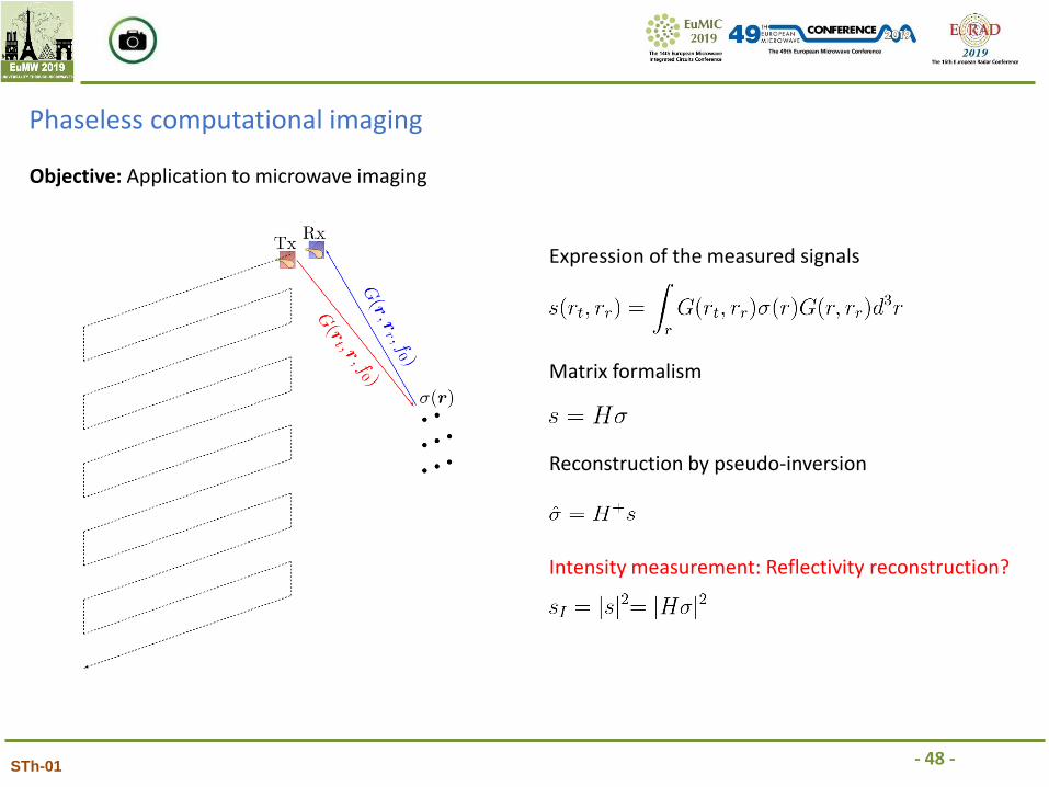
Objective: Application to microwave imaging
Expression of the measured signals
Matrix formalism
Reconstruction by pseudo-inversion
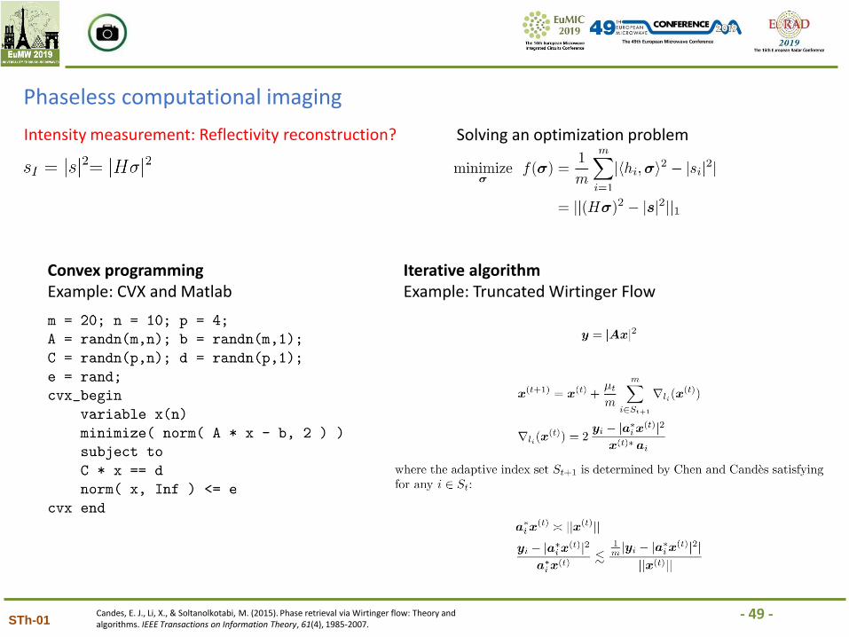
Intensity measurement: Reflectivity reconstruction?
- 49 -STh-01
Phaseless computational imaging
Intensity measurement: Reflectivity reconstruction? Solving an optimization problem
Convex programmingExample: CVX and Matlab
Iterative algorithmExample: Truncated Wirtinger Flow
Candes, E. J., Li, X., & Soltanolkotabi, M. (2015). Phase retrieval via Wirtinger flow: Theory and algorithms. IEEE Transactions on Information Theory, 61(4), 1985-2007.
- 50 -STh-01
Phaseless computational imaging
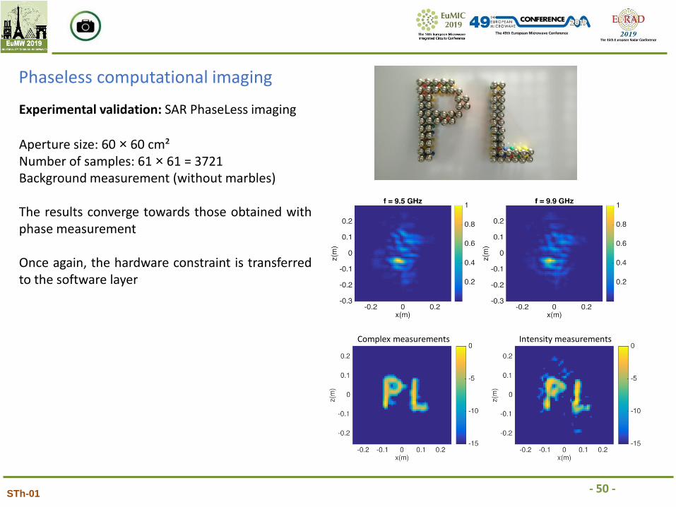
Experimental validation: SAR PhaseLess imaging
Complex measurements Intensity measurements
Aperture size: 60 × 60 cm²Number of samples: 61 × 61 = 3721Background measurement (without marbles)
The results converge towards those obtained withphase measurement
Once again, the hardware constraint is transferredto the software layer
- 51 -STh-01
Phaseless computational imaging
Fromenteze, T., Liu, X., Boyarsky, M., Gollub, J., & Smith, D. R. (2016). Phaseless computational imaging with a radiating metasurface. Optics express, 24(15), 16760-16776.
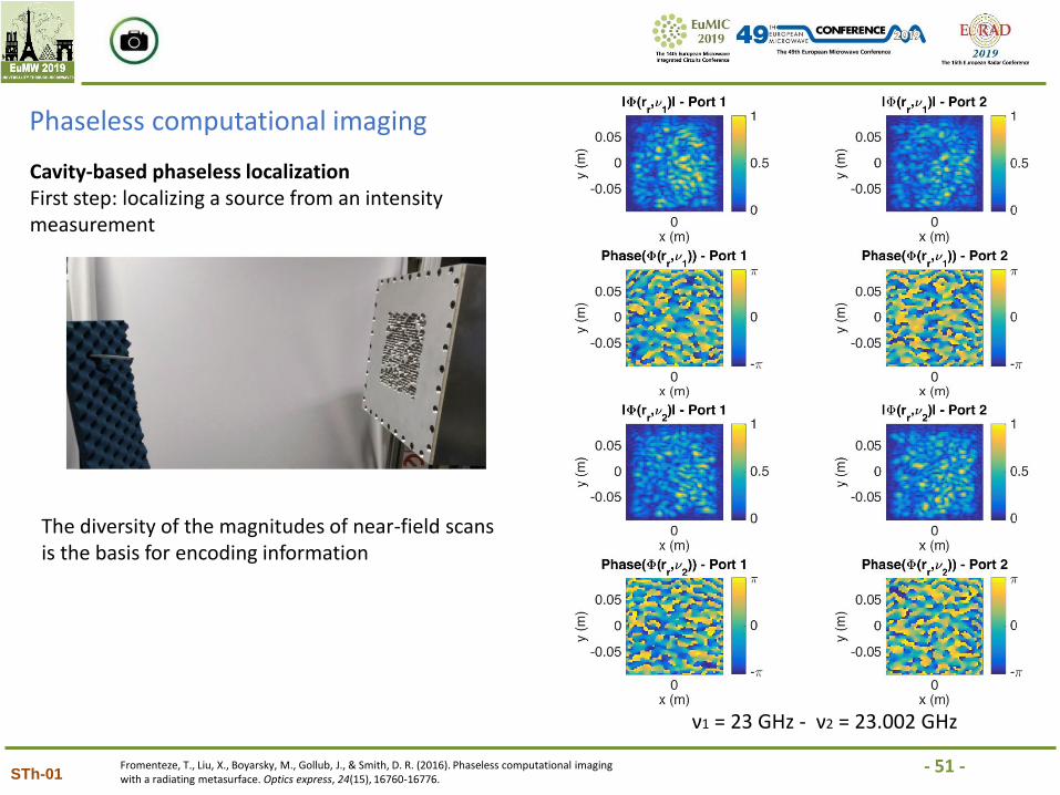
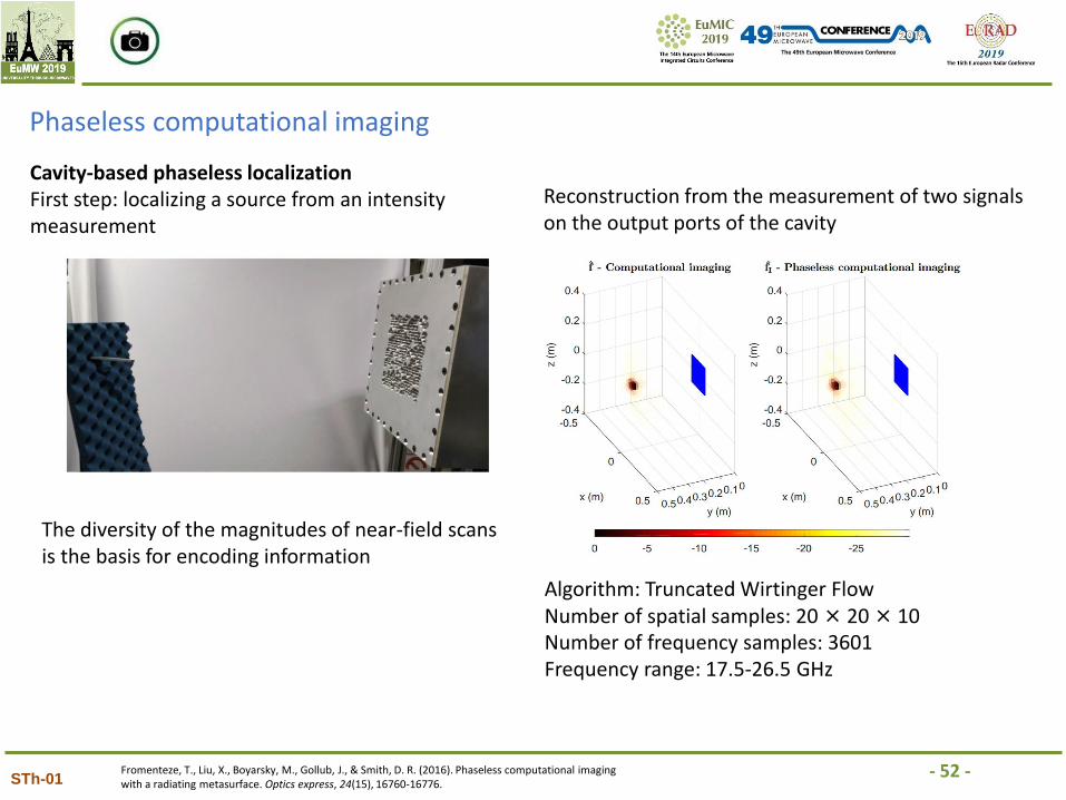
Cavity-based phaseless localizationFirst step: localizing a source from an intensity measurement
ν1 = 23 GHz - ν2 = 23.002 GHz
The diversity of the magnitudes of near-field scans is the basis for encoding information
- 52 -STh-01
Phaseless computational imaging
Fromenteze, T., Liu, X., Boyarsky, M., Gollub, J., & Smith, D. R. (2016). Phaseless computational imaging with a radiating metasurface. Optics express, 24(15), 16760-16776.
Cavity-based phaseless localizationFirst step: localizing a source from an intensity measurement
The diversity of the magnitudes of near-field scans is the basis for encoding information
Reconstruction from the measurement of two signals on the output ports of the cavity
Algorithm: Truncated Wirtinger FlowNumber of spatial samples: 20 × 20 × 10Number of frequency samples: 3601Frequency range: 17.5-26.5 GHz
- 53 -STh-01
Phaseless computational imaging
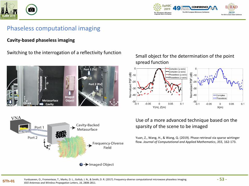
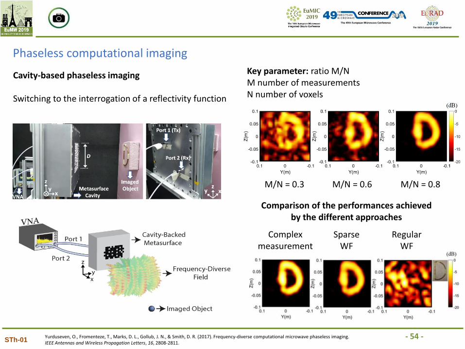
Cavity-based phaseless imaging
Switching to the interrogation of a reflectivity function
Yurduseven, O., Fromenteze, T., Marks, D. L., Gollub, J. N., & Smith, D. R. (2017). Frequency-diverse computational microwave phaseless imaging. IEEE Antennas and Wireless Propagation Letters, 16, 2808-2811.
Small object for the determination of the point spread function
Use of a more advanced technique based on the sparsity of the scene to be imaged
Yuan, Z., Wang, H., & Wang, Q. (2019). Phase retrieval via sparse wirtingerflow. Journal of Computational and Applied Mathematics, 355, 162-173.
- 54 -STh-01
Phaseless computational imaging
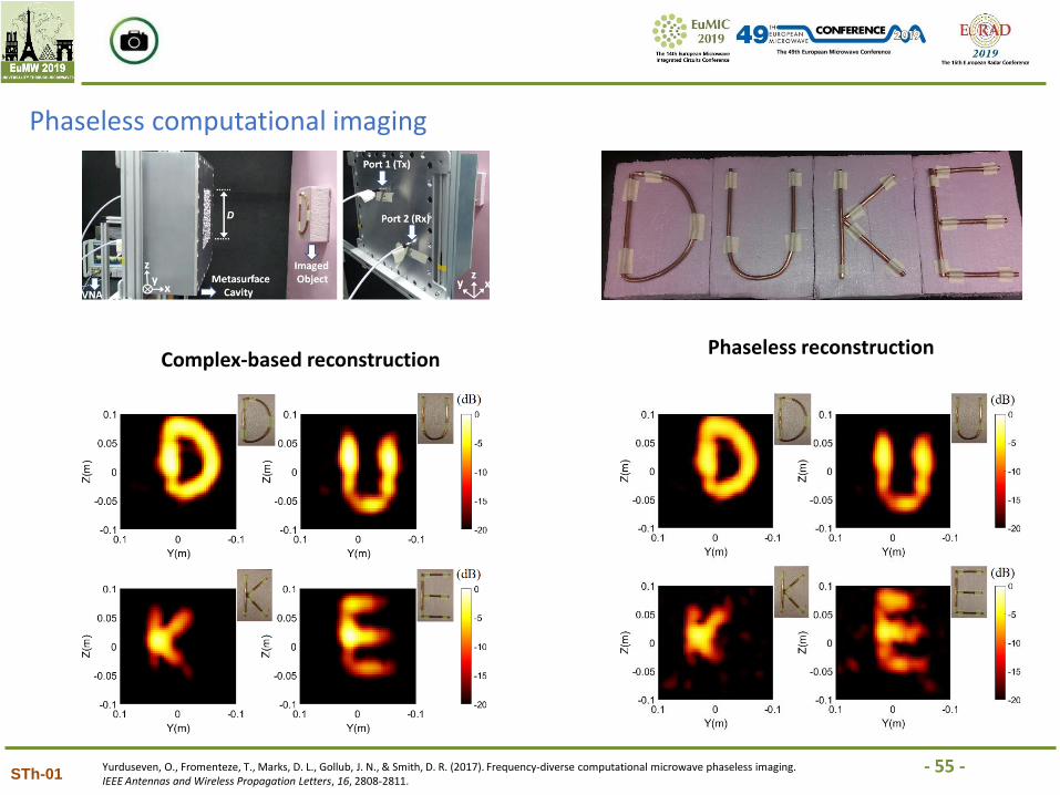
Cavity-based phaseless imaging
Switching to the interrogation of a reflectivity function
Yurduseven, O., Fromenteze, T., Marks, D. L., Gollub, J. N., & Smith, D. R. (2017). Frequency-diverse computational microwave phaseless imaging. IEEE Antennas and Wireless Propagation Letters, 16, 2808-2811.
Key parameter: ratio M/NM number of measurements N number of voxels
M/N = 0.3 M/N = 0.8
Complex measurement
SparseWF
RegularWF
M/N = 0.6
Comparison of the performances achieved by the different approaches
- 55 -STh-01
Phaseless computational imaging
Complex-based reconstructionPhaseless reconstruction
Yurduseven, O., Fromenteze, T., Marks, D. L., Gollub, J. N., & Smith, D. R. (2017). Frequency-diverse computational microwave phaseless imaging. IEEE Antennas and Wireless Propagation Letters, 16, 2808-2811.
- 56 -
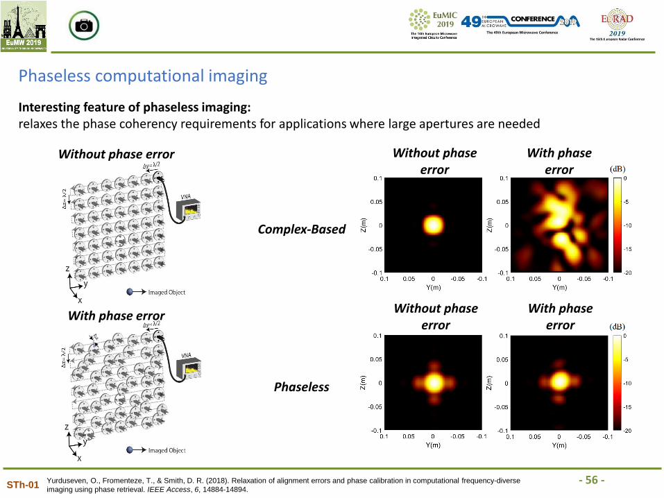
Interesting feature of phaseless imaging:relaxes the phase coherency requirements for applications where large apertures are needed
STh-01
Phaseless computational imaging
Complex-Based
Phaseless
Yurduseven, O., Fromenteze, T., & Smith, D. R. (2018). Relaxation of alignment errors and phase calibration in computational frequency-diverse
imaging using phase retrieval. IEEE Access, 6, 14884-14894.
Without phase error
With phase error
Without phase error
With phase error
Without phase error
With phase error
MODERN ADVANCES IN COMPUTATIONAL IMAGING AT MICROWAVE AND MILLIMETRE-WAVE FREQUENCIES
Okan Yurduseven#1, Thomas Fromentèze#2
#1Queen’s University Belfast, UK
#2Xlim Research Institute, University of Limoges, France
[email protected], [email protected]
STh-01