Embed Size (px)
Citation preview

MTR INC
MODERN TECHNOLOGY RESOURCES, INC.
GEOTECHNICAL REPORTPLANNED DEVELOPMENT
Project No. 2015-31APN 544-39-079
0 Helen Way, Los GatosSanta Clara County, CA
Prepared by: Modern Technology Resources, Inc.December 2nd, 2015
Igor Kleyner, Ph.D., C.E., G.E.Registered Geotechnical Engineer No. 2873
1485 BAYSHORE BOULEVARD , SAN FRANCISCO, CA 94124TEL (415) 859-9532 EMAIL [email protected]
CIVIL ENGINEERING LICENSE: C 68621GEOTECHNICAL ENGINEERING LICENSE: G2 2873

Project No. 2015-31 Page 1
1.0 INTRODUCTION ....................................................................... 3
2.0 PROPOSED CONSTRUCTION ..................................................... 3
3.0 SCOPE OF WORK ..................................................................... 3
4.0 SITE INVESTIGATION ................................................................ 4
4.1 SITE DETAILS ............................................................................................. 4 4.1.1 Topography. ................................................................................................................. 4
4.2 SUBSURFACE CONDITIONS ...................................................................... 5 4.2.1 Geology. ....................................................................................................................... 5 4.2.2 Subsurface Investigation and Laboratory Testing. ......................................................... 5
4.3 GEOLOGIC HAZARDS ................................................................................ 6 4.3.1 Active Land Sliding. ...................................................................................................... 6 4.3.2 Earthquake-Induced Land sliding. ................................................................................ 6 4.3.3 Excavation Stability. ...................................................................................................... 6 4.3.4 Water Seepage and Existing Drainage Pipes. ................................................................ 7 4.3.5 Seismic Hazards and Seismic Ground Shaking. ............................................................. 7 4.3.6 Fault-Rupture................................................................................................................ 7 4.3.7 Liquefaction. ................................................................................................................. 7 4.3.8 Soil Erosion Control. ..................................................................................................... 8
4.4 SEISMICITY ............................................................................................... 8 4.4.1 Regional Tectonics. ....................................................................................................... 8 4.4.2 Fault Distances. ............................................................................................................ 8 4.4.3 Earthquake Probabilities............................................................................................... 9 4.4.4 U.S. Geological Survey Seismic Design Parameters. .................................................... 10
5.0 CONCLUSIONS AND RECOMMENDATIONS .............................. 10
6.0 GEOTECHNICAL DESIGN CRITERIA........................................... 11
6.1 EARTHWORK OPERATIONS ..................................................................... 11 6.1.1 Demolition and Clearing............................................................................................. 11 6.1.2 Excavation. ................................................................................................................. 11 6.1.3 Over-Excavation. ......................................................................................................... 11 6.1.4 Engineering Fill. ......................................................................................................... 11 6.1.5 Shoring and Underpinning. ........................................................................................ 12
Project No. 2015-31 Page 2
6.1.6 Temporary Slopes. ...................................................................................................... 13 6.1.7 Finished Slopes. ......................................................................................................... 13 6.1.8 Drainage and Erosion Control. .................................................................................... 14
6.2 FOUNDATIONS ....................................................................................... 14 6.2.1 Spread Footings. ......................................................................................................... 14 6.2.2 Mat Foundation. ........................................................................................................ 15
6.3 DRILLED PIER ......................................................................................... 15
6.4 SLAB-ON-GRADE ..................................................................................... 16
6.5 RETAINING WALLS ................................................................................. 16
7.0 FOLLOW-UP GEOTECHNICAL SERVICES ................................... 18
8.0 LIMITATIONS ......................................................................... 18
9.0 REFERENCES .......................................................................... 19
10.0 APPENDICES .......................................................................... 21

Project No. 2015-31 Page 3
1.0 INTRODUCTION Modern Technology Resources, Inc. was retained to serve as a geotechnical engineer of record at the subject site located on Helen Way in Santa Clara County, California, Project No. 2015-31. In this report, we present the results of our foundation investigation for proposed construction to occur at the site. The project site is located in the Redwood Estates community, near the intersection at Mary Alice Way (Appendix A-1). The purpose of this investigation was to provide recommendations concerning the soil and foundation engineering of the proposed residential building development. This investigation will be conducted using available plans and data, including: published maps (Appendix A), exploratory borehole and/or excavation data (Appendix B), keys to bedrock and soil descriptions (Appendix C), and USGS seismic design parameters (Appendix D). Also, as part of our service, we will review structural engineering plans for conformance and geotechnical recommendations.
The recommendations presented in this report are contingent on conducting an adequate monitoring and testing program during construction of the proposed development. Unless the Modern Technology Resources, Inc. is hired to perform the necessary tests, on-site reviews and observations during construction stage of the project or they are coordinated with our firm, Modern Technology Resources, Inc. will not be held responsible for compliance with design recommendations presented in this report.
2.0 PROPOSED CONSTRUCTION To our knowledge, the project sites consist of two adjacent, undeveloped lots. The proposed improvements at Helen Way will consist of residential conventional frame building.
3.0 SCOPE OF WORK The scope of our work included:
A site reconnaissance by the undersigned,
Subsurface exploration,
Engineering analyses of the available data,
The preparation of this report, which includes soil recommendations for the proposed building.

Project No. 2015-31 Page 4
The scope of our services did not include evaluation of the neighboring building, shoring and underpinning design and implementation. However, Modern Technology Resources, Inc. is available to consult regarding above matters if required. Also, the scope of our services did not include an environmental assessment or investigation for the presence of hazardous or toxic materials in the soil, groundwater or air, on, below or around the site.
4.0 SITE INVESTIGATION An initial site reconnaissance and subsurface exploration was performed by Igor Kleyner (GE2873, CE68621). Field investigations included borehole and trench excavation and observations for evidence of liquefaction and land sliding hazard potential at the project site. Land sliding potential was observed. Subsequent laboratory analyses yielded soil parameters as well as natural water content. Lab results correlate well with data from previous geological studies. Based on available and collected information, Modern Technology Resources, Inc. was able to make geotechnical engineering recommendations that adhere to current building codes and criteria.
4.1 SITE DETAILS
The project site consists of two adjacent, undeveloped lots (APN 544-039-079/APN 544-039-035) located in the Redwood Estates, a rural, unincorporated community in the Santa Cruz Mountains. It is accessed by State Route 17 approximately eight miles southwest from downtown Los Gatos. Terrain in the area is primarily steep and forested. The coordinates used to locate and map the site are: 37.154°N, 122.987°W.
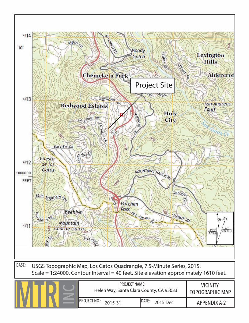
4.1.1 Topography. According to the USGS Topographic Map of the Los Gatos 7.5’ Quadrangle (Vicinity Topographic Map, Appendix A-2), the site is located on a hillside within the Santa Cruz Mountains with steep topography. Within the project site lots, elevations range from approximately 1,582 feet to 1,641 feet.

Project No. 2015-31 Page 5
4.2 SUBSURFACE CONDITIONS
4.2.1 Geology. The project site is in the La Honda subsidiary of the Santa Cruz structural block. Regionally, the area is characterized by the steep Santa Cruz Mountains that slope northeastward into the low-lying Santa Clara Valley. Motion along the San Andreas Fault is responsible for much of the topography and geologic features in the area.
According to the Geologic Map of the Los Gatos 7.5’ Quadrangle (Vicinity Geologic Map, Appendix A-3), the site and adjacent areas are situated on actively landsliding colluvial material (Ql) underlain by bedrock. Landslide motion is to the northeast towards the direction of Los Gatos Creek. Thickness and rate of movement of the colluvial material is unknown. Based on our field reconnaissance we estimate that the colluvium is relatively thin. The maximum depth we encountered colluvial material was approximately 1.5-2 feet before encountering bedrock. Underlying bedrock is mudstone of the Rice Member of the San Lorenzo Formation. Mudstone is a dense, nodular gray unit believed to have been deposited in middle bathyal depths due to the presence of benthic foraminifers. See USGS Cross Section in Appendix A-3b for approximate thicknesses of each unit.
4.2.2 Subsurface Investigation and Laboratory Testing. Personnel from this office visited the project site on Helen Way on December 17, 2015 to explore subsurface conditions. During excavation, we encountered colluvium containing severely weathered siltstone and mudstone inclusions with very low plasticity at the surface. Underlying the colluvium was Rices Member mudstone bedrock of the San Lorenzo Formation. Bedrock was yellowish-brown, brown, gray, and severely to moderately weathered. Weathering of the bedrock decreased with depth. Within our excavated trench, we found weathered bedrock near the surface. Free groundwater was not detected. Increasing depth produced less weathered bedrock. Borehole location and log of boring are found in Appendix B.
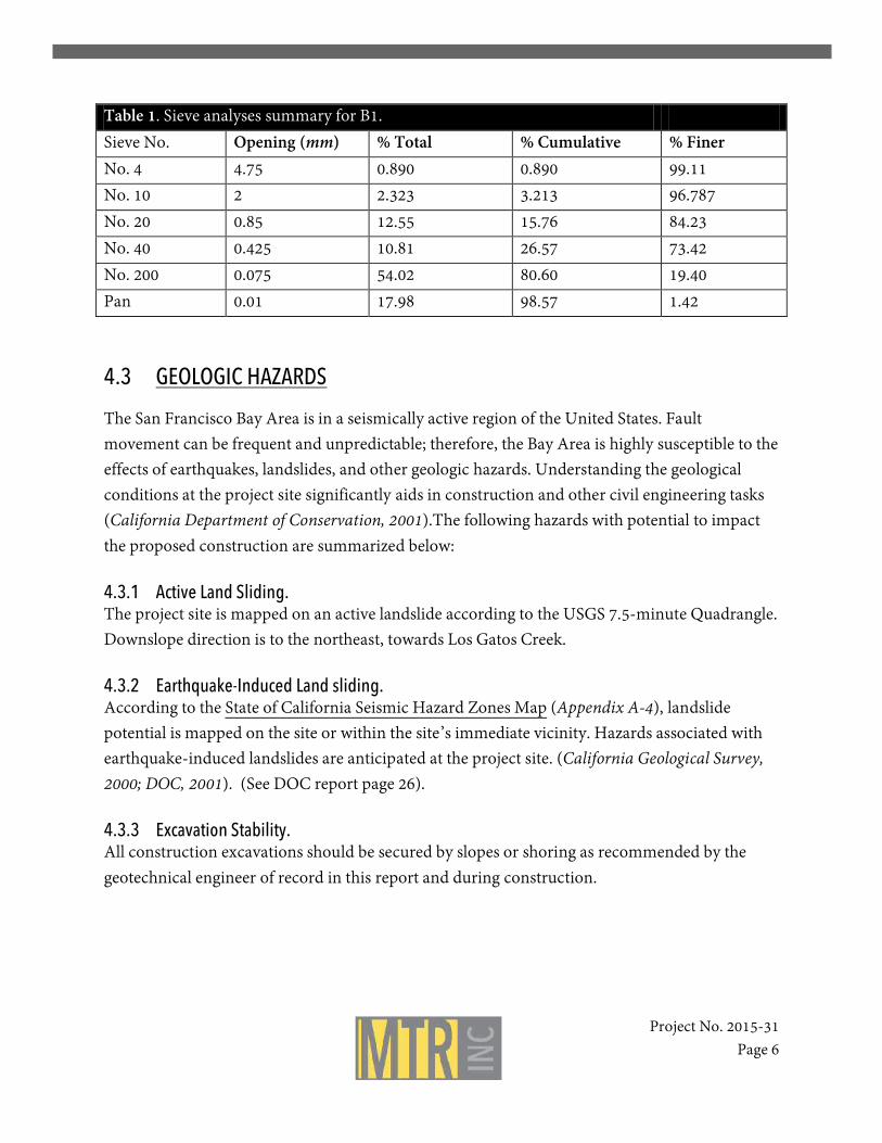
Samples were obtained from our excavations and subsequently analyzed at our off-site laboratory. 65.5% of material was retained in No. 40 and No. 200 sieves indicating mostly fine to very fine material. Average natural water content of the sample is approximately 10.49%.
Project No. 2015-31 Page 6
Table 1. Sieve analyses summary for B1. Sieve No. Opening (mm) % Total % Cumulative % Finer No. 4 4.75 0.890 0.890 99.11 No. 10 2 2.323 3.213 96.787 No. 20 0.85 12.55 15.76 84.23 No. 40 0.425 10.81 26.57 73.42 No. 200 0.075 54.02 80.60 19.40 Pan 0.01 17.98 98.57 1.42
4.3 GEOLOGIC HAZARDS
The San Francisco Bay Area is in a seismically active region of the United States. Fault movement can be frequent and unpredictable; therefore, the Bay Area is highly susceptible to the effects of earthquakes, landslides, and other geologic hazards. Understanding the geological conditions at the project site significantly aids in construction and other civil engineering tasks (California Department of Conservation, 2001).The following hazards with potential to impact the proposed construction are summarized below:
4.3.1 Active Land Sliding. The project site is mapped on an active landslide according to the USGS 7.5-minute Quadrangle. Downslope direction is to the northeast, towards Los Gatos Creek.
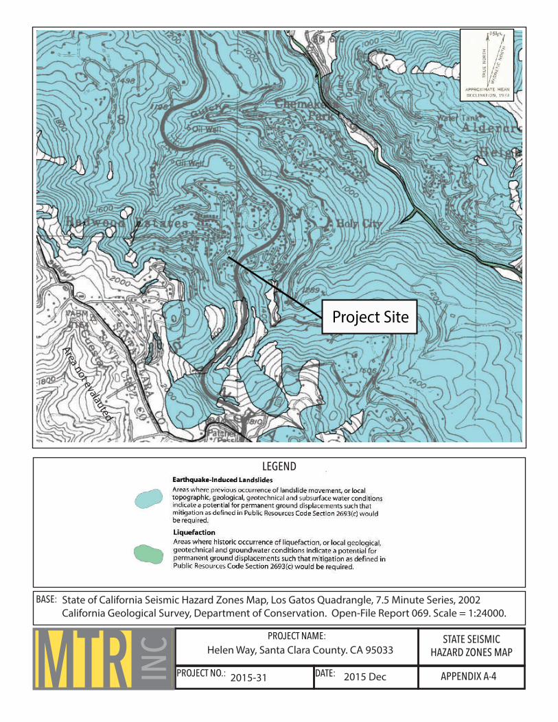
4.3.2 Earthquake-Induced Land sliding. According to the State of California Seismic Hazard Zones Map (Appendix A-4), landslide potential is mapped on the site or within the site’s immediate vicinity. Hazards associated with earthquake-induced landslides are anticipated at the project site. (California Geological Survey, 2000; DOC, 2001). (See DOC report page 26).
4.3.3 Excavation Stability. All construction excavations should be secured by slopes or shoring as recommended by the geotechnical engineer of record in this report and during construction.

Project No. 2015-31 Page 7
4.3.4 Water Seepage and Existing Drainage Pipes. Seepage may be encountered in temporary excavations and existing drainage pipes during construction. Install new drainage systems as it is recommended by the geotechnical engineer of record in this report and during construction.
4.3.5 Seismic Hazards and Seismic Ground Shaking. Intensities of an earthquake are strongly dependent on the distance from the ruptured fault and geological character of the ground (Gibbs, 1974) (Wood, 1933). Earthquake effects must be considered due to the site’s proximity to regional earthquake sources. Hazard can be reduced by structural engineering design using soil and site seismic parameters, recommended by geotechnical engineer of record in this geotechnical report.
4.3.6 Fault-Rupture. No known active faults directly intersect the project sites on Helen Way. However the project site is located approximately 0.5 miles (2640 feet) west to southwest from the nearest fault trace of the active San Andreas Fault.
The potential for fault surface-rupture at the project site is low; however, it is still recommended that potential seismic hazards from active faults be factored into the proposed construction of the project. The likelihood that the San Francisco Bay Area will undergo at least one strong earthquake in the near future is high. For the purposes of reducing damage and minimizing loss of life, structures should be designed in accordance with seismic information from the latest editions and revisions of the California Building Code.
4.3.7 Liquefaction. The State of California Seismic Hazard Zones Map (Appendix A-4) indicates that the project site is not located within an area of liquefaction potential. Liquefaction typically occurs along shorelines in extremely unconsolidated material such as artificial fill. The project site is not in an area where the historic occurrence of liquefaction, or local geological, geotechnical, and groundwater conditions indicate a potential for permanent ground displacements. Mitigation measures defined in Public Resources Code Section 2693(c) would not be required (California Geological Survey, 2000; DOC, 2001).
Project No. 2015-31 Page 8
4.3.8 Soil Erosion Control. Exposed soil is subject to varying degrees of erosion from surface water, and in some degree, from wind scour. Erosion control measures should be implemented at the time of construction and after construction completion.
4.4 SEISMICITY
4.4.1 Regional Tectonics. The San Francisco Bay Area is seismically active due to the region’s proximity to a major plate boundary. The Pacific Plate, located west of the project site, moves northwest relative to the North American Plate to the east, at a rate of about two inches per year. Movement between the plates is accommodated by right-lateral slip on fault systems, most notably along the San Andreas Fault Zone which has slipped approximately 200 miles over 23 million years. The San Andreas Fault is a complex system of parallel and interconnecting faults, and fault activity varies along sections of the fault. Related active faults of interest in the Bay Area include the major San Gregorio, Hayward, and Calaveras Fault Zones, and other fault splinters of lesser activity such as the Rodgers Creek Fault, Concord-Green Valley Fault, and the Greenville Fault (Stoffer, 2006).
Faults are all roughly parallel to one another, and exhibit primarily right-lateral motion along with a small vertical component. Fault motion is responsible for many large magnitude earthquakes, such as the 7.9 Great San Francisco Earthquake in 1906 and the 6.9 Loma Prieta Earthquake in 1989. Understanding these fault systems and their relationship to the San Francisco Bay region is key to the longevity of the area’s growing population and urban developments (Stoffer, 2006).
4.4.2 Fault Distances. According to the California Geological Survey, an active fault is defined as causing surface displacement within Holocene time (the last ~11,000 years) (Jennings, 2010). The locations of the five nearest active faults are described below.

Project No. 2015-31 Page 9
Table 3. Fault distances from project site.
Fault Approximate distance from project site
San Andreas 0.7 miles northeast
Sargent 2.5 miles southeast
Monte Vista 6.2 miles northeast
San Gregorio 17 miles west
Calaveras 19 miles east
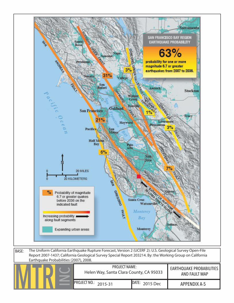
4.4.3 Earthquake Probabilities. In a collaborative study, the U.S. Geological Survey, California Geological Survey, and the Southern California Earthquake Center analyzed the probabilities of earthquake occurrence in the Bay Area. Geologists and seismologists concluded that there is a 63% chance that a 6.7 magnitude or greater earthquake will occur on a Bay Area fault before the year 2038. The Hayward and San Andreas faults are predicted to be the most likely to produce a 6.7 magnitude or greater earthquake, at 31% and 21% chance, respectively (Working Group on California Earthquake Probabilities, 2008).
Table 4. Summary of Earthquake Probabilities (WGCEP, 2008).
Fault System Probability of M6.7 or Greater Earthquake before 2036
Hayward-Rodgers Creek 31%
San Andreas 21%
Calaveras 7%
San Gregorio 6%
Concord-Green Valley 3%
Greenville 3%
Mount Diablo Thrust 1%

Project No. 2015-31 Page 10
For a detailed map of Bay Area fault locations, earthquake probabilities, and proximity to the project site, see Appendix A-5.
4.4.4 U.S. Geological Survey Seismic Design Parameters. The U.S. Geological Survey calculates gridded values of seismic design parameters. The tool is built in accordance with design code procedures and earthquake hazard information. The complete report is in Appendix D. If the improvements on the site are designed using the 2013 California Building Code, the following seismic design parameter values apply using the 2010 ASCE 7 standard with March 2013 errata:
Table 5. Seismic design parameters for project site using Site Class D Classification “Stiff Soil” and Risk Category I/II/III.
Categorization Design Value
Ss 1.768
S1 0.819
Fa 1.0
Fv 1.5
SMs 1.768
SM1 1.228
SDs 1.179
SD1 0.819
5.0 CONCLUSIONS AND RECOMMENDATIONS The following recommendations satisfy the intent of California Building Code Section 1806-5-6. Based on our investigations we can provide geotechnical recommendations for the project on Helen Way.
Detailed geotechnical design criteria, including soil and foundation engineering recommendations, are presented in the subsequent sections of this report. All conclusions and recommendations presented in this report are contingent upon our office being retained to:

Project No. 2015-31 Page 11
Review and approve the final grading and structural plans prior to construction; Review and approve shoring and underpinning plans prior to construction; Observe and test the over-excavated and re-compacted soils; Observe the installation of the piers and foundations; Observe the installation of drains behind the retaining walls; Observe the installation of recommended surface drainage facilities. Thus, we conclude that the site is suitable for the proposed construction and improvements. In order to accommodate the planned construction, we suggest using mat foundation and spread footings. Detailed geotechnical design criteria are found in the subsequent section.
6.0 GEOTECHNICAL DESIGN CRITERIA
6.1 EARTHWORK OPERATIONS
6.1.1 Demolition and Clearing. The area of the proposed improvement should be cleared of all obstructions including natural and artificial debris. After removal of the debris, areas of the construction should be cleared of deleterious materials, vegetation and upper soils containing roots and organic matter. All the cleared and stripped materials should be hauled off the site or may be stockpiled for later use in landscaping areas.
6.1.2 Excavation. We expect that excavations can be conducted with conventional equipment.
6.1.3 Over-Excavation. Loose, porous soils and topsoil, if encountered, should be over excavated in areas designated for placement of future engineered fill or base of improvements. Difficulty in achieving the recommended minimum degree of compaction can be used to identify areas of weak soils that should be removed and replaced by the engineered fill. The depth and extent of excavation should be approved in the field by the geotechnical engineer prior to placement of fill or improvements.
6.1.4 Engineering Fill. On-site soil proposed for use as structural fill should be inorganic, free from deleterious materials. The suitability of existing fill soil for reuse as a structural fill should be determined by
Project No. 2015-31 Page 12
a member of our staff at the time of grading. Prior to delivery to the site, proposed import should be tested in our laboratory to verify its suitability for use as structural fill and, if found to be suitable, further tested to estimate the water content and density at which it should be placed. All grading must be observed by a representative of our office. After the site is properly cleared, the excavation operations performed, any required fill may be placed. We recommend that all slab»-on- grade be supported on at least 1-feet of engineered fill materials, select existing on-site materials that are over- excavated and re-compacted or imported fill materials.
The exposed subgrade at the bottom of all excavations should be inspected by a representative of our office. Any detrimental materials exposed at the subgrade level should be removed to depths specified by our field representative and replaced with fill compacted to the requirements given below.
The exposed subgrade in areas to receive fill should be scarified, moisture-conditioned, and compacted to the requirements given below. All structural fill materials placed at the site should not contain rocks or lumps greater than 6-inches in greatest dimension with not more than 15 percent larger than 2½-inches.
All structural fill placed at the site should be compacted to at least 90 percent relative compaction by mechanical means only, as determined by ASTM Test Designation D1337-7 Q. The upper 6-inches of subgrade soil under slabs-on- grade should, however, be compacted to at least 95 percent relative compaction. The fill materials should be placed in lifts not exceeding 8-inches in un-compacted thickness.
6.1.5 Shoring and Underpinning. Since the location of the proposed improvement is already earthwork operations required to develop the site will consist primarily of excavations to establish the lower level living space.
Due to the close proximity of the adjacent buildings, Underpinning may be required to support the adjacent structures; Temporary Slopes may be utilized in the interior portions of the proposed improvement. In addition, limited grading will also be required to remove existing old footings and for the recommended new foundations. During excavations adjacent to existing structures or footings, care should be taken to adequately support the existing structures.

Project No. 2015-31 Page 13
When excavating below the level of foundations supporting existing structures, some form of underpinning may be required where excavations extend below an imaginary plane sloping at 1:1 downward and outward from the edge of the existing footings. All temporary underpinning design and construction are the responsibility of the contractor. We are available to provide consultation regarding shoring and underpinning adjacent improvements.
6.1.6 Temporary Slopes. Temporary slopes may be necessary during the planned site excavations. In order to safely develop the site, temporary slopes will need to be laid back in conformance with OSHA standards at safe inclinations, or temporary shoring will have to be installed. All temporary slopes and shoring design are the responsibility of the contractor. Modern Technology Resources, Inc. is available to provide consultation regarding stability and support of temporary slopes during construction.
We suggest that during the excavations operations, temporary slopes should have a maximum vertical face of 1 foot with temporary cut slopes above the vertical face having a maximum inclination of 1:1 (horizontal to vertical) in approved clayey materials. If poor quality materials or seepage are encountered in the excavations the temporary slopes will have to be appropriately flattened. The materials exposed in the excavations should be evaluated by a representative of our office during excavation operations.
6.1.7 Finished Slopes. We recommend that any new cut and fill slopes at the site have a maximum slope of 2:1 (horizontal to vertical). The tops of cut slopes should be rounded and compacted to reduce the risk of erosion. Fill and cut slopes should be planted with vegetation to resist erosion, or protected from erosion by other measures, upon completion of grading. Surface water runoff should be intercepted and diverted away from the tops and toes of cut and fill slopes by using berms or ditches.
All unsupported fill place on the site should be keyed and benched into competent materials; such fill should be thoroughly compacted to the face of the slopes by continually track-rolling the slopes as fill is being placed or by overfilling the slopes by 1- to 2-feet and then cutting back the slopes after the filling operations are completed.

Project No. 2015-31 Page 14
6.1.8 Drainage and Erosion Control. Surface drainage gradients should be planned to prevent ponding and to promote drainage of surface water away from building, slabs, edges of pavements and sidewalks, and towards suitable collection and discharge facilities.
Control of surface water runoff will require the construction of a concrete lined surface ditch to intercept rainwater runoff during periods of heavy precipitation. Surface drainage ditches will control the quantity and velocity of surface water runoff and prevent inundation of the adjacent down-slope lots. The exact location of this drainage facility should be determined in the field by a representative from our office at the time of construction.
We recommend that all new cut and/or fill slopes and any existing slopes that are disturbed during the construction operations be covered with jute mesh (or the equivalent) and heavily planted. Site irrigation should be done only as required for plant survival. We recommend that rainwater collected on the roof of the building be transported through gutters, down spouts and closed pipes to approved discharge facilities.
6.2 FOUNDATIONS
6.2.1 Spread Footings. Spread footings should extend at least 30 inches below lowest adjacent grade. If soft or unstable soil areas are encountered at the bottom of the footings, deepening of the footings will be necessary. Footings should be stepped to produce level tops and bottoms and should be deepened as necessary to provide at least 10 feet of horizontal clearance between the portions of footings designed to impose passive pressures and the face of the nearest slope or retaining wall.
Spread footings founded in soil can be designed to maximum allowable dead plus code live load bearing pressures and total design loads, including wind or seismic forces bearing pressures of 1,000 and 1,500 psf, respectively. Isolated footing pads should be avoided. We recommend that all new footings be interconnected and the foundation system should have upslope-downslope elements spaced no more than 20 feet apart, where practical.
Resistance to lateral pressures can be obtained from passive earth pressures against the face of the footing and soil friction along the base of footings. A passive pressure equivalent to that obtained using a fluid weight of 150 pounds per cubic foot (pcf) and a friction factor of 0.28 may be used to resist lateral forces and sliding in soil. These values include a safety factor of 1.5 and

Project No. 2015-31 Page 15
may be used in combination without reduction. Passive pressures should be neglected within 12 inches of the ground surface in areas not confined by slabs or pavements.
We believe that long-term performance of the footing system could be enhanced by satisfying at least 30 inches deep footing depth requirement. Also the footings and slab floor structure could be enhanced by providing additional steel reinforcement so it will help stiffen the performance of the concrete slab work. Stiffening merely means adding additional reinforcement above minimum requirements of the Building Code so as to provide better long-term performance.
6.2.2 Mat Foundation. Preferably, the planned improvements may be supported on a mat foundation, designed to tie structural elements together and to accommodate the anticipated settlements. A modulus of vertical subgrade reaction of 30 tons per cubic foot may be used for elastic analyses of the mat foundation. The bearing capacity of the mat foundation should be less than 1500 psf for dead plus sustained live loads and 2,000 psf for total loads including wind or seismic loads. Localized increases in bearing pressures of up to 2,500 psf may be utilized. The weight of the mat may be ignored in computing allowable bearing pressures. The mat should be designed to span an unsupported distance of 7 feet in the mat interior and an unsupported distance of 5 feet at the mat perimeter edges and corners.
The foundation should be stepped as necessary to produce level tops and bottoms. A passive equivalent fluid pressure of 150 pounds per cubic foot and a friction factor of 0.28 may be used to resist lateral forces and sliding, passive pressures should be disregarded in areas with less than 7 feet of horizontal soil confinement and for the uppermost 1-foot of foundation depth unless confined by concrete slabs or pavements.
6.3 DRILLED PIER
Drilled, cast-in-place, reinforced concrete piers may be used as an foundation alternative and for shoring excavation walls and underpinning adjacent improvements. Piers should be designed for a maximum allowable skin friction of 400 psf for combined dead plus sustained live loads. The above values may be increased by one-third for total loads, including the effect of seismic or wind forces. The weight of the foundation concrete extending below grade may be disregarded.
Project No. 2015-31 Page 16
We recommend diameter 16” piers. Disregard top 5 feet of pier length in bearing capacity calculations; resistance to lateral displacement of individual piers will be generated primarily by passive earth pressures acting against two pier diameters. Passive pressures should be assumed equivalent to those generated by a fluid weighing 250 pcf. Passive pressures should be disregarded in areas with less than 7 feet of horizontal soil confinement and top 4 feet of pier length.
Where groundwater is encountered during pier shaft drilling, it should be removed by pumping, or the concrete must be placed by the tremie method. If the pier shafts will not stand open, temporary casing may be necessary to support the sides of the pier shafts until concrete is placed. Concrete should not be allowed to free fall more than 5 feet to avoid segregation of the aggregate.
6.4 SLAB-ON-GRADE
Slab-on-grade floor subgrade should be proof rolled to provide a firm, unyielding surface for slab support. If moisture penetration through the slab would be objectionable, slabs should be underlain by a capillary moisture break consisting of at least 4 inches of clean, free-draining crushed rock or gravel graded such that 100 percent will pass the 1-inch sieve and none will pass the No. 4 sieve. Further protection against slab moisture penetration can be provided by means of a moisture vapor barrier membrane, placed between the drain rock and the slab. The membrane may be covered with 2 inches of damp, clean sand to protect it during construction.
6.5 RETAINING WALLS
Unless clean, free draining gravel and/or sand is encountered throughout the depth of the retaining wall, retaining walls should be fully back-drained. The backdrains should consist of at least a 3-inch-diameter, rigid perforated pipe, or equivalent such as a “high profile collector drain”, surrounded by a drainage blanket. The pipe should be sloped to drain by gravity to appropriate outlets. Accessible sub-drain cleanouts should be provided and maintained on a routine basis. The drainage blanket should consist of clean, free-draining crushed rock of gravel, wrapped in a filter fabric such as Mirafi 140N.
Alternatively, the drainage blanket could consist of Caltrans Class 2 "Permeable Material" or a prefabricated drainage structure such as Mirafi Miradrain. The bottom of the collector drainpipe should be at least 12 inches below lowest adjacent grade. Aggregate drainage blankets should be

Project No. 2015-31 Page 17
at least 1 foot in width and extend to within 1 foot of the surface. The uppermost 1-foot should be backfilled with compacted native soil to exclude surface water.
The retaining wall constructed at the site must be designed to resist lateral earth pressures and additional lateral pressures that may be caused by surcharge loads from the equipment applied at the ground surface behind the wall. We recommend that unrestrained wall with a level surface or with a sloping surface flatter than 4:1 be designed to resist an equivalent fluid pressure of 35 pounds per cubic foot. Where the sloping surface is at an inclination of 2:1 or steeper the wall should be designed to resist an equivalent fluid pressure of 55 pounds per cubic foot.
For walls with a sloping surface at an inclination between 4:1 and 2: 1, a straight-line interpolation between the 35 and 55 pounds per cubic foot may be used. For restrained walls we recommend to use an additional uniform lateral pressure of 8 H pounds per square foot, where H is a height of the backfill above the top of the wall footing in feet.
Regarding surcharge load, the wall, should be designed for an additional uniform lateral pressure equal to one-third of the anticipated surcharge load when wall is unrestrained and one half for restrained.
If retaining walls are designed using the 2013 California Building Code, a seismic pressure increment equivalent to a rectangular pressure distribution of 6•H pounds per square foot may be used, where H is the height of the soil retained in feet.
Wall backfill should consist of soil that is spread in level lifts not exceeding 8 inches in thickness. Each lift should be brought to at least optimum moisture content and compacted to not less than 90 percent relative compaction, per ASTM test designation D 1557. Retaining walls may yield slightly during backfilling. Therefore, walls should be properly braced during the backfilling operations.
Where migration of moisture through retaining walls would be detrimental or undesirable, retaining walls should be waterproofed as specified by the project architect or structural engineer. Retaining walls should be supported on footings designed in accordance with the recommendations presented above. A minimum factor of safety of 1.5 against overturning and sliding should be used in the design of retaining walls.

Project No. 2015-31 Page 18
7.0 FOLLOW-UP GEOTECHNICAL SERVICES Recommendations are based on the assumption that Modern Technology Resources, Inc. will be commissioned to perform the following services:
Observe, test, and advise during grading and excavation operations. Observe, test, and advise during foundations installation. Test proposed capillary break material and advice on suitability. Observe and advise during grade beams and retaining walls construction. Observe, test, and advise during utility trench backfilling and landscaping.
8.0 LIMITATIONS The recommendations contained in this report are based on the plans and data that have been provided to us. Any change in that plan, information, and data will render our recommendations invalid unless we are commissioned to review the changes and make the necessary modifications and/or additions to our recommendations. The recommendations in this report are contingent on conducting an adequate monitoring program during construction of the proposed development. Unless the construction monitoring and testing program is provided by or coordinated with our firm, Modern Technology Resources, Inc. will not be held responsible for compliance with design recommendations presented in this report.
Our services have been provided in accordance with generally accepted geotechnical engineering practices. No warranties are made, express or implied, as to the professional opinions or advice provided. Recommendations contained in this report are valid for a period of 2 years; after 2 years they must be reviewed by this firm to determine whether or not they still apply.
Should you have any questions related to the contents of this geotechnical report, please contact our office at your earliest convenience.
Sincerely,
Igor Gary Kleyner, Ph.D., C.E., G.E. Principle

Project No. 2015-31 Page 19
9.0 REFERENCES Bailey, E.H., Irwin, W.P. and Jones, D.L., 1964, Franciscan and related rocks and their significance in the geology of western California. California Div. Mines and Geology Bull. 183: 177 p. California Building Standards Commission, 2013, California Building Code, Sacramento, California. California Geological Survey, Department of Conservation (DOC) 2002, State of California Seismic Hazard Zones, Los Gatos Quadrangle, Official Map, Released September 23, 2002: California Division of Mines and Geology, as part of Open-File Report 069. California Geological Survey, Department of Conservation (DOC), 2002. Seismic Hazard Zone Report for the Los Gatos 7.5 minute quadrangle, Santa Clara County, California: Seismic Hazard Zone Report 069. California Geological Survey, 2007, Fault Rupture Hazard Zones in California: CDMG Special Publication 42, p.5. California Geological Survey, 2008. Guidelines for Evaluating and Mitigating Seismic Hazards in California. California Department of Conservation. Special Publication 117A. Cao, T., W. A. Bryant, B. Rowshandel, D. Branum, and C. J. Wills, 2003, The revised 2002 California probabilistic seismic hazard maps, California Geological Survey. City and County of San Francisco, Department of Building Inspection, 2015, Information Sheet No. S-05, Geotechnical Report Requirements, attachments “Addresses in Landslide Zones” and “Addresses in Liquefaction Zones, Technical Services Division. Field, E. H., and Milner, K. R., Working Group on California Earthquake Probabilities, 2008, “Forecasting California’s Earthquakes—What Can We Expect in the Next 30 Years?”, U.S. Geological Survey Fact Sheet 2008-3027. Gibbs, J.F. and Borcherdt, R.D. 1974, Effects of local geology on ground motion in the San Francisco Bay region, California A continued study: U.S. Geological Survey Open-File Report 74–222, 146 p., 3 oversized figures, available at http://pubs.usgs.gov/of/1974/0222/. Helley, E.J., Lajoie, K.R., Spangle, W.E., and Blair, M.L., 1979, “Flatland Deposits of the San Francisco Bay Region, California - Their Geology and Engineering Properties, and Their Importance to Comprehensive Planning,” U.S. Geological Survey, Professional Paper 943. Jennings, C.W., and Bryant, W.A., 2010, Fault activity map of California: California Geological Survey Geologic Data Map No. 6, map scale 1:750,000. Knudsen, Keith L., Sowers, Janet M., Witter, Robert C., Wentworth, Carl M., and Helley, Edward J., 2000, “Description of Quaternary Deposits and Liquefaction Susceptibility, Nine-County San Francisco Bay Region, California,” U.S. Geological Survey, Part 3 of Open File Report 00-444.

Project No. 2015-31 Page 20
Lee, Charles H., and Praszker, Michael, 1969, “Bay Mud Developments and Related Structural Foundations,” in Geologic and Engineering Aspects of San Francisco Bay Fill, Harold Goldman, editor, California Division of Mines and Geology, Special Report 97. McLaughlin, J.C., et al., 2001, Geologic maps and structure sections of the southwestern Santa Clara Valley and southern Santa Cruz Mountains, Santa Clara and Santa Cruz Counties, California: U.S. Department of the Interior, U.S. Geological Survey. Pamphlet to accompany Miscellaneous Field Studies Map MF-2373. McLaughlin, J.C., et al., 2001, Los Gatos Quadrangle: Geologic maps and structure sections of the southwestern Santa Clara Valley and southern Santa Cruz Mountains, Santa Clara and Santa Cruz Counties, California: U.S. Department of the Interior, U.S. Geological Survey. Sheet 1 of 8 of Miscellaneous Field Studies, Map MF-2373. Scale: 1:24000. Page, B.M., 1966, Geology of the Coast Ranges of California: California Division of Mines and Geology Bulletin, v. 190, p. 255-276. Petersen, M.D., Bryant, W.A., Cramer, C.H., Cao, T., Reichle, M.S., Frankel, A.D. Lienkaemper, J.J., McCrory, P.A., and Schwartz, D.P., 1996, Probabilistic seismic hazard assessment for the state of California: California Division of Mines and Geology Open-File Report 96-08, U.S. Geological Survey Open-File Report 96-706. Stoffer, Philip W., 2006, “Where's the San Andreas fault? A guidebook to tracing the fault on public lands in the San Francisco Bay region”: U.S. Geological Survey, General Information Product. U.S. Geological Survey, 2015, USGS US Topo 7.5-minute map for Los Gatos Quadrangle, CA 2015: USGS National Geospatial Technical Operations Center, map scale 1:24000. Wood, H.O., 1933, “Apparent Intensity and Surface Geology”: Nat. Research Council Bull. 90, . 67-82. Working Group on California Earthquake Probabilities, 2008, The Uniform California Earthquake-Rupture Forecast, Version 2 (UCERF 2): The U.S. Geological Survey Open-File Report 2007-1437. California Geological Survey Special Report 203214; Southern California Earthquake Center Contribution #1138. Youd, T.L. and Idriss, I.M., 2001, “Liquefaction Resistance of Soils: Summary Report from the 1996 NCEER and 1998 NCEER/NSF Workshops on Evaluation of Liquefaction Resistance of Soils,” ASCE, Journal of Geotechnical and Geoenvironmental Engineering, April 2001.

Project No. 2015-31 Page 21
10.0 APPENDICES

PROJECT NAME:
PROJECT NO.: DATE: APPENDIX A-1
VICINITY MAPMTR INC
BASE:
2015 Dec2015-31
O�ce of County Assessor - Santa Clara County, California, Redwood Estates - Map No 3, Book V Page 32. Book 544 Page 39. E�ective Roll Year 2015-2016.
Helen Way, Santa Clara County, CA 95033
Approximate area of lots (079 & 035)
Legend
PROJECT NAME:
PROJECT NO.: DATE: APPENDIX A-2
VICINITY TOPOGRAPHIC MAPMTR IN
C
BASE: USGS Topographic Map, Los Gatos Quadrangle, 7.5-Minute Series, 2015. Scale = 1:24000. Contour Interval = 40 feet. Site elevation approximately 1610 feet.
Project Site
2015 Dec2015-31
Helen Way, Santa Clara County, CA 95033

PROJECT NAME:
PROJECT NO.: DATE: APPENDIX A-3a
VICINITY GEOLOGIC MAPMTR IN
C
BASE:
LEGEND: Accompanying legend found in Appendix A-3b.
McLaughlin et al., 2001, Los Gatos Quadrangle, United States Geological Survey: Department of the Interior. Scale 1:24000. Contour Interval = 40 feet.
Project Site
2015 Dec2015-31
Helen Way, Santa Clara County, CA 95033

PROJECT NAME:
PROJECT NO.: DATE: APPENDIX A-3b
GEOLOGICCROSS SECTIONMTR IN
C
LEGEND & SELECTED MAP SYMBOLS
BASE:
Strike and dip of beds or bedding
40º
Explanation
Ql
Qal
Qt
Jog
Landslide deposits,undivided
Alluvium, undivided
Alluvial terrace deposits, undivided
Tv
Tsr
Gabbro cumulates
Rices MudstoneMember
Vaqueros Fm.QuaternaryHolocene & Pleistocene
Water
Jov
Mudstone
Basalt, andesite, & dacite
Sandstone
Tertiary and older
fms
KJm
Tst Twobar ShaleMember
Tbu Undivided sandstone& shale of Butano Fm.
Tertiary and older, continued
McLaughlin et al., 2001, Los Gatos Quadrangle, United States Geological Survey: Department of the Interior. Scale 1:24000. Contour Interval = 40 feet.
2015 Dec2015-31
Helen Way, Santa Clara County, CA 95033
Approx. Site Location
PROJECT NAME:
PROJECT NO.: DATE: APPENDIX A-4
STATE SEISMICHAZARD ZONES MAPMTR IN
C
LEGEND
BASE: State of California Seismic Hazard Zones Map, Los Gatos Quadrangle, 7.5 Minute Series, 2002California Geological Survey, Department of Conservation. Open-File Report 069. Scale = 1:24000.
Project Site
2015 Dec2015-31
Helen Way, Santa Clara County. CA 95033
Area not evalauted
PROJECT NAME:
PROJECT NO.: DATE:MTR INC
BASE:
APPENDIX A-5
EARTHQUAKE PROBABILITIES AND FAULT MAP
The Uniform California Earthquake Rupture Forecast, Version 2 (UCERF 2): U.S. Geological Survey Open-File Report 2007-1437; California Geological Survey Special Report 203214. By: the Working Group on California Earthquake Probabilities (2007), 2008.
2015 Dec2015-31
Helen Way, Santa Clara County, CA 95033

PROJECT NAME:
PROJECT NO.: DATE: APPENDIX B-1
EXCAVATIONLOCATIONSMTR IN
C Helen Way, Santa Clara County, CA 95033
2015-31 2015 Dec
LEGEND
MTR Borehole-1
MTR Borehole-2
MTR Trench-1

PROJECT NAME:
PROJECT NO.: DATE: APPENDIX B-2
LOG OF BORINGBOREHOLE-1
DATE(S) DRILLED LOGGED BY CHECKED BY
DRILLING METHOD DRILL BIT SIZE/TYPE TOTAL DEPTH OF BOREHOLE
DRILL RIG TYPE DRILLING CONTRACTOR APPROXIMATE SURFACE ELEVATION
GROUNDWATER LEVEL & DATE MEASURED SAMPLING METHOD(S) HAMMER DATA
BOREHOLE BACKFILL LOCATION
WAT
ER
CON
TENT
%
SAM
PLE
TYPE
SAM
PLIN
G, R
ESIS
TANT
CE,
BLO
WS/
FOOT
REL
ATIV
E
CONS
ISTE
NCY
USC
S SY
MBO
L
MATERIAL DESCRIPTION
ELEV
ATIO
N (F
T)
DEPT
H (F
T)
MTR INC
12/17/2015 Igor Kleyner Igor Kleyner
Power Auger/Power Rotary Hammer 3” 5.5’
Auger - 1610’
No water detected Disturbed Dynamic Cone Penetration Test
Native soil Helen Way, Santa Clara County, CA
10.49
2015 Dec2015-31
Helen Way, Santa Clara County, CA 95033
DCPT 30 - ML
3
2
1
Boring terminated at 5.5 feet where less weathered bedrockis encountered
APN 544-39-035, near approximate center of lot.
4
5
6
Colluvium
Rices Member of San Lorenzo FormationSeverely to very severely weathered yellowish-brown mudstonemixed with fine, silt seams of low plasticity
Rices Member of San Lorenzo FormationModerately severe to severely weathered mudstone, gray withyellowish-brown mottles
Silt with clay inclusions, brown to dark yellowish brown with lowplasticity, mixed with very severely weathered mudstone
ML
ML
-
-
DCPT 28
DCPT 33
PROJECT NAME:
PROJECT NO.: DATE: APPENDIX B-3
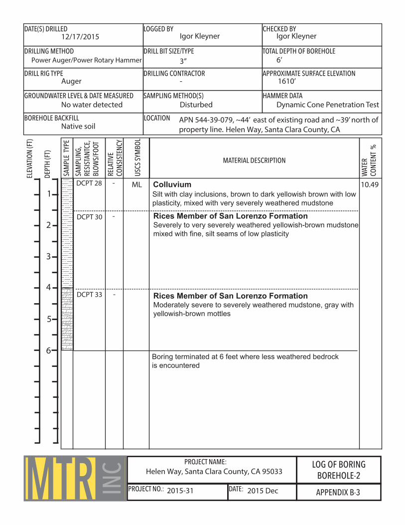
LOG OF BORINGBOREHOLE-2
DATE(S) DRILLED LOGGED BY CHECKED BY
DRILLING METHOD DRILL BIT SIZE/TYPE TOTAL DEPTH OF BOREHOLE
DRILL RIG TYPE DRILLING CONTRACTOR APPROXIMATE SURFACE ELEVATION
GROUNDWATER LEVEL & DATE MEASURED SAMPLING METHOD(S) HAMMER DATA
BOREHOLE BACKFILL LOCATION
WAT
ER
CON
TENT
%
SAM
PLE
TYPE
SAM
PLIN
G, R
ESIS
TANT
CE,
BLO
WS/
FOOT
REL
ATIV
E
CONS
ISTE
NCY
USC
S SY
MBO
L
MATERIAL DESCRIPTION
ELEV
ATIO
N (F
T)
DEPT
H (F
T)
MTR INC
12/17/2015 Igor Kleyner Igor Kleyner
Power Auger/Power Rotary Hammer 3” 6’
Auger - 1610’
No water detected Disturbed Dynamic Cone Penetration Test
Native soil Helen Way, Santa Clara County, CA
10.49
2015 Dec2015-31
Helen Way, Santa Clara County, CA 95033
DCPT 30 -
3
2
1
Boring terminated at 6 feet where less weathered bedrockis encountered
APN 544-39-079, ~44’ east of existing road and ~39’ north ofproperty line.
4
5
6
Colluvium
Rices Member of San Lorenzo FormationSeverely to very severely weathered yellowish-brown mudstonemixed with fine, silt seams of low plasticity
Rices Member of San Lorenzo FormationModerately severe to severely weathered mudstone, gray withyellowish-brown mottles
Silt with clay inclusions, brown to dark yellowish brown with lowplasticity, mixed with very severely weathered mudstone
ML-
-
DCPT 28
DCPT 33

PROJECT NAME:
PROJECT NO.: DATE: APPENDIX B-4
LOG OF BORINGTRENCH-1
DATE(S) DRILLED LOGGED BY CHECKED BY
DRILLING METHOD DRILL BIT SIZE/TYPE TOTAL DEPTH OF BOREHOLE
DRILL RIG TYPE DRILLING CONTRACTOR APPROXIMATE SURFACE ELEVATION
GROUNDWATER LEVEL & DATE MEASURED SAMPLING METHOD(S) HAMMER DATA
BOREHOLE BACKFILL LOCATION
WAT
ER
CON
TENT
%
SAM
PLE
TYPE
SAM
PLIN
G, R
ESIS
TANT
CE,
BLO
WS/
FOOT
REL
ATIV
E
CONS
ISTE
NCY
USC
S SY
MBO
L
MATERIAL DESCRIPTION
ELEV
ATIO
N (F
T)
DEPT
H (F
T)
MTR INC
12/18/2015 Igor Kleyner Igor Kleyner
Power Auger/Power Rotary Hammer 3” 3.5’
Auger - 1610’
No water detected Disturbed Dynamic Cone Penetration Test
Native soil Helen Way, Santa Clara County, CA
10.49
2015 Dec2015-31
Helen Way, Santa Clara County, CA 95033
3
2
1
Trench terminated at 3.5 feet where less weathered bedrockis encountered
APN 544-39-079, ~67’ SE from existing road and ~23’ NE fromproperty line.
4
5
6
Rices Member of San Lorenzo FormationSeverely to very severely weathered yellowish-brown mudstonemixed with fine, silt seams of low plasticity
Rices Member of San Lorenzo FormationModerately severe to severely weathered mudstone, gray withyellowish-brown mottles
DCPT 30
DCPT 32

PROJECT NAME:
PROJECT NO.: DATE: APPENDIX C-1
KEY TO BEDROCK DESCRIPTIONSMTR IN
C
WEATHERINGFRESH
ROCK FRESH, CRYSTALS BRIGHT, FEW JOINTS MAY SHOW SLIGHT STAIN-ING. ROCK RINGS UNDER HAMMER IF CRYSTALLINE.
VERY SLIGHTROCK GENERALLY FRESH, JOINTS STAINED, SOME JOINTS MAY SHOW
THIN CLAY COATINGS, CRYSTALS IN BROKEN FACE SHOW BRIGHT. ROCK RINGS UNDER HAMMER IF CRYSTALLINE.
SLIGHTROCK GENERALLY FRESH, JOINTS STAINED, AND DISCOLORATION
EXTENDS INTO ROCK UP TO 1 INCH. JOINTS MAY CONTAIN CLAY. IN GRANITOID ROCKS SOME OCCASIONAL FELDSPAR CRYSTALS ARE DULL
AND DISCOLORED. CRYSTALLINE ROCKS RING UNDER HAMMER.
MODERATESIGNIFICANT PORTIONS OF ROCK SHOW DISCOLORATION AND WEATH-
ERING EFFECTS. IN GRANITOID ROCKS, MOST FELDSPARS ARE DULL AND DISCOLORED; SOME ARE CLAYEY. ROCK HAS DULL SOUND UNDER HAMMER AND SHOWS SIGNIFICANT LOSS OF STRENGTH AS COMPARED
WITH FRESH ROCK.
MODERATELY SEVEREALL ROCK EXCEPT QUARTZ DISCOLORED OR STAINED. IN GRAINED
ROCKS, ALL FELDSPARS DULL AND DISCOLORED AND MAJORITY SHOW KAOLINIZATION. ROCK SHOWS SEVERE LOSS OF STRENGTH AND CAN BE EXCAVATED WITH GEOLOGIST’S PICK. ROCK GOES “CLUNK” WHEN
STRUCK.
SEVEREALL ROCK EXCEPT QUARTZ DISCOLORED OR STAINED. ROCK “FABRIC” CLEAR AND EVIDENT BUT REDUCED IN STRENGTH TO STRONG SOIL.
IN GRANITOID ROCKS, ALL FELDSPARS KAOLINIZED TO SOME EXTENT. SOME FRAGMENTS OF STRONG ROCK USUALLY LEFT.
VERY SEVEREALL ROCK EXCEPT QUARTS DISCOLORED AND STAINED. ROCK
“FABRIC” DISCERNIBLE, BUT MASS EFFECTIVELY REDUCED TO “SOIL” WITH ONLY FRAGMENTS OF STRONG ROCK REMAINING.
COMPLETEROCK REDUCED TO “SOIL”. ROCK FABRIC NOT DISCERNIBLE OR
DISCERNIBLE ONLY IN SMALL SCATTERED LOCATIONS. QUARTZ MAY BE PRESENT AS DIKES OR STRINGERS.
HARDNESSVERY HARD
CANNOT BE SCRATCHED WITH KNIFE OR SHARP PICK. HAND SPECIMENS REQUIRES SEVERAL HARD BLOWS OF GEOLOGIST’S HAMMER.
HARDCAN BE SCRATCHED WITH KNIFE OR PICK ONLY WITH DIFFICULTY.
HARD BLOW OF HAMMER REQUIRED TO DETACH HAND SPECIMEN.
MODERATELY HARDCAN BE SCRATCHED WITH KNIFE OR PICK. GOUGES OR GROOVES TO 1/4 INCH DEEP CAN BE EXCAVATED BY HARD BLOW OF POINT OF A GEOLO-GIST’S PICK. HARD SPECIMEN CAN BE DETACHED BY MODERATE BLOW.
MEDIUMCAN BE GROOVED OR GOUGED 1/16 INCH DEEP BY FIRM PRESSURE ON
KNIFE OR PICK POINT. CAN BE EXCAVATED IN SMALL CHIPS TO PIECES ABOUT 1 INCH MAXIMUM SIZE BY HARD BLOWS OF THE POINT OF A
GEOLOGIST’S PICK.
SOFTCAN BE GOUGED OR GROOVED READILY WITH KNIFE OR PICK POINT. CAN BE EXCAVATED IN CHIPS TO PIECES SEVERAL INCHES IN SIZE BY MODER-ATE BLOWS OF A PICK POINT. SMALL THINK PIECES CAN BE BROKEN BY
FINGER PRESSURE.
VERY SOFTCAN BE CARVED WITH KNIFE. CAN BE EXCAVATED READILY WITH POINT
OF PICK. PIECES 1 INCH OR MORE IN THICKNESS CAN BE BROKEN WITH FINGER PRESSURE. CAN BE SCRATCHED READILY BY FINGERNAIL.
JOINT BEDDING AND FOLIATION SPACINGSPACING JOINTS
LESS THAN 2 IN.2 IN. TO 1 FT.1 FT. TO 3 FT.
3 FT. TO 10 FT.MORE THAN 10 FT.
VERY CLOSECLOSE
MODERATELY CLOSEWIDE
VERY WIDE
BEDDING & FOLIATIONVERY THIN
THINMEDIUM
THICKVERY THICK
ROCK QUALITY DESIGNATOR (RQD)RQD, AS A PERCENTAGE
EXCEEDING 9090 TO 7575 TO 5050 TO 25
LESS THAN 25
DESCRIPTOREXCELLENT
GOODFAIR
POOR VERY POOR
2015 Dec2015-31
Helen Way, Santa Clara County, CA 95033

PROJECT NAME:
PROJECT NO.: DATE: APPENDIX C-2
UNIFIED SOIL CLASSIFICATION SYSTEMMTR IN
C
PRIMARY DIVISIONSCOARSE
GRAINED SOILS
(<50% FINES)
FINE GRAINED
SOILS(>50% FINES)
GRAVEL
SAND
CLEAN GRAVEL(<5% FINES)
SILT AND CLAYLIQUID LIMIT < 50%
GRAVEL W/ FINES
CLEAN SAND(<5% FINES)
SAND W/ FINES
SILT AND CLAYLIQUID LIMIT > 50%
HIGHLY ORGANIC SOILS
SOIL TYPEGW
GP
GM
GC
SW
SP
SM
SC
ML
CL
OL
MH
CH
OH
Pt
SECONDARY DIVISIONS
Inorganic clays of low to medium plasticity, lean clays.
Organic silts and organic clays of low plasticity.
Inorganic clays of high plasticity, fat clays.
Organic clays of medium to high plasticity, organic silts.
Peat and other highly organic soils.
RELATIVE DENSITY
SAND & GRAVEL BLOWS/FOOT*VERY LOOSE
LOOSEMEDIUM DENSE
DENSEVERY DENSE
0 TO 44 TO 10
10 TO 3030 TO 50OVER 50
CONSISTENCY
SILT & CLAY STRENGTH^VERY SOFT
SOFTFIRMSTIFF
VERY STIFFHARD
0 TO 0.250.25 TO 0.5
0.5 TO 11 TO 22 TO 4
OVER 4
BLOWS/FOOT*0 TO 22 TO 4 4 TO 8
8 TO 1616 TO 32OVER 32
GRAIN SIZES
BOULDERS COBBLES SILT & CLAYGRAVEL SAND
COARSE FINE COARSE MEDIUM FINE
SIEVE OPENINGS U.S. STANDARD SERIES SIEVE
12” 3” 3/4” 4 10 40 200
CLASSIFICATION IS BASED ON THE UNIFIED SOIL CLASSIFICATION SYSTEM; FINES REFER TO SOIL PASSING A NO. 200 SEIVE.
*STANDARD PENETRATION TEST (SPT) RESISTANCE, USING A 140 POUND HAMMER FALLING 30 INCHES ON A 2 INCH OD SPLIT SPOON SAMPLER; BLOW COUNTS FOR COARSE-GRAINED SOILS HAVE BEEN STANDARDIZED TO SPT COUNTS BY FACTORS OF 0.8 AND0.7 FOR THE 2.5-INCH OD AND 3.0-INCH OD SAMPLERS, RESPECTIVELY.
^SHEAR STRENGTH IN TONS/SQ. FT. AS ESTIMATED BY SPT RESISTANCE, FIELD AND LABORATORY TESTS, AND/OR VISUAL OBSERVATION.
Helen Way, Santa Clara County, CA 95033
2015 Dec2015-31

Report Title
Building Code Reference Document
Site Coordinates
Site Soil Classification
Risk Category
Design Maps Summary ReportUser–Specif ied Input
Project No. 2015-31: Helen Way, Los Gatos, CA.Wed January 13, 2016 22:33:11 UTC
ASCE 7-10 Standard(which utilizes USGS hazard data available in 2008)
37.15499°N, 121.987°W
Site Class D – “Stiff Soil”
I/II/III
USGS–Provided Output
SS = 2.553 g SMS = 2.553 g SDS = 1.702 g
S1 = 1.226 g SM1 = 1.839 g SD1 = 1.226 g
For information on how the SS and S1 values above have been calculated from probabilistic (risk-targeted) anddeterministic ground motions in the direction of maximum horizontal response, please return to the application andselect the “2009 NEHRP” building code reference document.
For PGAM, TL, CRS, and CR1 values, please view the detailed report.
PROJECT NAME:
PROJECT NO.: DATE: APPENDIX D-1
USGS SEISMICDESIGN REPORTMTR IN
C
2015 Dec2015-31
Helen Way, Santa Clara County, CA 95033
From Figure 221 [1]
From Figure 222 [2]
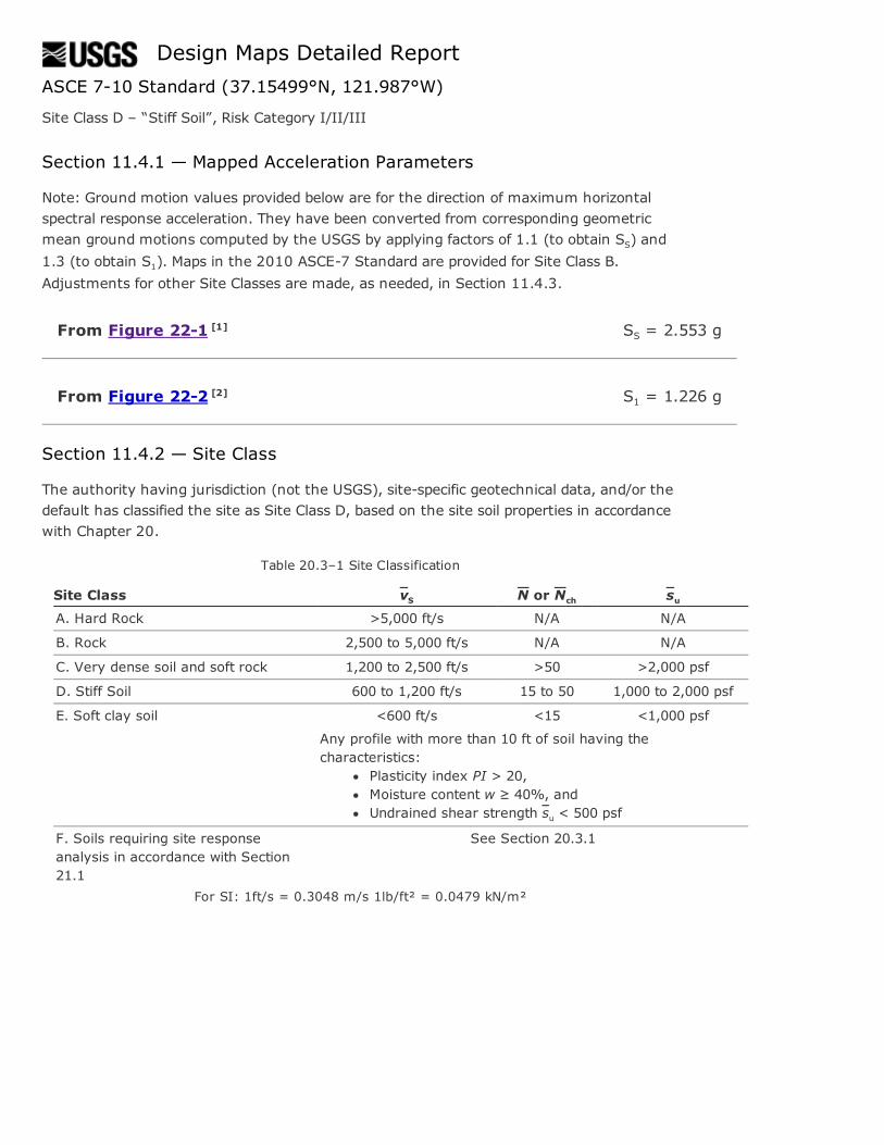
Design Maps Detailed ReportASCE 710 Standard (37.15499°N, 121.987°W)
Site Class D – “Stiff Soil”, Risk Category I/II/III
Section 11.4.1 — Mapped Acceleration Parameters
Note: Ground motion values provided below are for the direction of maximum horizontalspectral response acceleration. They have been converted from corresponding geometricmean ground motions computed by the USGS by applying factors of 1.1 (to obtain SS) and1.3 (to obtain S1). Maps in the 2010 ASCE7 Standard are provided for Site Class B.Adjustments for other Site Classes are made, as needed, in Section 11.4.3.
SS = 2.553 g
S1 = 1.226 g
Section 11.4.2 — Site Class
The authority having jurisdiction (not the USGS), sitespecific geotechnical data, and/or thedefault has classified the site as Site Class D, based on the site soil properties in accordancewith Chapter 20.
Table 20.3–1 Site Classification
Site Class vS N or Nch suA. Hard Rock >5,000 ft/s N/A N/A
B. Rock 2,500 to 5,000 ft/s N/A N/A
C. Very dense soil and soft rock 1,200 to 2,500 ft/s >50 >2,000 psf
D. Stiff Soil 600 to 1,200 ft/s 15 to 50 1,000 to 2,000 psf
E. Soft clay soil <600 ft/s <15 <1,000 psf
Any profile with more than 10 ft of soil having thecharacteristics:
Plasticity index PI > 20,Moisture content w ≥ 40%, andUndrained shear strength su < 500 psf
F. Soils requiring site responseanalysis in accordance with Section21.1
See Section 20.3.1
For SI: 1ft/s = 0.3048 m/s 1lb/ft² = 0.0479 kN/m²
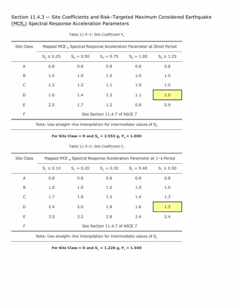
Section 11.4.3 — Site Coefficients and Risk–Targeted Maximum Considered Earthquake(MCER) Spectral Response Acceleration Parameters
Table 11.4–1: Site Coefficient Fa
Site Class Mapped MCE R Spectral Response Acceleration Parameter at Short Period
SS ≤ 0.25 SS = 0.50 SS = 0.75 SS = 1.00 SS ≥ 1.25
A 0.8 0.8 0.8 0.8 0.8
B 1.0 1.0 1.0 1.0 1.0
C 1.2 1.2 1.1 1.0 1.0
D 1.6 1.4 1.2 1.1 1.0
E 2.5 1.7 1.2 0.9 0.9
F See Section 11.4.7 of ASCE 7
Note: Use straight–line interpolation for intermediate values of SS
For Site Class = D and SS = 2.553 g, Fa = 1.000
Table 11.4–2: Site Coefficient Fv
Site Class Mapped MCE R Spectral Response Acceleration Parameter at 1–s Period
S1 ≤ 0.10 S1 = 0.20 S1 = 0.30 S1 = 0.40 S1 ≥ 0.50
A 0.8 0.8 0.8 0.8 0.8
B 1.0 1.0 1.0 1.0 1.0
C 1.7 1.6 1.5 1.4 1.3
D 2.4 2.0 1.8 1.6 1.5
E 3.5 3.2 2.8 2.4 2.4
F See Section 11.4.7 of ASCE 7
Note: Use straight–line interpolation for intermediate values of S1
For Site Class = D and S1 = 1.226 g, Fv = 1.500
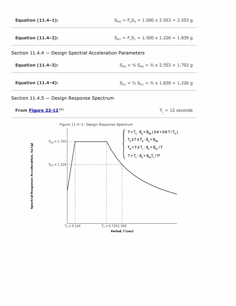
Equation (11.4–1):
Equation (11.4–2):
Equation (11.4–3):
Equation (11.4–4):
From Figure 2212 [3]
SMS = FaSS = 1.000 x 2.553 = 2.553 g
SM1 = FvS1 = 1.500 x 1.226 = 1.839 g
Section 11.4.4 — Design Spectral Acceleration Parameters
SDS = ⅔ SMS = ⅔ x 2.553 = 1.702 g
SD1 = ⅔ SM1 = ⅔ x 1.839 = 1.226 g
Section 11.4.5 — Design Response Spectrum
TL = 12 seconds
Figure 11.4–1: Design Response Spectrum

Section 11.4.6 — RiskTargeted Maximum Considered Earthquake (MCER) ResponseSpectrum
The MCER Response Spectrum is determined by multiplying the design response spectrum aboveby 1.5.

From Figure 227 [4]
Equation (11.8–1):
From Figure 2217 [5]
From Figure 2218 [6]
Section 11.8.3 — Additional Geotechnical Investigation Report Requirements for SeismicDesign Categories D through F
PGA = 0.980
PGAM = FPGAPGA = 1.000 x 0.980 = 0.98 g
Table 11.8–1: Site Coefficient FPGA
SiteClass
Mapped MCE Geometric Mean Peak Ground Acceleration, PGA
PGA ≤ 0.10 PGA = 0.20 PGA = 0.30 PGA = 0.40 PGA ≥ 0.50
A 0.8 0.8 0.8 0.8 0.8
B 1.0 1.0 1.0 1.0 1.0
C 1.2 1.2 1.1 1.0 1.0
D 1.6 1.4 1.2 1.1 1.0
E 2.5 1.7 1.2 0.9 0.9
F See Section 11.4.7 of ASCE 7
Note: Use straight–line interpolation for intermediate values of PGA
For Site Class = D and PGA = 0.980 g, FPGA = 1.000
Section 21.2.1.1 — Method 1 (from Chapter 21 – SiteSpecific Ground Motion Procedures forSeismic Design)
CRS = 0.933
CR1 = 0.892
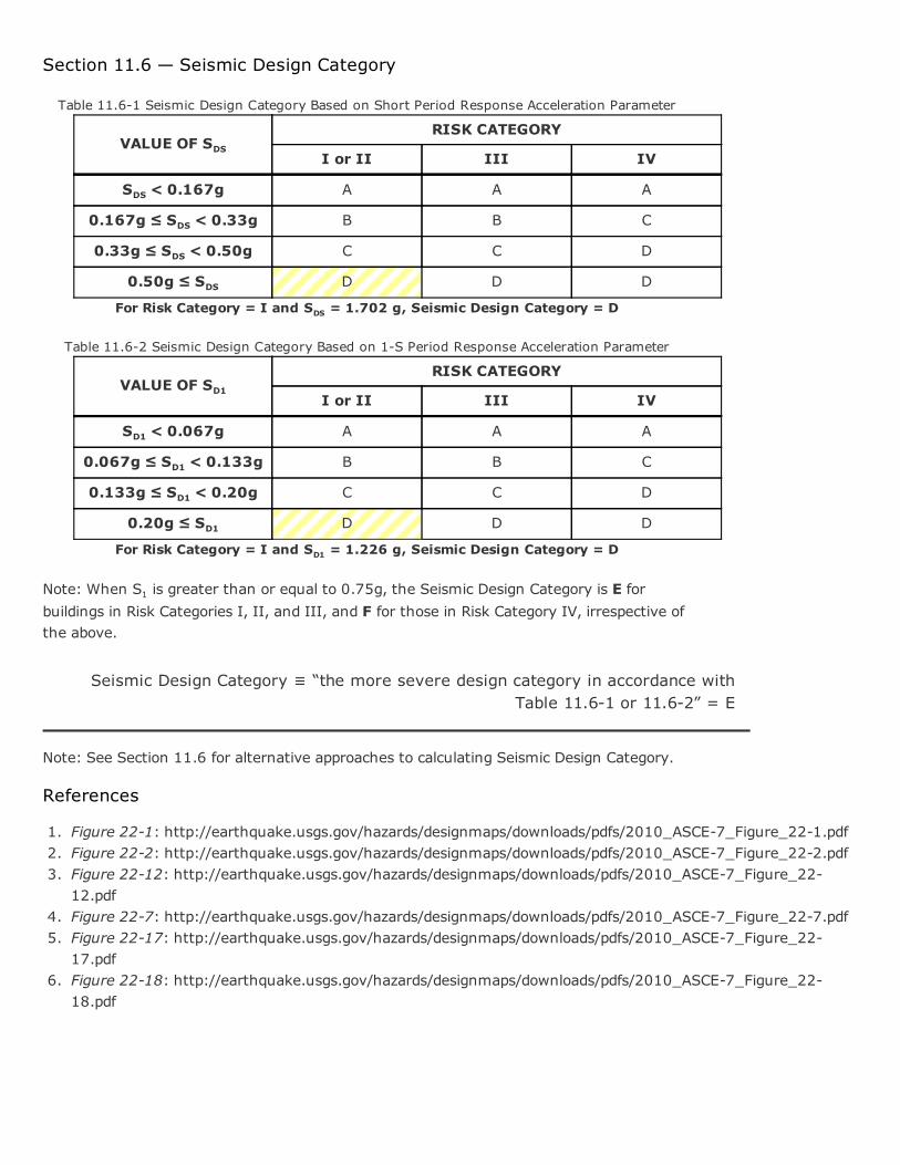
Section 11.6 — Seismic Design Category
Table 11.61 Seismic Design Category Based on Short Period Response Acceleration Parameter
VALUE OF SDSRISK CATEGORY
I or II III IV
SDS < 0.167g A A A
0.167g ≤ SDS < 0.33g B B C
0.33g ≤ SDS < 0.50g C C D
0.50g ≤ SDS D D D
For Risk Category = I and SDS = 1.702 g, Seismic Design Category = D
Table 11.62 Seismic Design Category Based on 1S Period Response Acceleration Parameter
VALUE OF SD1RISK CATEGORY
I or II III IV
SD1 < 0.067g A A A
0.067g ≤ SD1 < 0.133g B B C
0.133g ≤ SD1 < 0.20g C C D
0.20g ≤ SD1 D D D
For Risk Category = I and SD1 = 1.226 g, Seismic Design Category = D
Note: When S1 is greater than or equal to 0.75g, the Seismic Design Category is E forbuildings in Risk Categories I, II, and III, and F for those in Risk Category IV, irrespective ofthe above.
Seismic Design Category ≡ “the more severe design category in accordance withTable 11.61 or 11.62” = E
Note: See Section 11.6 for alternative approaches to calculating Seismic Design Category.
References
1. Figure 221: http://earthquake.usgs.gov/hazards/designmaps/downloads/pdfs/2010_ASCE7_Figure_221.pdf2. Figure 222: http://earthquake.usgs.gov/hazards/designmaps/downloads/pdfs/2010_ASCE7_Figure_222.pdf3. Figure 2212: http://earthquake.usgs.gov/hazards/designmaps/downloads/pdfs/2010_ASCE7_Figure_22
12.pdf4. Figure 227: http://earthquake.usgs.gov/hazards/designmaps/downloads/pdfs/2010_ASCE7_Figure_227.pdf5. Figure 2217: http://earthquake.usgs.gov/hazards/designmaps/downloads/pdfs/2010_ASCE7_Figure_22
17.pdf6. Figure 2218: http://earthquake.usgs.gov/hazards/designmaps/downloads/pdfs/2010_ASCE7_Figure_22
18.pdf