Embed Size (px)
Citation preview
Modern Timber Connectors
f or
Modern Timber Structures
b
Um. V. Raser
A Thesis
Presented to the Faculty
of the
School of Forestry
Oregon State College
In Partial Fulfillment
of the Renuirements for the Degree
Bachelor of Science
Tune 1941
koproved: / ,-) .71
Prossor of Logging En.
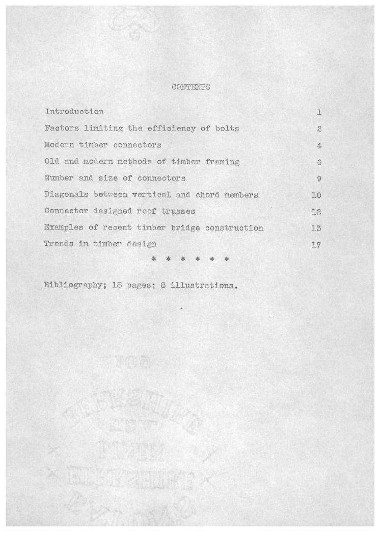
CONTENTS
Introduction 1
Factors limiting the efficiency of bolts 2
Modern timber connectors
Old and modern methods of timber fruiiing 6
Number and size of connectors
Diagonals betvreen vertical and chord members 10
Connector designed roof trusses 12
Examples of recent timber bridge construction 13
Trends in timber design 17
* * * * * *
DibliograDily; 18 pages; 8 illustrations.
i
Introduction
The oldest mechanical devices used for shear con-
nections in timber were wooden pins or dowels, succeeded by
nails and bolts. The major distinction is that nails are
inserted with considerable force and rely on friction for proper action, wheress bolts are installed more or less loosely into Drebored holes, with friction ilaying no im-
nortant part. Therefore, screws and drift bolts, 1thich de-
pend on friction, fall into the ssxae classification as nails. The function of nails, screws, and drift bolts is
the seme as that of rivets in steel construction; hovrever,
they have a disadvantage in that their ratio of slenderness is very high. For instance, whereas a 3/4T1 diameter rivet is associated vith an average Dlate thickness of 3/8", a 7/16"
diameter drift bolt may be used for a timber 3 and l/2' in thickness. In other words, vrhile the ratio of plate thick- ness to rivet dismeter is of an average magnitude of 1/2, the equivalent value for timbers and drift bolts may be 8. For nails it may be as much as 12. This means that nails and drift bolts are subject not only to shear but also to bending, which causes a non-uniform bearing pressure.
This condition together with the effects of shrink- age and checking has defied any pure theoretical attack, and
all safe-working loads have therefore been established by a
large number of tests, and the recommended safe values are based on the proportional-limit load of the connection and
an aDpropriate safety factor. (i)
2
Factors Limiting the Efficiency of Bolts
Nails are ordinarily not accoted in this country
for Drirn.ary load-carrying connections. They are distrusted 1ecause the art of using theni safely is little knovm and not
well established in rn'actice,
Of all connective devices for timbers, bolts have
had the vTidest aDpeal. As a rule they are inserted into holes 1/16" larger than their own diameters. This increases the natural initial yield of timber structures by about 1/32"
for every connection, and therefore a structure viith a large number of bolted connections has a greater unelastic deflec- tion than a nailed or drift-bolted structure. For this rea- son the timber designer alvJays provides his bolted structures with ample cambers and limits the number of joints and sDlices to a minimum.
As mentioned before, nails, screws, and drift- bolts are stressed not only by shear but also in bending.
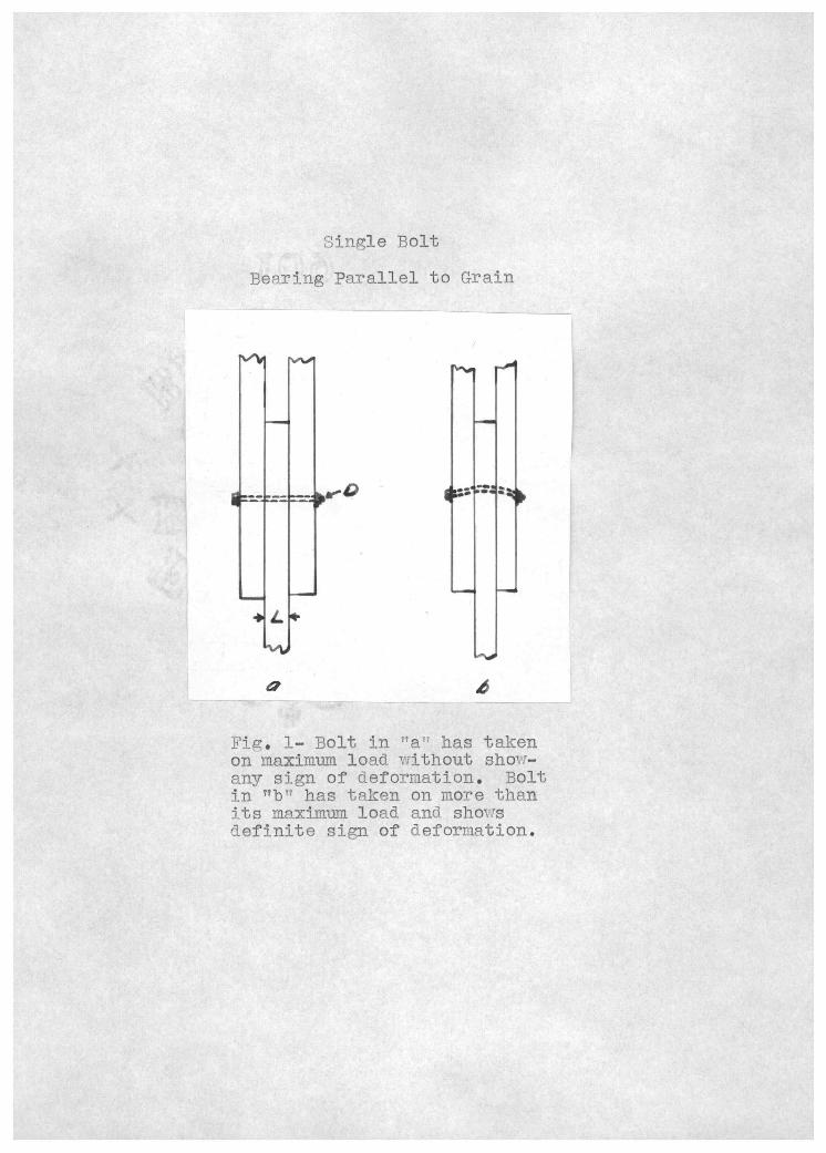
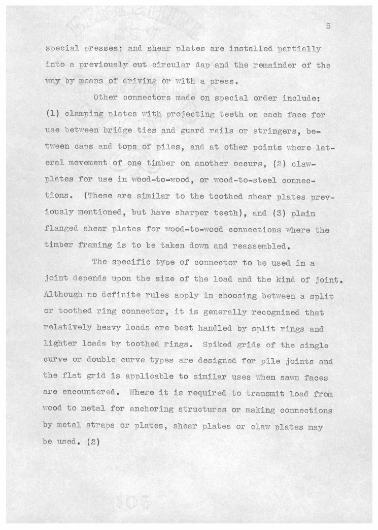
This is true again for bolts. It will be observed from fig. 1 that because flexure is present the actual bearing is dis- tributed over a comparatively small part of the length of the boit, and even within this Dart the full bearing strength of the timber is utilized only at one ooint. Evidently the bolt would. not carry more, even if the timbers wore thicker. In fact its diameter D is already too small compared to the thickness of the center timber L. The ratio L/D in this case
hapDens to be 14, whereas the bearing caacity of the bolt would be exhausted at a ratio of 6 or 7. In other words, in
Single Bolt
Bearing Parallel to Grain
a 4
Fig. 1- Bolt in 'a has taken on maximum load without show- any sign of deformation. Bolt in "b has taken on more than its maximum load and shows definite sign of deformation.
3
hearin9Parallel with the grain, a 1?? bolt reaches its max-
imuni safe load in a 6" timber and cannot Ije credited v.ith
more load in an 8 or loti timber. For the sanie reason the
strength of a 3/16" nBil vTill be fully exploited in a Diank
thickness L of seven tirn.es this diameter D, or i and 5/16".
Inasmuch as nails--to avoid sDlitting of the timber--must
never have .n L/fl ratio of less than 7, they are rated at
their maximum load. Bolts, on the other hand, should i--P
erably be designed with a hearing length smaller than the
critic1 one, and their safe load rill therefore vary .:ith
the L/D ratio.
The sanie situation Drevails in bearing perDendic-
ular to the fiber of the timbers pith the exception that an
increase of L/D beyond 8 actually decreases the proportional
limit load of the connective device (though only slightly).
In other words, the safe load of a lu bolt is somewhat high-
er in an 8" timber than in a lO" timber. There is also this
difference, that the nroortional limit of the bearing stress
across grain increases as D decreases. For instance the safe
load of a 5/Sit bolt in a 2 and 1/2" timber is 1500 lb. par-
allel to the fiber, but only 650 lb. perDendicular to it,
while for a 5/16" bolt it is in both cases 415 lb. Four 5/16"
bolts vreigh the asrie as one s/a" bolt, but they \nrill carry in
any direction 1660 lb. This explains the relative efficiency
of nails and drift bolts within their limitations0 It demon-
strates, on the other hand why, beyond, these l5nitations, the
timber designer was handicapped by want of connective devices
4
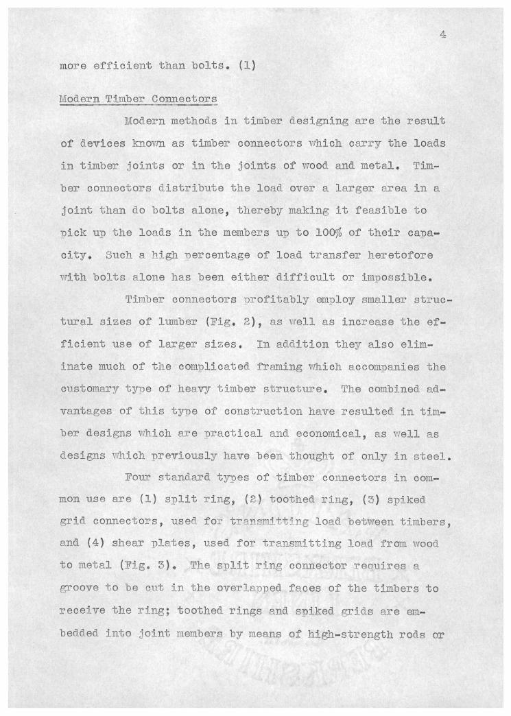
more efficient than bolts. (1)
Modern Timber Connectors
Modern methods in timber ìesigning are the result
of devices knovm as timber connectors rhich carry the loads
in timber joints or in the joints of wood and metal. Tim-
ber connectors distribute the load over a larger area in a
joint than do bolts alone, thereby making it feasible to
Dick UD the loads in the members u to 100% of their caDa-
city. Such a high nercentage of load transfer heretofore
irith bolts alone has been either difficult or imDossible.
TiTher connectors profitably employ smaller struc-
tural sizes of lumber (Fig. 2), as well as increase the ef-
ficient use of larger sizes. In addition they also ehm-
mate much of the complicated framing which accompanies the
customary tyDe of heavy timber structure, The combined ad-
vantages of this tyDe of construction have resulteö in tim-
ber designs which are Dractical and economical, as well as
designs which previously have been thought of only in steel.
Four standard tyDes of timber connectors in coma-
mon use are (1) split ring, (2) toothed ring, () spiked
grid connectors, usefl for transmitting load between timbers,
and (4) shear plates, used for transmitting load from wood
to metal (Fig. 3). The split ring connector reciuires a
groove to be cut in the overlapped faces of the timbers to
receive the ring; toothed rings and spiked grids are em-
bedded into joint members by means of high-strength rods or
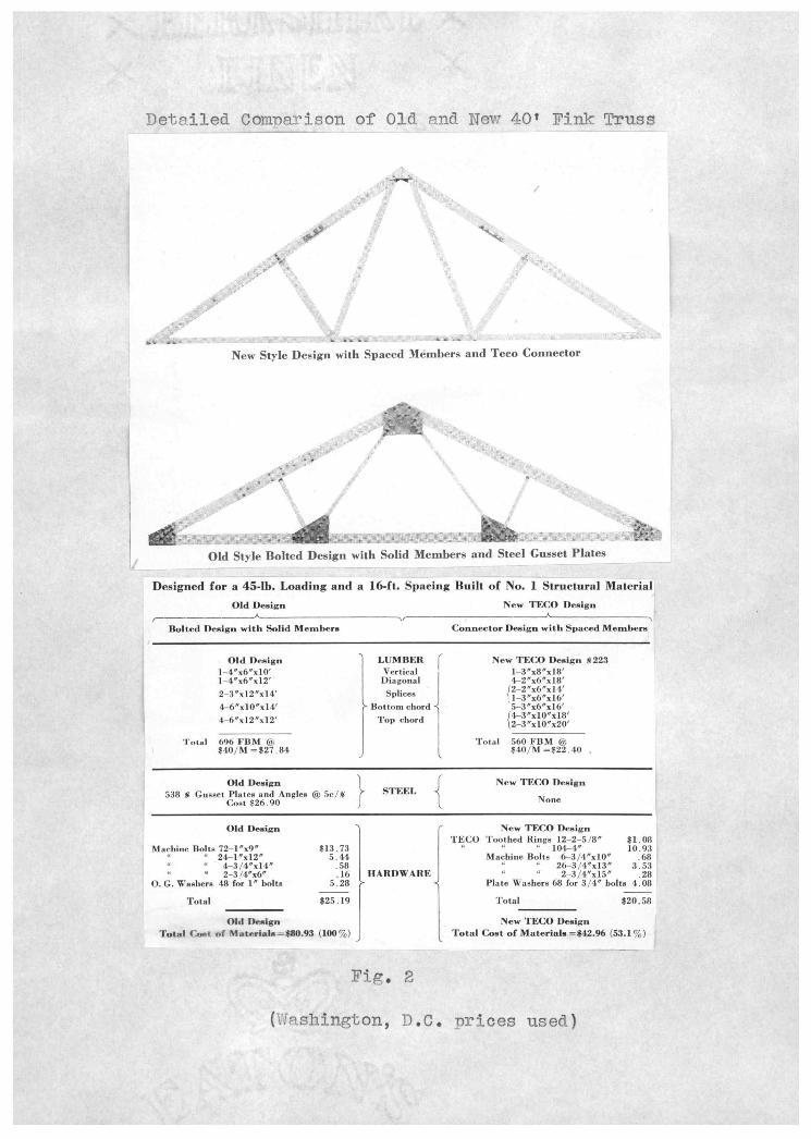
Detailed Conmarison Of Old and New 40' Fink Truss
New Style Design with Spaced Members and Teco Connector
Old Style Bolted Design with Solid Members and Steel Gusset Plates
Designed for a 45-lb. Loading and a 16-ft. Spacing Built of No. i Structural Material Old Dcign New 'l'ECO De.ign
______ Bolted fleign with Solid Members Connector Design with Spaced Members
Old Deaigu LUMBER New TECO Design 223 l4x6exlO Vertical l3ex8xl8 1_4ex6xl2 Diagonal 42ez6ex18 23ex12ex14 Splices 46exlOxl4 Bottom chord 5_3Cx6ex16
Top chord
Tot.I 696 FBM t Total 560 FBM ® $40/M=$27.84 $401M$22.40
Old Deaign 1 1
New TECO De.ign 538 Gusset Plates and Anglea øJ 5c/% ?
STEEL -
None Cost $26.90 _) 1_
Old Design New TECO Design TECO Toothed Rings 12-2-5 /8 $1.08
Machine Bolts 72-15x95 $13.73 104_4e 10.93 24-L'al25 5.44 Machine Boita 3/4aXlOS .68
4.3/45x145 .58 26-3/4zl35 353 a 2-3/4x65 .16 HARDWARE 3/45x155 .28
O. G. Washers 48 for 1' bolts 5.28 Plate Washers 68 for 3/45 bolts 4.08
Total $25.19 Total $20.58
Oid Design New TECO Design Total (ost of Materials =$80.93 (100%) Total Cost of Materials =142.96 (53.1%)
Fig. 2
(,T.shjfltofl, D.C. nrices used)
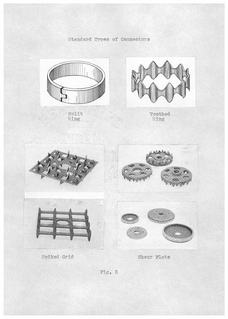
Standard Trres of Connectors
SDlit Ring
Spiked Grid
Fig. 3
Tooth ed jflr
Shear Plate
5
secia1 rresses; end shear ìlates are installed Dartially
into a Dreviously cut circular daD and. the remainder of the
Tay by means of drivin or with a press.
Other connectors made on special order include:
(1) cleinDing Diates with projecting teeth on each face for
use between bridge ties and guard relis or stringers, be-
tween caes and toDs of piles, and at other points where lat-
eral movement of one timber on another occurs, (2) claw-
nletes for use in wood-to-wood, or wood-to-steel connec-
tions. (These are similar to the toothed shear plates Trev-
iously mentioned, but have sharper teeth), and (3) plain
flanged shear Dlates for wood_to_wood connections :rhere the
timber framing is to be taken down and reassembled.
The sDecific type of connector to he used in a
joint deDends upon the size of the load and the kind of joint.
Although no definite rules aDDly in choosing between a split
or toothed ring connector, it is generally recognized that
relatively heavy loads are best handled by split rings and
lighter loads by toothed rings. Spiked grids of the single
curve or double curve types are designed for pile joints and
the flat grid is arn)licable to similar uses when srnJn faces
are encountered. There it is required to transmit load from
wood. to metal for anchoring structures or making connections
by metal straps or plates, shear plates or claw Dlates may
be used. (2)
Old and. Modern Methods of Timber Framin
Connections in timber framing
made by lapping the ends of the several
other. Contact areas are thus obtained
transmitted from one member to another.
contact, it is possible to develop vrith
to 60% of the allo:Table 1forking load of
By use of timber connectors a
6
customarily are
members over each
in rhich loads are
In these areas of
bolts only from 40
the members.
îound of good struc-
tural timber will do in general the same Tork that can be
exoected from a pound of steel. The greatly increased
strength secured at crucial points is of such Drirne engin-
eering importance as frequently to change both the methods
of design and cost asDects of many structural types. Tim-
ber can now be used economically for types of structures for
'hich it has not formerly been considered, and timber struc-
tures can now be designed for wider spans and heavier loads
than before.
As comnared with the earlier types of notched or
hand-fitted joints, timber connectors greatly reduce labor
costs. As comîared with joint details in which timbers are
bolted to steel gussets, the connectors are lighter and
cheaper, not only in weight of metal used, but also in the
amount of timber required. for a given load and in the assen-
bly labor required. Design features are also greatly simp-
lified because v.rith the connectors the strength of joints
can be Quickly and accurately computed. (2)
77
The advantages of factory fabrication were soon
realized; shoDs were ecuipp ed with modern powerdriven saws,
boring machines and other simple labor-saving devices, and
today structural units in wood are Drefabricated and shipDed
to construction jobs. All shaping, cutting, and boring is
done in the shop so that exDensive hand labor is suplanted
almost entirely by modern mechanical devices.
Units may be shipped assembled or knocked down.
When not assembled, each Diece is marked for erection, the
connectors may be inserted at the shoD, and only the niacing
of the bolts in prebored holes is required at the job. This
rocedure, of course, is similar to erection methods with
metal.
Costs have thus been reduced not only through more
efficient fabrication methods, but also, as has been mentioned
before, through a saving in the volume of wood required for a
structure. These are obvious economies, In addition, how-
ever, are the opportunities for proner selection of snecies
and grades at the fabricating shop, exnert technical suner-
vision, and elimination of waste material at the niant and
consequent saving in freight charges.
For construction purposes where cuick erection and
dismantling are required, the modern connectors have nroved
esnecially valuable. In military as well as civilian oper-
ations they have been used in construction of barracks,
bridges, trestles, and numerous other structures.
Ali the advantages mentioned have been demonstrated
[1
in Euirooe, :rhere in many resDects conditions for the adoD-
tion of modern wood-construction methods seem much less fa-
vorable than in the United States. Here vro have numerous
soft pines, sDruces, hemlocks, and true firs fully equal to
the EuroDean species used in construction, and in addition
such outstanding structural i.roods as southern yellow Dine
nd Douglas fir, to say nothing of larch, redwood, the ced-
ars, cypress, and oak. Because their superior strength prop-
erties are recognized, some American structurai woods are im-
Dorted by European countries, through special dispensation
in some instances where the general economic policy has been
to favor native secies by actual prohibition of foreign lum-
b er.
Cartinly the conditions that lead. to such impor-
tation are far less favorable than those in the United States.
Also, as a result of exhaustive research by the Forest Prod-
ucts Laboratory, accurate and complete data are available as
to strength proDerties of all commercial American species and
grades. In Europe, engineers have been handicaped by a lack
of complete data on their native woods, Yet, despite this,
modern connectors have gained in popularity abroad, Moreover,
in the United States, the ratio of cost of labor to cost of
material on a construction job is far greater than in Europe
and in consequence the possibilities of savings by increas-
ing the efficiency of labor are correspondingly greater.
Furthermore, local common labor may be employed in erection
with modern timber connectors. (3)

Number and Size of Connectors
ifter the type of connector to use in the struc-
tiire is decided upon, it remains, in the case of the snilt
rings and toothed rings, to determine the number and size of
the connectors vrhich best apply. The choice of connector
size is based to a large extent on the following consider-
ations:
i. Loaa-carrying caDacity of the connector as influ- enced by direction of load with reference to grain in the wood, grade of timber, and edge and end mar- gins;
2. Load to be carried;
3. Relative occurrence of similar types of joints in the structure;
4. Available overlanDed surface area in the joints;
5. Number of rings in a single joint.
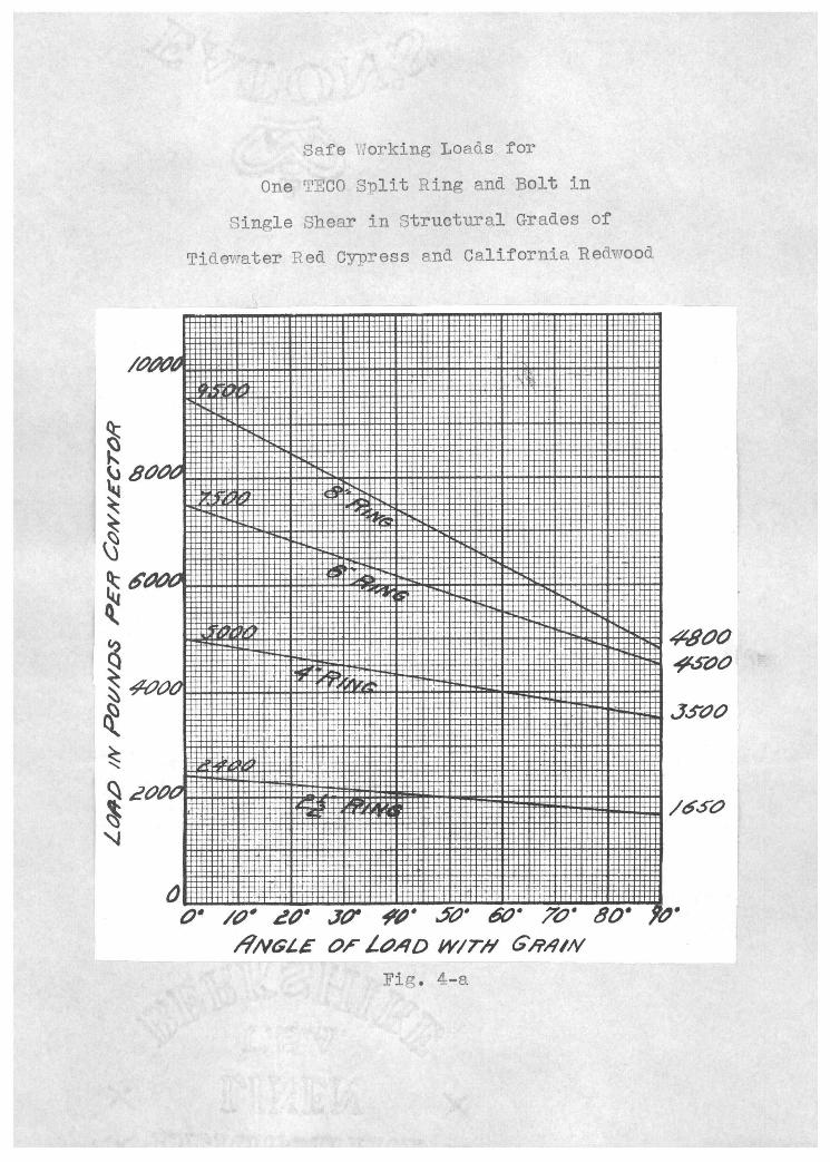
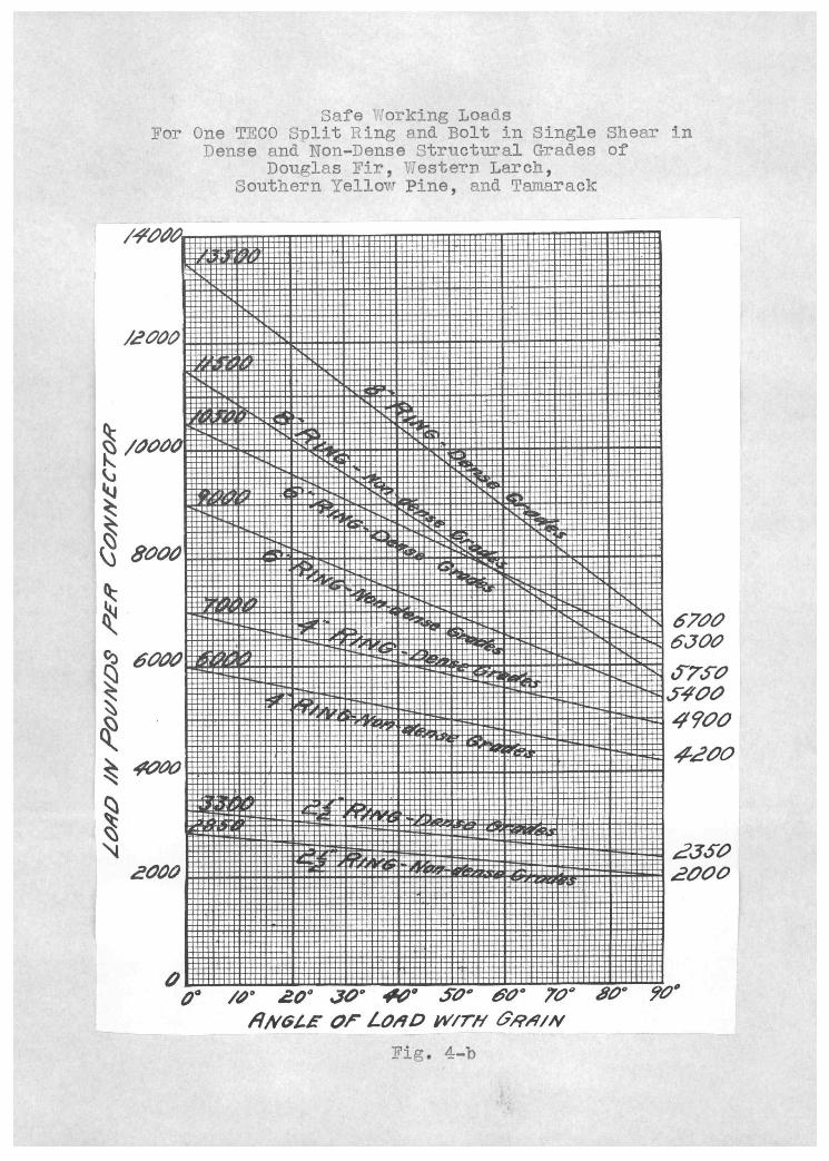
Safe working loads assigned to timber connectors
for the different conditions listed in No. 1 above, may be
read from the load charts in the t?ffanua1 of Timber Connector
Construction" (Fig. 4 a and b). The unit load per connec-
tor, divided into the total load, will give the number of
connectors reqnired. The specific size or sizes of connec-
tors t,o emnloy in timber design will be determined by the
types of joints. If the load in a large percentage of the
joints can be carried effectively by a single ring size on
one or more bolts, this factor will greatly influence the
size recommended for the remainder of the structure. A
single connector size, especially the split ring tyDe, used
in a design, keens the cost at a minimum, since it means
±ewer tools to buy and fewer to handle during fabrication.
Different sizes of rings in a structure, on the other hand,
are soraetirnes quite advantageous for large trusses or for a
large oh where parts are shot fabricated uith plenty of
equipment available and their use need. not be ruled out un-
less it is evident that a single size will serve effectively.
The overlapped area in timber ioints may also in-
fluence connector size by permitting sufficient enö. and edge
margins for a single bolt with a large ring, but not flro-
viding proper spacing for two or more bolts with smaller rings
or conversely may provide adequate margins and sDacings for
multiple small rings but not for the larger ones. It should
be noted in this connection that a connectore .. blut with a
single bolt plus connectors the easiest to fabricate
and to assemble. The use of a large number of bolts and small
connectors in a joint is generally not recommended due to the
more complicated joint. However, it may he necessary at times
to avoid the necessity of increasing the size of the structur-
al member in order to provide the required margins, end and
side, for the larger ring. The relative economy of the lar-
ger size ring in the larger timber in such a case should be
weighed against that of the smaller timber and greater number
of rings. (2)
Diagonals Between Vertical and Chord Members
In certain troes of construction, such as Pratt or
Howe trusses, where the diagonal web members are highly
stressed and overiaped area is at a premium, it frequently
1I
haoDens that by D1acin the diagonais between tue vertical
and horizontal members that amDle sace is nrovideã. for con-
nectors. Other aövantages gained from this tyDe of ioint
are that (1) the bottom chord. vthich is in tension does not
need to be the saine thickness as the top chord; (it may be
thinner and. vxier to afford. more sace for the connectors),
(2) a smooth exterior is Dresented by the truss chords; and
(3) the load ner connector in the vertical is increased be-
cause the angle to the grain is now less than g° with the
diagonal to 1iich it is connected. The following descrip-
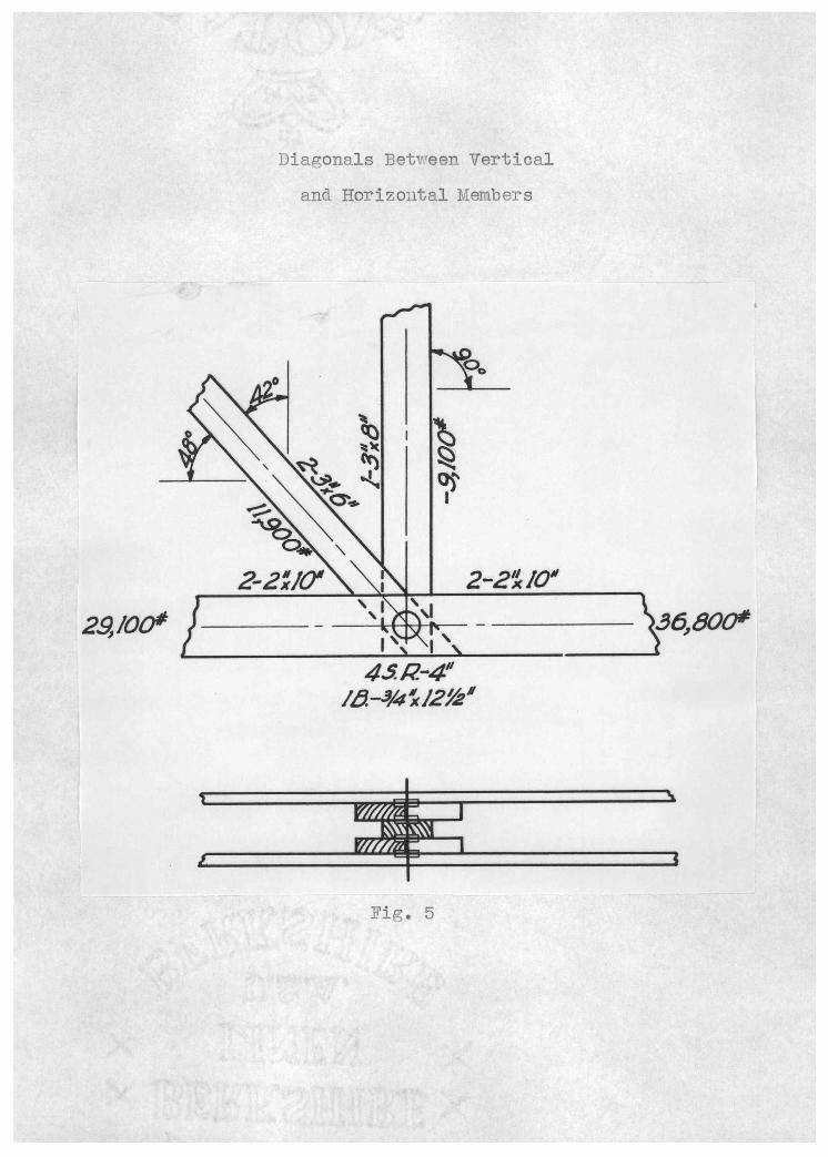
tion demonstrates this type of .ioint (Fig. 5).
Cônditions: Fiat top att Truss Snan 60' Panel spacing 16'-O" c. to c. Total live and dead loads 40 lbs./sa. ft. oint in lower chord
The feature of this joint is that the diagonals
which must transmit the greatest load in the joint ere placed
between the vertical and horizontal members, thereby present-
Ing two faces into which connectors may be placed instead of
one face each, if the diagonals were placed outside the
chords. The load to be transmitted between the diagonals to
the vertical is 9,100 lbs. The allowable connector load for
a 4" split ring acting at an angle of 42° with the grain is
5,150 lbs. Therefore, two connectors, one each side of the
vertical, will more than carry the 9,100 lbs. required.
In the lower chord which is continuous through the
joint, it is necessary only to eliminate the difference be-
tween the stresses on opposite sides of the joint. There-
29,/00'
Diagonals Betvreen Vertical ana Horizontal Members
4. R-4" /-3/4 /21(a'
Fie,. 5

12
fore, the stre to 1e absorbed at the joint is 7,700 lbs.
(36,000 lbs. minus 29,100 lbs.). The allovrable safe load.
capacity or a 4" connector bearing at an angle of 480 to
the grain in non-dense material is 5,000 lbs. Two connec-
tors therefore between the diagonals and. chord. members are
sufficient. Then, since the stress in the vertical is equal
to the vertical component of the diagonals and. the differ-
ence between the two chords' stresses is equal to the hor-
izontal component of the diagonals, and since both the ver-
tical and chord members are directly connected to the diag-
onals, it follows that the connectors sDecified must develop
the stress in the diagonals. (2)
Connector Designed Roof_Trusses
Timber construction is used exclusively in the
shipyard recently completed at Tacoma, VJash., for the
Seattle-Tacoma ShiDbuilding Corooration which has a con-
tract to build five 6,800-ton freighters for the U.S. Mar-
atime commission. The covered area includes 103,200 sq. ft. in a groun of shop buildings doining two shipways that lead. from the plant into Puget Sound..
In the shops are 72 timber trusses with spans of
50 ft. or more; 12 have spans of 130 ft. Fabrication of
trusses began November 1, 1940, was completed December 21
and their erection was finished. the first week in January,
1941. The buildings include a two-story, 130x260-ft. mold
loft; an 84x350-ft. assembly shop; two plate shots each SOx
1.3
150-ft.; a slab shor and. a blacksmith shop, each 50x150-ft.;
and a 50x200-ft. layout shop.
For the most Dart, truss sDacings are 20 to 25-ft.; roofs are designed for a live load of 20 11s./sq. ft. The
roofing proper consists of 2-in. tongue and groove 1anks on
6x12 or 6x14-in. pujlins sDaced 8-ft. on centers. Joints in
byTe trusses ere nade vrith snlit ring connectors, and in the
bowstring trusses all heel plates and metal fastenings are
attached with flush tyie shear plates. For all toD and bot-
tom chords, select structural Douglas fir was specified and
for smaller diagonal IJeb members the gradewas select merch. (4)
Exa.s ont i Bilge onstruct ion
One of the most difficult roblems currently fac-
Ing highway officiels is that of nroviding bridges with a
capacity commensurate with that of the connecting roadways
at a cost that is not prohibitive. Several highway derart- ments have pointed toward at least a partial solution of
this nroblem by building adequate but relatively low cost
wood structures. Modern develouments such as the stress 'ading of
lumber, improved methods of drying to eliminate seasoning
defects, the treatment of Dortions subject to unusual decay
hazards and the many efficient modern times of joint connec-
tions provide preater flexibility in design than has been
possible in wood design of the past.
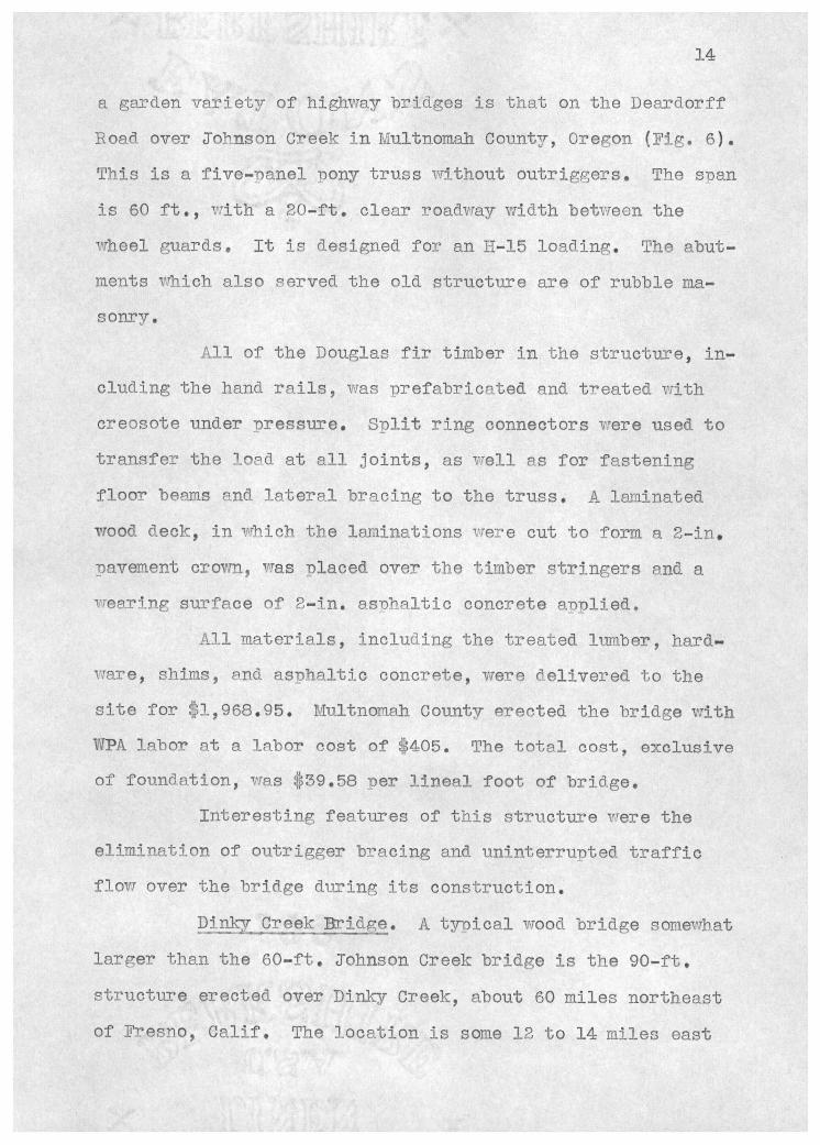
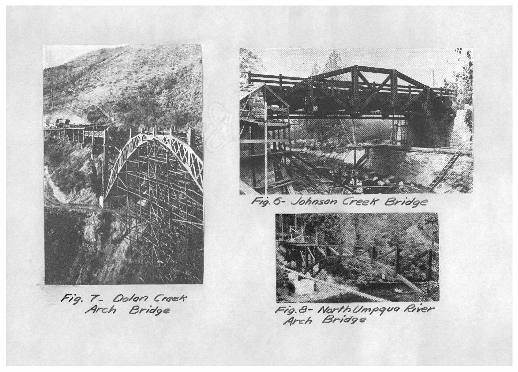
Iohnson Creek Bridge. A well designed example of
14
a garden variety of highway bridges is that on the Dearciorff
Road over onson Creek in Ivlultnomah Countr, Oregon (Fig. 6).
This is a five-panel iony truss without outriggers. The sDan
is 60 ft., with a 20-ft. clear roadway width between the
vrheel guards. It is designed for an II-15 loading. The abut-
raents which also served the old structure are of rubble ma-
sonry.
Ail of the Douglas fir timber in the structure, in- cluding the hand rails, was prefabricnted and treated with
creosote under pressure. Split ring connectors were used to transfer the bed at all joints, as vrell as for fastening floor besms and lateral bracing to the truss. A laminated
wood deck, in thich the laminations were cut to form a 2-in. pavement crovm, was placed over the timber stringers and a
wearing surface of 2-in. asohaltic concrete applied. All materials, including the treated lumber, hard-
ware, shims, end ashaltic concrete, were delivered to the site for l,968.95. Multnoriah County erected the bridge with WPA labor at a labor cost of 4O5. The total cost, exclusive of foundation, was 39.58 oer linea]. foot of bridge.
Interesting features of this structure were the elimination of outrigger bracing and uninterruotec traffic flow over the bridge during its construction.
ptT Creek Bridge. A tynical wood bridge somewhat
larger than the 60-ft. Johnson Creek bridge is the 90-ft. structure erected over Dinky Creek, about 60 miles northeast of ?resno, Calif. The location is some 12 to 14 railes east

15
of the main highway to Huntington Lake, a noDular recre-
ational area at a 5,900-ft. elevation.
The bridge is a factory fabricated through truss
structure designed for an H-15 loading. It has a 20-ft.
roadway and required 38,888 ft. of Douglas fir in its con-
struction. All timbers, exceDt stringers and decking, had
been treated with an 8-lb. creosote and netroleum oil treat-
ment and timber connectors were employed in the truss con-
nections. The
creosoting, and
making the cost
$35.56.
Dolan
3ontract rce for lumber, prefabrication,
hardware deUvered. to the site was $3,201.86,
per lineal foot of roadway without erection
Creek Bridge. It being increasingly real-
ized by builders that timber with modern developments in
connection lends itself well to the arch type of construe-
tion. An excellent exnrnle of this type of bridge is the
Dolan Creek Arch, built of redwood and located. on State Route
57. This structure, about 50 miles south of Monterey, Calif.,
is a three-hinged. timber arch and is but one of the 20 wood
bridges on this coast highway.
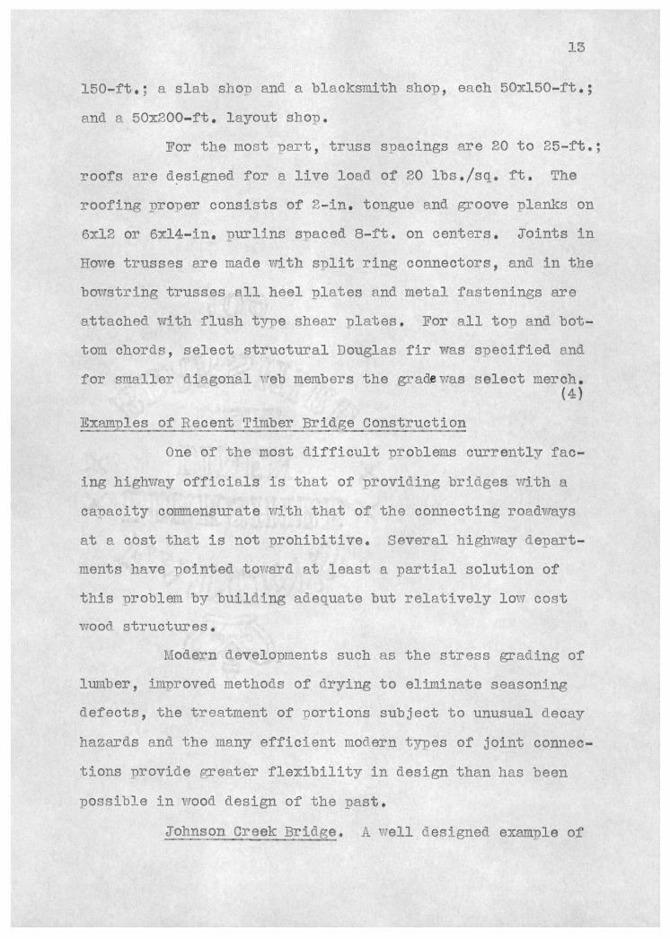
Dolan Creek bridge (Fig. 7), with an over-all length
of 514 ft., has a roadway width of 24 ft. and is made u of a
three-hinge arch span of 180 ft. (60-ft. rise), four 38-ft.
timber girder spans and nine 19-ft. timber trestle bent ap-
proach spans. One end of the structure is on a curve which
has been compensated by super-elevation and the roadway has
a grade of 0.567 percent.
16
An interesting factor in connection with the con-
struction oÍ this bridge is that it was designed to serve
under a 40-ton moving load. This is twice the loading nor-
mally assumed in Cali±ornia bridge design, but was required
because of the freauent movements of 40-ton shovels long
this coast route.
SDlit ring connectors up to B in. in diameter were
used in assembling the arch ribs and the 38-ft. built-up
girders. The successful bid for the whole 514-ft. Dolan
Creek bridge, including excavation, foundations and Diers,
was 67,8?l.00, or $132.00 per linear foot.
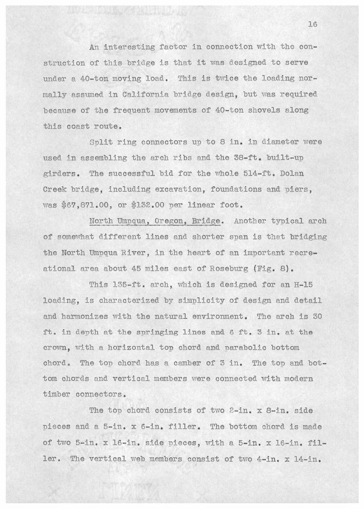
North Dinqua, Oregon, Bridge. Another tyDical arch
of somewhat different lines and shorter sDan is that bridging
the North Umnoua River, in the heart of an important recre-
ational area about 45 railes east of Roseburg (Fig. 8).
This 1.35-ft. arch, which is designed for an H-15
loading, is characterized by simplicity of design and detail
and harmonizes with the natural environment. The arch is 30
ft. in depth at the springing lines and 6 ft. 3 in. at the
crown, with a horizontal top chord and Darabolic bottom
chord. The ton chord has a camber of 3 in. The top and bot-
tom chords and vertical members were connected with modern
timber connectors.
The tOD chord consists of two 2-in. x 8-in. side
Dieces and a 5-in. x 6-in, filler, The bottom chord is made
of two 5-in. x 16-in. side Dieces, with a 5-in. x 16-in. fil-
1er. The vertical web members consist of two 4-in. x 14-in,
E,9. 7-. ¿7/c" C,4 A'ih -4e
C-ee4 5,-he
/9 IP. ,4,-#i, P./9&
1'?
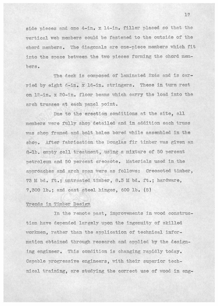
side iecos and. one 4-in, x 14-in. filler Diaced so that the
vertical web nienibers could be fastened to the outside of the
chord members. The diagonals are one-Diece members which fit
into the sDace between the two pieces forming the chord mem-
bers.
The deck is comnosed of laminated 2x4s and is car-
ried by eight 6-in. x 16-in, stringers. These in turn rest
on 12-in. x 20-in, floor beams which carry the load into the
arch trusses a.t each nanel Doint.
Due to the erection conditions at the site, all
members viere fully shop detailed and in addition each truss
was shot framed and bolt holes bored while assembled in the
shop. After fabrication the Douglas fir timber was given an
-1b. empty cell treatment, using a mixture of 0 oercent
petroleum and. 50 percent creosote. Materials used in the
approaches and arch sDan were as follows: Creosoted timber,
73 M bd. ft.; untreated timber, 8.3 M bd. ft ; hardware,
9,300 lb.; and. cast steel hinges, 600 lb. (5)
Trends in Timber Design
In the remote past, improvements in wood construc-
tion have deDended largely upon the ingenuity of skilled
workmen, rather than the amiication of technical infor-
nation obtained through research and applied. by the design-
ing engineer. This condition is changing rapidly today.
Capable progressive engineers, with their superior tech-
nical training, are studying the correct use of wood in eng-
18
meeTing structures &nd modern development in vTood design.
Tuis healthy trend would seem to indicate that, in
the future, as more scientific knowledge of wood is accum-
ulated, and the engineering data on timber become more widely
disseminated, wood will more nearly approach the much wider
usage which its imherent merits as a construction material
justify. (6)
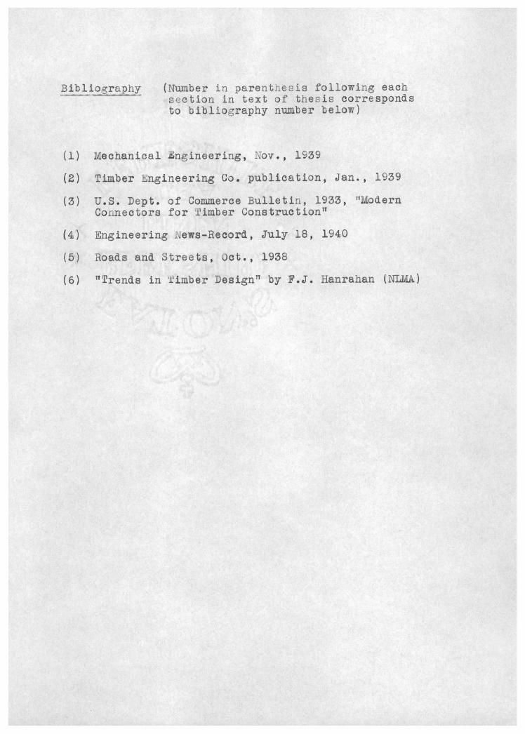
Bibliography (Number in parentresis following each section in text of thesis corresponds to bibliography number below)
(i) Mechanical ngineering, NOV., 1939
(2) Timber ngineering Co. publication, Jan., 1939
(3) U.S. Dept. of Commerce Bulletin, 1933, 'Modern Connectors for iimber Constructiont1
(4) Ingineering ews-Record, July 18, 1940
(5) Roads and. 3treets, Uct., 1938
(6) 'TTrends in limber Designtt by F.J. Hanrahan (NEvIA)