Embed Size (px)
Citation preview
Modern Windmills
The principles are ancient but the materials and the technology ha ve changed. The chief function of modern mills is to generate electricity, thereby conserving fuel for conventional power plants
by Peter M. Moretti and Louis V. Divone
The windmill, which is one of the oldest means of prod ucing mechanical power, might by now
have become a curiosity but for the energy crisis of the 1970's. Because of the interest then in alternatives to petroleum as a source of energy, the windmill came in for a good deal of technological improvement. As a result a number of individual windmills and windmill farms, or arrays of mills, are contributing to the local electricpower system in several countries. The contribution is small now, but one can predict that it will become significant with the inevitable eventual tightening of the petroleum supply and the improving technology of windmills.
The obvious attraction is that wind is free. The equipment is not free, however, and the technology is complex. As any sailor knows, harnessing the wind is not an easy feat. The wind is probably unique among power sources in its random variability. Even though various averaging procedures show daily and seasonal patterns in wind strength, the person who would harness the wind must deal with gusts, lulls and shifts in direction that come unpredictably.
Unpredictability from moment to moment and place to place is not the only problem. The wind's variability also covers a wide range of velocities. Moreover, the effect of velocity is enlarged by the fact that wind force (the amount of push) varies with the square of velocity, whereas the power (the rate at which the wind can be made to do work) varies with the cube of velocity. Hence when a gust reaches eight times the average wind speed, as sometimes happens in a storm, the force of the wind is 64 times the normal value. When the wind speed changes by a factor of two, as it often does, the power varies by a factor of eight.
Wind variability confronts the operator with the technical problems
110
of matching the load to the available power and protecting his mill from gales. The original solution to the first problem, centuries ago, was to make the load adapt to the power source. Threshing or milling took place when wind was available and was suspended when the wind died down. Today's mills are combined with other energy producers, such as an electric utility's generators, to overcome this intermittent operation. The original solution to the problem of gales was to provide for dismantling some of the mill's aerodynamic surfaces, as one would furl sails, in the face of an approaching storm. Modern mills incorporate a variety of mechanisms for letting storm winds blow past without harm.
Wind has a second major characteristic in addition to variability: its diffuseness. It is not a concentrated source of energy. Its drag force on a square meter of surface is quite small at ordinary wind velocities (although it can be very large during storms), and the power of the wind passing through a sq uare meter of area is modestabout on a level with the energy flow of the sun's radiation. When the wind is blowing at a brisk rate of six meters (20 feet) per second, or about 13.4 miles per hour, the energy flux is only about 130 watts per square meter (.016 horsepower per square foot), and not all of that can be extracted by a windmill. When the objective is to generate electricity, these are negligible numbers compared with the levels of power represented by a flowing brook or a domestic fire, not to speak of a fossilfuel power plant. In order to generate a
significant amount of power a windmill must therefore harvest a large cross-sectional area of wind.
The earliest windmills known were in western Asia. They looked like
large paddle wheels partially exposed to and partially shielded from the wind. One ancient mill found on the Persian plateau was built around a vertical axis, suggesting that it developed from a mill operated by draft animals pulling the end of a beam along a circular path. The need for large surfaces to harvest the low specific forces of the wind was met by building up windmill sails out of bundled or woven fibrous reeds.
The antiquity of these windmills is uncertain. One early reference, which is highly ambiguous, suggests a date of about 1700 B.C., more than 1,000 years after the first use of sails on ships. Even if that estimate is correct, windmills must have been scarce during the next 1,000 years. By A.D. 1100, however, crusaders and travelers found windmill technology well established in the Middle East. It is clear that windmills were not in wide use even at that time; the problems presented by the variability and the diffuseness of the wind had not yet been adequately solved.
The variability of the wind could be accepted in applications that allowed for storage of the raw materials and the products, for example in grinding grain and sawing logs. Pumping water for irrigation or swamp drainage also offered some flexibility. Nevertheless, water-driven mills offered more reli-
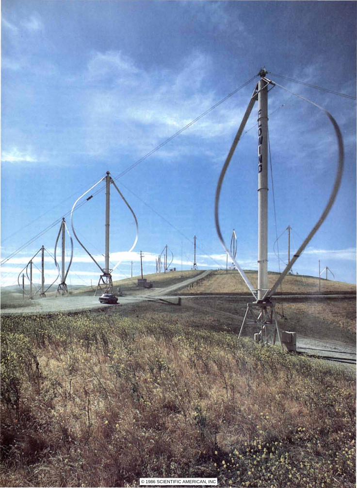
MODERN WINDMILL based on an unconventional concept is the Darrieus turbine,
named for the French engineer J. G. S. Darrieus. He invented the concept in the 1920's, but it was forgotten; workers at the National Research Council in Canada reinvented it in the
1970's. The Darrieus rotor turns on a vertical axis, whereas conventional windmills have a propellerlike, horizontal-axis rotor. This array of Darrieus turbine mills is in California.
© 1986 SCIENTIFIC AMERICAN, INC
© 1986 SCIENTIFIC AMERICAN, INC
able power where they were feasible, and so windmills were likely to be found primarily where water power was not available.
The diffuseness of wind power and the resulting low output of windmills presented a problem that affected all applications and called for new technological solutions. Those solutions had already been developed on sailing ships. Sailors had long since discovered that a vessel will proceed faster when the wind comes from the side than when it comes from behind. The reason is the difference between lift and drag. A considerable aerodynamic lift develops along a sail when wind from the side sweeps across it with a large relative velocity. The push of a tail wind, on the other hand, is reduced to a small relative velocity by the motion of the ship.
Similarly, a windmill based on lift forces can produce several times the output of paddle-wheel blades that are simply dragged along by the same cross-sectional area of wind. Moreover, a mill taking advantage of lift needs less blade material than a mill based on drag. The reason is that lifting blades do not have to cover as much area with their surface; they merely sweep across the wind repeatedly. Finally, the blades rotate faster;
a
.. .. .
: .•.........
' , , ' .
this is an advantage in a mill that has to gear up the shaft speed to enable the load (usually an electric generator in such cases) to run efficiently.
The era of propellerlike windmills utilizing lift forces probably began as mill technology moved westward and met the technology of the sailing ship in the Persian Gulf and the Mediterranean Sea. The loose-sailed windmill rotors still seen on Mediterranean islands bear a clear resemblance to the sail of a small boat.
As windmill technology moved west n and north from the Mediterranean, regions of higher winds were encountered. That brought the development of sturdier blades made of wood latticework to support the sailcloth. The evolution of these mills is evident in medieval English drawings and the paintings of the Dutch masters.
The basic form of the rotor remained the same; the grad ual refinement was evident in the changing proportions. The supporting spar, which was initially at the center of the lattice, was moved toward the leading edge and finally ended up at about the quarter-chord point. (The chord is a line joining the leading edge and the trailing edge; the quarter-chord point is where the center of pressure of an air-
foil is usually found.) Through experience and observation the builders had learned that this location of the supporting spar reduced the twisting distortion of the blades when they are under load.
A major structural change during the same medieval period was in the design of the tower. On post mills, the earliest of the northern windmills, the entire tower was turned by hand whenever the wind shifted. As a result the base of the tower could not be anchored to a solid foundation, and so the tower was rather weakly supported. In later designs the tower was stationary except for a top section that could be turned to face the wind. This development allowed the size of the windmill to increase considerably over that of the earlier machines.
Another gradual improvement, beginning about 400 years ago, was the recognition of the fact that a blade works better if it is shaped with a twist. The builders realized, apparently by intuition alone, that a twist would compensate for the fact that the blade moves with differing speeds at different points along its radius, slowest near the hub and fastest at the tip. (The technical term is that the blade has differing tangential velocities at different radiuses.) Without twist the angle of
c
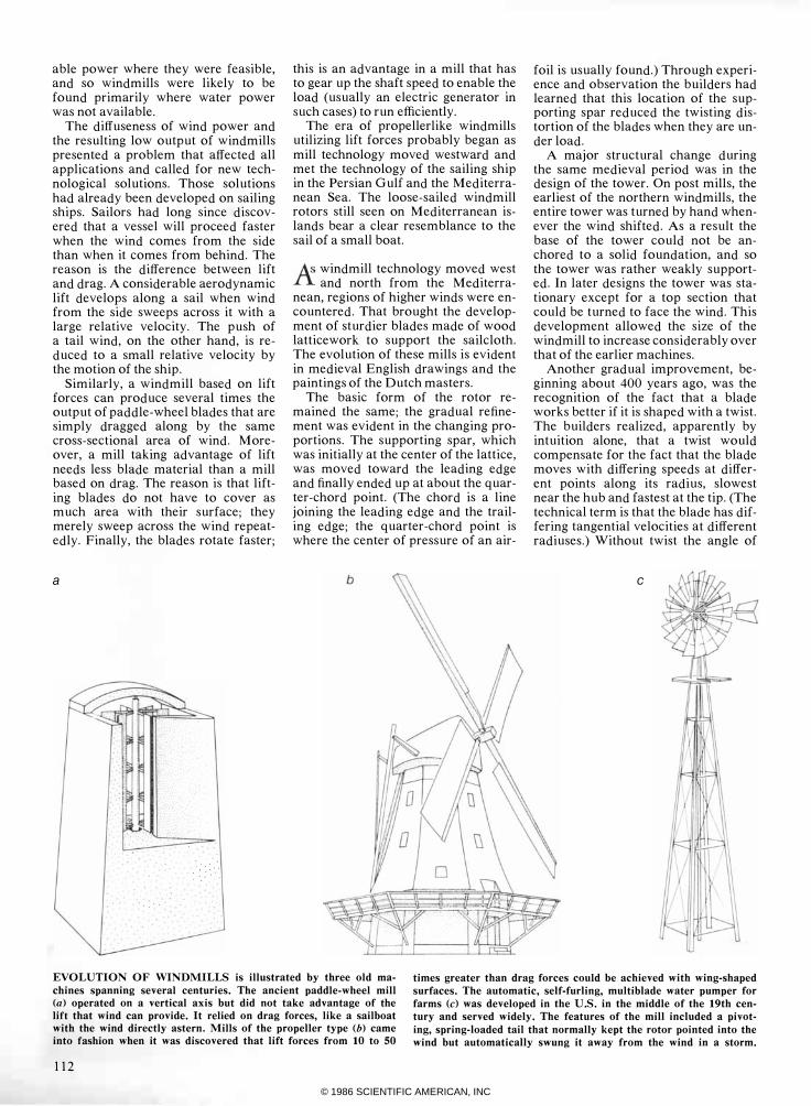
EVOLUTION OF WINDMILLS is illustrated by three old ma
chines spanning several centuries. The ancient paddle-wheel mill (a) operated on a vertical axis but did not take advantage of the lift that wind can provide. It relied on drag forces, like a sailboat with the wind directly astern. Mills of the propeller type (b) came into fashion when it was discovered that lift forces from 10 to SO
times greater than drag forces could be achieved with wing-shaped
surfaces. The automatic, self-furling, multiblade water pumper for
farms (c) was developed in the U.S. in the middle of the 19th century and served widely. The features of the mill included a pivot
ing, spring-loaded tail that normally kept the rotor pointed into the wind but automatically swung it away from the wind in a storm.
112
© 1986 SCIENTIFIC AMERICAN, INC
the blade with respect to the wind is far from ideal and power is lost.
The most sophisticated improvements were effected in the cross-sectional shape of the blades. The addition of a canted leading-edge board in the windmills of Holland in about 1600 provided camber: a curve along the chord. Camber gives the blade more lift and less drag. By the end of the 19th century the leading edge of English windmill blades had developed not only this form of curvature but also an aerodynamically contoured shape with a thick leading edge. The blade had become a true airfoil.
This slow technological evolution took place largely in the absence of any theory or clear understanding of aerodynamics. Trial and error and the accumulation of generations of experience brought about better and more effective configurations. At the same time economic forces led to the development of larger windmills.
Alarge windmill can be more costeffective than a small one be
cause, among other things, it can do more work with the same operating staff. On the other hand, there are practical limits that constrain the maximum size. For the wood-and-canvas mills of the 18th century the upper limit worked out empirically to a rotor diameter of about 30 meters and a mechanical power output of about 40 kilowatts in a very brisk wind.
Other economic factors, in particular the recent emphasis on generating electricity with windmills (more often called wind-turbine generators in this application) rather than grinding grain or pumping water, have continued to push the size of windmills upward. Today's experimental wind turbines have reached about 100 meters in diameter. Even larger mills would be desirable for generating electricity in significant amounts, but increasing size brings structural costs that eventually outpace the economic gains. One limitation at present is that metal-fatigue stresses at the root of the blade, caused by the pull of gravity on the long structure, inhibit further gains in size. Another problem is that as the size increases, the area of wind that is harvested goes up by only the square of the increase, whereas the mass of material needed goes up by the cube. Hence there is clearly a point of diminishing returns and therefore some optimal size, both of which depend on the application intended for the mill.
In conception the windmill has changed little over the centuries. A rotor of the propeller type is supported on a tower; a main shaft is geared up or
down to drive some load, and mechanisms are provided to control the number of revolutions per minute, preventing excessive speed in high winds, and to keep the rotor facing the wind.
Today's windmill designers, under pressure to construct mills that generate electricity efficiently, have had to deal with the same problems that confronted early builders and have moved in the same directions. The most obvi-
ous results are the development of improved airfoil profiles and the changes in materials made possible by metallurgy and polymer science.
Amore subtle development has been the shift from torq ue-maximizing
designs to energy-maximizing designs. The old mills, pumping water and grinding grain, had to start under load, and to do so they req uired a strong
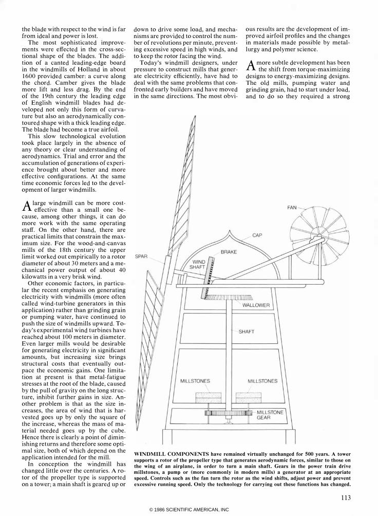
WINDMILL COMPONENTS have remained virtually unchanged for 500 years. A tower
supports a rotor of the propeller type that generates aerodynamic forces, similar to those on
the wing of an airplane, in order to turn a main shaft. Gears in the power train drive millstones, a pump or (more commonly in modern mills) a generator at an appropriate speed. Controls such as the fan turn the rotor as the wind shifts, adjust power and prevent
excessive running speed. Only the technology for carrying out these functions has changed.
113
© 1986 SCIENTIFIC AMERICAN, INC
torque, or tWlstmg force, from the blades in order to turn the grindstones or lift the water. Modern transmission technology in general and electric generation in particular have made it possible to start a wind turbine under minimal load and then to operate it at some optimal speed. Hence the blades no longer must be large enough to enable the mill to start under a heavy load at low wind velocities; instead they can be designed for good fullspeed operation.
A windmill that is optimized for capturing energy will usually have slender, fast-moving blades; the airfoil will exhibit a high lift-to-drag ratio. The theoretically ideal windmill would have a large number of narrow blades. Requirements of structure, on the other hand, call for only a few wide and thicker blades-as many as three
WIND >
F LAT
or as few as one. (A single blade has to be counterbalanced in some way.)
The high speed of the blades is necessary in order to minimize torq ue, which sets up a swirling of air behind the blades that carries energy away instead of converting it to generate power. High speed, however, has its limits: drag ultimately catches up with a fastmoving airfoil, and the tendency of the blade to compress the air through which it moves causes loss of efficiency and excessive noise when the speed of the tip reaches from a third to half the speed of sound.
Economic factors also tend to raise operating speeds. The cost of machinery is closely tied to its weight. High torque necessitates heavier equipment. Power is the prod uct of torque times revolutions per minute. If one can get more speed from a prime mover, one
CAMBERED
can get more output from machinery of a given size. As a result modern generators, including those driven by windmills, all run much faster than those of a few decades ago.
The wind turbine is one of the few prime movers that intrinsically turn slower than the design speed (either 1,200 or 1,800 r.p.m.) of a typical generator. Therefore it requires gearing up, rather than the usual gearing down, between the prime mover and the load. This puts added pressure on the designer to increase the operating speed and reduce the torque. The tip of a modern blade may move at up to 300 miles per hour in a wind of 20 ·m.p.h. In other words, the ratio of the tip speed to the wind speed would be 15. (The relation is usually called the tipspeed ratio.)
Now, the optimal tip-speed ratio is
>
AIRFOIL
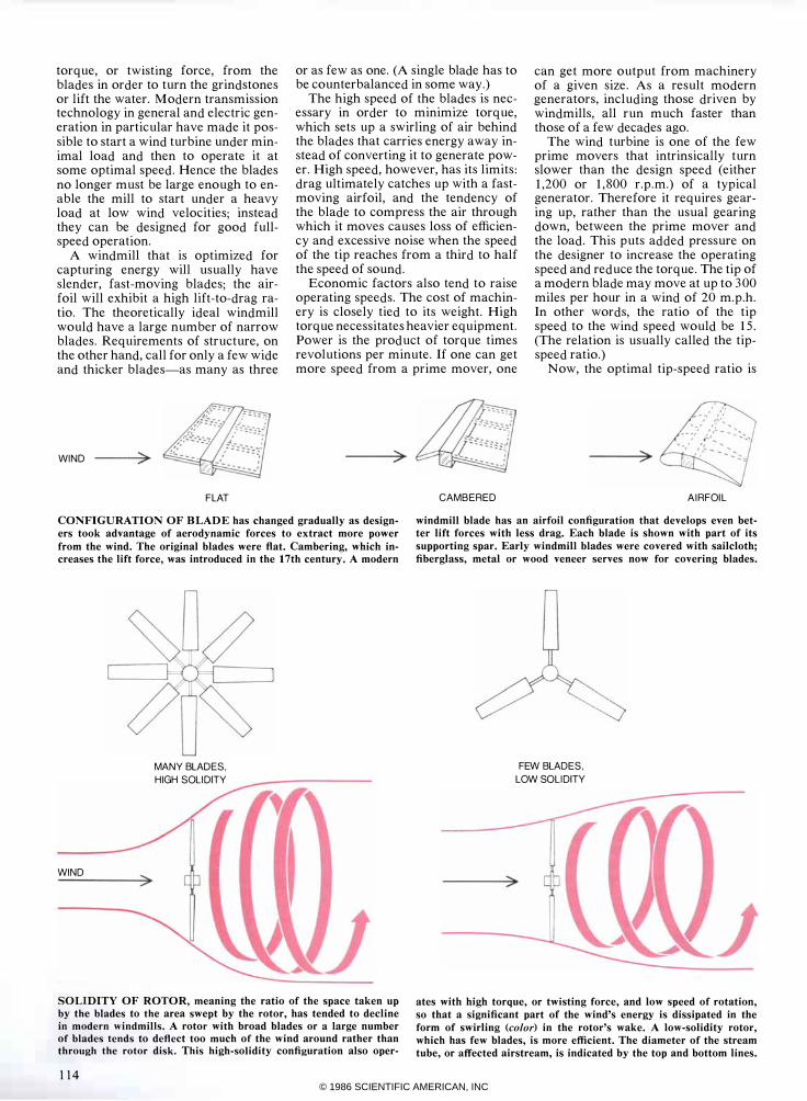
CONFIGURATION OF BLADE has changed gradually as designers took advantage of aerodynamic forces to extract more power
from the wind. The original blades were flat. Cambering, which increases the lift force, was introduced in the 17th century. A modern
windmill blade has an airfoil configuration that develops even better lift forces with less drag. Each blade is shown with part of its
supporting spar. Early windmill blades were covered with sailcloth;
fiberglass, metal or wood veneer serves now for covering blades.
MANY BLADES, HIGH SOLIDITY
WIND
SOLIDITY OF ROTOR, meaning the ratio of the space taken up by the blades to the area swept by the rotor, has tended to decline in modern windmills. A rotor with broad blades or a large number of blades tends to deflect too much of the wind around rather than through the rotor disk. This high-solidity configuration also oper-
114
FEW BLADES, LOW SOLIDITY
>
ates with high torque, or twisting force, and low speed of rotation,
so that a significant part of the wind's energy is dissipated in the
form of swirling (color) in the rotor's wake. A low-solidity rotor, which has few blades, is more efficient. The diameter of the stream tube, or affected airstream, is indicated by the top and bottom lines.
© 1986 SCIENTIFIC AMERICAN, INC
the same for large and small rotors alike, whereas the tip speed is the product of the radius times the r.p.m. For this reason a small wind turbine appears to spin quite fast and a large one to turn at a somewhat leisurely rate, yet they may have the same tangential speed at the tip and the same tip-speed ratio. Small or large, however, a contemporary windmill looks rather spidery and insubstantial compared with an old one.
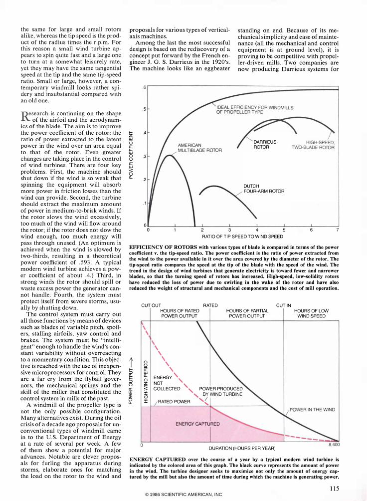
nesearch is continuing on the shape .R of the airfoil and the aerodynamics of the blade. The aim is to improve the power coefficient of the rotor: the ratio of power extracted to the latent power in the wind over an area equal to that of the rotor. Even greater changes are taking place in the control of wind turbines. There are four key problems. First, the machine should shut down if the wind is so weak that spinning the equipment will absorb more power in friction losses than the wind can provide. Second, the turbine should extract the maximum amount of power in medium-to-brisk winds. If the rotor slows the wind excessively, too much of the wind will flow around the rotor; if the rotor does not slow the wind enough, too much energy will pass through unused. (An optimum is achieved when the wind is slowed by two-thirds, resulting in a theoretical power coefficient of .593. A typical modern wind turbine achieves a power coefficient of about .4.) Third, in strong winds the rotor should spill or waste excess power the generator cannot handle. Fourth, the system must protect itself from severe storms, usually by shutting down.
The control system must carry out all those functions by means of devices such as blades of variable pitch, spoilers, stalling airfoils, yaw control and brakes. The system must be "intelligent" enough to handle the wind's constant variability without overreacting to a momentary condition. This objective is reached with the use of inexpensive microprocessors for control. They are a far cry from the flyball governors, the mechanical springs and the skill of the miller that constituted the control system in mills of the past.
A windmill of the propeller type is not the only possible configuration. Many alternatives exist. During the oil crisis of a decade ago proposals for unconventional types of windmill came in to the U.S. Department of Energy at a rate of several per week. A few of them show a potential for major advances. Notable are clever proposals for furling the apparatus during storms, elaborate ones for matching the load on the rotor to the wind and
proposals for various types of verticalaxis machines.
standing on end. Because of its mechanical simplicity and ease of maintenance (all the mechanical and control equipment is at ground level), it is proving to be competitive with propeller-driven mills. Two companies are now producing Darrieus systems for
Among the last the most successful design is based on the rediscovery of a concept put forward by the French engineer J. G. S. Darrieus in the 1920's. The machine looks like an eggbeater
.6
r-----=======:::::::::::::::::::� .5
r- .4 z w l5 u: u. w 0 .3 () a: w
� 0.. .2
. 1
0 0
DARRIEUS ROTOR
DUTCH FOUR·ARM ROTOR
2 3 4 5
RATIO OF TIP SPEED TO WIND SPEED 6 7
EFFICIENCY OF ROTORS with various types of blade is compared in terms of the power
coefficient v. the tip-speed ratio. The power coefficient is the ratio of power extracted from
the wind to the power available in it over the area covered by the diameter of the rotor. The
tip-speed ratio compares the speed at the tip of the blade with the speed of the wind. The
trend in the design of wind turbines that generate electricity is toward fewer and narrower blades, so that the turning speed of rotors has increased. High-speed, low-solidity rotors
have reduced the loss of power due to swirling in the wake of the rotor and have also reduced the weight of structural and mechanical components and the cost of mill operation.
t r=> 0.. r=> o a: w
� 0..
CUT OUT RATED CUT IN
o
HOURS OF RATED HOURS OF PARTIAL HOURS OF LOW POWER OUTPUT POWER OUTPUT WIND SPEED
, ,
\ \
\ \ 8 ,
a: , � ENERGY', Z NOT , � COLLECTED , POWER PRODUCED
i3I� .......
BJ WIND TURBINE RATED POWER " ....
DURATION (HOURS PER YEAR)
ENERGY CAPTURED over the course of a year by a typical modern wind turbine is indicated by the colored area of this graph. The black curve represents the amount of power
in the wind. The turbine designer seeks to maximize not only the amount of energy captured by the mill but also the amount of time during which the machine is generating power.
115 © 1986 SCIENTIFIC AMERICAN, INC
windmill farms in California. Several other vertical-axis mills are now under development in Canada and the u.K.
Since most people in developed countries get electricity from fossil
fuel, nuclear or hydroelectric plants, one wonders how much of a role windmill power can have. At present it serves mainly to supplement conventional systems, but it may come to play a more important role, at least in developing countries.
What is taking place now is a steady growth in the number of wind turbines connected to established power grids. The wind turbines or arrays of turbines are ordinarily distributed widely enough to average out some of the short-term variations in the output of individual machines; the conventional power plant of the grid responds to longer variations. The wind turbines
act as fuel savers for the power company, reducing the load on the fossil plant when the wind blows.
For the longer future one can predict several trends in wind-turbine development. Foremost among them are gradual decreases in cost and increases in mechanical reliability as machines of all sizes move through generations of design development and are produced in greater numbers. Machines in all categories are moving upward in capacity. Residential turbines, typically rated at one kilowatt only a few years ago, are moving toward 10 kilowatts. Machines in windmill farms are advancing from 25 kilowatts toward 200 or more. Research and development machines have grown from a few hundred kilowatts to more than three megawatts.
The most promising developments, however, entail neither greater size nor
new inventions but reduced costs for materials and manufacturing. As wind turbines become larger, a greater percentage of the construction cost is absorbed by the rotor. The development of an effective and inexpensive construction process therefore becomes crucial to the financial success of the machine. Materials being considered, chiefly for blades, include stressedskin metal, fiber-reinforced plastic and weather-resistant wood impregnated with epoxy. In addition, alternative rotor designs of greater structural simplicity are being explored. Among them is a rotor airfoil in which only a few panels are variable and can be adjusted to meet wind conditions and to control the mill; the entire airfoil does not have to be installed on a variablepitch hub.
Technically sophisticated systems for control are increasingly replacing
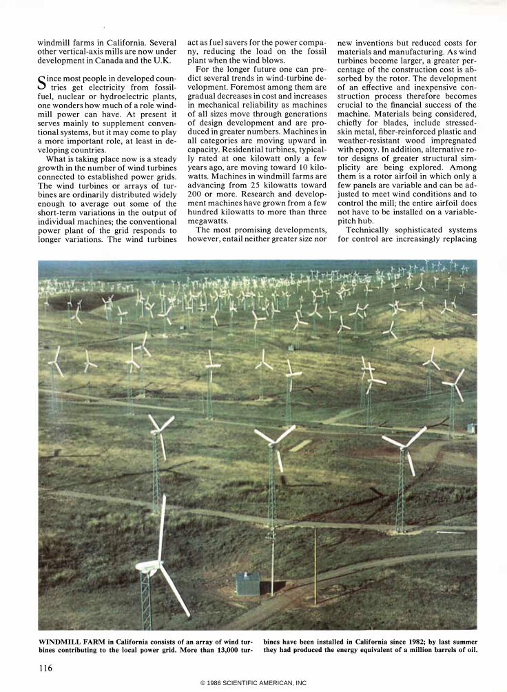
WINDMILL FARM in California consists of an array of wind tur
bines contributing to the local power grid. More than 13,000 tur-
bines have been installed in California since 1982; by last summer they had produced the energy equivalent of a million barrels of oil.
116
© 1986 SCIENTIFIC AMERICAN, INC
Exceeds the minimum daily adult requirement for driving excitement.
Introducing Grand Am SE. Aerodynamic. Monochromatic. With a 3.0 liter multi-port fuel injected V6 and a rally tuned suspension that knows what to
do with a road. Drive one often for fast relief from boredom.
PONTIAC SRAND AM LETS GET IT TOGETHER � BUCKLE UP
WE BUILD EXCITEMENT
© 1986 SCIENTIFIC AMERICAN, INC
"The Bovs Club helped take me
lrom the outlield to the oillield:'
C.J. "Pete" Silas Chairman & Chief Executive Officer, Phillips Petroleum Company
"In the neighborhood where I grew up, there weren' t many places for a kid to spend his time. Except maybe the streets. So it's a good thing there was a Boys Club down the road. It was a place where we learned about something far more impor tant than how to run the bases-how to run our lives.
You see, a Boys Club doesn' t stop at teaching young people good sportsmanship. It teaches them about friendship, good citizenship, leadership. It's nice to know more than 1,200,000 young people at 1,100 Boys Club facilities across the country are getting the same opportunities we had. And more.
Today, they can learn computer skills and get vocational training at a Boys Club. T hey can even get help with college and career planningthe kind of help that can turn a star in the outfield into a star in any field he chooses!
Take it from me, a Boys Club gives a kid a chance to be a leader. And that's a lesson I never forgot!"
118
� BOYSCWB
The Club that beats the streets.
the "simple and cheap" systems that had been the convention. The cost of the control system is becoming small in relation to the gains in performance achieved when the mill operates more efficiently.
The energy needs of the developing countries, now heavily oriented toward oil, will constitute a fertile area for the development of wind power, particularly since all but the larger mills are fairly easy to assemble. Even in the U.S. the current glut of oil cannot be expected to continue indefinite-
ly, and the generation of power by wind is likely to gain gradually on conventional methods. Within just the past three years enough wind turbines have been installed in California to equal 2 percent of the state's installed capacity; they produce 1 percent of its energy. Although the percentages sound small, they represent a power output of more than 600 million kilowatt-hours. Perhaps in a generation or so windmills will again represent a significant source of power, as they did centuries ago.
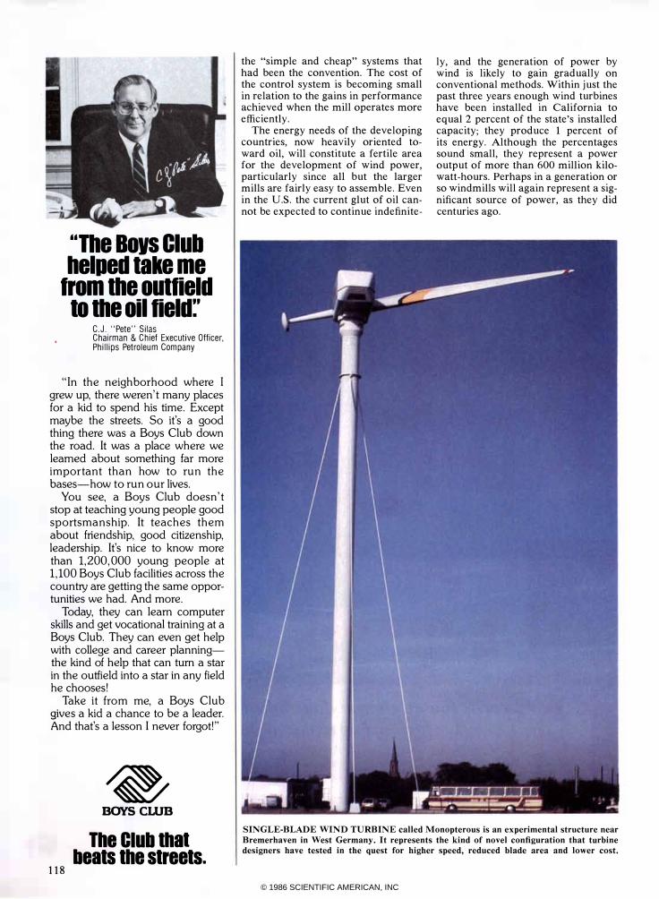
SINGLE-BLADE WIND TURBINE called Monopterous is an experimental structure near
Bremerhaven in West Germany. It represents the kind of novel configuration that turbine designers have tested in the quest for higher speed, reduced blade area and lower cost.
© 1986 SCIENTIFIC AMERICAN, INC

The PCI AT Compatible
Tand ®3000 The difference is power
... and affordability.
T he powerful Tandy 3000 personal computer is the affordable alternative to the IBM ® PC/AT. Here's the power you need to manage your business, either alone, or in a multiuser system.
Designed for high performa�n�c;eiiiiiiiiiiliiiiiiiiiiiiiiiiiiiiiiiiiiiiiiiiiiiii_iiii';'iiiiiiiiJ
Unmatched compatibility The Tandy 3000 uses the advanced
MS-DOS ® 3.1 operating system. And since the Tandy 3000 is compatible with programs designed for the PC/ AT, as well as the PC/XT, it cuts through today's software confusion. Choose from literally thousands of applications, available nationwide.
Power to share T he Tandy 3000 is also designed to
use the forthcoming XENIX® 5.0 multiuser operating system. Two to six people can share the 3000's high speed and storage, using low-cost data display terminals.
T he Tandy 3000 (25-4001, $2599) operates at 8 megahertz-twice the speed of the industry standard. It comes with 512K of main memory and a high-capacity floppy disk drive that can read both 360K and 1.2-megabyte formats, for use with IBM PC diskettes. And the 3000 even comes with a serial/parallel adapter and ten expansion slots.
Or for maximum storage capacity, choose the Tandy 3000 HD (25-4010, $3599) with a built-in, 20-megabyte hard disk drive.
Tandy ... Clearly SuperioeM T he Tandy 3000 has the power to
put you in command. Drop by your local Radio Shack Computer Center and ask for a demonstration today!
Available at over 1200 Radio Shack Computer Centers and at
participating Radio Shack stores and dealers.
ladle Ihael( COMPUTER CENTERS
A DIVISION OF TANDY CORPORATION
PI-------. Send me a Tandy 3000 brOChure .•
I Radio Shack, Dept. 86-A-S73 300 One Tandy Center, Fort Worth, TX 76102
I • Name _________ _
I Company • I Address • C ity _________ _
I State ZIP • I.ih _ ______ .1
Prices apply at Radio Shack Computer Centers and at participating stores and dealers. Monitor and MS-DOS scId separately. IBM/Registered TM International Business Machines Corp. MS-DOS and XENIXJRegistered TM Microsoft Corp.
© 1986 SCIENTIFIC AMERICAN, INC