Embed Size (px)
Citation preview

II I ~ I i...-,
00GENERAL DYNAMICS
o FORT WORTH DIVISION ,.(N
INDUSTRIAL TECHNOLOGY
MODERNIZATION PROGRAMPhase 2
Final Project Report
DTIC -ELFCTE
PROJECT 82
INCREASE EFFICIENCY OF CARD/DEVICETEST AREA BY THE USE OF MODERN
MULTI-PURPOSE TEST EQUIPMENT
REVISION 1 HoneywellMilitary Avionics Division
Dl~tM~IRON STATFEMENT AApproved for public release
Distmution Udiimted I3 48g 9 ; 13 142 ,

uncla~sified
SECURITY CLASSIFICATION oF THIS PAGE
REPORT DOCUMENTATION PAGEIa. REPORT SECURITY CLASSIFICATION lo RESTKICTiVE MARKINGS
unclassified None2a. SECURITY CLASSIFICATION AUTHORITY 3 DISTRIBUTION I AVAILABILITY OF REPORT
2o. DECLASSIFICATION I DOWNGRADING SCHEDULE UnlimitedNone
4. PERFORMING ORGANIZATION REPORT NUMBER(S) S. MONITORING ORGANIZATION REPORT NUMBER(S)
448307BFNone Cited H089-0300
6a. NAME OF PERFORMING ORGANIZATION 6o OFFICE SYMBOL 7a. NAME OF MONITORING ORGANIZATION(If applicable)
Honeywell, MAVD General Dynamics/Ft. Worth6c. ADDRESS (City, State, and ZIP Code) 7b. ADDRESS (City, State, and ZIP Code)
St. Louis Park, MN 55416 Fort Worth, TX 76101Ba. NAME OF FUNDING /SPONSORING 8b. OFFICE SYMBOL 9. PROCUREMENT INSTRUMENT IDENTIFICATION NUMBER
ORGANIZATION j (If applicable) Contract# F33657-82-C-2034F-16 SPO j ASD P.O.# 1005262
8c. ADDRESS (City, State, and ZIP Code) 10. SOURCE OF FUNDING NUMBERS
PROGRAM IPROJECT _ TAIWRKUIELEMENT NO. NO. No. ACCESSION NO.
Dayton, OH 45433
11. TITLE (Include Security Classification)Phase 2 Final Project Report #82 - Increase Efficiency of Card/Device Test Area by theuse of Modern Multi-Purpose Test Equipment, Revision 1
12. PERSONAL AUTHOR(S)Robert Knox
13a..TYPEC: REPORT13b. TIME COVERED 14. DATE OF REPORT (Year, Month, Day) 15. PAG E COUNTiidl"OTFROM 1986 T01988 88,03,01 1U0
16. SUPPLEMENTARY NOTATION
CDRL ITM-004
17. COSATI CODES ,4 B. SUBJECT TERMS (Continue on reverse if necessary and identify by block number)FIELD GROUP SUB-GROUP Multi-Purpose Auto Test Equipment-_
3 nI
19. ABSTRACT (Continue on reverse if necessary and identify by blok number)Multipurpose test equipment in the printed cqrcuit card and completed device test areaswill be used for functional acceptance test, toubleshooting, and burn-in operations.The use of this more modern equipment will resu in increased productivity and testyields by a reduction in test execution and fault I olation time and by providing enhanceddata collection and analysis resources. Id,s,
20. DISTRIBUTION/AVAILABILITY OF ABSTRACT 21. ABSTRACT SECURITY CLASSIFICATIONC'UNCLASIFIED/UNLIMITED C SAME AS RPT. 0 DTIC USERS unclassified
22a. NAME OF RESPONSIBLE INDIVIDUAL 22b. TELEPHONE (include Area Code) 22c. OFFICE SYMBOL
Captain Curtis Britt 513-258-4263 , YPTMDO FORM 1473, 84 MAR 83 APR edition may be used until exhausted, SECURITY CLASSIFICATION OF THIS PAGE
All other editions are obsolete, unclassified

Honeywell
MARCH 1, 1988GENERAL DYNAMICS
FORT WORTH DIVISION
INDUSTRIAL TECHNOLOGYMODERNIZATION PROGRAM
PROJECT 82 REVISION 1
PHASE 2 FINAL PROJECT REPORTINCREASE EFFICIENCY OF CARD/DEVICE
TEST AREA BY THE USE OF MODERNMULTI-PURPOSE TEST EQUIPMENT
/
AVIONICS SYSTEMS GROUPMIUTARY AVIONICS DIVISIONIMg ZARTHMAN AVE
ST. LOUIS PARK. MN 55416

ii

PROJECT 82
TABLE OF CONTENTS
SCLE AE
1 INTRODUCTION 1
2 PROJECT PURPOSE/OVERVIEW 3
3 TECHNICAL APPROACH 6
4 "AS-IS" PROCESS 18
5 *TO-BE" PROCESS 33
6 PROJECT ASSUMPTIONS 42
7 GROUP TECHNOLOGY CODING SYSTEM ANALYSIS 43
8 PRELIMINARY/FINAL DESIGN AND FINDINGS 44
9 SYSTEM/EQUIPMENT/MACHINING SPECIFICATIONS 53
10 TOOLING 64
11 VENDOR/INDUSTRY ANALYSIS/FINDINGS 65
12 EQUIPMENT/MACHINERY ALTERNATIVES 89
13 MIS REQUIREMENTS/IMPROVEMENTS 90
14 COST BENEFIT ANALYSIS AND PROCEDURE 92
15 IMPLEMENTATION PLAN 98
16 PROBLEMS ENCOUNTERED AND HOW RESOLVED 102
17 AREA FOR FUTURE CONCERNS/DEVELOPMENT 104
AcCesIi F-or
UU C l/ [
6
ByOastrib:.io,, I
ii i D is t - , .
L--
PROJECT 82
LIST OF ILLUSTRATIONS
GRME PAGE
3.1-1 PROJECT APPROACH AND METHODOLOGY 7
3.1-2 TYPICAL ITERATIVE PROCESS 9
3.1.1-1 MULTI-DIMENSIONAL SPACE EXAMPLE 10
3.2-1 EQUIPMENT SELECTION APPROACH 12
3.2-2 TOOLING AND EQUIPMENT EVALUATION MATRIX 16
4.0-1 "AS-IS" PRODUCTION PROCESS (FM&TS) 19
4.5.1.2-1 ATE CENTRAL: "AS-IS' 25
4.5.1.3-1 FM & TS CARD TEST ADAPTERS • 26
5.1-1 "TO-BE" PRODUCTION PROCESS (FM&TS) 34
5.3.1-1 SIGMASERIES TEST MODULE INTERFACES 37
5.3.3-1 OVEN MONITOR NETWORK 39
5.3.3-2 "TO-BE" FM & TS OVEN ISOLATION STRUCTURE 40
8.3.2-1 ATE MANUFACTURE'S SURVEY 47
8.5-1 OVEN MONITOR NETWORK 51
8.5-2 "TO-BE" FM & TS OVEN ISOLATION STRUCTURE 52
11.1.1-1 ATE MANUFACTURE'S SURVEY 66
11.1.2-1 CURRENT ATE REQUIREMENTS MATRIX 74
11.1.3.1-1 SIGMASERIES TEST MODULE INTERFACES 79
11.1.3.3-1 SIGMASERIES NETWORK INTEGRATION 82
14.0-1 COST BENEFIT ANALYSIS METHODOLOGY 93
14.2-1 PROJECT 82 EXPENDITURE SCHEDULE 96
14.3-1 PROJECT 82 CASH FLOWS 97
15.1-1 PROJECT 82 - IMPLEMENTATION PLAN 99
iv

PROJECT 82
INCREASE EFFICIENCY OF CARD/DEVICETEST AREA BY THE USE OF MODERNMULTI-PURPOSE TEST EQUIPMENT
SECTION 1
INTRODUCTION
The Flight Management and Targeting Systems (FM & TS) ProductionDepartment is chartered to manage and produce a variety of fixed and rotarywing aircraft electronics in support of the Flight Systems Operation (FSO).
The mission of FM & TS Production is to generate revenue and profit byexecuting production contracts in support of FSO profit and ROI objectives. FM& TS products are typically low volume, high technology devices built underspecific customer contracts.
The Flight Management Area produces flight control systems forfixed and rotary-wing military aircraft for various customers. While the functionof each of the systems is relatively similar in nature, each system is unique inthe functions controlled on .the aircraft, the quantity of devices (black boxes)which make up the system, as well as the specific customer build and testrequirements.
As a rule, the component devices for a system are required to beinterchangeable from one system to another and are therefore tested andshipped to the customer as individual devices. Most of these devices consist ofa chassis into which printed circuit cards and other sub-assemblies are insertedto form a functional black box. The various devices contain from 10 to 25printed circuit cards and are produced in relatively low quantities. Otherdevices which are part of the systems may contain fewer than 3 printed circuit orsimilar type devices and are also produced in low quantities.
The Targeting Systems Area produces an advanced helmet mountedsighting and display system. This system consists of several componentdevices which require unique skills to produce. Two of the "black boxes" aresimilar in nature to those described above for the Flight Management Area andrequire similar assembly and test techniques. However, the remainingcomponent devices are unique to FM & TS. The display system utilizes aminiature cathode ray tube mounted on the pilot's helmet and requires preciseassembly and test of optical and electronic devices. The sighting systemconsists of several components precisely mounted on the helmet and other

sensor units which are mounted in the aircraft cockpit. These units also requireunique assembly and test skills with very tight controls. As with the FlightManagement Area, these systems are produced in relatively low quantities.
Project 82 was initiated to provide increased quality and efficiency by theuse of modem multi-purpose test equipment for printed wiring cards anddevices tested within FM & TS. These improvements include:
New, highly automated assembiy test station
Continuation of the Fluke 3050B testing
Comprehensive oven monitoring network
These additional improvements implemented under Project 82 willprovide FM & TS with a significant increase in the efficiency of theirmanufacturing, help to reduce their overall manufacturing costs, and provide ahigher quality product.
2

SECTION 2
PROJECT PURPOSE/OVERVIEW
The following section presents an overview of ITM Project 82. Anoverview of the FM & TS Production department and it's primary objectives isalso presented along with a brief description of the Tech Mod efforts atHoneywell.
2.1 FM & TS Ovevlew
Flight Management and Targeting Systems (FM & TS) Production ischartered to manage and produce a variety of fixed and rotary wing aircraftelectronics in support of the Flight Systems Operation (FSO).
The mission of FM & TS Production is to generate revenue and profit byexecuting production contracts in support of FSO profit and ROI objectives. FM& TS products are typically low volume, high technology devices built underspecific customer contracts. The FM & TS Production organization directlyprovides Production Engineering, Production Control, and operatingcapabilities to manage and execute production programs, support engineeringprograms, and provide specialized services to other product areas. Quality,Logistics, Procurement and Manufacturing Technical Services support isprovided to FM & TS Production by Honeywell's Military Avionics Division(MAvD) central organizations.
The priority objective within FM & TS Production is to produce qualityproducts within cost goals. Additional objectives include flexibility anddependability with the emphasis differing slightly in each of the focusedfactories.
2.2 FM & TS and Tech Mod
The USAF Tech Mod program was instituted to provide strategicplanning and develop facility modernization projects that reduce manufacturingcosts, improve product quality and reliability, and reduce manufacturingthroughput time. In addition, the Tech Mod program has been chartered withassuring the capability for a rapid increase in production in the event of nationalemergency.
Under the guidance of the Tech Mod program, Honeywell has definedseveral areas for improving production in the Flight Management and TargetingProduction facility in St. Louis Park, Minnesota. ITM Project 82 has beeninitiated with the purpose of upgrading the FM & TS Card/Device testing areasand is described in the following section.
3

2.3 Project 82 Strategic Goals and Objectives
FM & TS Production has defined several major objectives that are beingincorporated in their future business planning. These objectives includeincreasing the flexibility of their operations and improving product quality, whilemaintaining a high degree of cost control.
Cost control is the overriding objective of FM & TS Production planning.This control must be maintained for both existing program production as well asfor new programs. The cost control efforts underway in FM & TS Production arewide-ranging and are being applied at every level of the organization.Examples of this can be seen in the current implementation of the HMS/BOSMRPII system in St. Louis Park as well as the implementation of the FactoryData Collection System. In addition to controlling costs, the following objectiveshave been defined as critical to FM & TS's future production operations:
Increase flexibility of operations. FM & TS willmanufacture between six and ten products at anyparticular time and with the introduction of newprograms which introduce both process and productchanges, the current operations must remain flexiblein adapting to these changes while still maintainingthe capability of supporting existing programs.
Increase product quality. By achieving 100%conformance with customer requirements, Honeywellwill be viewed as the leading supplier of MilitaryAvionics products. While this is of important strategicvalue from a marketing perspective, it can also havea direct effect on lowering the manufacturing costs insuch areas as reducing rework and scrap.
Reducing production lead times. Customerrequirements dictate shorter production lead timesand these will be accomplished through developingmore streamlined process, material, and productionflows. Improvements in information processing (suchas HMS and FDC) will also aid in reducingproduction lead times.
ITM Project 82 has been defined by the Honeywell Tech Mod ProjectTeam for implementation in Flight Management and Targeting SystemsProduction. This project, as defined by the Tech Mod Project Team, isdescribed below.
ITM Project 82 addresses the modernization of multi-purpose testequipment in the printed circuit card and device test areas within the FlightManagement and Targeting Systems (FM & TS) department. The newequipment will be used for functional acceptance test, troubleshooting, and
4

bum-in operations on both new and existing programs/products. The benefitsassociated with the implementation of ITM Project 82 include:
* Faster, more comprehensive card and device programdevelopment
0 Lower cost ATE hardware configuration for equivalent orbetter performance
* Improved diagnostic potential on faulty Units Under Test(UUT)
* Increased availability of digital circuit card assembly testequipment
* Upgrading of environmental chambers with micro-processor-based controllers
0 Improved monitoring and control of environmentalchambers via PC-based network
This project represents a significant part of the overall Tech Mod programcurrently being administered in Honeywell's Military Avionics Division.
5

SEOTION 3
TECHNICAL APPROACH
The following subsections describe tne general approach andmethodology adopted by the Project 82 team for this project. The overallapproach and methodology for performing an in-depth analysis of the FM & TScard and device area testing and bum-in operations are described as well asthe methods employed in developing a structured design for more advancedoperations. In addition, the evaluation methods used to establish technicalrequirements which define the areas for improvement within the card anddevice operations are presented.
The approach developed for selecting equipment is also described. Thisincludes the methodology used to develop requirements for equipment, theselection criteria, and the high level evaluation matrices.
3.1 Overview of Project Approach and Methodology
This section describes the overall approach and methodology employedin the in-depth analysis of the FM & TS card and device testing and burn-inoperations and presents the methods used by the project team in developing anautomated testing and bum-in approach for more advanced operations with theintroduction of newer programs. In addition, this section presents the evaluationmethods used to establish technical requirements which define the areas forimprovement within the card and device testing and bum-in operations.
The project team has developed an overall approach for performing ITMProject 82 which is summarized in Figure 3.1-1. During the initial phase of theproject, this approach required the collection of a great deal of information,including:
* Project 82 Statement of Work* Tech Mod Program Goals* FM & TS Business* FM & TS Products* Personnel Interviews* Facility Tours* Card and Device Area Existing Test Equipment• Card and Device Area Existing Bum-In Equipment* Card and Device Area Existing Control and Monitoring Systems
This information was assimilated by the project team and presented in aseries of meetings designed to assure that the team fully understood the variousfacets of the FM & TS card and device testing and burn-in operations. Theanalysis resulting from this exercise, along with the technologicalunderstanding of similar operations to that of FM & TS and the new systems,
6

Personnel Profect 82 G3eneral ExistinglnaefveWs Stmnent Business Equipment
of Wrk Information Information
Fac~ly Touirs TehMod PoutSYSem
Current
OoperationsPrinciples AnDescitionAme
Enirnentsnt
ada
Information o
Flow
CIM ~ ~ ~ ~ ~ Cs Benem uretNo ysesIw~rt Aalysis alysmes
Fiurr.incrjetiprochadletoolg
7miinn o prtos

operations, equipment, strategy, and tactics developed by the project team,were then utilized in developing the future operations design as well as theequipment specifications to provide a modern multi-purpose test and burn-inoperation.
The final phase in this process is the development of a migration planwhich outlines the implementation steps required to achieve the final plan and acost benefit analysis which defines the benefits in respect to the necessaryinvestment and the time required to realize a return on Honeywell's investment.
In utilizing the approach described above, the project team has foundthat an iterative process methodology would yield the best results in the creativeprocess of designing systems and operations similar to the FM & TS operations.This methodology is particularly applicable in the type of environment, both froma physical perspective as well as a business and management perspective, thatexists for the. Honeywell project team.
In the early stages of the project, the iterative process consisted of thepresentation of information collected and assimilated by the project team in aconcise format. After an agreement as to the adequacy of the presentation wasreached at this level, the process moved further into more detailed levels. Thisis the basis of the iterative process. Further iterations addressed the first initialconceptual levels of design and requirements development and, as more detailwas agreed upon, more precise elements were put into place.
The feedback generated as a result of each of these presentations andthe incorporation of this information into the final report assures that the resultsof the overall design process are compatible with the desires and ideasexpressed by users and management organization. The iterative designprocess is illustrated in a conceptual manner in Figure 3.1-2.
3.1.1 Operations Analysis
The goal of a comprehensive operations analysis is to first describe thecurrent operations of Honeywell's FM & TS card and device testing and bum-inareas. Based upon this description, specific areas and operations are defined(in accordance with the statement of work) for further analysis as theysignificantly impact the direct or indirect costs of FM & TS production. Thisanalysis then provides the foundation upon which the operations of the future isdesigned.
The absolute and definitive areas which are identified as cost drivers inthe card and device operations lie in a multi-dimensional space with complexinterrelated dimensions that are difficult to delineate. The primary task in theanalysis phase is to determine the methods and approach required to defineand analyze an issue which is extremely complex. As shown in Figure 3.1.1-1,this multi-dimensional space is characterized by the hierarchical levels existingwithin the FM & TS organization and the specific objectives of ITM Project 82.
8

Colcto and / Expertise, Ideas,Operations Requirements andnWants
ProductHoneywell Team
Oter Sources
~Public Dolai'
* Information Assimilation Information* Concepts Creation Analysis" Deductive Results
_ I Technology
Iterative Results Presentation -Analysis Comments and RemarksProcess
ResultsApproved
Figure 3.1-2 Typical Iterative Process
9

a
.3
jjI~.iii liiiILLIL
s.N)oefqo ~eb~
I11II;u.
0.~
iiII
FIgure 3.1.1-1 MultI-DImensIonal Space Example
10

By specifying the general objectives to be achieved, it is possible toreduce the complexity of these interrelated dimensions and to define objectivesfor each of the levels of operations and analyze improvements to be made ateach level. Once these objectives have been defined at a specific level, it isthen necessary to establish the significant variables and criteria that willinfluence the analysis and recommendations made for each of these levels.
3.1.2 Structured Design Approach
The structured design approach employed by the project team is directlydependent upon a detailed analysis of the specific FM & TS operations for thecard and device areas. The previous section described the methodology usedto approach a large, complex, interrelated structure and "break down" thatstructure into discrete entities (i.e., specific equipment and resources). Once theoperations have been analyzed at a discrete enough level to understand theprocesses and unique characteristics at each level, it is possible to rebuild eachof the levels progressively to transform the operations into a more advancedmanufacturing structure.
Large scale matrices were developed which correlated the Honeywellpart number (of each assembly, sub-assembly, and component part of allproducts produced by FM & TS) with the operations (i.e., test, bum-in, etc.) andthe standard hours required to perform these operations. These correlationmatrices provided important information for defining the equipment required foreach specific program.
A number of other factors (which are prmarily concerned with the overallarea layout, material handling requirements for these areas, and productionvolume) have influenced the general equipment requirements.
Once the equipment requirements for testing and bum-in are defined, it isnecessary to present specific technical solutions that can be implemented in themost efficient and effective manner. The following section describes the projectteam's approach to evaluating the technical requirements that result from theanalysis and design process and the selection tools that have been developedfor the specific types of equipment that will be a part of the overall FM & TSsolution
3.2 Equipment Selection Approach
The selection of equipment employed for ITM Project 82 was definedusing a general approach and then a more refined methodology based on thisapproach was used for each specific piece of equipment. This generalapproach is described below and presented pictorially in Figure 3.2-1.
11

Define All Possible Equipment Required
(Functional Description)
Establish Selection Cdrteial
Value Criteria(Per Specific Piece of Equipment)
Research Vendorsj
Establish Selection Matrix
o-Evaluate Equipment I
Iterativ Vendor Selection for Bidding Process
Process(Minimum 3)
Define Cost Trade-Offs(ROI, Critical to Production)
Select Equipment
Figure 3.2-1 Equipment Selection Approach
12

The first step in the selection of equipment is to define all of the possibleequipment required to perform the process necessary for production. This wasapproached from several different vantage points:
Current equipment survey. All equipment currently used in aproduction area was reviewed for functionality, age, ease of repairand availability of spares, as well as several other factors specificto the unique piece of equipment.
Production processes. The processes called out by the productionlayouts were reviewed to determine if current equipment couldadequately perform those processes and what new availableequipment could be used to perform production processes.
Technology overview. Recent technological advances inproduction equipment were reviewed to ensure that during theequipment evaluation process that all applicable or substitutabletechnologies were understood in relation to the production areaand the processes performed there.
Following the establishment of production equipment requirements,selection criteria were established to evaluate each individual piece ofequipment. A general overview of these criteria includes:
Physical Crter
Conformance to Requirements - Equipment meets (or exceeds) capabilitiesrequired, such as capacity, frequency, accuracy, MTBF.
Ease of Use - Required level of technical expertise/training necessary toeffectively operate equipment.
Technology Level - Employment of state-of-the-art features or innovativeapplication of technology that enables user to more effectively perform intendedtask.
Multiple Users - Ability to support more than one user simultaneously (eitheroperating or programming).
Network Capability - Ability of equipment to be networked to other similar unitsor to centralized data files or controller.
Defect Detection and Reporting Capabilities - Effectiveness of reporting ofdefects on unit under test so as to permit repair in shortest possible time.
Support
Serviceability - Ease of maintaining equipment plus vendor's supportcapabilities/response level.
13

Technical Support Requirements - Level of technical expertise/training requiredto effectively support (program, maintain, etc.) equipment.
Cost of Programming - Relative effort required to develop operational programs
for equipment.
Physical Chmctrtlcs
Portability/Moveability - Effect on critical adjustments/required participation ofvendor.
Ease of Installation - Effects on installation due to physical size,mounting/isolation requirements, vendor or customer team required.
Ease of Upgrading/Modifications - Convenience of installing additionalcapabilities/features/options as well as field changes (both hardware andsoftware).
Physical Interfacing - Relative level of ease in providing interface to unit undertest (UUT) or other equipment being operated on.
Cooling Requirements - Special HVAC (Heating, Ventilation, Air Conditioning)requirements necessary for equipment due to operating temperature and range.
Environmental Impact - Provisions required due to equipment-generated heat,noise, vibration, etc.
Power Requirements - Exceptional or unusual power requirements equipmentas compared to similar types of equipment being considered.
Special Environmental Requirements - Special environment requirements such
as "clean" room, dark room, isolation mounting, etc.
Vendor Evaluation
Delivery - Availability of equipment in accordance to needs.
Vendor Reliability - Supplier's record in delivering and supporting equipment(evaluate by questioning other users).
Equipment Cost - Evaluated in relation to other similar pieces of equipmentunder evaluation for a given use (i.e., relative cost of unit).
It is then necessary (for each piece of equipment required) to "weigh" orvalue the criteria, selecting the most important criteria for a specific piece ofequipment. The weighted factors associated with that equipment are then usedto perform an initial vendor review.
14

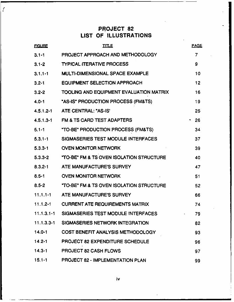
The weighted criteria is ranked for level of importance or applicability tothe decision making process and listed on one side of an equipment selectionmatrix (shown in Figure 3.2-2). This matrix is used to evaluate the vendor'sproduct applicability and to screen out the vendor whose equipment is notsuitably matched to the requirements.
The vendors whose products meet the initial requirements are sentspecifications (RFQ's) to respond to. Once the initial cost of the equipment isestablished, the selection process then becomes an iterative process ofdefining the cost trade-offs involved, determining if the ROI is sufficient andreviewing the criticality of the new equipment and its effect on production. Thefinal step in this process is the purchase of the equipment and the initiation ofthe program's implementation.
15
EquipmentSelection Vendor A Vendor B Vendor NCriteria
Conformance toRequirements
Ease of Use
Technology Level
Multiple Users
Network Capability
Defect Detectionand ReportingCapabilities
Serviceability
Technical SupportRequirements
Cost of Programming
Portabiity/Movability
Figure 3.2-2 Tooling and Equipment Evaluation Matrix
16

EquipmentSelection Vendor A Vendor B Vendor NCriteria
Ease of Installation
Ease of Upgrading/Modifications
Physical Interfacing
CoolingRequirements
EnvironmentalImpact
Power Requirements(Normal vs.Exceptional)
SpecialEnvironmentalRequirements
Delivery
Vendor Reliability
Equipment Cost
Figure 3.2-2 Tooling and Equipment Evaluation Matrix (cont.)
17

SECTION 4
"AS-IS" PROCESS
The following section presents a description of the "As-Ism condition of theFM & TS operations. This includes a brief description of the type of productcurrently in production and the organizational structure of Flight Managementand Targeting Systems as well as the personnel involved in FM & TSProduction. In addition, the test and bum-in equipment used in the card anddevice area is described.
An overview of the current "As-Is" process required to produce FM & TSproducts is depicted in Figure 4.0-1.
4.1 FM & TS Production Overview
FM & TS Production manufactures products for five major programs aswell as producing spares for these and other older programs.
4.2 FM & TS Program Profiles
Flight Management and Targeting Systems Production assembles andtests high technology military flight control and targeting systems built underspecific customer contracts. Therefore, while there may be several productswithin a particular program, each program must be managed and controlled tocomply with a specific customer's requirements. The systems that are builtunder each of the program's currently under contract to FM & TS are typicallymade up of a variety of components, including:
* Computers• Control Panels• Sensors• Control Sticks* Electronics Units
The orders for any one of these program's products may be made for completesystems, modification packages, or spares.
In addition to the various programs which are in current production, asignificant amount of FM & TS Production's business is made up of militaryspares and/or repairs on older programs.
18

a -20 2
a 4
01 z
z -2
244ih 0~ --
I-
owl
Le
Figue 40-1"As-s" rodctin Prces (F&TS
19S
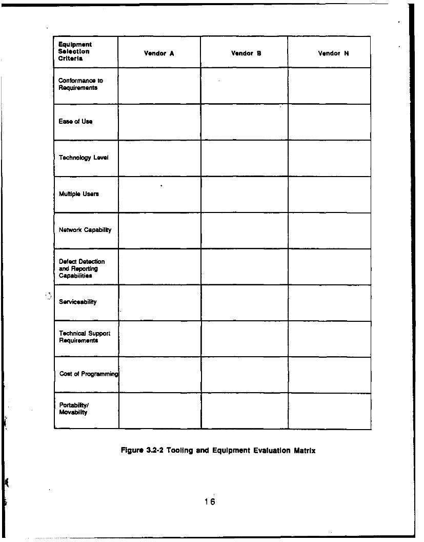
4.3 FM & TS Organizational Structure
The Flight Management and Targeting Systems (FM & TS) Productionoperations play a central role in Honeywell's Military Avionics Division's (MAvD)Flight Systems Operations (FSO) organization. The organizational structure ofFSO is divided into several major functional areas, including:
* Production* Program(s) Management* Engineering• Product Assurance* Procurement
Each of the areas within FSO are structured as independent, function-oriented organizations that report to other areas on a "dotted line" basis. Withinthe Production area of FSO, the organizational structure is primarily high-level-product oriented. These high-level-product related areas are divided into:
* Flight Management and Targeting Systems Production* Missile System Microwave Production* Printed Wiring Assembly* Aircraft System Microwave Production• Advanced Systems* Central Production Services
While the divisional distinctions within FSO are primarily high-level-product oriented, the products produced by each group are also significantlydistinct from a manufacturing process perspective.
The Flight Management and Targeting Systems Production operationsare functionally divided into several areas, including:
* Production Engineering* Production Control• Assembly
These areas, which are separated organizationally, are interrelated to worktogether in an overall manner to support each of the products manufactured bythe FM & TS operation. In that respect, each of these divisions provide inputand receive assistance from the other two areas.
While the organizational division at this level is functional, the inter-division communication is defined by specific product programs. While thisrequires comprehensive management by each of the supervisors, it allows fordirect information exchange where it is most beneficial (i.e., for each of the FM &TS programs).
20

4.4 Test and Bum-n Operations Overview
The primary activities in the card and device production area are the testand calibration of circuit card assemblies (CCA) and the test, calibration, andenvironmental exercise of devices (black boxes). The activities of thisorganization are augmented by a special assembly group known as the FinalAssembly Support Team (FAST) which includes modification, engineeringorder (E.O.) incorporation, and rework capabilities.
Within the FM & TS areas, the processing of electronic assembliesbegins with card test and calibration. CCA's are received from an assemblyarea located at the St. Louis Park facility which is dedicated to that function.The cards are first tested and any operational faults are detected and repaired.If a card requires the addition of a component to calibrate a specific circuit, thevalue is determined and the component is installed.
Once the card is fully functional, it is transported to the Paint and Coatingarea for a conformal coat. Subsequent to the coating operation, the card isstocked in the area for later inclusion in a device chassis.
If a specific CCA is intended to be shipped directly to the customer as aspare, it is retested and, if fully functional, presented to the inspectiondepartment for.final approval prior to shipment.
As orders for devices are released, area personnel select the correctcard complement from the stocking cabinets and install them in the chassis fortesting.
Each device is run through a programmed checkout or pre-ATP(Acceptance Testing Procedure) on ATE equipment to determine if it exhibitsthe correct functions in preparation for an environmental test (the exception tothis is the major components of the Targeting Systems programs which arechecked out in system configuration lashups instead of individual ATEadapters). An Acceptance Test Procedure has been developed which eachdevice must correctly pass to be a shippable unit.
Once the device is working properly, it is installed in an environmentalchamber that subjects each unit to temperature cycling over a program specificperiod. Depending on the specific program, each unit will be subjected to eithersinusoidal or random vibration during this burn-in period. Units requiringrandom vibration are transported to the Development & Evaluation (D & E) Labsfor testing since the capability does not exist within the FM & TS Productionarea.
Device performance is monitored periodically during environmentaltesting and any malfunction requires that the device be removed from thechamber and be repaired.
21

Once the device satisfactorily passes the environmental test, it is runthrough a final ATP and accepted by quality and/or customer representatives.Final labeling and packaging completes the pre-ship procedures.
4.5 Test Equipment
The following section describes the test equipment currently used inHoneywell's FM & TS Production area. This equipment includes:
* ATE Consoles
* Fluke Circuit Board Tester
0 Manual Test Consoles
* Environmental Chambers
* General Purpose Test Equipment
• Adapters for Cards, Devices, and Environmental Bum-In
A detailed description of each of the major equipment types is presented
in the following subsections.
4.5.1 Honeywell Automatic Test Equipment
The Honeywell ATE unit is a programmable, computer controlled testerdesigned to automatically test electronic modules of varying complexity forfunctional compliance with specifications for voltage type, frequency, amplitude,time duration, logic state, etc. Under program control, it is capable of providingthe necessary stimulus to a Unit Under Test (UUT) so as to properly exercisespecific operational functions which may be automatically measured.
4.5.1.1 Hardware
The Honeywell ATE has been in use for production testing on FM & TSassemblies for over eighteen years. The ATE is a computer-controlled testerutilizing a stored program to exercise both modules (printed circuit assemblies)and devices (card cages or "black boxes"). The computer acts as the controlpoint of the operations of various instruments in the system that provide stimulusto and measure response from a unit undergoing test.
The ATE units in use in the FM & TS area are primarily configured asanalog testers. The Honeywell ATE is a multi-bay cabinet consisting of rack-mounted measurement instruments and stimulus devices (e.g., power supplies,signal generators, waveform generators, etc.) controlled through an instrument
22

addressing scheme with stimulus and measurement values transmitted backand forth to the H-316 controller via binary or BCD coding. The instrumentstimulus output and measurement input points are wired to a main receiverchassis which provides interconnection to units to be tested via an interfacepatch panel as directed by the respective test program.
Typically, a unit under test is interfaced to the ATE via an adapter whichcontains the necessary interconnection hardware to both mate with the unitunder test and the receiver (or main interconnection panel) of the ATE unit. Anadditional function of the adapter is to provide the signal terminations androutings (as well as power connections) which are required by the unit undertest.
Typically, each of the ATE units has the following programmableinstruments:
* DC Signal Sources
* AC Signal Sources
0 Function Generator
* Pulse Generator
* Decade Resistance Panel
* DC Power Supplies
* Digital Voltmeter
Threshold Detector
Time and Frequency Digitizer
Time Delay Generator
AC/DC Converter
Additionally, power supplies are provided to energize units undergoingtest. These include:
* 28 VDC
115 VAC, 400 Hz, 3 0
26 VAC, 400 Hz
23
4.5.1.2 ATE Central
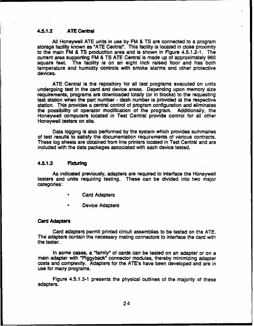
All Honeywell ATE units in use by FM & TS are connected to a programstorage facility known as "ATE Central". This facility is located in close proximityto the main FM & TS production area and is shown in Figure 4.5.1.2-1. Thecurrent area supporting FM & TS ATE Central is made up of approximately 960square feet. The facility is on an eight inch raised floor and has bothtemperature and humidity controls with smoke alarms and other protectivedevices.
ATE Central is the repository for all test programs executed on unitsundergoing test in the card and device areas. Depending upon memory sizerequirements, programs are downloaded totally (or in blocks) to the requestingtest station when the part number - dash number is provided at the respectivestation. This provides a central control of program configuration and eliminatesthe possibility of operator modification of the program. Additionally, theHoneywell computers located in Test Central provide control for all otherHoneywell testers on site.
Data logging is also performed by the system which provides summariesof test results to satisfy the documentation requirements of various contracts.These log sheets are obtained from line printers located in Test Central and areincluded with the data packages associated with each device tested.
4.5.1.3 Fxturing
As indicated previously, adapters are required to interface the Honeywelltesters and units requiring testing. These can be divided into two majorcategories:
* Card Adapters
Device Adapters
Card Adapters
Card adapters permit printed circuit assemblies to be tested on the ATE.The adapters contain the necessary mating connectors to interface the card withthe tester.
In some cases, a "family" of cards can be tested on an adapter or on amain adapter with "Piggyback" connector modules, thereby minimizing adaptercosts and complexity. Adapters for the ATE's have been developed and are inuse for many programs.
Figure 4.5.1.3-1 presents the physical outlines of the majority of theseadapters.
24
Storage Area
Insp. Dept.Office
Une Printer OffIceArea Area
Edit Stations
CentralRAN
(MAvD)
ATE Central Stations
W CentralUCm
Figure 4.5.1.2-1 ATE Central "As-Is"
25

OUTLINE A h 15
1 2
7%- -3.51 OUTLINE B
OUTLINEC
Figure 4.5.1.3-1 FM & TS Card Test Adapters
26

OUTLINE D
12"
H- ii0~~
OUTLINE E
2"20
Figure 4.5.1.3-1 FM & TS Card Adapters (Cont.)
27

Device Adapters
Device adapters allow the "black boxes" (chassis loaded with cards) tobe tested on the Honeywell ATE units. Programs for the devices arecomprehensive and usually take from thirty minutes to an hour to execute tocompletion. The tests are loaded in blocks (or segments) because the testermemory is of limited capacity.
These tests are of considerable significance since they form the basis forthe Acceptance Test Procedures (ATP) which must be successfully run on eachdevice before and after environmental testing to permit final qualification andshipment. As indicated, printouts identifying the completion of a qualifying ATPrun are produced by the ATE network and become part of the devicedocumentation package.
4.5.1.4 Honeywell ATE Programming
Honeywell ATE programs can be divided into two basic categories: cardprograms and device programs.
Card programs tend to be shorter and less complex, requiring executiontimes ranging from seconds to a few minutes. In addition to testing cardfunction, the tests allow circuit calibration by the insertion of a component valuewithin a specific range to "trim" a circuit into the correct operational parameters.The operator can insert a value and run the test until the desired results areobtained.
Programs are generally straightforward and built up out of subroutines orsubprograms which control the various signal and power sources within theATE as well as the measurement modules which are provided. By inserting thespecific conditions and values desired into the program coding, stimulus ormeasurement by the designated instrument is provided within the text sequenceat the point desired.
For devices, the task is more complex. Since a device is a part of theAircraft Flight Control System, the test program must simulate the environment,or range of conditions, the device will be expected to encounter while inoperation. As a consequence, the ATE program must provide a complex varietyof signal conditions to the device. Generally, these programs only require theoperator to connect the unit to a properly functioning ATE station and start theprogram. As long as no failure occurs, intervention is unnecessary. Whileconstant monitoring is not required, programs do not provide much moreinformation upon failure than out-of-limits parameters. As a consequence,considerable experience with both cards and devices is necessary to effectrapid repairs.
28
...................... . . . . . . m . l lmnlm mmmllmm mmMEMIO

In programming, the process is essentially manual, requiring theestablishment of required parameters line-by-line in test station code. Aspreviously indicated, instrument subroutines assist the programming effort, butcoding, debug, and certification depend heavily on the expertise of theprogrammer.
4.5.2 Fluke Autontc Tester
Since the Honeywell ATE has limited digital card testing capabilities, FM& TS began digital card program development and testing on a FlukeFunctional Test System in 1979. This tester was acquired by the CommercialAvionics Division and has been available to FM & TS on an off-shift basis forshared use testing of digital cards since that time. However, as the CommercialAvionics Division completes their move to a new facility, this tester will becomeunavailable.
4.5.2.1 Hardware
The Fluke Functional Tester is primarily a digital tester utilizing acomparison testing technique-to determine the condition of a card of unknownfunctionality. This is accomplished by exercising a "known good" card of anidentical type in parallel with the unknown card. Essentially, both cards arestimulated identically, in time and pattern, and the output response comparedstep-for-step. If no difference is detected, the unknown card is determined to begood.
The tester is basically a desktop console with display and controlfacilities capable of controlling cards with a maximum of 240 input and outputpins (the Honeywell unit was configured for 128 pins). Zero insertion forceconnectors are provided to interface with adapters which in turn provide theinterface with the UUT. The console has a built-in floppy disk unit to store thecard test programs which can be prepared off-line. The disk drive also permitsthe testing of cards with a large number of test steps by linking programsegments.
Two accessory units for the tester are available to FM & TS to assist in
programming and testing cards:
Analog Test Station
Off-Line Programming Station
The analog test station is a rack-mounted group of instruments consistingof a counter/timer, multimeter, function generator, programmable powersupplies, and a switch matrix module. This unit is interfaced with the FunctionalTester to permit testing of cards with mixed digital and analog (hybrid) circuitry.
29

The instrumentation is controlled via an IEEE command set and programs aredeveloped on a separate programming station.
. The off-line programming station permits development of card testsoftware and minimizes interference with testing activities. The unit is a desktopconsole with CRT and keyboard and has two floppy disk drives to allowprogram storage, transfer, and duplication. Once a program is developed,debugging and certification proceeds on the Functional Tester.
4.5.2.2 Networking
This equipment has the capability of being interconnected 'to acentralized program database similar to the Honeywell ATE's and ATE Central,however this function is not utilized at present. This activity could be performedvia RS-232 protocol and interconnection.
4.5.2.3 Fixtuttng
All fixtunng for the Fluke Functional Tester consists of adapters tointerface the tester with various cards utilizing digital signal processing. Theadapters contain the necessary internal wiring to correctly route signals to andfrom the card under test and the tester. They are relatively simple to wire andcomparatively inexpensive to build.
4.5.2.4 Progams
Programs for the Fluke Functional Tester can be developed on the testeror on the off-line programming station. Selection of data rates, input and outputpins, digital patterns, logic levels, etc. are set up to operate the card beingtested under program control. Program options allow a wide variation in stimulito ensure that all devices on the card are exercised sufficiently to detect anyfunctional failures.
The Fluke tester, as opposed to the Honeywell ATE, is able to exercisedigital circuits at much higher rates of speed which more closely approachthose encountered in system operation. Moreover, the Fluke Functional Testerhas much greater digital capability than any other card tester available to FM &TS operations at this time. The chief disadvantage to FM & TS is access to thisequipment, since it resides in the Commercial Avionics Division card testingarea and FM & TS Production receives a low priority for use of the system.Furthermore, this tester is scheduled to move with the Commercial AvionicsDivision to its new off-site location in the near future.
30

4.5.3 Manual Test Consoles
As part of program development, several consoles or test stations havebeen constructed to assist primarily in testing devices. The test consoles allowtesting and troubleshooting of cards and devices without tying up the ATE unitsin prolonged diagnostic operations. As might be surmised, the testers arespecial purpose units with some having standardized test equipment such asoscilloscopes and digital multimeters built into the test racks.
4.6 Bum In Equipment
; Typically, each contract for FM & TS systems has requirements forenvironmental testing which include time, temperature cycling, powerapplication, vibrational conditions, etc. pursuant to applicable militarystandards. The equipment and processes described in this section are theprimary means of ensuring contractual compliance in FM & TS environmentaltesting.
4.6.1 Environmental Chambers
As part of qualifying devices for the various programs currently inproduction in FM & TS, temperature cycling is required to. verify performanceunder varying environmental conditions.
The ovens used to perform this testing are primarily units manufacturedby Thermotron. Depending upon their acquisition date, the oven controllersrange from paper tape-sequencer to microprocessor controlled units. Theovens have integral charting recorders to indicate program sequence and logtemperature data as part of the historical records accompanying each device.
As the ovens are loaded with a device for a new run, the cycle is initiatedand a new chart is mounted. Progress is periodically monitored to determine ifdevice function is correct as well as oven performance. This is essentially amanual operation requiring the physical monitoring of each individual oven.
4.6.2 Vibration Testing
Some environmental chambers in the card and device area areequipped with sinusoidal vibration tables to provide a simulation of operationalconditions during device burn-in. Periodically during device burn-in, thevibration tables are activated under sequencer control to vibrate the unit.
Some programs currently in production in FM & TS specify randomvibration operation during bum-in. FM & TS utilizes environmental chambers inthe D & E Labs to perform these functions as required by contract.
31
4.6.3 FIxtures
In addition to the control consoles which are connected to devicesundergoing bum-in, FM & TS has a complement of fixtures which are used tobum-in spare cards and other sub-assemblies. These fixtures allow productionpersonnel to perform the necessary environmental testing without theinvestment in a device chassis and complement of cards.
32

SECTION 5
"TO-BE" PROCESS
The following section describes the improvement of automated test andbum-in equipment that will be in place as a direct result of ITM Project 82.
5.1 "To-Be" Operations Overview
The "To-Be" operations can be characterized as consisting of moremodem and advanced test and bum-in equipment for the FM & TS operations.Sub-assembly testing will be performed on a modular, multi-purpose testersuch as the SigmaSeries manufactured by Summation. Additional digitaltesting will take place on a Fluke Functional Tester dedicated to the FM & TSoperations.
Burn-in operations will benefit from the introduction of an ovenmonitoring network, which will record oven performance data automatically andprovide a signal for out-of-tolerance conditions. The network also provides thegroundwork for a future upgrade to automatic control of the ovens.
Figure 5.1-1 presents an overview of the "To-Be" processes required toproduce FM & TS products.
5.2 Future Products Technical Overview
Technological advances through the use of greater density IC's withdefined requirements (e.g., ASIC's) combined with surface mount technology(SMT) are making the eventuality of a flight control "computer-on-a-card" a veryreal possibility.
While the aircraft system's interconnections may be either hard wire or- fiber optic, a very real need exists to comprehensively test these "devices"
(cards) to ensure their functional adequacy. Since the effort to determineoperational capability from the edge connector(s) will become increasinglymore complex and difficult, means of accessing the internal workings of theassembly will take on greater significance.
While in the uncoated state, a card can be accessed by fairly typicalmeans such as a vacuum "bed-of-nails" fixture. Once conformal coating isapplied, this method is virtually eliminated, requiring specific physical test points(or connectors) to access the intemal workings.
What is apparent here is that a close relationship with the system (card)designers is mandatory. It is not enough to appreciate just manufacturing /producibility needs. Designers need an awareness of total product cost, whichincludes after-delivery support and repair.
33

II"
(a 11 .
Czz
I~dI-
0
2
CL -CC,___
0 ti 0
Figure 5.1-1 "To-Be" Production Process (FM&TS)
34

It is felt that the complexity of these future systems must include test"ports" as an integral part of the basic design. Moreover, the port has to bemore than a hard-wire connection. What is envisioned here is an electro-opticallink which inherently has the bandwidth/frequency capacity to couple thecapabilities of a functional tester to the internal "workings" of the system.
The IC technology to accomplish the multiplexing and optical modemfunctions exists and is undergoing the same technological change the market isexperiencing in general (i.e., increased complexity, density, capability, etc.).Additionally, this form of data "coupling- is electrically "quiet" and immune tonon-coherent interference as well as having the capability of extremely highdata rates.
In summary, what is proposed here is a combined design/testingapproach which will encompass the capability for a high degree of expansion.
5.3 "To-Be" Equipment
Upgrades to equipment proposed for the FM & TS card and device testareas include:
* Summation SigmaSeries modular multi-purpose test system* Fluke Functional Tester* Bum-In Oven Monitor Network
The foilowing sections describe briefly the equipment listed above. Amore detailed description of the equipment itself as well as the requirementsand specifications and vendor surveys which led to it's selection are containedin Sections 8, 9 and 11 of this document.
5.3.1 Summation SigmaSerles Test System Description
Summation's SigmaSeries Tm Test System family fulfills the majorrequirements of the Computer Integrated Test (CIT) systems needed in today'smanufacturing environments with:
* Complex analog and digital testing
* Simple straightforward operation
• Powerful software development tools
* Rapid test system reconfiguration
* Fast data feedback through networks
35

Data reduction and statistical analysis
Networking capability
Management information system gateways
The system includes the MC68000-based modular TestStation"';proprietary TestWindows' TM software, and a PC-based computer for systemcontrol. The basic structure of the SigmaSeries integrated teSt station is shownin Figure 5.3.1-1. As can be seen in this diagram, in addition to the crosstriggering of modules within the Test Frame, the SigmaSeries can evenaccommodate other manufacturer's instruments which contain IEEE 488standard interfaces. The modular design also allows for the addition of testfunctions as they are developed and the station to be reconfigured for testingnew assemblies as needed without necessitating the purchase of a newsystem.
As configured, the SigmaSeries test station is primarily analog in nature,although it contains several times the digital capabilities of the Honeywell ATEstations now in use. It is therefore an ideal system for testing the analog andhybrid (containing both analog and digital circuitry) devices of both present andfuture design. It will be located in the FM & TS card and device test area andused primarily for the functional test of printed circuit board assemblies andvarious sub-assemblies prior to their being loaded into devices. The possibilityalso exists that in some instances devices (black boxes) will be tested on thisequipment.
The SigmaSeries station is intended to be used for the test of assembliesand sub-assemblies primarily when new business is introduced in FM & TSrequiring the creation of test programs for new cards and devices. This systemoffers an excellent opportunity for savings in the coding, debug, reprogramming,and documentation tasks necessary when new test programs are created.Additional savings will be realized due to the enhanced troubleshootingcapabilities presented by this new equipment at the card and sub-assembly testlevel.
Although the station is intended for use in the test of new assemblies, thepossible savings presented by the enhanced troubleshooting capabilities maypresent other opportunities. If it can be demonstrated that the troubleshootingsavings realized can offset programming costs, the possibility exists that highervolume assemblies in current production will also be tested on the Summationequipment. This must be evaluated on a case by case basis by ProductionEngineering as the opportunities present themselves.
In summary, the Summation SigmaSeries test station offers severalimprovements over the present ATE test equipment. Principal among theseimprovements are:
Enhanced analog and hybrid testing
36

Other Test &Measurement
TestStation
IEEE 488Test
CommunicationsFrm
Multi-taskingOperating System
Mdule
Swtcin
MatriI IO
..... C e t r
- - - - - - - - - - - - - - - - - - - - - - - - - - - - - - -
Figure 5.3.1-1 SigmaSeries Test Module Interfaces
37

* Simplified software programming and documentation• Enhanced troubleshooting capabilities* Rapid system reconfiguration
5.3.2 Fluke Functional Tester
Since the Honeywell ATE has limited digital card testing capabilities, FM& TS began digital card program development and testing on a FlukeFunctional Test System in 1979. This tester was acquired by the CommercialAvionics Division and has been available to FM & TS on an off-shift basis forshared use testing of digital cards since that time. However, as the CommercialAvionics Division completes their move to a new facility, this tester will becomeunavailable.
Therefore, in order to maintain the present test capability and provide forimproved test capability in the future, it is proposed that for the To-Be"operation FM & TS purchase a dedicated Fluke 3050B for digital card testing.This will allow for the continued testing of products whose tests were originallydeveloped on the Commercial Avionics Division's tester and assure that testingof the more complex digital designs of the future will be possible.
Additionally, a dedicated tester belonging to and controlled by FM & TSwill provide efficiencies in scheduling which will promote more flow throughtesting of cards and devices. In the present situation, testing of FM & TS cards islimited to second or third shift operations and priority scheduling is given to theCommercial Division cards. In the 'To-Be" operation, with control over a testerbelonging to the department, the card test group leader will be able to optimizethe schedule of test on the FM & TS equipment. Additionally it will allow theflexibility to alter the schedule when special situations arise (such asunexpected E.O. incorporation) in order to meet shipment deadlines.
5.3.3 Bum-In Oven Monitor Network
As part of acceptance testing of devices for the various programscurrently in production in FM & TS, temperature cycling is required to verifyperformance under varying environmental conditions.
In the 'To-Be" operation a monitoring system (shown in Figure 5.3.3-1)will allow a group leader to maintain constant awareness of system progressand oven performance. The oven network consists of a microprocessor-basedcontroller installed in each oven, linked by an RS-232 interface to a personalcomputer which serves as the network monitor point. It is intended to have theovens grouped together in an environmentally isolated structure located at oneend of the FM & TS area (shown in Figure 5.3.3-2). The PC based monitor willbe located conveniently to the group leader and operators such that oven statusand/or device test parameters may be checked at any time. Consequently, oncea device is started into bum-in, unless the device test parameters are altered, allenvironmental monitoring can be conducted remotely.
38

1mt
£cm
C
C C
5
0.
CV
Nca
bmIL
=00
Figure 5.3.3-1 Oven Monitor Network
39

zUIl III
°II
C3 IM&
I
UmLL i~~Jli I _ TUTR
UGTMANGEMNYTE ASSY I TEST AREA
II
ARE SSTEM & TS AREA I t
LU 13
13
a IAL
L -- - -
Figre .33-2""o-B" IVI& S Oen Ito Stutr
40I

At the successful conclusion of the burn-in period, the environmentalprofile, complete with unit serial number, can be printed out and become a partof the device data package whenever this is a specific program requirement.Moreover, since the network is continuously monitoring the ovens connected toit, any conditions not conforming to the- correct temperature profile willimmediately be transmitted to the system monitor and annunciated to the groupleader. This allows prompt correction of faulty equipment and greatly reduceslost time. An additional feature of the system allows for future upgrade tocentralized control of all attached ovens if necessary.
41

SECTION 6
PROJECT ASSUMPTIONS
ITM Project 82 has proceeded with the following assumptions asfundamental guidelines. Project implementation could be impacted andschedules affected if alternative approaches or significant deviations to plan areexecuted.
Capital funds will be available for equipment purchases beginningin fiscal year 1988.
Sufficient internal resources will be committed to implement ITMProject 82.
FM & TS Production Engineering will coordinate implementationefforts.
Implementation will not be considered finalized until designatedequipment is in place as depicted in the ITM Project 82 plan.
As much as practical, software packages procured as part of theproject implementation will be standard, off-the-shelf products soas to avoid on-going maintenance associated with customizedpackages.
Build projections for card and device quantities are based onoverall FM & TS revenue growth estimates.
42

SECTION 7
GROUP TECHNOLOGY CODING SYSTEM ANALYSIS
No Group Technology analysis techniques were necessary in thedevelopment of the improvements during the course of ITM Project 82.
43

SECTION 8
PRELIMINARY/FINAL DESIGN AND FINDINGS
The following section describes the process of preliminary findings anddesign iterations as well as the Final Design that will be in place as a directresult of ITM Project 82 and the final design findings that led up to it. Theprimary emphasis of ITM Project 82 is on the improvement of automated testequipment and bum-in operations.
The approach to the development of the final design of the "To-Be"factory has been described in Section 3 of this document. In addition, therefined methods for arriving at the "To-Be" design are included as part of thejustification and description of that design.
8.1 "To-Be" Operations Overview
The "To-Be" operations can be characterized as consisting of moremodem and advanced test and bum-in equipment for the FM & TS operations.Sub-assembly testing will be performed on a modular, multi-purpose testersuch as the SigmaSeries manufactured by Summation. Additional digitaltesting will take place on a Fluke Functional Tester dedicated to the FM & TSoperations.
Burn-in operations will benefit from the introduction of an ovenmonitoring network, which will record oven performance data automatically andprovide a signal for out-of-tolerance conditions. The network also provides thegroundwork for a future upgrade to automatic control of the ovens.
8.2 Future Products Technical Overview
Technological advances through the use of greater density IC's withdefined requirements combined with surface mount technology (SMT) aremaking the eventuality of a flight control "computer-on-a-card" a very realpossibility.
While the aircraft system's interconnections may be either hard wire orfiber optic, a very real need exists to comprehensively test these "devices"(cards) to ensure their functional adequacy. Since the effort to determineoperational capability from the edge connector(s) will become increasinglymore complex and difficult, means of accessing the internal workings of theassembly will take on greater significance.
While in the uncoated state, a card can be accessed by fairly typicalmeans such as a vacuum "bed-of-nails" fixture. Once conformal coating isapplied, this method is virtually eliminated, requiring specific physical test points(or connectors) to access the internal workings.
44
What is apparent here is that a close relationship with the system (card)designers is mandatory. It is not enough to appreciate just manufacturing /producibility needs. Designers need an awareness of total product cost, whichincludes after-delivery support and repair.
It is felt that the complexity of these future systems must include test"ports" as an integral part of the basic design. Moreover, the port has to bemore than a hard-wire connection. What is envisioned here is an electro-opticallink which inherently has the bandwidth/frequency capacity to couple thecapabilities of a functional tester to the internal "workings" of the system.
The IC technology to accomplish the .multiplexing and optical modemfunctions exists and is undergoing the same technological change the market isexperiencing in general (i.e., increased complexity, density, capability, etc.).Additionally, this form of data "coupling" is electrically "quiet" and immune tonon-coherent interference as well as having the capability of extremely highdata rates.
In summary, what is proposed here is a combined design/testingapproach which will encompass the capability for a high degree of expansion.
8.3 '"o-Be" Automated Test Equipment
Assembly and sub-assembly testing will be performed on a modular,multi-purpose tester such as the SigmaSeries manufactured by Summation. Itwas determined that the selection of equipment for testing in conjunction withnew product development would be a cost effective means to modernizing theautomated test equipment and test development efforts at FM & TS whileproviding the necessary flexibility and functionality for future product testdevelopment.
The following subsections present a brief description of the ATE selectionprocess performed for ITM Project 82. More detailed descriptions are presentedin Sections 9 and 11 of this document.
8.3.1 ATE Requirements Development
Automated test equipment (ATE) utilized by FM & TS in the testing of cardand device assemblies is performed by six multi-bay consoles, consisting ofcontrol and interface electronics, directed by an integral central processorexecuting stored programs specifically directed at functionally exercising thedesignated electronic assembly.
Programs utilized by the ATE consoles are stored in a centralized,computer controlled facility known as "ATE Central", which is linked to eachtester over a communications buss. The appropriate program for the unit under
45

test (UUT) is automatically accessed when the operator connects the testadapter to the station and initiates the test. The adapter contains codedinformation identifying the UUT which is interrogated by the station. Programsare then downloaded and executed at the respective console.
This equipment consists of a design now nearly 20 years old and haslimitations in both application scope and capability which restricts testing toassemblies primarily analog in nature (digital card testing in FM & TS isperformed on a tester configured for that purpose).
To provide future capabilities 1n FM & TS, as well as support existingapplications where appropriate, the availability of suitable equipment wasreviewed. This information was compared to the specifications detailing theHoneywell ATE performance characteristics to ascertain functional compatibilitywith existing equipment. In addition, Test Engineers in the FM & TS ProductionEngineering Department were consulted in an attempt to establish additionalstation requirements that would be necessary to test future designs.
A general specification was developed as a result of this process and ispresented in Section 9 of this document.
8.3.2 ATE Vendor Survey and Selection
Among the vendors supplying Automated Test Equipment to theelectronics industry, fourteen provided equipment specifications for review. Asummary of the ATE manufacturers' survey is presented in Figure 8.3.2-1.
A comparison between the general specification described in Section8.3.1 and published specifications for the surveyed equipment was performedand tabulated in an ATE Requirements Matrix. This assessment provided thebasis for determining the appropriate course in future ATE selection. The list ofATE equipment manufacturers was then trimmed down to those which couldmeet the criteria set forth in the general specification. The list of likely equipmentsuppliers now included:
ADATE 15XX Test System
CompuGen ATS Series
Digalog 2020 Series
GenRad 2750
HP 3065 AT
Summation SigmaSeries
Teradyne 210i
46

ProgrammingManufacture series I/F TYPO Language
ATE Systems Intl Beaver EC/BON Functional ATE Sys InternalCompu Gen Sleuth EC/BON Functional/ICT PascalComputer Automaton Ironrnan EC/BON Functional MAJICPLUSComputest 8500 BON Functional/ICT MDG (MS-DOS)Digalog 2020 EC Functional BASIC09 (UNIX)Fluke 30506 EC Functional/Compare TMVS (ATLAS/Analog)Gen Rad 227X BON Functionat/ICT CAPSHewlett-Packard 3065 AT EC/BON FunctionaVICT VCL/H P-BASICMarconi Checkmate EC Functional/ICT Pascal BasedSummation Sigma Series EC Functional Testwindows/TestBASICTalon 100 EC Functional BASICTeradyne L210i EC/BON Functional/ICT Pascal BasedWatkins Johnson I5XX EC Functional COLT (UNIX)Zehntel 800 Series BON ICT Producer (UNIX)
Notes: I/F - Interface with UUT.EC - Edge ConnectorBON - Bed of Nails
Figure 8=42- ATE Manufacturer's Survey
47

Since FM & TS future requirements can consist of both the technologyemployed as it is at present as well as more complex designs, ATE selectionwas then narrowed to equipment which had flexibility through instrumentconfiguration and programming integrating multiple types of functions (analog,digital, and hybrid) but not requiring a large initial investment. The systemsexhibiting the ability to build around a lower cost system core included:
CompuGen
* Digalog
Summation
Cost effectiveness was a key consideration. A newer generation ofequipment is emerging which integrates innovative programming techniqueswith a hardware approach that significantly lowers total costs. This equipmentcombines integral instrumentation (for common functions) with the traditional"rack and stack" approach, coupled with menu-driven programming to achieveboth low cost and versatility. This overall combination of software and hardware,coupled with low costs, is presently available through one vendor, Summation,although there are indications that others are migrating toward this approach.
This entire vendor survey and selection process is presented in greaterdetail in Section 11 of this document. Included is a brief description of each ofthe ATE systems considered as well as a detailed description of the SummationSigmaSeries test system which was selected.
It should be pointed out that several ATE equipment vendors are still inthe process of evaluating their equipment's responsiveness to the generalspecification developed by the project team. In addition, the ATE industry ingeneral is at present experiencing much technological growth, presenting newand innovative testing techniques and hardware almost monthly. As a result, FM& TS Production Engineering is continually monitoring these developments fortesting approaches which more closely fit future needs. This is an on-goingprocess and if more appropriate equipment emerges prior to implementation, itwill likewise be considered for purchase rather than the Summation systempresently identified.
8.4 Addltonal "To-Be" Automated Test Equipment (Fluke 3050B)
Since the Honeywell ATE has limited digital card testing capabilities, FM& TS began digital card program development and testing on a FlukeFunctional Test System in 1979. This tester was acquired by the CommercialAvionics Division and has been available to FM & TS on an off-shift basis forshared use testing of digital cards since that time. However, as the CommercialAvionics Division completes their move to a new facility, this tester will becomeunavailable.
48

Therefore, in order to maintain the present test capability and provide forimproved test capability in the future, it is proposed that for the "To-Be"operation FM & TS purchase a dedicated Fluke 3050B for digital card testing.Other digital testers were considered, however the considerable investment intest software and card test adapters would have to be duplicated if any othertester were purchased with little or no additional capabilities gained. Theacquisition of a Fluke 3050B tester will allow for the continued testing ofproducts whose tests were originally developed on the Commercial AvionicsDivision's tester and assure that testing of the more complex digital designs ofthe future will be possible.
Additionally, a dedicated tester belonging to and controlled 'by FM & TSwill provide efficiencies in scheduling which will promote more flow throughtesting of cards and devices. In the present situation, testing of FM & TS cards islimited to second or third shift operations and priority scheduling is given to theCommercial Division cards. In the "To-Be" operation, with control over a testerbelonging to the department, the card test group leader will be able to optimizethe schedule of test on the FM & TS equipment. Additionally it will allow theflexibility to alter the schedule when special situations arise (such asunexpected E.O. incorporation) in order to meet shipment deadlines.
8.5 Oven Monitor Network
As part of acceptance testing of devices for the various programscurrently in production in FM & TS, temperature cycling is cequired to verifyperformance under varying environmental conditions.
The ovens used to perform this testing are manufactured by Thermotron.Depending upon their acquisition date, the oven controllers range from papertape-sequencer to microprocessor controlled units. The ovens -have integralcharting recorders to indicate program sequence and to log temperature dataas part of the historical records accompanying each device.
As the ovens are loaded with a device for a new run, a new chart ismounted and the cycle is initiated. Progress is periodically monitored todetermine if device function is correct as well as oven performance. This isessentially a manual operation requiring the physical monitoring of eachindividual oven.
The Tech Mod project team, in reviewing this operation, determined thatthe ovens themselves are in good working condition and does not recommendreplacement of any of them at this time. However, a remote monitoring systemwould allow a group leader to maintain constant awareness of system progressand oven performance.
The ovens that have paper tape-sequencers will require that a separatemicroprocessor-based controller be retrofitted into each oven in place of the
49

existing control panel. This allows the function of each oven to be monitoredfrom a central point via an RS-232 interconnection.
The monitoring system (shown in Figure 8.5-1) will allow the automaticmaintenance of environmental records for each device being tested.Consequently, once a device is started into burn-in, unless the device testparameters are altered, all environmental monitoring can be conductedremotely. It is intended to have the ovens grouped together in anenvironmentally isolated structure located at one end of the FM & TS area(shown in Figure 8.5-2).
50

I _
=0
00=0
=00
Figure 8.5-1 Oven Monitor Network
51

FLIGHT MANAGEMENT ASSY / TEST AREA
KIJ r -
[] a ] []STRUCTURE
_III I
TARGETING SYSTEMS ASSY ITEST AREAII
a a'HI(%I II I
,I I
L
Figure 8.5-2 "To-Be" FM & TS Oven Isolation Structure
52
• i n i i , li i

SECTION 9
SYSTEM/EQUIPMENT/MACHINING SPECIFICATIONS
The following sections present the detailed specifications that weredeveloped as a result of the analysis and design performed for two areas withinHoneywell's FM & TS operations under ITM Project 82. The system andequipment specifications are provided for test equipment as well as burn-inoperations upgrading.
9.1 Assembly Test Station (ATE) Specification
This specification defines the minimum requirements for an ATE stationintended to be used for the testing of various sub-assemblies including PrintedWiring Assemblies, Power Supplies, and other electronic assemblies. Thestation will be used for the functional testing via card edge connectors of theseassemblies which may be analog, digital and hybrid (analog and digital mixed)in nature. The specification is presented in four sections:
1) General Station Soecification describing the overallrequirements of the station,
2) Instrumentation List listing the stimulus, switching, andmeasurement equipment necessary for the station toperform its intended task,
3) Instrument Specifications describing the intended purposeand the minimum requirements of each of the instrumentslisted in section 2), and
4) Additional Reauirements/Options describing requirementsand desirable options not covered elsewhere.
9.1.1 General Station Specification
It is intended that the ATE station be modular in nature in that it shouldconsist of an overall system controller, a test system with plug-in instruments,and other additional instruments as necessary. The station input power shall be115 VAC, 60 Hz.
System Controller
The system controller will be used as the overall controller andprogramming station. This could be an IBM-PC or compatible computer withmonitor and keyboard. The controller will download a test program to the testsystem, accumulate test results, and print test results through a standard printer
53

interface under program control. The controller should also have provisions fornetworking to other testers of the same type in the future through a VAX or otherstandard networking system.
Test System
The test system should contain its own processor to control the testaccording to the program downloaded from the system controller. The processormust control all test instruments in the station. As many of the instruments aspossible should be contained on currently available plug-in cards/modules.Control of these instruments should be accomplished through an internal bus tomaximize speed and accuracy. An internal bus system which allows the variousinstruments to communicate directly with one another to synchronize activities(i.e. an event complete signal from one instrument could trigger a voltagemeasurement by a Digital Multimeter) is also necessary. The test system mustcontain power supplies to support all of the plug-in cards/modules within itschassis.
The test system must be capable of providing power, grounds, andstimulus signals to the unit under test (UUT) through appropriate switches orother means under program control. UUT responses must be routed to theproper instruments and measurements made as required. The results must becompared against test limits and the data accumulated and sent to the systemcontroller. A Zero Insertion Force (ZIF) connection system must be providedwhich routes power, grounds, inputs, and output measurementconnections fromthe station instruments to standard connectors in the UUT interface panel. (Aupique test adapter will provide the interface between the UUT and the ZIFconnectors.)
Additional required features include a bar-code reader input, a minimumof (5) soft programmable operator interface keys, a footswitch wired in parallelwith one of the soft programmable operator interface keys, and a minimum 80-character display under program control for operator instructions.
Other Instruments
All instruments necessary for the makeup of the system which are notavailable as plug-in cards/modules must be commercially available and fullycontrollable by the test system processor through a standard IEEE 488 bus. Allinterconnecting cabling between the test system and these external instrumentsmust be provided. Input power for all external instruments shall be 115 VAC, 60Hz.
54

9.1.2 Inon Ust
The following is a list of all of the instrumentation required to meet thespecification:
QIZ Intument6 DC Power Supplies1 115 VAC, 400 Hz Power Supply4 DC/AC Signal Sources1 Function Generator1 Pulse Generator1 Digital Multimeter1 Sample & Hold Module1 Timer/Counter2 Programmable Threshold Detectors1 Time Delay Generator60 General Purpose Switch/Relays20 Signal Routing Switch/Relays12 High Frequency Signal Routing Switches64 Digital I/O Channels
9.1.3 Instrument Specifications
The instrument specifications are intended to define the minimumcapabilities of the test system. Actual detailed specifications of instrumentsproposed by the vendor should be included with the description of the proposedsystem. If there are plug-in cards/modules available which combine two or moreof the listed functions and still meet the requirements, the vendor should pointout the combinations in the proposed system. The number in parenthesesfollowing the name of each instrument indicates the quantity required in thesystem.
DC Power Supplies (6) The DC power supplies are intended to beused to provide steady UUT power duringfunctional testing. The outputs shall be madeavailable at the ZIF connectors in the UUTinterface panel through switches/relays understation computer control. The voltage outputlevel shall be remotely programmablethroughout the output range (i.e. resistanceprogrammable). The power supplies must havethe following minimum characteristics:
Voltage Range 0 - 32 VDC
Current Range 0 - 1 Amp.
55

115 VAC, 400 Hz Supply (1) The 400 Hz power supply is intended to beused to provide 115 VAC, single phase aircraftpower to the UUT and as the primary ACreference. The supply shall also furnish 26VAC to the UUT. Both outputs shall be madeavailable at the ZIF connectors in the UUTinterface panel through switches/relays understation computer control. The 400 Hz suppliesshall have the following minimumcharacteristics:
Output Voltage 115 VAC 26 VAC
Output Current 2 Amp 0.5 Amp
Output Protection Short ShortCircuit Circuit
DC/AC Signal Sources (4) The programmable Signal Sources areintended to supply simulated DC or 400 Hz ACsignals to the UUT. The signal sources shall beremotely programmable in both polarity andamplitude under station computer control. TheDC signal sources could be used as ACsources by making use of an appropriate 400Hz AC reference unit programmable in phase(00 or 1800). The outputs shall be available atthe ZIF connectors in the UUT interface panelthrough switches/relays under station computercontrol. The signal sources (both DC and AC)shall have the following minimumcharacteristics:
Output Value 0± 15 volts in 1 mvincrements
0 ± 60 volts in 4 mvincrements
Current Rating 0 to 1 A, short circuitprotected
Function Generator (1) The Function Generator is intended to providesimulated signals to the UUT of various forms.The function generator shall be remotelyprogrammable in amplitude, function,
56

frequency, and external trigger andsynchronization under station computercontrol. The output shall be available at the ZIFconnectors in the UUT interface panel throughswitches/relays under station computer control.The function generator shall have the followingminimum characteristics when operating into a5012 load:
Waveforms Sine, square, and triangle
Frequency Range 0.01 Hz to 10 MHz
Amplitude Range 5 mv to 10 V peak-to-peak
Pulse Generator (1) The Pulse Generator is intended to providesimulated pulses to the UUT. The pulsegenerator output shall be remotelyprogrammable in repetition rate, delay, pulsewidth, rise/fall time, and amplitude understation computer control. The output shall beavailable at the ZIF connectors in the UUTinterface panel. The pulse generator shall havethe following minimum characteristics whenoperating into a 50 load:
Repetition Rate 10 Hz to 10 MHz
Pulse Delay 10 nsec to 10 msec
Pulse Width 20 nsec to 10 msec
Amplitude 0 to ±10 volts
Rise/Fall Time 10 nsec to 70 msec
Digital Multimeter (1) The Digital Multimeter (DMM) shall provide themeans to make DC voltage, true RMS ACvoltage, and resistance measurements. TheDMM shall be remotely programmable formeasurement type, trigger, and range (auto-range or specific range). The DMM shall havethe following minimum characteristics:
DC Volts 0 to 500 VDC in (5) rangesand Auto-range
57
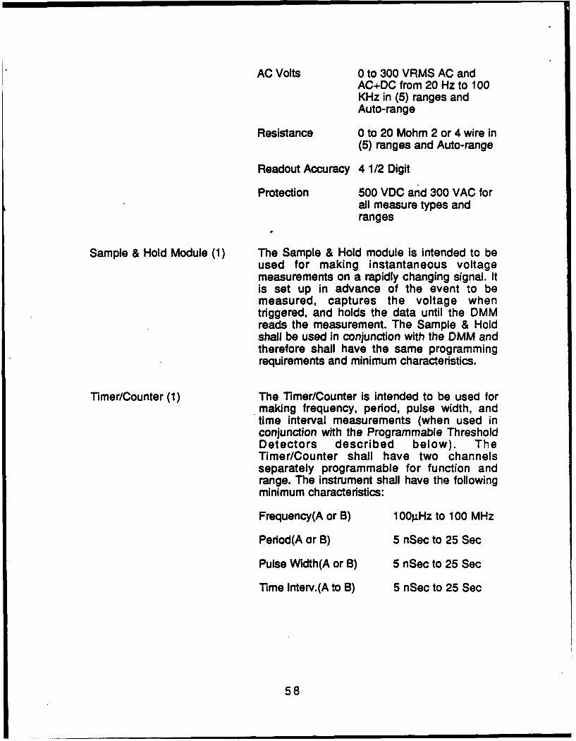
AC Volts 0 to 300 VRMS AC andAC+DC from 20 Hz to 100KHz in (5) ranges andAuto-range
Resistance 0 to 20 Mohm 2 or 4 wire in(5) ranges and Auto-range
Readout Accuracy 4 1/2 Digit
Protection 500 VDC and 300 VAC forall measure types andranges
Sample & Hold Module (1) The Sample & Hold module is intended to beused for making instantaneous voltagemeasurements on a rapidly changing signal. Itis set up in advance of the event to bemeasured, captures the voltage whentriggered, and holds the data until the DMMreads the measurement. The Sample & Holdshall be used in conjunction with the DMM andtherefore shall have the same programmingrequirements and minimum characteristics.
Timer/Counter (1) The Timer/Counter is intended to be used formaking frequency, period, pulse width, andtime interval measurements (when used inconjunction with the Programmable ThresholdDetectors described below). TheTimer/Counter shall have two channelsseparately programmable for function andrange. The instrument shall have the followingminimum characteristics:
Frequency(A or B) 1 001JHz to 100 MHz
Period(A or B) 5 nSec to 25 Sec
Pulse Width(A or B) 5 nSec to 25 Sec
Time Interv.(A to B) 5 nSec to 25 Sec
58

Programmable ThresholdDetectors (2) The Programmable Threshold Detectors (PTD)
are intended to be used to sense a signalexcursion through a programmed threshold.The PTD threshold shall be independentlyprogrammable in level, range, slope, polarity,and AC or DC coupling. (Note: This functionmay be incorporated as a part of theTimer/Counter module.) The PTD's shall havethe following minimum characteristics:
Trigger Level 0 to ±50 V in 2 ranges
Slope + or-
Coupling AC or DC, programmable
Time Delay Generator (1) The Time Delay Generator (TDG) is intended toprovide an accurate indication of aprogrammed time delay with a "TDG complete"logic signal output. The TDG shall beprogrammable for time, range, and trigger. TheTDG shall have the following minimumcharacteristics:
Time Delay 1 g.Sec to 1000 Sec in 5ranges
General PurposeSwitch/Relays (60) The General Purpose (GP) Switch/Relays are
intended to be used for the application ofpower, grounds, and loads to the UUT as wellas the switching of static signals to and fromthe UUT. The GP Switch/Relays shall be SPDTor DPDT latching type, independentlyprogrammable, with all the NO, NC, andCommon contacts available at the ZIFconnectors in the UUT interface panel. The GPSwitch/Relays shall have the followingminimum characteristics:
Contact Current 1 Amp (AC or DC)switched
Switched Voltage 200 Volts
59

Signal RoutingSwitch/Relays (20) The Signal Routing Switch/Relays are
intended to be used to route most of the signalsfrom the UUT to the measurement instrumentsfor processing. The SR Switch/Relays shall beof the SPDT type such that separate floatingpoint measurements may be made. They mustbe independently programmable with theCommon contacts available at the ZIFconnectors in the UUT interface panel and theNO contacts connected to the internal testsystem bus(s). If the characteristics of theGeneral Purpose Switch/Relays (as proposedby the vendor) described above are alsosuitable for this purpose the quantities may becombined and a single type of Switch/Relayspecified. The SR Switch/Relays shall have thefollowing minimum characteristics:
Contact Current 1 Amp (AC or DC)switched
Switched Voltage 200 Volts
High Frequency SignalRouting Switches (12) The High FreqUency (HF) Signal Routing
Switches are intended to be used to route highfrequency signals to and from the UUT. The HFSwitches shall be independentlyprogrammable with the Common contactsavailable at the ZIF connectors in the UUTinterface panel through coaxial connectors andthe NO contacts connected to the internal testsystem bus(s). The HF Signal RoutingSwitches shall have the following minimumcharacteristics:
Voltage 100 VAC , nd 28 VDC
Current 0.5 Amp DC or AC
Bandwidth 50 MHz
Digital I/O Channels (64) The Digital I/O Channels are intended to inputtest vectors and record output patterns from theUUT. The I/O channels shall be available at theZIF connectors in the UUT interface panel with
60

the signal levels TTL compatible and tri-stateable individually or in a maximum of 8-bitgroups under program control. The Digital i/OChannels shall have the following minimumcharacteristics:
VO Rate 20 MHz
Data Depth/Channel 8 K
9.1.4 Additional Requirements/Options
The following additional requirements and/or options must be met by thevendor.
Software
The vendor shall describe in as much detail as possible the softwarerequirements of the proposed system. It is mandatory that the programminglanguage be of sufficiently high order and user friendly so as to avoid thenecessity of programming in machine code, instrument specific ASCII strings,etc. The use of menus or similar programming aids in which the programmerspecifies instrument parameters is desirable.
It is also desirable to be able to generate test programs off-line from thetest station. The software system must also be able to support the programming* of all the other instruments which are not internal to the tester and operate on theIEEE 488 bus. It is required that the system provide a hard copy of softwareprograms and text descriptions/comments to document the test setup andprocedure. Any programming aids or enhancements as well as any debuggingtools which are available with the system should be described. Software trainingfor two should be included as a part of the system cost.
Test Options
The system should provide the operator with a "stop on fail" option whichwill interrupt the test program execution to allow failure isolation while testconditions are maintained. This could make use of one of the operator interfacekeys such that, if selected, a failed condition will automatically cause anindication of the failure and interrupt the test. After isolating the failure, theoperator should then have the option of continuing the test from that point byoperating a push button or foot switch. If the "stop on fail" key is not selected thesystem should indicate the failure but continue execution of the test program.
61
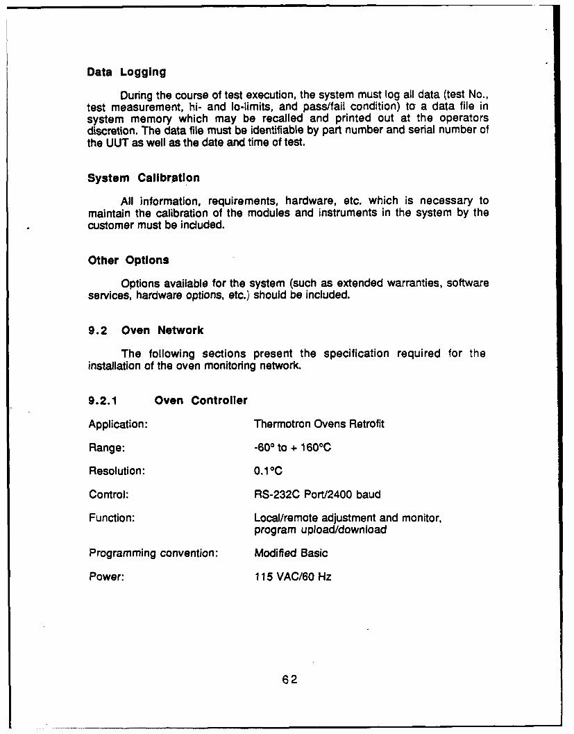
Data Logging
During the course of test execution, the system must log all data (test No.,test measurement, hi- and to-limits, and pass/fail condition) to a data file insystem memory which may be recalled and printed out at the operatorsdiscretion. The data file must be identifiable by part number and serial number ofthe UUT as well as the date and time of test.
System Calibration
All information, requirements, hardware, etc. which is necessary tomaintain the calibration of the modules and instruments in the system by thecustomer must be included.
Other Options
Options available for the system (such as extended warranties, softwareservices, hardware options, etc.) should be included.
9.2 Oven Network
The following sections present the specification required for theinstallation of the oven monitoring network.
9.2.1 Oven Controller
Application: Thermotron Ovens Retrofit
Range: -603 to + 1600 C
Resolution: 0.1 0C
Control: RS-232C Port/2400 baud
Function: Local/remote adjustment and monitor,program upload/download
Programming convention: Modified Basic
Power: 115 VAC/60 Hz
62

9.2.2 Network Controller
Computer: PC (or compatible) w/512K RAM, floppy disk
Display: Monochrome (12")
Interface: RS-232C (one port per channel) - 2400 baud
Printer: 80 column (min) dot matrix
Program Control: DOS/Basic
63

SECTION 10
TOOLING
As a result of the nature of the design and development efforts, there isno unique tooling required for ITM Project 82.
64

SECTION 11
VENDOR/INDUSTRY ANALYSIS/FINDINGS
The Vendor/Industry Analysis/Findings for ITM Project 82' centered ontwo areas of improvement, as dictated by the project objectives:
* Automatic Test Equipment (ATE)* Bum-In Oven Monitoring Network
The following sections describe the vendor search procedure, theequipment selection criteria and the resultant selection made by the projectteam in the execution of ITM Project 82.
11.1 Automatic Test Equipment (ATE)
This section describes the Vendor/Industry Analysis/Findings for a hybrid(analog/digital) test station to be used in FM & TS primarily for sub-assemblytest.
11.1.1 ATE Vendor Survey
Among the vendors supplying Automated Test Equipment to theelectronics industry, fourteen provided equipment specifications for review. Asummary of the ATE manufacturers' survey is presented in Figure 11.1.1-1. Abrief description of each of these ATE systems is provided in the followingparagraphs.
ATE Systems International
Beaver, from ATE Systems International, is a low cost functional testerthat can test a wide range of digital, analog, and mixed boards. Beaver hasbuilt-in analog and digital test facilities plus the ability to control externalinstruments. These can be mixed together freely on boards which require ananalog input to give a digital output or vice versa.
Beaver programming is performdd via an ATE System International-specific programming language which is menu driven.
The current cost for the Beaver system includes basic digital capabilitiesand programming support for IEEE 488 instrument add-ons.
Compu Gen
The Sleuth ATE Analog/Digital Test System, from Compu Gen, is ageneral purpose analog/digital functional and in-circuit test system. The system
65

ProgrammingManufacturer Series I/F Type Language
ATE Systems Intl Beaver EC/BON Functional ATE Sys InternalCompu Gen Sleuth EC/BON FunctionaViCT PascalComputer Automation ironman EC/BON Functional MAJICPLUSComputest 8500 BON Functional/lOT MDG (MS-DOS)Digaiog 2020 EC Functional BASIC09 (UNIX)Fluke 3050B EC FunctionaV/Compare TMS (ATLAS/Analog)Gen Rad 227X BON FunctionaViCT CAPSHewlett-Packard 3065 AT EC/BON Functional/lOT VOL/HP-BASICMarconi Checkmate EC FunctionaViCT Pascal BasedSummation Sigma Series EC Functional Testwindows/TestBASICTalon 100 EC Functional BASICTeradyne L21 01 EC/BON FunctionaViCT Pascal BasedWatkins Johnson 15XX EC Functional COLT (UNIX)Zehntel 800 Series BON lOT Producer (UNIX)
Notes: i/F - Interface with UUT.EC . Edge ConnectorBON - Bed of Nails
Figure 11111 ATE Manufacturer's Survey
66

is highly programmable and reconfigurable. Both test programs for the systemand the system software are written in the standard Pascal language. Highercost system instruments have been avoided and measurement functions havebeen implemented using chip-level or board level modules.
System electronics resides on printed circuit and wire wrapped modulesinstalled in an EXORbus cardrack. EXORbus compatible modules includecustom relay multiplexer, relay driver and scaling/instrument-selection modules,custom wire-wrapped modules implementing a number of instrument andstimulus functions, custom interface modules, and D/A and ND modules. Othercomponents for providing stimulus are mounted outside the EXORbus rack andin the UUT-specific test heads.
The Sleuth ATE system with analog capabilities includes voltage andfrequency measuring capabilities along with threshold comparators and aprogrammable function generator. All instrument drive is programmed via aPascal derived IEEE language.
Computer Automation
Ironman, from Computer Automation (CA), is a completely integrated testsystem which is based on a CA concept called "testsharing." With testsharing,all of the elements of the test process - functional testing, test programming,logic simulation, board repair, and manufacturing management - are alldesigned to work together for optimum efficiency. At the same time, theseindividual capabilities are modular in design so that only the required elementsneed be purchased. This may range from a single test station to a completemulti-station system under the control of a- central processor.
The Ironman is a functional tester which interfaces with an edgeconnector and/or bed of nails. The Ironman can be tailored to individualrequirements through the selection of up to 1024 pins for digital functionaltesting at 10MHz test rates. 10MHz pins can be combined with static, 2MHz and5MHz pins as needed according to the application. A mix of pins with fixed TTL,programmable logic levels, and analog pins are available. The system is alsocapable of external clock synchronization of up to 40MHz. Behind each of thehigh rate pins a 16K x 4 RAM allows the storage of large test programs.
The programming for the Ironman is performed using a languagedeveloped by Computer Automation called MAJIC PLUS. This language usesEnglish-like stateidtents which allow test engineers to describe test programsfunctionally. Logic simulation options as well as non-simulation optionprogramming is also available.
This system is principally a digital tester with "add-on" analogcapabilities.
67

Computest
The 8500 Performance Board Tester, from Computest, is acomprehensive functional/in-circuit test center with the principal featuresnecessary to cause a digital or hybrid circuit card to perform at ratedspecifications for go/no-go testing and provides full automatic guided probefault isolation for defective digital boards. A wide range of diagnostic tools areavailable for fault isolation including signature analysis, voltage, frequency,current probe, and others.
The operating system for the 8500 is an IBM PC/AT compatible MS-DOSoperating system which allows any MS-DOS compatible computer to become aprogramming workstation. Test program generation is performed using MDGfor writing functional tests in a matter of days which can be verified off-line usinga simulator provided with the system.
The 8500 Performance Board Tester includes a digital bed-of-nails testerwith 256 driver/receivers in addition to an instrumentation section with voltage,frequency, pulse catching, and signature analysis.
Digalog
The Digalog 2020 ATE system, manufactured by Digalog Systems Inc.,combines digital and analog test to form a functional performance test system tohandle complex VLSI board designs as well as sophisticated analog circuitry.
The digital test system uses dynamic bus emulation techniques for real-time testing of bus structured LSINLSI printed circuit board assemblies. Thedigital module can be configured to emulate microprocessor bus structures thathave up to 32 address, 32 data, 16 control, and 8 clock lines. The analog testsystem is a self contained modular subsystem operated by the TestheadController located within the computer system. A library of functional calls,contained within a 32kByte EPROM, actually controls the analog systemhardware (e.g., RUN DA[channel, voltage]).
Programming functions include the creation and loading of projects andmemory modules, inter-project file copying, deletion of files, comments editing,and acce., to Basic09 (Pascal and C are optionally available). Filedevelopment and handling are managed together to form a user-friendly digitaltest program development system.
The Digalog 2020 ATE system is available with variations from straightanalog testing to a basic hybrid station capable of microprocessor control andemulation.
68

Fluke
The Fluke 3050B is described in Section 11.2 below and is proposed forimplementation in the "To-Be" FM & TS operations for the test of assemblieswhich are primarily digital in nature.
Gen Rad
The GenRad Model 2750 series is a hybrid test system capable of testingboth digital and/or analog circuitry in either functional or in-circuit modes. Thesystem is configured by the addition of driver sensor cards for digital testing andanalog function cards to allow measurement of AC and DC voltage, frequency,capacitance, inductance and resistance, internal sources of AC and DC voltagefor circuit excitation as well as nine types of integral DC power supplies areconfigurable. For measurement of functions not handled by the internalinstrumentation, an IEEE 488 interface is provided.
GenRad provides a series of high level programming methods includinga package called Genesis which operates on an icon-driven user interface.Additionally, packages are available to provide transition for users of GR179Xand 227X model testers.
The GenRad 2750 tester is a comprehensive system providingexpandability for the user who needs a wide variety of digital capabilitiescoupled with analog testing.
Hewlett-Packard
The 3065 AT, from Hewlett Packard, is a combination in-circuit andfunctional tester capable of testing digital and analog circuitry. The systemprovides hybrid testing capabilities with on-board stimulus sources providingAC and DC voltage and current as well as sine, sequence, and triangle waveoutput. Analog detectors permit measurement of AC and DC voltage,resistance, frequency, and pulse width. The system can internally control up toeight programmable DC power sources and externally any IEEE 488compatible device can be connected. Since the system is a rack-mountconfiguration, instruments can easily be physically located within the testerenclosure.
A large variety of software is available for the 3065 to provide both testprogramming capabilities in addition to networking and information systemssupport for quality and management data processing. Internally, test programsare developed using a BASIC-derived language ir conjunction with both in-circuit and functional program generators. Several aids are available forautomatically generating digital code via simulator and graphically displayingtest results. Interfaces are available for input of testing patterns via computer
69

aided engineering links. Testing software can also be assisted through integralsignature analysis routines.
Marconi
Checkmate, manufactured by Marconi, is a comprehensive, low costbench top configuration of Automatic Test Equipment. The range of functionsprovided is configurable by plug-in cards covering analog and digital testing,using in-circuit and functional test techniques together with logic and waveformanalysis. Up to 21 cards are accommodated in one frame and can be usedindividually or in any combination.
The operating system for the Checkmate ATE is based on CP/M. All thefacilities for each instrument card are contained in on-board firmware and aremanaged by an on-board microprocessor. Each instrument card downloads itsown unique profile to Checkmate's operating system and provides theprogrammer with a menu of available facilities. This has the advantage thateach instrument is under the control of its own processor, thus reducing theoverhead on the main system processor and increasing the test executionspeed.
The Checkmate system includes a basic digital capability which is theprimary system feature along with analog instruments and an IEEE interface.
Summation
The Sigma Series Test System, from Summation, is a complex digitaland analog functional tester. The system includes a MC68000-based modulartest station and an IBM PC computer, in addition to the proprietary TestWindowssoftware.
The high speed digital test system consists of function modules whichplug into the Sigma Series TestFrame and a special software package that runswithin TestWindows on the IBM AT. The TestFrame's MC68000 processorcommunicates with the IBM AT over the IEEE 488 bus and controls the testsystem. Other buses within the TestFrame provide inter-module triggering andanalog signal switching capability. The TestFrame and all modules are at asingle address on the IEEE 488 bus which operates at DMA rates up to 300Kbyte/second.
Analog measurement and stimulus modules like waveform recorders,counter-timers, and function generators can be used right along-side the highspeed digital test modules. The system's bus structure allows triggeringbetween these modules. Static digital I/O modules and a variety of switchingmodules can be added if needed. Up to 23 instrument modules can beintegrated into one compact test system.
70

Summation's TestWindows development system and TestBASIClanguage provide fast program development, debugging, and documentationfor IEEE 488 instrument control applications. This is a menu-driven, very userfriendly system which uses a "mouse" interface and highly sophisticatedwindowing software.
Talon
The Model 100, manufactured by Talon, is a compact, general purposefunctional tester. The system contains twelve 16-channel "instruments", cross-triggered by any of four timing generators or controllers. The Model 100 may beused with other ATE instrumentation either via a host computer or through aLocal IEEE Control Interface option which allows the Model 100 to directlycontrol IEEE 488 compatible auxiliary instruments such as- programmablepower supplies, multimeters, etc.
The Model 100 has an on-line BASIC-like interpreter. The entireinstruction set appears in pop-up windows to guide the user through eachinstruction entry. The resulting instruction is displayed on the CRT and isdirectly executed when commanded.
The Model 100 system includes the basic digital system of 192 I/O driverswith an IEEE 488 interface and software. Analog instrumentation andintegration would be the responsibility of the user.
Teradyne
The L210i, manufactured by Teradyne, is an advanced, integrated in-circuit and functional test system which can achieve high fault coverage onVLSI boards. Internally, the L210i is organized around three major functionalgroups: the computer group, the digital subsystem, and the analog subsystem.
Within the computer group, a DEC PDP-1 1 serves as the supervisoryprocessor. This communicates with the digital and analog subsystems wherededicated processors execute analog and digital instructions. The digitalsubsystem includes the Digital Command Processor, dynamic test controllers,digital channel cards, and system diagnostic tools. The analog subsystem,controlled by an Analog Instrumentation Processor, accommodates a widevariety of analog instruments and programmable power supplies. Analoginstruments are switched over a Kelvin matrix to the board under test.
Test program generation is performed using a Pascal based language.This structured language makes it possible for programmers who may havedifferent areas of expertise to work in parallel, developing distinct programsegments separately, and finally merging them for efficient production testexecution.
71
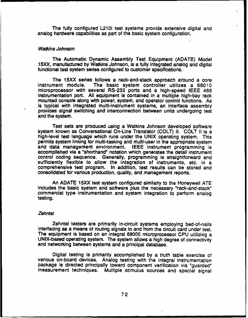
The fully configured L210i test systems provide extensive digital andanalog hardware capabilities as part of the basic system configuration.
Watdns Johnson
The Automatic Dynamic Assembly Test Equipment (ADATE) Model15XX, manufactured by Watkins Johnson, is a fully integrated analog and digitalfunctional test system series configured to customer specifications.
The 15XX series follows a rack-and-stack approach around a coreinstrument module. The basic system controller utilizes a 68010microprocessor with several RS-232 ports and a high-speed IEEE 488instrumentation port. All equipment is contained in a multiple high-bay rackmounted console along with power, system, and operator control functions. Asis typical with integrated multi-instrument systems, an interface assemblyprovides signal switching and interconnection between units undergoing testand the system.
Test sets are produced using a Watkins Johnson developed softwaresystem known as Conversational On-Line Translator (COLT) I1. COLT II is ahigh-level test language which runs under the UNIX operating system. Thispermits system linking for multi-tasking and multi-user in the appropriate systemand data management environment. IEEE instrument programming isaccomplished via a "shorthand" notation which generates the detail instrumentcontrol coding sequence. Generally, programming is straightforward andsufficiently flexible to allow the integration of instruments, etc. in acomprehensive test program. In addition, test results can be stored andconsolidated for various production, quality, and management reports.
An ADATE 15XX test system configured similarly to the Honeywell ATEincludes the basic system and software plus the necessary "rack-and-stack"commercial type instrumentation and system integration to perform analogtesting.
Zehntel
Zehntel testers are primarily in-circuit systems employing bed-of-nailsinterfacing as a means of routing signals to and from the circuit card under test.The equipment is based on an integral 68000 microprocessor CPU utilizing aUNIX-based operating system. The system allows a high degree of connectivityand networking between systems and a principal database.
Digital testing is primarily accomplished by a truth table exercise ofvarious on-board devices. Analog testing with the integral instrumentationpackage is directed principally toward component verification via "guarded"measurement techniques. Multiple stimulus sources and special signal
72

measurement functions such as waveform analysis is carded out by external
instruments on an IEEE 488 bus controlled by the test system.
11.1.2 ATE Selection
The information provided by the ATE vendors was compared to thespecifications detailing the Honeywell ATE performance characteristics toascertain functional compatibility with existing equipment. This was done toassure that the specified equipment could perform tests on existing devices inthe event Honeywell equipment was no longer available. In addition, TestEngineers in the FM & TS Production Engineering Department were consultedin an attempt to establish additional station requirements that would benecessary to test future designs. A general specification was developed as aresult of this process and is presented in Section 9 of this document.
A comparison between the general specification and publishedspecifications for the surveyed equipment was performed and tabulated in theATE Requirements Matrix presented in Figure 11.1.2-1. This assessmentprovided the basis for determining the appropriate course in future ATEselection. The systems described in Section 11.1.1 which could meet thesecriteria included:
0 ADATE 15XX Test System
* Compu Gen ATS Senies
* Digalog 2020 Series
0 GenRad 2750
* HP 3065 AT
0 Summation SigmaSeries
* Teradyne L210i
Since FM & TS future requirements can consist of both the technologyemployed as it is at present as well as more complex designs employing fiberoptics, high speed digital, etc, ATE selection was narrowed to equipment whichhad flexibility through instrument configuration and programming integratingmultiple types of functions (analog, digital, and hybrid) but not requiring a largeinitial investment. The systems described in Section 11.1.1 and exhibiting theability to build around a lower cost system core included:
Compu Gen
* Digalog
Summation
73

> X-XX<XXXX-c.(x0
8C0
cmI
*CL
Sa * -X<- *x~
a* Wyc yc Ci - -C
'IE c
(L 1S0 E -c
Figure 11.1.2-1 Current ATE Requirements Matrix
74

0 0
w E .t 0
-. ,Ln M u) a1 -~ ~ 0
CL 0
E 0
- O1 NS E~ a I
00
b 0 0
a .oM =~o
Figure 11.1.2-1 Current ATE Requirements Matrix (Cont.)
75

Cost effectiveness was a key consideration. Generally, ATE units with ahigh degree of flexibility carry significant costs, fenerally in hardware.However, a newer generation of equipment is emerging which integratesinnovative programming techniques with a hardware approach that significantlylowers total costs.
This equipment combines integral instrumentation (for commonfunctions) with the traditional "rack and stack" approach, coupled with menu-driven programming to achieve both low cost and versatility. The hardwareextensions to the basic tester are accomplished through the use of thecommonly accepted IEEE 488 buss convention allowing the use of virtually any.instrument produced at present.
This overall combination of software and hardware, coupled with lowcosts, is presently available through one vendor, Summation, although thereare indications that others are migrating toward this approach.
Typically, the Honeywell ATE configuration can be implemented in theSummation product line for far below estimated replacement costs andsignificantly less than other ATE manufacturer's equipment for equivalentfunctions. Additionally, there is no equipment presently in the marketplaceemploying the comprehensive programming approach found in Summationequipment which is as inexpensive and detailed.
Since programming can result in costs an order of magnitude higher thaninitial equipment costs, the approach which affects this expenditure areasignificantly reduces overall cost of ownership. The need to maintain existingtest capabilities on higher volume spares could necessitate programming thesedevices on the replacement ATE system in the future. As indicated, thiscapability can be economically incorporated into the equipment acquisition.
The following section presents a detailed description of the SummationSigmaSeries test system.
11.1.3 Summation SigmaSeries Test System Description
Summation's SigmaSeries' T Test System family fulfills the majorrequirements of the Computer Integrated Test (CIT) systems needed in today'smanufacturing environments with:
* Complex analog and digital testing
* Simple straightforward operation
* Powerful software development tools
* Rapid test system reconfiguration
76

* Fast data feedback through networks
• Data reduction and statistical analysis
* Networking capability
* Management information system gateways
The system includes the MC68000-based modular TestStation TM , proprietaryTestWindowsTM software, and an IBM computer.
11.1.3.1 Summation Approach
Summation has a unique approach to ATE configuration and testdevelopment. Traditionally, final test systems were built from discreteinstruments designed for engineering applications. These systems werecustom built and programmed from instrument controllers via the IEEE 488standard interface bus.
The SigmaSeries is the first testing system designed specifically for finaltest. It provides comprehensive testing benefits which include:
* Dramatically reduced development time
0 Automated program documentation
0 Combined analog/digital capability
0 Combined integrated triggering and switching
0 High speed communication
* Simplified data recording
0 Straightforward operator interface
The SigmaSeries dramatically reduces the time and effort required todesign, program, debug, and install a final test system. The modularTestStation contains all measurement, stimulus, and switching hardware.Therefore, test system design only requires function selection. TestWindowsreduce programming time as much as 80% through innovative graphicaltechniques. Once the test procedure has been written, special TestBASICTM
features allow rapid revision and correction. Finally, the compact packaging (7-inch, rack mountable) and centralized fixturing mean quick implementation onthe factory floor.
77

Test solutions are quickly documented. TestBASIC helps structure testprocedure design for automated documentation. On command, the systemprints clear, concise switching and triggering diagrams.
The SigmaSeries includes both analog and digital test. Each test stationcan be configured with up to twelve functions. Five analog, four digital, andthree switching functions are currently available and new capabilities areplanned. The basic structure of the SigmaSeries integrated test station isshown in Figure 11.1.3.1-1. As can be seen in this diagram, in addition to thecross triggering of modulos in the test box, the SigmaSeries can evenaccommodate other manufacturer's instruments which contain IEEE 488standard interfaces.
The SigmaSeries substantially eliminates ground loops and noisethrough proprietary CrossTrigger m and TestPath'm signal buses integrated intothe modular TestStation.
11.1.3.2 Shop Floor System Design
The SigmaSeries has features and functions which make it practical forthe FM & TS manufacturing environment. These include:
Versatile, reconfigurable hardware
0 Clear display and audible signal
0 Simple operator interface
* Reduced cabling and fixturing
* Compact, rugged design
100% reliability tested
The modular TestStation hardware is attractive for many difficult testingtasks. Final, sub-assembly, and design-environmental test are idealapplications. The system is completely reconfigurable: the operator can changetest routines, system configuration, and data output options at the touch of abutton. Therefore, one SigmaSeri, s system can perform multiple roles in thesame location.
The SigmaSries provides flexible options to prompt -the operator.Messages can appear on the IBM computer monitor, the TestStation 80-character display, or they can be heard from the audible beeper. The IBMmonitor serves best for complicated prompts, such as graphical representationsor waveform displays. The simpler TestStation display is ideal for GO/NO-GO orother less complex testing. Also, whenever it would be inefficient for the
78

Other Test &MeasurementI nstrumet
TestStation
IEEE 488 TsDMA Ts
CommunicationsFrm
RealtimeMulti-tasking
Operating System
Moule -- *C
1-CDCMCM
Mod0)
Figur 11..3 1 SiMadueisTs oueItrae
X-NO Swith79

operator to look away from the Unit Under Test, the audio annunciator providesthe feedback.
The operator can respond to prompts in two ways: the TestStation keysor a footswitch. Seven keys on the TestStation (all soft programmable) allowthe operator to change tests or configuration, select options, or halt testing. Thefootswitch is especially useful for incrementing to the next test step after makingan adjustment or connection which requires the use of hands. In either case,fewer keys reduce operator confusion and errors.
The TestStation design minimizes the number of system cables andfixtures. The internal CrossTrigger and TestPath buses eliminate most intra-system connections while single-location patching precludes many additionalUUT connectors.
The compact, rugged design of the SigmaSeries offers convenientoptions for test bench construction. The IBM computer and/or the TestStationcan be placed in remote locations (for example, beneath the bench). Thecomputer display is completely optional during test operation. A single,compact SigmaSeries system can free up much -needed space by replacingseveral expensive, dedicated testers. A rack mount industrial computer,manufactured by IBM for Summation, is also available.
11.1.3.3 Data Analysis Capabilities
The SigmaSeries meets the growing demand for reporting of final testresults. Its built-in features provide:
Reliable bar code data input. The bar code reader enters failure codes,UUT serial numbers, operator identification, or other important variableinformation for use under program control.
Strip and full-size printer output. A strip printer output can be attached toUUT's paperwork as a record of failures and aid in troubleshooting. Printing,rather than manually recording the failure, saves valuable test time. TheTestStation has both RS-232C serial port and a Centronix-type parallel port tosupport a wide variety of printers.
Standard data format files. Data Interchange Format (DIF) files allow anyone of hundreds of data reduction programs to analyze the data at the bench.Test data can be converted from the SigmaSeries to DIF automatically, andthen analyzed using spreadsheets, plot programs, trend analysis programs, orother statistical programs which accept DIF information.
Compatibility with IBM and SigmaNet. Current SigmaSeries systems arecompletely compatible with the SigmaNet local area network (based on IBM-standard networking hardware and software). Therefore, data can be shared
80

between test systems. Because the SigmaSeries uses a standard IBMcomputer, the system can utilize IBM-compatible software and hardware.
A conceptual view of the integration of the SigmaSeries test equipment ispresented in Figure 11.1.3.3-1. As shown in this diagram, SigmaSeries teststations can be interfaced via network to a centralized program library in asimilar manner as currently employed where the Honeywell ATE's are linked toATE Central.
11.1.3.4 Programming Summation Equipment
Summation's TestWindows development system and TestBASIClanguage provide fast program development, debugging, and documentationfor IEEE 488 instrument control applications. This advanced software systemcan be used with any IEEE 488 instruments from any vendor.
TestBASIC provides a DOS based PC/AT compatible computer with thesame instrument control power as a dedicated instrument controller.TestBASIC also contains many features not found in typical instrumentcontrollers, such as:
* Structured-programming constructs
• IEEE 488 command generator
* True sub-routines, libraries, and functions
* C language routine calls
* Paint and Draw generated graphics calls
* Trace, break, and single step debuggers
* Documentation tools
Simplified Programming Steps
The following steps represent the ease of programming using theSigmaSeries Tester. First, use the TestBASIC editor to outline the program.TestBASIC's highly structured environment and straightforward syntax makesthe code highly readable.
The operator then selects the IEEE 488 instruments to perform each test.TestWindows includes a set of instrument windows and others can be added.With multiple windows on the screen, several instruments can be programmedsimultaneously.
81

CE CorporateCMSsem Mainframe Ssem
Test and Program,. .. Generation Station
and File Server
-t Test Engineering
Department
Manufacturing Floor
. .-. .. ........ .........
Figure 11.1.3.3-1 SigmaSerles Network Integration
82
As an aid to writing the program, TestWindows has an ImportP functionto generate IEEE 488 code automatically, eliminating the need for manuals orreference cards. TestBASIC code is automatically generated and documentedfor each instrument set-up. Program variables, IEEE 488 bus traffic, sourcecode execution can be traced using the TestBASIC runtime support feature.
The test program can then be documented and integrated. TestWindowsallow for the use of graphics for guided-probe troubleshooting, documentation,and training. Other software packages can be integrated for word processing,spreadsheet analysis, and additional requirements.
TestWindows Automated Programming
TestWindows software provides the simplest user interface available.Function "windows", analogous to instrument front panels, control all displaysand test settings. The user can "point and click" with a standard mouse interfaceto make selections, add functions, or program tests. Total proficiency isachieved in a matter of minutes.
Because of the completely integrated nature of the SigmaSeriesTestStation, system configuration is programmable. The test engineer canmodify switches, trigger lines, and function settings at the touch of a button.
TestWindows operates either in immediate mode, controlling theTestStation hardware interactively, or in programming mode, utilizingTestBASIC. However, both modes can operate simultaneously for automatedprogram generation or modification. The TestBASIC editor window can beopened and used interactively with the "front panel" device windows. The usercan also develop tests without the TestStation: only TestWindows and the IBMcomputer are required.
Automated function programming eliminates manual and mistakes fromtest development. After the windowed "front panel" settings are verified, a clickon the mouse automatically generates the correct program line and the ImportTmfunction transfers it to the TestBASIC program. Conversely, functions settings ina TestBASIC program can be transferred directly to a "front panel" window forgraphic verification of program content.
Extensive built-in "debug" facilities reduce the time to perfect testprograms. Trace functions highlight program execution while monitoring thevalue of a program variable, sub-routine location, and/or IEEE 488 bus activityon the screen. Conditional breaks can continuously test an expression for atrue condition. The system can display TestStation hardware conditions at anytime, allowing the engineer to check for errors in test set-ups.
TestBASIC solves the structure problems of BASIC programs which oftenlead to poor documentation and difficult maintenance. TestBASIC includesAutoindexing m and true sub-routines with local variables and recursive entry.
83

These features promote top down design and allow automatic documentation.Autoindexing provides a test procedure flow outline in English (even beforeentering any executable statements). Common sub-routine constructs can beused over and over in different programs.
TestBASIC Development Language
TestBASIC simplifies test programming and includes a screen-orientedEditor Window, Output Window, and a variety of pull-down menus and pop-upwindows. The CRT screen can be arranged with all of these interactivewindows.
The editor window allows sub-routine, library, and function creation andmanipulation. It also supplies cut/copy/paste and search/replace operationsunder an "Edit" menu. The Output Window contains text and graphics for run-time operator prompts.
Available memory is the only limitation to TestBASIC program size.However, program chaining and libraries allow virtually unlimited length.
TestBASIC incrementally compiles each line of code as it is entered.Thus TestBASIC immediately detects keystroke or syntax errors. TestBASICcreates both an ASCII source version and a binary version of each applicationprogram. Only the programmer's PC/AT needs to contain the source code.
TestBASIC is a powerful, complete programming language. Itscomprehensive set of statements eliminate the need for specialized andconfusing commands. It also allows the use of one BASIC language for allinstruments, regardless of vendor.
TestBASIC constructs, such as DO-WHILE, IF-THEN-ELSE-IF, andSELECT-CASE allow Pascal-like structured programming. Labels and linenumbers are optional.
Sub-routines provide a reusable format for commonly used software.General purpose routines can be written such as pass/fail tolerancesverification, report generation, IEEE 488 service request handling, instrumenterror handling, timed interrupts, status checking, and instrument initialization.
These routines may be semi-independent sub-routines (CALL),independent library routines (LIBRARY), or dependent branches with returns(GOSUB). The sub-routines and libraries use local variables which are passedby reference. The GLOBAL command allows global variables to be defined forsub-routines.
An option allows programs to be written in "C" and Assembly Languageroutines and run from the TestBASIC program.
84

TestWindows Test Development Environment
A set of windows exists for each instrument. These instrument windowseliminate the need to reference instrument IEEE 488 programming manuals.The instrument window represents either a Summation SigmaSeries TestSystem module or any vendor's IEEE 488 instrument. The SigmaSeriesinstrument and switching module windows consist of a combination of graphicsand English text. Mouse clicks on icons or "pushbuttons" manually control themodule. Windows for other vendor's instruments consist of user-definedEnglish set-up commands.
Summation provides windows for the TestBASIC editor, TestBASIC run-time system, DOS files, Summation SigmaSeries function modules, and theIEEE 488 Window Generator. Summation also supplies sample instrumentwindows for IEEF 488 instruments. The Summation Users' Group maintains alibrary of windows. With the TestWindows package comes a variety ofMicrosoft-supplied windows (Paint, Write, and Calculator functions are amongthose supplied).
The Summation IEEE 488 Window Generatorm provides unprecedentedflexibility. Creating a window for an instrument of average complexity requiresonly a few hours. The process consists of equating each vendor-definedinstrument command to an English command of your choice. One Englishcommand can be equated to an instrument set-up. The instrumentprogramming manual is needed only during window creation.
11.1.3.5 Debugging and Documentation
Debugging
TestBASIC provides the only interactive , on-line debugging environmentfor instrumentation control. Advanced tools include:
• Trace Code
* Trace IEEE 488 bus
* Trace Variable(s)
* Trace Uninitialized Variables
* Trace (sub-routine) Stack
* Trace Break Conditions
* Set (unconditional) Breakpoint
85

* Single Step
Next Step
Continue At
• Continue
Trace code scrolls the executing program and highlights the executingline of code. Other windows can be tiled on screen to simultaneously monitorthe status of the instruments, to Trace Variable values, and to Trace IEEE 488bus traffic between the computer and all addresses. This unique interactivenature of Windows quickly isolates the problem area, making it possible todebug without listings.
Documentation
The TestWindows environment decreases documentation time. Tiesbetween Microsoft and Summation Windows packages combine existingdocumentation, UUT measurements, and Paint generated drawings.
SigmaSeries instrument commands appear in English. Commands forother IEEE 488 instruments appear as specified by the manufacturer, andTestBASIC adds user-defined English equivalents as comments to thecommand. Clear variable names and branch labels make the BASIC languagereadable. The program can be listed in three ways:
Comments only
Executable code only
Combination of both
Text and graphics can be easily combined. Summation's Camerawindow cuts any section of the screen contents. The screen contents couldrange from a waveform measured with a SigmaSeries waveform recorder to acabling set-up diagram in the Microsoft Paint window. The Camera buffer canbe pasted in a Microsoft Write file. The Write file could contain thecorresponding TestBASIC program source or user written documentation text.
11.2 Additional "To-Be"' Automated Test Equipment (Fluke 3050B)
Since the Honeywell ATE has limited digital card testing capabilities, FM& TS began digital card program development and testing on a FlukeFunctional Test System in 1979. This tester was acquired by the CommercialAvionics Division and has been available to FM & TS on an off-shift basis forshared use testing of digital cards since that time. However, as the Commercial
86

Avionics Division completes their move to a new facility, this tester will becomeunavailable.
Therefore, in order to maintain the present test capability and provide forthe future, it is proposed that for the "To-Be" operation FM & TS purchase adedicated Fluke 3050B for digital card testing. This will allow for the continuedtesting of products whose tests were originally developed on the CommercialAvionics Division's tester and assure that testing of the more complex digitaldesigns of the future will be possible.
The need for such a tester was identified early in the Phase 2 activity ofITM Project 82. Therefore Production Engineering began an immediate searchfor the equipment. As a result, an appropriate used Fluke 3050B tester waslocated and ordered in July, 1987 and received in September, 1987.
11.3 Burn-in Oven Monitoring Network
System criteria for the Burn-In oven monitoring network equipmentconsists of standardized controllers, simple programming, ease of networking,and reasonable cost. Since the existing Thermotron ovens are proposed forretrofitting, vendors with equipment which would easily interface with theseovens would be a requirement.
A review of vendors indicated that most network interconnection occursvia RS-232 (or similar protocol). This simplifies the interconnection of unitssince an easily fabricated cable consisting of a few conductors can interfacebetween each oven and the system controller.
In addition, simplified programming was considered to permit ease ofsystem maintenance and revision. In this area, most vendors supply aprogramming package consisting of a BASIC (or very similar) command set.Since this language has wide acceptance and ease of use, the monitor systemdoes not require the constant services of a system programmer. Moreover, theuse of a language with a common structure, in a PC MS-DOS environment,would allow future networking to be accomplished much more readily.
Three vendors were located that had equipment with the desiredperformance characteristics. They were:
J.C. Systems
Sun Systems
* Thermotron
J.C. Systems manufactures environmental controllers and various controlpanels adaptable to Thermotron ovens. The controllers are network adaptable
87

and can be fitted into the existing physical locations. Programming isaccomplished via BASIC-like commands and controlled by a standard PC.
Sun Systems provides a control panel for retrofit which interfaces ovensto a monitor point via RS-232. Control is via a standard PC (or PC compatible)utilizing a BASIC-derived command language.
Thermotron, which originally manufactured all the ovens utilized in FM &TS for device bum-in, produces a panel which can retrofit into the existingovens and consists of the network, protocol, and language features required forthis application. An additional benefit is Thermotron's maintenance of filescovering all ovens sold to Honeywell. This permits an accurate assessment ofthe ovens and specifics about the peculiarities of each oven.
Response to requests for quotation for the monitoring system has beenvary limited, with the only quotation coming from Thermotron. Therefore, theThermotron system is the choice for this equipment at present. Because of thelimited response additional vendor searches may be performed prior toimplementation.
88

SECTION 12
EQUIPMENT/MACHINERY ALTERNATIVES
12.1 Summation Test System
In the event that the Summation Test System specified is not available orproves unable to satisfy FM & TS requirements, no clear alternative immediatelypresents itself. Since the ATE industry in general is at present experiencingsuch technological growth, additional equipment search and evaluation wouldbe in order.
12.2 Fluke 3050B Test Station
The Fluke 3050B test station was ordered in July,1987 and delivered inSeptember, 1987. Therefore, alternative equipment is not a consideration.
12.3 Burn-ln Oven Monitor Network
If the monitoring scheme proposed proves unsatisfactory or isunavailable, the search for another vendor would be continued and/orexpanded. If no comparable system were found, the present method of manualmonitoring of the ovens would be continued. However, part of the proposedsystem consists of the u, prade of the individual oven controllers tomicroprocessor based uinits. There is no reason to believe that this portion ofthe proposed upgrade could not be accomplished since the controllers alreadyexist and are readily available. This approach would eliminate the monitoringnetwork but still extend the oven life by eliminating switches, motors, andassorted wear-prone mechanical equipment that presently exists in some of theovens.
89

SECTION 13
MIS REQUIREMENTS/IMPROVEMENTS
The most significant improvements in the card and device testing area inrespect to the Honeywell MIS department will be achieved with the introductionof the HMS/BOS system currently being modified for use at the St. Louis Parkfacility. HMS is a modular system comprised of the following modules:
* Master Production Scheduling (MPS)• Inventory Records Management (IRM)* Manufacturing Data Control (MDC)* Material Requirements Planning (MRP)• Capacity Requirements Planning (CRP)• Purchase Material Control (PMC)* Production Cost Accounting (PCA)
In addition to HMS, Honeywell is also implementing a process layout systemwhich includes the Process Management System (PMS) and the Factory DataCollection (FDC) System.
The Factory Data Collection (FDC) system has been developed as ameans of automatically recording hours an employee expends on a specificoperation/part number. This provides important information to FM & TSmanagement both for accounting purposes as well as monitoring thepercentage of completion of a specific part being built. It is envisioned that inthe future, the FDC system will be expanded to provide input to a system forlocation tracking of work-in-process as well.
Honeywell is also developing the specifications for a Work CenterManager System (WCM). While these specifications are still in thedevelopment phase, the improvements described in this document take intoaccount the eventual implementation of these efforts and have been designedfor future interface to a Work Center Manager System. The followingparagraphs describe the basic functionality required of the Work CenterManager System.
A Work Center Manager System is typically a major piece of ahierarchically structured computerized factory control system. Residing at ahigher hierarchical level than the WCM are the corporate systems and the MRPand MRP II systems such as HMS/BOS. Because MRP II systems are batchprocessing operations, the Work Center Manager has been assigned theresponsibilities of direct, real time control of the factory floor. In this role, thesystem is responsible for short term, global schedulirg tasks (during theoperating day) and coordinating the inter-cell operations (such as materialhandling "hand-offs") that reside below it in the controls hierarchy.
It is also envisioned that the Work Center M,,,Pager will distributegraphics and textual process data to workstations and v.'.d maintain a process
90

data library which will be accessed by various pieces of the process controlhierarchy (such as PLC's and other automated equipment).
Implementation of the recommendation to upgrade ATE equipment willrequire the establishment of a data network to intorconnect test andprogramming stations along with development of a centralized database similarto ATE Central to maintain configuration control of test programs. As newsystems are moved to production and additional test stations are placed intoservice, this network will gain in importance to FM & TS.
Since FM & TS will continue to support programs now in existence, theexisting ATE Central and a complement of Honeywell ATE consoles will berequired for several years to come. It is assumed programming will enter a"maintenance" phase and emphasis will shift to the newer equipment describedpreviously.
91
SECTION 14
COST BENEFIT ANALYSIS AND PROCEDURE
In analyzing ITM Project 82, attention was focused on the methods andprocesses utilized in the FM & TS card and device areas. Activities reviewedincluded testing and production of cards, devices, and spares for the various FM& TS programs.
In the initial stages of the project, several areas were identified as costdrivers and reviewed for possible savings using the methodology shown in theprocess diagram of Figure 14.0-1. Those that exhibited the greatest potential forimprovement were:
* Rework/Retest
Programming Costs
Troubleshooting Costs
Areas identified from the contract ledger data and foreman's cost controlreports which did not result in significant benefit were:
* Scrap
Standard Hours
The relatively low annual volumes in ITM Project 82 resulted in virtuallyno scrap. This is primarily because the effect of any scrap action would be theloss of a device or card and subsequent schedule impact. Consequently,rework is the preferred altemative.
14.1 ITM Project 82 Cost Drivers
The following paragraphs describe the cost drivers for ITM Project 82.
Rework/Retest
Examination of cost control records revealed that most of theRework/Retest hours expended during 1986 were the result of retest due to E.O.(Engineering Order) incorporation and rework/retest due to component failureduring testing and burn-in. Since neither of these cost drivers are affected byITM Project 82, no rework/retest savings are projected as a result ofimplementation of the proposed equipment.
92

~ii
00
00C
~LmE
co 0
L !
Figure 14.0-1 Cost Benefit Analysis Methodology.
93
_____________________

Programming Costs
Current FM & TS program testing is baded on the fast development of testsequences for each device and the individual cards contained in them. With theexception of tests performed on certain Targeting Systems, all major systemshave been programmed on Honeywell ATE units.
A typical device program will contain thirty to forty segments which arecreated and maintained by a production test engineer. Individual cards,numbering ten to twelve per device, require additional test engineering time forcoding, debugging, and certification of the test program. As a result, the"typical device consumes over 1-1/2 man-years in programming alone.
Because of efficiencies available in the programming systems which arepart of the proposed ATE equipment, the typical programming effort can bereduced by as much as two-thirds. A conservative approach was taken for thecalculation of savings by assuming that the reduction in effort would be only50%. This benefit comes about primarily because coding, debug,reprogramming, and documentation using the new equipment are much moreeasily accomplished.
The savings to be realized will come about primarily when new businessis introduced in FM & TS requiring the creation of test programs for new cardsand devices. The project team estimates that savings in the programming effortwill occur with the introduction of new programs in the 1989 - 1995 time framebased on projections obtained from Honeywell's Forecasting group. In addition,maintenance of these test programs is estimated to be 20% of the typical newprogramming effort per year in the 1996 - 1999 time frame.
Troubleshooting Costs
During device testing, the troubleshooting activity typically results in coststen times higher than those at the card testing level. This is primarily due to thedifficulty of isolating faults within a device as opposed to those on a single card.
Industry experience indicates that ninety percent of failures are caught atthe printed circuit board level with the remaining ten percent surfacing at thedevice level using functional testing methods employed as they are in the FM &TS area. The result is an almost equal cost for finding and fixing failures at bothlevels. This is in agreement with FM & TS variance hours data taken from thecontract ledger for 1986 for devices and cards on the higher volume programs.
Due to the enhanced troubleshooting capabilities presented by theSummation SigmaSeries test station it is estimated that fault isolation at thecard and sub-assembly test level can be increased from ninety to ninety-fivepercent on new assemblies which come about as a result of new businessintroduced in FM & TS. By increasing detection of faults to ninety-five percent at
94
the card test level, an annual savings of fifty percent will be realized in test at thedevice level.
In short, a fifty percent savings in device test costs can be achieved with afive percent increase in card test costs. For the savings calculations this waslimited to new programs in FM & TS. There is a possibility for additional savingsif it can be demonstrated that the troubleshooting savings realized can offsetprogramming costs on higher volume assemblies in current production.However, since this must be evaluated on a case by case basis by ProductionEngineering as the opportunities present themselves, these potential savingswere not included in the calculations.
Actual Hours
In determining savings for the card and device areas, actual operatingratios derived from Foreman's Cost Control reports were utilized. All standardhours were "normalized" to actual hours to perform "As-Is" versus "To-Be"comparisons on an area-by-area basis. This method is then able to take intoaccount all operational factors not normally included in standards.
Assumptions
All calculations are tabulated for ten yearly periods by quarter, beginningwith the implementation point. Generally, implementation commences during1988, with savings not being realized until 1989.
Production rate increase/decreases are calculated based on the ten yearmarketing forecast for FM & TS revenue projected from factory production. Thisapproach removes sources of revenue not directly attributable to productsmanufactured in the FM & TS production facilities addressed in ITM Tech ModProject 82.
14.2 Capital and Expense
The capital, recurring and non-recurring expenses for Project 82 areshown in Figure 14.2-1.
14.3 Project Savings and Cash Flows
The savings to be realized in this project exceeds Honeywell's MilitaryAvionics Division hurdle rate. The Project's cash flows are shown in Figure14.3-1 with the assumption that capital will be available per the implementationplan.
95

PRWJT 2 EXPENDIfTJRE SUMARY
GROSS CAPITALIZATION GROSS YEARCOST YEAR COST EXPENSED
CAPITAL COSTS EXPENSE COST
AUTOMATIC TEST EOUIPMENT (ATE) COST NON.RECURRING EXPENSES
FLUKE ATE 8,448 1967 TRAININGSUMMATION ATE $210.706 1988 $1,700 1988
so 1989SUB-TOTAL 862.4,8 1987
1210,706 1966 SUB-TOTAL $1,700
COMPUTER COST PROCESS MODIFICATION86,400 1988
OVEN MONITOR SYS $103,966 1988 $4.700 1989
SUB-TOTAL $103.996 1988 SUB-TOTAL $11.100
OVEN MONITOR SYS. PROGRAMMING86,448 1987 $2.600 1988
8314.692 1988 $1,eO0 1989
TOTAL CAPITAL COST 1296140 SUB-TOTAL $4.200
$10,700 1988
$6,300 1969
TOTAL NON-RECURRING $17.000COST
TOTAL CAPITAL AND
NON-RECURRING $415,140
RECURRING EXPENSESANNUAL MAINTAINANCE $11.900
Figure 14.2-1 Project 82 Expenditure Schedule
96

1987 1988 1989 1990 1991 1992 1993
Capital $83.448 $314,692 $0 $0 $0 $0 $0
Non-Recurring Expense $0 $10,700 $6,300 $0 $0 $0 $0
Recurring Expenses $0 $2,500 $11,900 $11,900 $11,900 $11,900 $11,900
Savings $0 $0 $74,002 $105,989 $146,886 $284,479 $414,691
Depreciation $10,431 $54,991 $80,580 $65,634 $54,425 $46,017 $31,914
1994 1995 1996 1997 1998 1999 TOTAL
Capital $0 $0 $0 $0 $0 $0 $398,140
Non-Recurring Expense $0 $0 $0 $0 $0 $0 $17,000
Recurring Expenses $11,900 $11,900 $11,900 $11,900 $11,900 $11,900 $133,400
Savings $464,336 $527,183 $543,715 $592,076 $663,946 $338,608 $4,155,911
Depreciation $24,429 $20,966 $8,753 $0 $0 $0 $398,140
Figure 14.3-1 Project 82 Cash Flows
97

SECTION 15
IMPLEMENTATION PLAN
The implementation plan for ITM Project 82 initially developed out of anearlier review of factory requirements and the recognition of a need to initiatemodernization activities within the FM & TS Production area. ITM Project 82concentrated attention on improvements in card and device test equipmentused in the FM & TS area.
Since the equipment can be accommodated within the existingproduction area, acquisition can commence upon receipt of project approval.
15.1 Implementation Plan Activities"
Implementation of ITM Project 82 is depicted in the Plan Schedule(Figure 15.1-1). The improvements scheduled for ITM Project 82 include thefollowing:
* Installation of Summation ATE* Installation of Fluke 3050B Digital Card Tester* Installation of Oven Monitor Network
ITM Project 82 implementation will take place in three basic phases:
Phase Activity
I Program PlanningII Acquisition, Installation, and TrainingIII Operation and Validation
15.2 Summation ATE Implementation
Improved programming and operational testing methods will commencewith the installation of the proposed up-to-date testing equipment. Thetechnology represented by this equipment permits more comprehensive tostsets complete with documentation depicting actual on-screen responses andgraphics tied to the individual Unit Under Test.
15.2.1 Hardware
Equipment acquisition is anticipated for early 1989. Since the addition ofthis equipment is primarily predicated on new program development, the timingis geared to coincide with the introduction of new programs in the 1989 - 1995time frame based on projections obtained from Honeywell's Forecasting group.
98

0
GoO0 "
ICL
C
M 100
E a
0E
CD" ,
Ji
Figure 15.1-1 Project 82 - Implementation Plan
99

The Summation ATE is modular, allowing for the purchase of the basiccontrol module and a complement of instruments, thus permitting training andfamiliarization at nominal cost. Early design of fixturing is also facilitated, aswell as space planning and operational training.
The implementation should also provide for adapting the system toexisting programs so that, at a future point in time, older programs may beadded to the system when the present ATE equipment is phased out.
15.2.2 Programming
The most significant aspect of the proposed equipment is the substantialreduction in programming time when compared with former methods. Theapproach taken with the Summation equipment is a unique, menu-drivengeneration of coding, as opposed to the more traditional methods. The testengineer developing a program for a specific application virtually selectsmeasurement and stimulus instruments from a list using a "mouse" as a pointingdevice along with range, amplitude, duration and many other parameters.These values are added to a file which automatically generates the appropriateinstrument coding and avoids the usual input mistakes associated withinstrument set-up and coding.
All signal routing in the system is handled in a similar manner. Screensare provided which permit the person developing the test program tographically 'route" signals to and from the unit under test to the respectiveinstruments necessary to perform a measurement or provide signal or voltagestimulus. Once these tasks are performed, program execution can be tried toevaluate the results. In essence, the system eliminates what has been a majorsource of error in most ATE programming, typographical mistakes. Byperforming this function automatically from a graphics interface, the systemallows the program developer to concentrate on the test plan and sequence,altering program development and facilitating the production of completedocumentation.
Completing a program *package" normally involves the completion ofdocumentation from a variety of sources. The Summation system materiallyassists this task by allowing the programmer to duplicate the actual "screens"which are displayed in the program along with all set-up and coding as well, soprograms become self-documenting and require far less manually generatedsupport documentation. The package can include all graphics which not onlyassist future program modifications, but can assist in operator training andtroubleshooting. The majority of layouts dealing with card testing becomedocuments directly related to what the operator sees and becomes less subjectto interpretation and error.
100

15.2.3 Programming Implementation Plan
The system as proposed is supplied with all necessary software tofacilitate program development and subsequent implementation in theproduction area. Programs are installed on IBM PC's or PC compatible microsequipped with the Microsoft "mouse" package which permits the utilization ofthe interactive functions present in the software.
Software for additional programming stations can be easily acquired sothat program development can commence with several test engineers,accelerating the date on which the system will be operational in the factory.This feature will also permit greater facility with the system among the testengineers assigned to the project as well as allowing other personnel in TestEngineering to gain familiarity with the system.
15.3 Fluke 3050B Digital Card Tester Implementation
The Fluke 3050B tester was ordered in July, 1987 and received inSeptember, 1987.
15.4 Oven Monitor Network Implementation
Oven Retrofit
Sufficient time has been provided to compensate for acquiring wiringdiagrams if needed and fabricating any unforeseen control circuitry so that themodified ovens will perform all current functions employed in the testingprocess. In addition, the controller retrofit will take place over an extendedperiod so as not to adversely effect the current production schedule.
Network Programming
The vendor has a basic software package which will require an initialconfiguration for FM & TS's specific needs. Test Engineering personnel familiarwith PC BASIC will be able to easily set up the network and develop the BASICcoding to establish the monitoring function since it is a standardized package.Moreover, much of the system configuration can be accomplished while retrofitis going on, allowing the addition of ovens to the network as each individualmodification is completed.
101

SECTION 16
PROBLEMS ENCOUNTERED AND HOW RESOLVED
Problem: Translating various FSO marketing projections of future revenueinto growth figures applicable to FM & TS.
Solution: Figures were ultimately subjected to a process of review andscrutiny to ascertain those actually applicable to FM & TSProduction.
Problem: Preliminary designs, while technically correct, did not reflect FM &TS preferred operational mode.
Solution: Subsequent designs were modified in a "working meeting"atmosphere so as to contain a maximum number of featuresdesired by the operational personnel who would be implementingand using them.
Problem: Large quantities of parts related data presented a significant datareduction task to derive usable summaries.
Solution: Large data matrices were developed to integrate productdescription, operation, standards, and quantity data. This enabledaccurate and comprehensive summaries to be developed.
Problem: Multiple locations were potentially available for future operationsnecessitating significant relayout efforts.
Solution: Area elements were entered into CAD database allowing easierupdate and relayout as revisions and relocations were proposed.
Problem: Significant amounts of tabular data developed and continuallymodified to reflect current rates, times, and quantities. This waspotentially a large clerical task.
Solution: Data was linked and manipulated via powerful spreadsheetprograms thus minimizing clerical effort.
Problem: Cost of reprogramming and acquisition of new ATE units notrepaid from current operations.
102

Solution: New avionics programs programming and testing will determineacquisition point along with replacement requirements associatedwith existing ATE's.
103

SECTION 17
AREA FOR FUTURE CONCERNS/DEVELOPMENT
Future Concerns
As implementation of Factory Data Collection (FDC) is considered andinitiated, attention should be given to providing only those data elementswhich are necessary for specific area functions to be available in thatarea. This will reduce the "clutter" of data which could potentially impedethe performance of the system. This, essentially, is the essence ofhierarchically linking work centers, cells, stations, etc. so that each nodehas the key resources necessary to accomplish its task.
Equipment has been proposed for this project in which capabilities existfor future inclusion in local factory networks. This will facilitate futurefactory modernization. It is. important that any automated equipmentunder consideration be viewed as necessarily including this capability.
Future Development
Any replacement test equipment should have the capability to interfaceor network so that data can be exchanged and configuration can becontrolled.
FM & TS should continue to advance the requirements for "design formanufacture" and "design for test" to facilitate future cost reductions.
No future flight control or targeting systems should be released forproduction prior to the development of the capability to test any systemelement independent of others.
Continuous evaluation of equipment coming into the marketplace willuncover price-performance "breakthroughs" that signal a cost effectivesolution to earlier, uneconomic alternatives.
104