Embed Size (px)
Citation preview
Modicon M238 Logic Controller
EIO0000000384 04/2012
EIO
0000
0003
84.0
4
www.schneider-electric.com
Modicon M238 Logic ControllerProgramming Guide
04/2012

The information provided in this documentation contains general descriptions and/or technical characteristics of the performance of the products contained herein. This documentation is not intended as a substitute for and is not to be used for determining suitability or reliability of these products for specific user applications. It is the duty of any such user or integrator to perform the appropriate and complete risk analysis, evaluation and testing of the products with respect to the relevant specific application or use thereof. Neither Schneider Electric nor any of its affiliates or subsidiaries shall be responsible or liable for misuse of the information contained herein. If you have any suggestions for improvements or amendments or have found errors in this publication, please notify us.
No part of this document may be reproduced in any form or by any means, electronic or mechanical, including photocopying, without express written permission of Schneider Electric.
All pertinent state, regional, and local safety regulations must be observed when installing and using this product. For reasons of safety and to help ensure compliance with documented system data, only the manufacturer should perform repairs to components.
When devices are used for applications with technical safety requirements, the relevant instructions must be followed.
Failure to use Schneider Electric software or approved software with our hardware products may result in injury, harm, or improper operating results.
Failure to observe this information can result in injury or equipment damage.
© 2012 Schneider Electric. All rights reserved.
2 EIO0000000384 04/2012
Table of Contents
Safety Information . . . . . . . . . . . . . . . . . . . . . . . . . . . . . . 7About the Book . . . . . . . . . . . . . . . . . . . . . . . . . . . . . . . . . 9
Chapter 1 About the Modicon M238 Logic Controller . . . . . . . . . . 13Modicon M238 Logic Controller Devices Overview. . . . . . . . . . . . . . . . . . 13
Chapter 2 How to Configure the Controller . . . . . . . . . . . . . . . . . . . 15How to Configure the Controller . . . . . . . . . . . . . . . . . . . . . . . . . . . . . . . . 15
Chapter 3 Libraries. . . . . . . . . . . . . . . . . . . . . . . . . . . . . . . . . . . . . . . 19Libraries. . . . . . . . . . . . . . . . . . . . . . . . . . . . . . . . . . . . . . . . . . . . . . . . . . . 19
Chapter 4 Supported Standard Data Types . . . . . . . . . . . . . . . . . . . 21Supported Standard Data Types. . . . . . . . . . . . . . . . . . . . . . . . . . . . . . . . 21
Chapter 5 Memory Mapping . . . . . . . . . . . . . . . . . . . . . . . . . . . . . . . 23Memory Organization . . . . . . . . . . . . . . . . . . . . . . . . . . . . . . . . . . . . . . . . 24Relocation Table . . . . . . . . . . . . . . . . . . . . . . . . . . . . . . . . . . . . . . . . . . . . 28
Chapter 6 Tasks . . . . . . . . . . . . . . . . . . . . . . . . . . . . . . . . . . . . . . . . . 31Maximum Number of Tasks . . . . . . . . . . . . . . . . . . . . . . . . . . . . . . . . . . . 32Task Configuration Screen . . . . . . . . . . . . . . . . . . . . . . . . . . . . . . . . . . . . 33Task Types . . . . . . . . . . . . . . . . . . . . . . . . . . . . . . . . . . . . . . . . . . . . . . . . 35System and Task Watchdogs . . . . . . . . . . . . . . . . . . . . . . . . . . . . . . . . . . 38Task Priorities . . . . . . . . . . . . . . . . . . . . . . . . . . . . . . . . . . . . . . . . . . . . . . 39Default Task Configuration . . . . . . . . . . . . . . . . . . . . . . . . . . . . . . . . . . . . 41
Chapter 7 Controller States and Behaviors . . . . . . . . . . . . . . . . . . . 437.1 Controller State Diagram. . . . . . . . . . . . . . . . . . . . . . . . . . . . . . . . . . . . . . 44
Controller State Diagram. . . . . . . . . . . . . . . . . . . . . . . . . . . . . . . . . . . . . . 447.2 Controller States Description. . . . . . . . . . . . . . . . . . . . . . . . . . . . . . . . . . . 49
Controller States Description. . . . . . . . . . . . . . . . . . . . . . . . . . . . . . . . . . . 497.3 State Transitions and System Events . . . . . . . . . . . . . . . . . . . . . . . . . . . . 53
Controller States and Output Behavior . . . . . . . . . . . . . . . . . . . . . . . . . . . 54Commanding State Transitions . . . . . . . . . . . . . . . . . . . . . . . . . . . . . . . . . 57Error Detection, Types, and Management . . . . . . . . . . . . . . . . . . . . . . . . 63Remanent Variables . . . . . . . . . . . . . . . . . . . . . . . . . . . . . . . . . . . . . . . . . 64
EIO0000000384 04/2012 3
Chapter 8 Controller Device Editor . . . . . . . . . . . . . . . . . . . . . . . . . . 65Controller Parameters . . . . . . . . . . . . . . . . . . . . . . . . . . . . . . . . . . . . . . . 66Applications . . . . . . . . . . . . . . . . . . . . . . . . . . . . . . . . . . . . . . . . . . . . . . . 68PLC Settings . . . . . . . . . . . . . . . . . . . . . . . . . . . . . . . . . . . . . . . . . . . . . . 69Services . . . . . . . . . . . . . . . . . . . . . . . . . . . . . . . . . . . . . . . . . . . . . . . . . . 71
Chapter 9 M238 Embedded Functions . . . . . . . . . . . . . . . . . . . . . . . 73HSC Embedded Function . . . . . . . . . . . . . . . . . . . . . . . . . . . . . . . . . . . . 74I/O Embedded Function. . . . . . . . . . . . . . . . . . . . . . . . . . . . . . . . . . . . . . 76PTO_PWM Embedded Function . . . . . . . . . . . . . . . . . . . . . . . . . . . . . . . 80
Chapter 10 Expansion Modules Configuration. . . . . . . . . . . . . . . . . . 83General Description . . . . . . . . . . . . . . . . . . . . . . . . . . . . . . . . . . . . . . . . . 83
Chapter 11 CANopen Configuration . . . . . . . . . . . . . . . . . . . . . . . . . . 85CANopen Interface Configuration . . . . . . . . . . . . . . . . . . . . . . . . . . . . . . 85
Chapter 12 AS-Interface Configuration . . . . . . . . . . . . . . . . . . . . . . . . 89Presentation of the AS-Interface V2 Fieldbus . . . . . . . . . . . . . . . . . . . . . 90General Functional Description . . . . . . . . . . . . . . . . . . . . . . . . . . . . . . . . 91Software Setup Principles . . . . . . . . . . . . . . . . . . . . . . . . . . . . . . . . . . . . 94Add an AS-Interface Master Module . . . . . . . . . . . . . . . . . . . . . . . . . . . . 95Configure an AS-Interface Master . . . . . . . . . . . . . . . . . . . . . . . . . . . . . . 97Add an AS-Interface Slave. . . . . . . . . . . . . . . . . . . . . . . . . . . . . . . . . . . . 100Configure an AS-Interface Slave . . . . . . . . . . . . . . . . . . . . . . . . . . . . . . . 109Automatic Addressing of an AS-Interface V2 Slave. . . . . . . . . . . . . . . . . 112Modification of Slave Address . . . . . . . . . . . . . . . . . . . . . . . . . . . . . . . . . 113System Diagnostic in Online Mode . . . . . . . . . . . . . . . . . . . . . . . . . . . . . 116Programming for the AS-Interface V2 Fieldbus . . . . . . . . . . . . . . . . . . . . 120Configuration of a Replaced AS-Interface V2 Slave . . . . . . . . . . . . . . . . 121
Chapter 13 Serial Line Configuration . . . . . . . . . . . . . . . . . . . . . . . . . 123Serial Lines Configuration . . . . . . . . . . . . . . . . . . . . . . . . . . . . . . . . . . . . 124ASCII Manager . . . . . . . . . . . . . . . . . . . . . . . . . . . . . . . . . . . . . . . . . . . . 128SoMachine Network Manager . . . . . . . . . . . . . . . . . . . . . . . . . . . . . . . . . 131Modbus IOScanner . . . . . . . . . . . . . . . . . . . . . . . . . . . . . . . . . . . . . . . . . 133Modbus Manager. . . . . . . . . . . . . . . . . . . . . . . . . . . . . . . . . . . . . . . . . . . 143Adding a Modem to a Manager . . . . . . . . . . . . . . . . . . . . . . . . . . . . . . . . 148
Chapter 14 499TWD01100 Ethernet/Modbus Gateway. . . . . . . . . . . . 149Connection and Configuration of the Ethernet Gateway . . . . . . . . . . . . . 149
Chapter 15 Connecting the Modicon M238 Logic Controller to a PC 155Connecting the Controller to a PC . . . . . . . . . . . . . . . . . . . . . . . . . . . . . . 156Active Path of the Controller . . . . . . . . . . . . . . . . . . . . . . . . . . . . . . . . . . 159
4 EIO0000000384 04/2012
Chapter 16 Loader Device Accessory . . . . . . . . . . . . . . . . . . . . . . . . 16116.1 About the Loader Device Accessory . . . . . . . . . . . . . . . . . . . . . . . . . . . . . 162
Loader Device AccessoryDescription . . . . . . . . . . . . . . . . . . . . . . . . . . . . 163Physical Description . . . . . . . . . . . . . . . . . . . . . . . . . . . . . . . . . . . . . . . . . 165LED Status and Diagnostic . . . . . . . . . . . . . . . . . . . . . . . . . . . . . . . . . . . . 167Firmware and SoMachine Software Compatibility. . . . . . . . . . . . . . . . . . . 169
16.2 Upload From SoMachine to the USB Memory Key . . . . . . . . . . . . . . . . . . 171Transfer From SoMachine to the USB Memory Key . . . . . . . . . . . . . . . . . 171
16.3 File Transfer with a USB Memory Key . . . . . . . . . . . . . . . . . . . . . . . . . . . 172Upload From the Controller to the USB Memory Key . . . . . . . . . . . . . . . . 173Download From the USB Memory Key to the Controller . . . . . . . . . . . . . 174
16.4 Other Functionalities . . . . . . . . . . . . . . . . . . . . . . . . . . . . . . . . . . . . . . . . . 177Set the Controller to RUNNING State . . . . . . . . . . . . . . . . . . . . . . . . . . . . 178Update the Firmware of the Loader Device Accessory . . . . . . . . . . . . . . . 179
Chapter 17 Updating the Controller Firmware . . . . . . . . . . . . . . . . . 181Updating Through Serial Line . . . . . . . . . . . . . . . . . . . . . . . . . . . . . . . . . . 182Updating Through USB . . . . . . . . . . . . . . . . . . . . . . . . . . . . . . . . . . . . . . . 185Launching the Exec Loader Wizard . . . . . . . . . . . . . . . . . . . . . . . . . . . . . 187Step 1 - Welcome . . . . . . . . . . . . . . . . . . . . . . . . . . . . . . . . . . . . . . . . . . . 188Step 2 - Settings . . . . . . . . . . . . . . . . . . . . . . . . . . . . . . . . . . . . . . . . . . . . 189Step 3 - File and Device Exec Properties . . . . . . . . . . . . . . . . . . . . . . . . . 191Step 4 - Transfer Progress . . . . . . . . . . . . . . . . . . . . . . . . . . . . . . . . . . . . 193
Chapter 18 Modicon M238 Logic Controller - Troubleshooting and FAQ . . . . . . . . . . . . . . . . . . . . . . . . . . . . . . . . . . . . . . . . . . 195Troubleshooting. . . . . . . . . . . . . . . . . . . . . . . . . . . . . . . . . . . . . . . . . . . . . 196Frequently Asked Questions . . . . . . . . . . . . . . . . . . . . . . . . . . . . . . . . . . . 203
Appendices . . . . . . . . . . . . . . . . . . . . . . . . . . . . . . . . . . . . . . . . . . . 205Appendix A AS-Interface Library . . . . . . . . . . . . . . . . . . . . . . . . . . . . . 207
ASI_CheckSlaveBit . . . . . . . . . . . . . . . . . . . . . . . . . . . . . . . . . . . . . . . . . . 208ASI_CmdSetAutoAddressing . . . . . . . . . . . . . . . . . . . . . . . . . . . . . . . . . . 209ASI_CmdSetDataExchange . . . . . . . . . . . . . . . . . . . . . . . . . . . . . . . . . . . 211ASI_CmdSetOfflineMode . . . . . . . . . . . . . . . . . . . . . . . . . . . . . . . . . . . . . 213ASI_MasterStatusCheck . . . . . . . . . . . . . . . . . . . . . . . . . . . . . . . . . . . . . . 215ASI_SlaveAddressChange . . . . . . . . . . . . . . . . . . . . . . . . . . . . . . . . . . . . 217ASI_SlaveParameterUpdate . . . . . . . . . . . . . . . . . . . . . . . . . . . . . . . . . . . 220ASI_SlaveStatusCheck . . . . . . . . . . . . . . . . . . . . . . . . . . . . . . . . . . . . . . . 222ASI_ReadParameterImage . . . . . . . . . . . . . . . . . . . . . . . . . . . . . . . . . . . . 224
Appendix B Function and Function Block Representation . . . . . . . 227Differences Between a Function and a Function Block. . . . . . . . . . . . . . . 228How to Use a Function or a Function Block in IL Language . . . . . . . . . . . 229How to Use a Function or a Function Block in ST Language . . . . . . . . . . 232
EIO0000000384 04/2012 5
Appendix C Functions to Get/Set Serial Line Configuration in User Program . . . . . . . . . . . . . . . . . . . . . . . . . . . . . . . . . . . . . . . 235GetSerialConf: Get the Serial Line Configuration . . . . . . . . . . . . . . . . . . 236SetSerialConf: Change the Serial Line Configuration . . . . . . . . . . . . . . . 237SERIAL_CONF: Structure of the Serial Line Configuration Data Type . . 239
Appendix D Controller Performance . . . . . . . . . . . . . . . . . . . . . . . . . . 241Processing Performance . . . . . . . . . . . . . . . . . . . . . . . . . . . . . . . . . . . . . 241
Glossary . . . . . . . . . . . . . . . . . . . . . . . . . . . . . . . . . . . . . . . . . . . 243Index . . . . . . . . . . . . . . . . . . . . . . . . . . . . . . . . . . . . . . . . . . . 255
6 EIO0000000384 04/2012
§
Safety InformationImportant Information
NOTICE
Read these instructions carefully, and look at the equipment to become familiar with the device before trying to install, operate, or maintain it. The following special messages may appear throughout this documentation or on the equipment to warn of potential hazards or to call attention to information that clarifies or simplifies a procedure.
EIO0000000384 04/2012 7
PLEASE NOTE
Electrical equipment should be installed, operated, serviced, and maintained only by qualified personnel. No responsibility is assumed by Schneider Electric for any consequences arising out of the use of this material.
A qualified person is one who has skills and knowledge related to the construction and operation of electrical equipment and its installation, and has received safety training to recognize and avoid the hazards involved.
8 EIO0000000384 04/2012
About the Book
At a Glance
Document Scope
The purpose of this document is to help you to configure your Modicon M238 Logic Controller.
NOTE: Read and understand this document and all related documents (see page 9) before installing, operating, or maintaining your Modicon M238 Logic Controller.
Modicon M238 Logic Controller users should read through the entire document to understand all of its features.
Validity Note
This document has been updated with the release of SoMachine V3.1.
Related Documents
Title of Documentation Reference Number
SoMachine Programming Guide EIO0000000067 (ENG); EIO0000000069 (FRE); EIO0000000068 (GER); EIO0000000071 (SPA); EIO0000000070 (ITA); EIO0000000072 (CHS)
Modicon M238 Logic Controller Hardware Guide EIO0000000016 (ENG); EIO0000000017 (FRE); EIO0000000018 (GER); EIO0000000019 (SPA); EIO0000000020 (ITA); EIO0000000021 (CHS)
EIO0000000384 04/2012 9
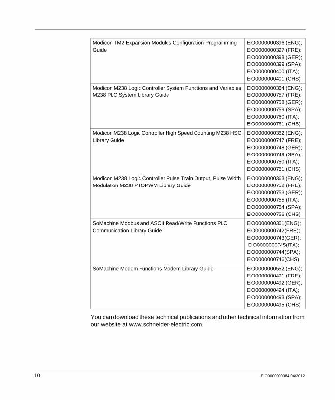
You can download these technical publications and other technical information from our website at www.schneider-electric.com.
Modicon TM2 Expansion Modules Configuration Programming Guide
EIO0000000396 (ENG); EIO0000000397 (FRE); EIO0000000398 (GER); EIO0000000399 (SPA); EIO0000000400 (ITA); EIO0000000401 (CHS)
Modicon M238 Logic Controller System Functions and Variables M238 PLC System Library Guide
EIO0000000364 (ENG); EIO0000000757 (FRE); EIO0000000758 (GER); EIO0000000759 (SPA); EIO0000000760 (ITA); EIO0000000761 (CHS)
Modicon M238 Logic Controller High Speed Counting M238 HSC Library Guide
EIO0000000362 (ENG); EIO0000000747 (FRE); EIO0000000748 (GER); EIO0000000749 (SPA); EIO0000000750 (ITA); EIO0000000751 (CHS)
Modicon M238 Logic Controller Pulse Train Output, Pulse Width Modulation M238 PTOPWM Library Guide
EIO0000000363 (ENG); EIO0000000752 (FRE); EIO0000000753 (GER); EIO0000000755 (ITA); EIO0000000754 (SPA); EIO0000000756 (CHS)
SoMachine Modbus and ASCII Read/Write Functions PLC Communication Library Guide
EIO0000000361(ENG); EIO0000000742(FRE); EIO0000000743(GER); EIO0000000745(ITA); EIO0000000744(SPA); EIO0000000746(CHS)
SoMachine Modem Functions Modem Library Guide EIO0000000552 (ENG); EIO0000000491 (FRE); EIO0000000492 (GER); EIO0000000494 (ITA); EIO0000000493 (SPA); EIO0000000495 (CHS)
10 EIO0000000384 04/2012
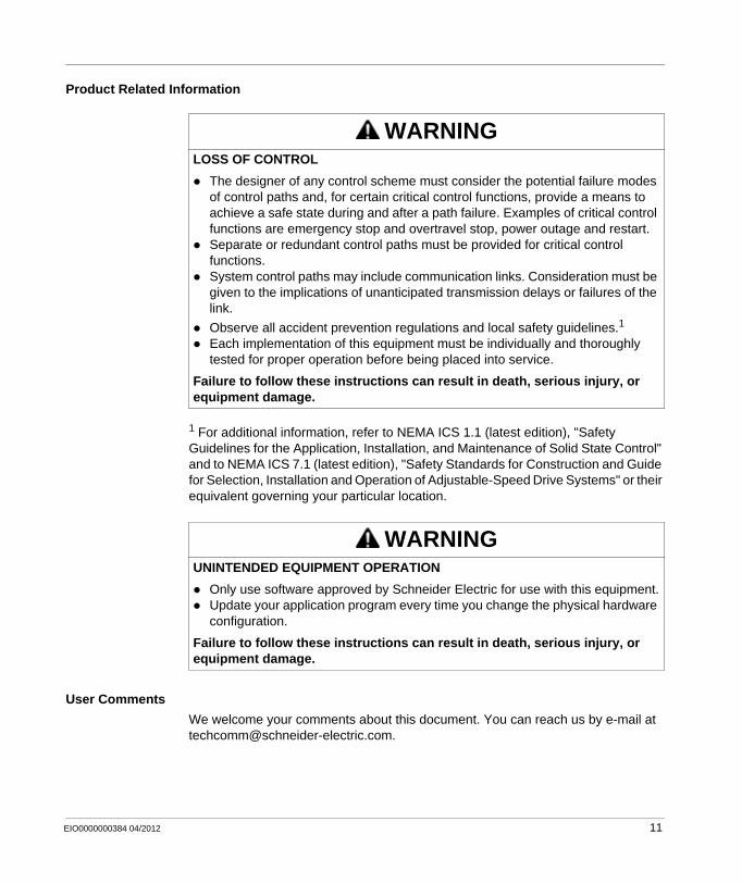
Product Related Information
1 For additional information, refer to NEMA ICS 1.1 (latest edition), "Safety Guidelines for the Application, Installation, and Maintenance of Solid State Control" and to NEMA ICS 7.1 (latest edition), "Safety Standards for Construction and Guide for Selection, Installation and Operation of Adjustable-Speed Drive Systems" or their equivalent governing your particular location.
User Comments
We welcome your comments about this document. You can reach us by e-mail at [email protected].
WARNINGLOSS OF CONTROL
The designer of any control scheme must consider the potential failure modes of control paths and, for certain critical control functions, provide a means to achieve a safe state during and after a path failure. Examples of critical control functions are emergency stop and overtravel stop, power outage and restart.Separate or redundant control paths must be provided for critical control functions.System control paths may include communication links. Consideration must be given to the implications of unanticipated transmission delays or failures of the link.
Observe all accident prevention regulations and local safety guidelines.1
Each implementation of this equipment must be individually and thoroughly tested for proper operation before being placed into service.
Failure to follow these instructions can result in death, serious injury, or equipment damage.
WARNINGUNINTENDED EQUIPMENT OPERATION
Only use software approved by Schneider Electric for use with this equipment.Update your application program every time you change the physical hardware configuration.
Failure to follow these instructions can result in death, serious injury, or equipment damage.
EIO0000000384 04/2012 11

12 EIO0000000384 04/2012
EIO0000000384 04/2012
1
Modicon M238 Logic Controller
M238 - About the Modicon M238 Logic Controller
EIO0000000384 04/2012
About the Modicon M238 Logic Controller
Modicon M238 Logic Controller Devices Overview
Overview
The Schneider Electric Modicon M238 Logic Controller has a variety of powerful features. This controller can service a wide range of applications.
Key Features
The Modicon M238 Logic Controller is supported and programmed with the SoMachine Programming Software, which provides the following IEC61131-3 programming languages:
IL: Instruction ListST: Structured TextFBD: Function Block DiagramSFC: Sequential Function ChartLD: Ladder DiagramCFC: Continuous Function Chart
The Modicon M238 Logic Controller can manage up to 7 tasks (1 MAST task and up to 6 other tasks).
The power supply of Modicon M238 Logic Controller is either:24 Vdc100...240 Vac
The Modicon M238 Logic Controller with DC power supply includes the following features:
14 digital inputs, including 8 fast inputs10 digital outputs, including 4 fast outputs
The Modicon M238 Logic Controller with AC power supply includes the following features:
14 digital inputs, including 8 fast inputs10 digital outputs, including 6 relay outputs
13
M238 - About the Modicon M238 Logic Controller
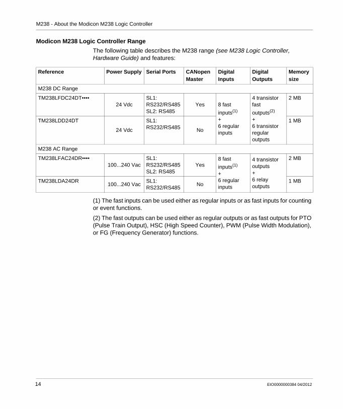
Modicon M238 Logic Controller Range
The following table describes the M238 range (see M238 Logic Controller, Hardware Guide) and features:
(1) The fast inputs can be used either as regular inputs or as fast inputs for counting or event functions.
(2) The fast outputs can be used either as regular outputs or as fast outputs for PTO (Pulse Train Output), HSC (High Speed Counter), PWM (Pulse Width Modulation), or FG (Frequency Generator) functions.
Reference Power Supply Serial Ports CANopen Master
Digital Inputs
Digital Outputs
Memory size
M238 DC Range
TM238LFDC24DT••••24 Vdc
SL1: RS232/RS485SL2: RS485
Yes 8 fast
inputs(1)
+6 regular inputs
4 transistor fast
outputs(2)
+6 transistor regular outputs
2 MB
TM238LDD24DT
24 Vdc
SL1: RS232/RS485 No
1 MB
M238 AC Range
TM238LFAC24DR••••100...240 Vac
SL1: RS232/RS485SL2: RS485
Yes8 fast
inputs(1)
+6 regular inputs
4 transistor outputs+6 relay outputs
2 MB
TM238LDA24DR100...240 Vac
SL1: RS232/RS485
No1 MB
14 EIO0000000384 04/2012
EIO0000000384 04/2012
2
Modicon M238 Logic Controller
How to Configure the Controller
EIO0000000384 04/2012
How to Configure the Controller
How to Configure the Controller
Introduction
Before configuring the controller, you must first create a new project or open an existing project in the SoMachine software (see SoMachine, Programming Guide).
Graphical Configuration Editor
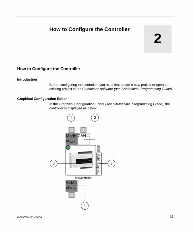
In the Graphical Configuration Editor (see SoMachine, Programming Guide), the controller is displayed as below:
15
How to Configure the Controller
Click on the following element to add (if empty) or replace objects:
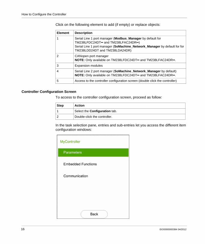
Controller Configuration Screen
To access to the controller configuration screen, proceed as follow:
In the task selection pane, entries and sub-entries let you access the different item configuration windows:
Element Description
1 Serial Line 1 port manager (Modbus_Manager by default for TM238LFDC24DT•• and TM238LFAC24DR••)Serial Line 1 port manager (SoMachine_Network_Manager by default for for TM238LDD24DT and TM238LDA24DR)
2 CANopen port managerNOTE: Only available on TM238LFDC24DT•• and TM238LFAC24DR••.
3 Expansion modules
4 Serial Line 2 port manager (SoMachine_Network_Manager by default)NOTE: Only available on TM238LFDC24DT•• and TM238LFAC24DR••.
5 Access to the controller configuration screen (double click the controller)
Step Action
1 Select the Configuration tab.
2 Double-click the controller.
16 EIO0000000384 04/2012
How to Configure the Controller
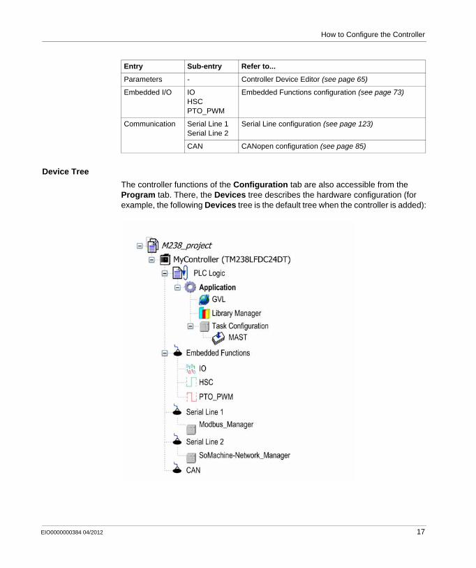
Device Tree
The controller functions of the Configuration tab are also accessible from the Program tab. There, the Devices tree describes the hardware configuration (for example, the following Devices tree is the default tree when the controller is added):
Entry Sub-entry Refer to...
Parameters - Controller Device Editor (see page 65)
Embedded I/O IOHSCPTO_PWM
Embedded Functions configuration (see page 73)
Communication Serial Line 1Serial Line 2
Serial Line configuration (see page 123)
CAN CANopen configuration (see page 85)
EIO0000000384 04/2012 17
How to Configure the Controller
Content of Device Tree
The device tree represents the objects managed by a specific target (controller or HMI). These objects are:
application objects (Tasks, etc.),programming objects (POU, GVL, etc.),hardware-related objects (Embedded functions, CAN, Expansion modules, etc.)
By default, the device tree includes the following hardware-related objects:
Item Description
PLC Logic This part shows everything related to the application:Tasks configurationProgrammingLibrary managerPOUsRelocation Table
Embedded Functions This representation shows the Embedded Functions of the M238.
Serial Line 1Serial Line 2CAN
These are the embedded communications.NOTE: Serial Line 2 and CAN are available only on TM238LFDC24DT•• and TM238LFAC24DR••
Reference Embedded IO Embedded communications
TM238LDD24DTTM238LDA24DR
IOHSCPTO_PWM
Serial Line (SoMachine_Network_Manager)
TM238LFDC24DT••TM238LFAC24DR••
Serial Line 1 (Modbus_Manager)Serial Line 2 (SoMachine_Network_Manager)CAN (CANopen)
18 EIO0000000384 04/2012
EIO0000000384 04/2012
3
Modicon M238 Logic Controller
Libraries
EIO0000000384 04/2012
Libraries
Libraries
Introduction
Libraries provide functions, function blocks, data types and global variables that can be used to develop your project.
The Library Manager of SoMachine provides information about the libraries included in your project and allows you to install new ones. For more information on the Library Manager, refer to the CoDeSys part of the SoMachine online help.
Modicon M238 Logic Controller
When you select a Modicon M238 Logic Controller for your application, SoMachine automatically loads the following libraries:
Library name Description
IoStandard CmpIoMgr configuration types, ConfigAccess, Parameters and help functions: manages the I/Os in the application.
Standard Contains all functions and function blocks which are required matching IEC61131-3 as standard POUs for an IEC programming system. The standard POUs must be tied to the project (standard.library).
Util Analog Monitors, BCD Conversions, Bit/Byte Functions, Controller Datatypes, Function Manipulators, Mathematical Functions, Signals.
M238 PLCSystem (see Modicon M238 Logic Controller, System Functions and Variables, M238 PLCSystem Library Guide)
Contains functions and variables to get information and send commands to the controller system.
19
Libraries
M238 HSC (see Modicon M238 Logic Controller, High Speed Counting, M238 HSC Library Guide)
Contains function blocks and variables to get information and send commands to the Fast Inputs/Outputs of the Modicon M238 Logic Controller. These function blocks permit you to implement HSC (High Speed Counting) functions on the Fast Inputs/Outputs of the Modicon M238 Logic Controller.
M238 PTOPWM (see Modicon M238 Logic Controller, Pulse Train Output, Pulse Width Modulation, M238 PTOPWM Library Guide)
Contains function blocks and variables to get information and send commands to the Fast Inputs/Outputs of the Modicon M238 Logic Controller. These function blocks permit you to implement PTO (Pulse Train Output) and PWM (Pulse With Modulation) functions on the Fast Outputs of the Modicon M238 Logic Controller.
M238 Relocation Table (see page 28)
The relocation table allows the user to organize data to optimize exchanges between the Modbus client and the controller, by regrouping non-contiguous data into a contiguous table of registers.
Library name Description
20 EIO0000000384 04/2012
EIO0000000384 04/2012
4
Modicon M238 Logic Controller
Supported Standard Data Types
EIO0000000384 04/2012
Supported Standard Data Types
Supported Standard Data Types
Supported Standard Data Types
The Controller supports the following IEC Data types:
For more information on ARRAY, LTIME, DATE, TIME, DATE_AND_TIME, and TIME_OF_DAY, refer to the CoDeSys part of the SoMachine online help.
Data type Lower limit Upper limit Information content
BOOL False True 1 Bit
BYTE 0 255 8 Bit
WORD 0 65,535 16 Bit
DWORD 0 4,294,967,295 32 Bit
LWORD 0 264-1 64 Bit
SINT -128 127 8 Bit
USINT 0 255 8 Bit
INT -32,768 32,767 16 Bit
UINT 0 65,535 16 Bit
DINT -2,147,483,648 2,147,483,647 32 Bit
UDINT 0 4,294,967,295 32 Bit
LINT -263 263-1 64 Bit
ULINT 0 264-1 64 Bit
REAL 1.175494351e-38 3.402823466e+38 32 Bit
LREAL 2.2250738585072014e-308 1.7976931348623158e+308 64 Bit
STRING 1 character 255 characters 1 character = 1 byte
WSTRING 1 character 255 characters 1 character = 1 word
TIME - - 16 bit
21

Supported Standard Data Types
22 EIO0000000384 04/2012
EIO0000000384 04/2012
5
Modicon M238 Logic Controller
Memory Mapping
EIO0000000384 04/2012
Memory Mapping
Introduction
This chapter describes the memory maps and sizes of the different memory areas in the Modicon M238 Logic Controller. These memory areas are used to store user program logic, data and the programming libraries.
What’s in this Chapter?
This chapter contains the following topics:
Topic Page
Memory Organization 24
Relocation Table 28
23
Memory Mapping
Memory Organization
Introduction
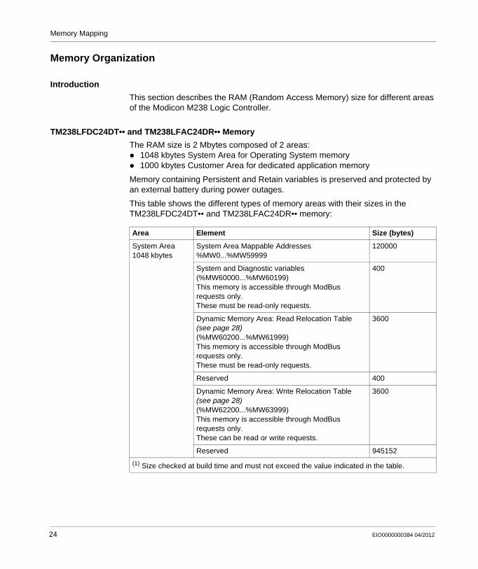
This section describes the RAM (Random Access Memory) size for different areas of the Modicon M238 Logic Controller.
TM238LFDC24DT•• and TM238LFAC24DR•• Memory
The RAM size is 2 Mbytes composed of 2 areas:1048 kbytes System Area for Operating System memory1000 kbytes Customer Area for dedicated application memory
Memory containing Persistent and Retain variables is preserved and protected by an external battery during power outages.
This table shows the different types of memory areas with their sizes in the TM238LFDC24DT•• and TM238LFAC24DR•• memory:
Area Element Size (bytes)
System Area1048 kbytes
System Area Mappable Addresses%MW0...%MW59999
120000
System and Diagnostic variables(%MW60000...%MW60199)This memory is accessible through ModBus requests only.These must be read-only requests.
400
Dynamic Memory Area: Read Relocation Table (see page 28)(%MW60200...%MW61999)This memory is accessible through ModBus requests only.These must be read-only requests.
3600
Reserved 400
Dynamic Memory Area: Write Relocation Table (see page 28) (%MW62200...%MW63999)This memory is accessible through ModBus requests only.These can be read or write requests.
3600
Reserved 945152
(1) Size checked at build time and must not exceed the value indicated in the table.
24 EIO0000000384 04/2012
Memory Mapping
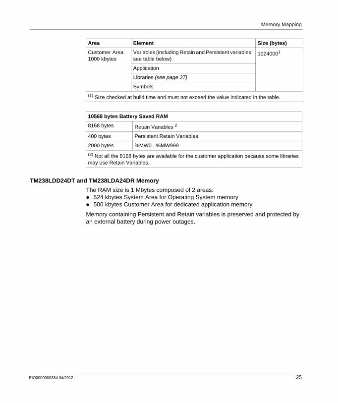
TM238LDD24DT and TM238LDA24DR Memory
The RAM size is 1 Mbytes composed of 2 areas:524 kbytes System Area for Operating System memory500 kbytes Customer Area for dedicated application memory
Memory containing Persistent and Retain variables is preserved and protected by an external battery during power outages.
Customer Area1000 kbytes
Variables (including Retain and Persistent variables, see table below)
10240001
Application
Libraries (see page 27)
Symbols
10568 bytes Battery Saved RAM
8168 bytes Retain Variables 2
400 bytes Persistent Retain Variables
2000 bytes %MW0...%MW999
(2) Not all the 8168 bytes are available for the customer application because some libraries may use Retain Variables.
Area Element Size (bytes)
(1) Size checked at build time and must not exceed the value indicated in the table.
EIO0000000384 04/2012 25
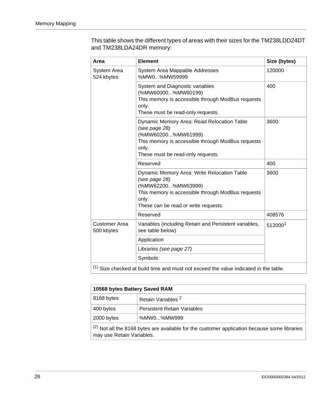
Memory Mapping
This table shows the different types of areas with their sizes for the TM238LDD24DT and TM238LDA24DR memory:
Area Element Size (bytes)
System Area524 kbytes
System Area Mappable Addresses%MW0...%MW59999
120000
System and Diagnostic variables(%MW60000...%MW60199)This memory is accessible through ModBus requests only.These must be read-only requests.
400
Dynamic Memory Area: Read Relocation Table (see page 28)(%MW60200...%MW61999)This memory is accessible through ModBus requests only.These must be read-only requests.
3600
Reserved 400
Dynamic Memory Area: Write Relocation Table (see page 28) (%MW62200...%MW63999)This memory is accessible through ModBus requests only.These can be read or write requests.
3600
Reserved 408576
Customer Area500 kbytes
Variables (including Retain and Persistent variables, see table below)
5120001
Application
Libraries (see page 27)
Symbols
(1) Size checked at build time and must not exceed the value indicated in the table.
10568 bytes Battery Saved RAM
8168 bytes Retain Variables 2
400 bytes Persistent Retain Variables
2000 bytes %MW0...%MW999
(2) Not all the 8168 bytes are available for the customer application because some libraries may use Retain Variables.
26 EIO0000000384 04/2012
Memory Mapping
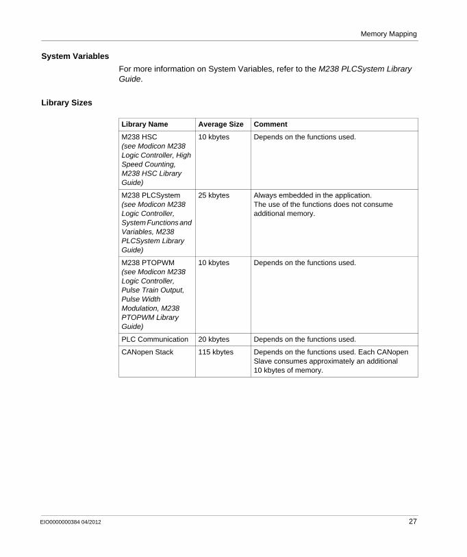
System Variables
For more information on System Variables, refer to the M238 PLCSystem Library Guide.
Library Sizes
Library Name Average Size Comment
M238 HSC (see Modicon M238 Logic Controller, High Speed Counting, M238 HSC Library Guide)
10 kbytes Depends on the functions used.
M238 PLCSystem (see Modicon M238 Logic Controller, System Functions and Variables, M238 PLCSystem Library Guide)
25 kbytes Always embedded in the application.The use of the functions does not consume additional memory.
M238 PTOPWM (see Modicon M238 Logic Controller, Pulse Train Output, Pulse Width Modulation, M238 PTOPWM Library Guide)
10 kbytes Depends on the functions used.
PLC Communication 20 kbytes Depends on the functions used.
CANopen Stack 115 kbytes Depends on the functions used. Each CANopen Slave consumes approximately an additional 10 kbytes of memory.
EIO0000000384 04/2012 27
Memory Mapping
Relocation Table
Introduction
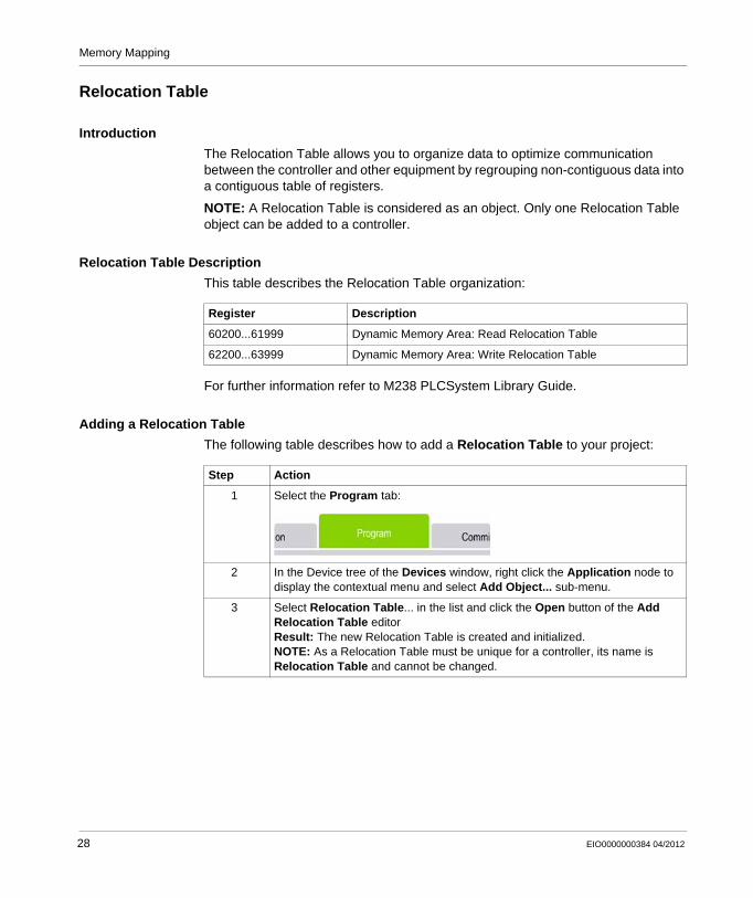
The Relocation Table allows you to organize data to optimize communication between the controller and other equipment by regrouping non-contiguous data into a contiguous table of registers.
NOTE: A Relocation Table is considered as an object. Only one Relocation Table object can be added to a controller.
Relocation Table Description
This table describes the Relocation Table organization:
For further information refer to M238 PLCSystem Library Guide.
Adding a Relocation Table
The following table describes how to add a Relocation Table to your project:
Register Description
60200...61999 Dynamic Memory Area: Read Relocation Table
62200...63999 Dynamic Memory Area: Write Relocation Table
Step Action
1 Select the Program tab:
2 In the Device tree of the Devices window, right click the Application node to display the contextual menu and select Add Object... sub-menu.
3 Select Relocation Table... in the list and click the Open button of the Add Relocation Table editorResult: The new Relocation Table is created and initialized.NOTE: As a Relocation Table must be unique for a controller, its name is Relocation Table and cannot be changed.
28 EIO0000000384 04/2012
Memory Mapping
Relocation Table Editor
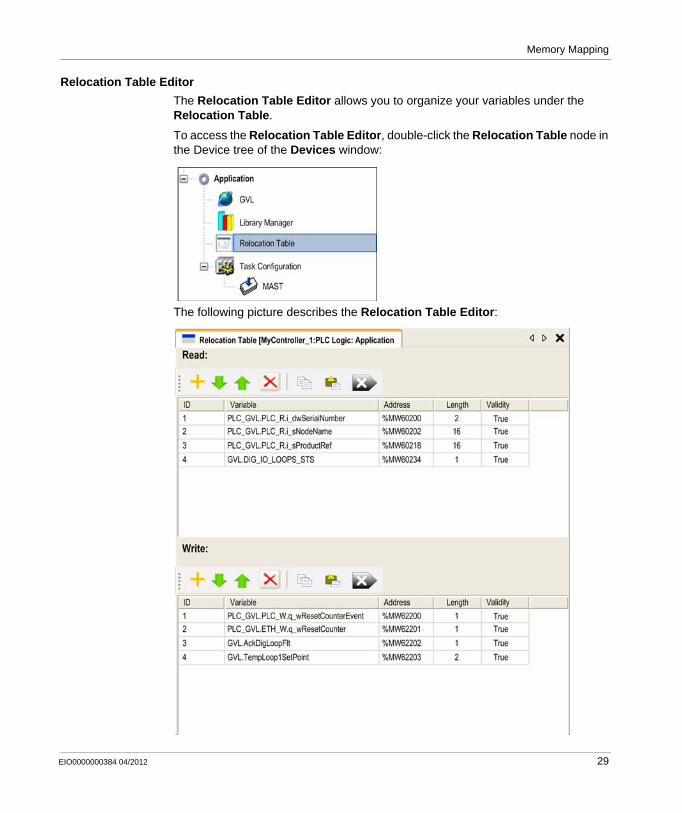
The Relocation Table Editor allows you to organize your variables under the Relocation Table.
To access the Relocation Table Editor, double-click the Relocation Table node in the Device tree of the Devices window:
The following picture describes the Relocation Table Editor:
EIO0000000384 04/2012 29
Memory Mapping
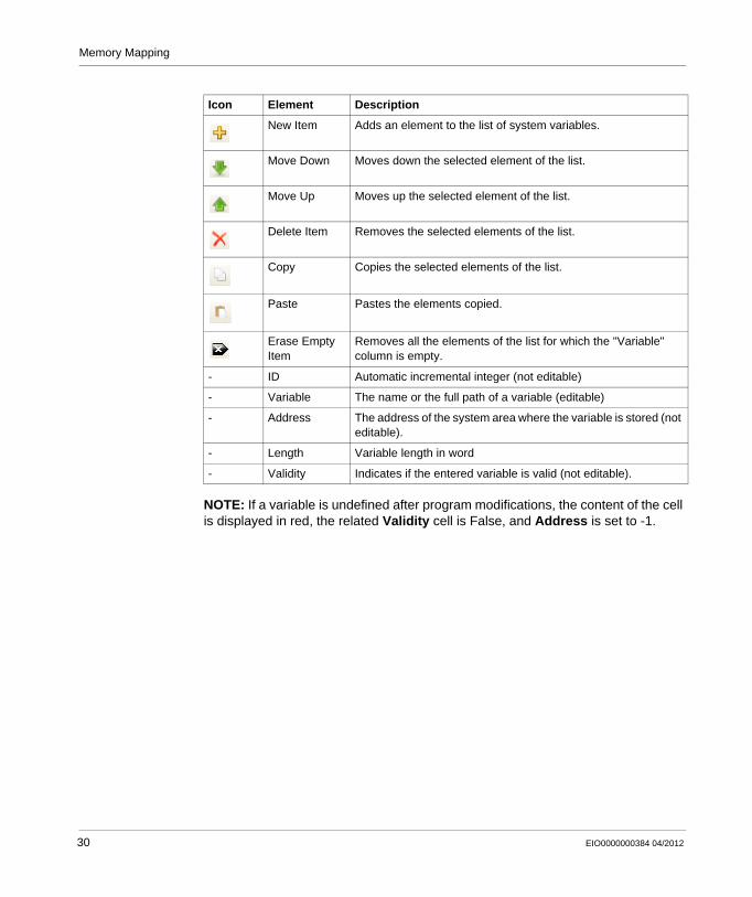
NOTE: If a variable is undefined after program modifications, the content of the cell is displayed in red, the related Validity cell is False, and Address is set to -1.
Icon Element Description
New Item Adds an element to the list of system variables.
Move Down Moves down the selected element of the list.
Move Up Moves up the selected element of the list.
Delete Item Removes the selected elements of the list.
Copy Copies the selected elements of the list.
Paste Pastes the elements copied.
Erase Empty Item
Removes all the elements of the list for which the "Variable" column is empty.
- ID Automatic incremental integer (not editable)
- Variable The name or the full path of a variable (editable)
- Address The address of the system area where the variable is stored (not editable).
- Length Variable length in word
- Validity Indicates if the entered variable is valid (not editable).
30 EIO0000000384 04/2012
EIO0000000384 04/2012
6
Modicon M238 Logic Controller
Tasks
EIO0000000384 04/2012
Tasks
Introduction
The Task Configuration node in the SoMachine device tree allows you to define one or several tasks to control the execution of your application program.
The task types available are:CyclicFreewheelingEventExternal Event
This chapter begins with an explanation of these task types and provides information regarding the maximum number of tasks, the default task configuration, and task prioritization. In addition, this chapter introduces the system and task watchdog functions and explains their relationship to task execution.
What’s in this Chapter?
This chapter contains the following topics:
Topic Page
Maximum Number of Tasks 32
Task Configuration Screen 33
Task Types 35
System and Task Watchdogs 38
Task Priorities 39
Default Task Configuration 41
31
Tasks
Maximum Number of Tasks
Maximum Number of Tasks
The maximum number of tasks you can define for the Modicon M238 Logic Controller are:
Total number of tasks = 7Cyclic tasks = 3Freewheeling tasks = 1Event tasks = 2External Event tasks = 4
NOTE: The total number of Freewheeling task, Cyclic tasks and Event tasks must not be greater than 3.
Special Considerations for Freewheeling
A Freewheeling task (see page 36) does not have a fixed duration. In Freewheeling mode, each task scan starts when the previous scan has been completed and after a period of system processing (30% of the total duration of the Freewheeling task). If the system processing period is reduced to less than 15% for more than 3 seconds due to other tasks interruptions, a system error is detected. For more information refer to the System Watchdog (see page 38).
It is recommended not to use a Freewheeling task in a multi-tasks application when some high priority and time-consuming tasks are running.
32 EIO0000000384 04/2012
Tasks
Task Configuration Screen
Screen Description
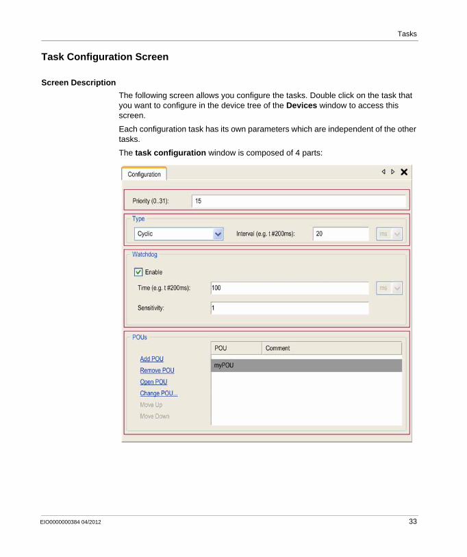
The following screen allows you configure the tasks. Double click on the task that you want to configure in the device tree of the Devices window to access this screen.
Each configuration task has its own parameters which are independent of the other tasks.
The task configuration window is composed of 4 parts:
EIO0000000384 04/2012 33
Tasks
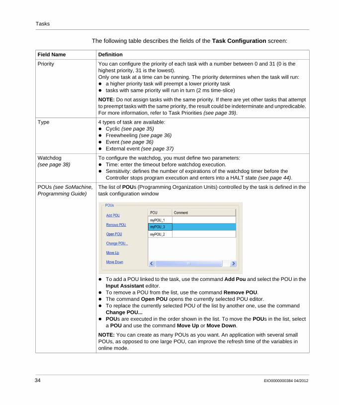
The following table describes the fields of the Task Configuration screen:
Field Name Definition
Priority You can configure the priority of each task with a number between 0 and 31 (0 is the highest priority, 31 is the lowest).Only one task at a time can be running. The priority determines when the task will run:
a higher priority task will preempt a lower priority tasktasks with same priority will run in turn (2 ms time-slice)
NOTE: Do not assign tasks with the same priority. If there are yet other tasks that attempt to preempt tasks with the same priority, the result could be indeterminate and unpredicable. For more information, refer to Task Priorities (see page 39).
Type 4 types of task are available:Cyclic (see page 35)Freewheeling (see page 36)Event (see page 36)External event (see page 37)
Watchdog (see page 38)
To configure the watchdog, you must define two parameters:Time: enter the timeout before watchdog execution.Sensitivity: defines the number of expirations of the watchdog timer before the Controller stops program execution and enters into a HALT state (see page 44).
POUs (see SoMachine, Programming Guide)
The list of POUs (Programming Organization Units) controlled by the task is defined in the task configuration window
To add a POU linked to the task, use the command Add Pou and select the POU in the Input Assistant editor.To remove a POU from the list, use the command Remove POU.The command Open POU opens the currently selected POU editor.To replace the currently selected POU of the list by another one, use the command Change POU...POUs are executed in the order shown in the list. To move the POUs in the list, select a POU and use the command Move Up or Move Down.
NOTE: You can create as many POUs as you want. An application with several small POUs, as opposed to one large POU, can improve the refresh time of the variables in online mode.
34 EIO0000000384 04/2012
Tasks
Task Types
Introduction
The following section describes the various task types available for your program, along with a description of the task type characteristics.
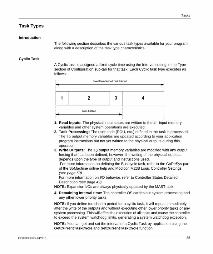
Cyclic Task
A Cyclic task is assigned a fixed cycle time using the Interval setting in the Type section of Configuration sub-tab for that task. Each Cyclic task type executes as follows:
1. Read Inputs: The physical input states are written to the %I input memory variables and other system operations are executed.
2. Task Processing: The user code (POU, etc.) defined in the task is processed. The %Q output memory variables are updated according to your application program instructions but not yet written to the physical outputs during this operation.
3. Write Outputs: The %Q output memory variables are modified with any output forcing that has been defined; however, the writing of the physical outputs depends upon the type of output and instructions used. For more information on defining the Bus cycle task, refer to the CoDeSys part of the SoMachine online help and Modicon M238 Logic Controller Settings (see page 69).For more information on I/O behavior, refer to Controller States Detailed Description (see page 49).
NOTE: Expansion I/Os are always physically updated by the MAST task.
4. Remaining Interval time: The controller OS carries out system processing and any other lower priority tasks.
NOTE: If you define too short a period for a cyclic task, it will repeat immediately after the write of the outputs and without executing other lower priority tasks or any system processing. This will affect the execution of all tasks and cause the controller to exceed the system watchdog limits, generating a system watchdog exception.
NOTE: You can get and set the interval of a Cyclic Task by application using the GetCurrentTaskCycle and SetCurrentTaskCycle function.
EIO0000000384 04/2012 35
Tasks
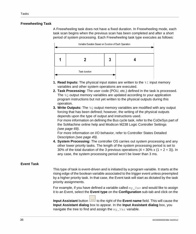
Freewheeling Task
A Freewheeling task does not have a fixed duration. In Freewheeling mode, each task scan begins when the previous scan has been completed and after a short period of system processing. Each Freewheeling task type executes as follows:
1. Read Inputs: The physical input states are written to the %I input memory variables and other system operations are executed.
2. Task Processing: The user code (POU, etc.) defined in the task is processed. The %Q output memory variables are updated according to your application program instructions but not yet written to the physical outputs during this operation.
3. Write Outputs: The %Q output memory variables are modified with any output forcing that has been defined; however, the writing of the physical outputs depends upon the type of output and instructions used.For more information on defining the Bus cycle task, refer to the CoDeSys part of the SoMachine online help and Modicon M238 Logic Controller Settings (see page 69).For more information on I/O behavior, refer to Controller States Detailed Description (see page 49).
4. System Processing: The controller OS carries out system processing and any other lower priority tasks. The length of the system processing period is set to 30% of the total duration of the 3 previous operations (4 = 30% x (1 + 2 + 3)). In any case, the system processing period won’t be lower than 3 ms.
Event Task
This type of task is event-driven and is initiated by a program variable. It starts at the rising edge of the boolean variable associated to the trigger event unless preempted by a higher priority task. In that case, the Event task will start as dictated by the task priority assignments.
For example, if you have defined a variable called my_Var and would like to assign it to an Event, select the Event type on the Configuration sub-tab and click on the
Input Assistant button to the right of the Event name field. This will cause the Input Assistant dialog box to appear. In the Input Assistant dialog box, you navigate the tree to find and assign the my_Var variable.
36 EIO0000000384 04/2012
Tasks
External Event Task
This type of task is event-driven and is initiated by the detection of a hardware or hardware-related function event. It starts when the event occurs unless preempted by a higher priority task. In that case, the External Event task will start as dictated by the task priority assignments.
For example, an External Event task could be associated with an HSC Threshold cross event. To associate the HSC4_TH3 event to an External Event task, select it from the External event dropdown list on the Configuration sub-tab.
Depending on the related product, there are up to 2 types of events that can be associated with an External Event task:
Rising edge on Fast input (%IX0.0 ... %IX0.7 inputs)HSC thresholds
EIO0000000384 04/2012 37
Tasks
System and Task Watchdogs
Introduction
2 types of watchdog functionality are implemented for the Modicon M238 Logic Controller:
System Watchdogs: These watchdogs are defined in and managed by the controller OS (firmware). These are not configurable by the user.Task Watchdogs: Optional watchdogs that can be defined for each task. These are managed by your application program and are configurable in SoMachine.
System Watchdogs
2 system watchdogs are defined for the Modicon M238 Logic Controller. They are managed by the controller OS (firmware) and are therefore sometimes referred to as hardware watchdogs in the SoMachine online help. When one of the system watchdogs exceeds its threshold conditions, an error is detected.
The threshold conditions for the 2 system watchdogs are defined as follows:If all of the tasks require more than 80% of the processor resources for more than 3 seconds, a system error is detected. The controller enters the EMPTY state.If the lowest priority task of the system is not executed during an interval of 20 seconds, a system error is detected. The controller responds with an automatic reboot into the EMPTY state.
NOTE: System watchdogs are not configurable by the user.
Task Watchdogs
SoMachine allows you to configure an optional task watchdog for every task defined in your application program. (Task watchdogs are sometimes also referred to as software watchdogs or control timers in the SoMachine online help). When one of your defined task watchdogs reaches its threshold condition, an application error is detected and the controller enters the HALT state.
When defining a task watchdog, the following options are available:Time: This defines the allowable maximum execution time for a task. When a task takes longer than this the controller will report a task watchdog exception.Sensitivity: The sensitivity field defines the number of task watchdog exceptions that must occur before the controller detects an application error.
A task watchdog is configured on the Configuration sub-tab of the Task Configuration tab for the individual task. To access this tab, double-click the task in the device tree.
NOTE: For more information on watchdogs, refer to the CoDeSys part of the SoMachine online help.
38 EIO0000000384 04/2012
Tasks
Task Priorities
Introduction
You can configure the priority of each task between 0 and 31 (0 is the highest priority, 31 is the lowest). Each task must have a unique priority. If you assign the same priority to more than one task, execution for those tasks is indeterminate and unpredictable, which may lead to unintended consequences.
WARNINGUNINTENDED EQUIPMENT OPERATION
Do not assign the same priority to different tasks.
Failure to follow these instructions can result in death, serious injury, or equipment damage.
EIO0000000384 04/2012 39
Tasks
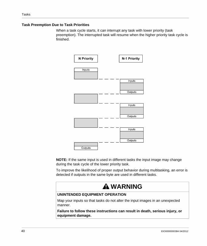
Task Preemption Due to Task Priorities
When a task cycle starts, it can interrupt any task with lower priority (task preemption). The interrupted task will resume when the higher priority task cycle is finished.
NOTE: If the same input is used in different tasks the input image may change during the task cycle of the lower priority task.
To improve the likelihood of proper output behavior during multitasking, an error is detected if outputs in the same byte are used in different tasks.
WARNINGUNINTENDED EQUIPMENT OPERATION
Map your inputs so that tasks do not alter the input images in an unexpected manner.
Failure to follow these instructions can result in death, serious injury, or equipment damage.
40 EIO0000000384 04/2012
Tasks
Default Task Configuration
Default Task Configuration
For the Modicon M238 Logic Controller:The MAST task can be configured in Freewheeling or Cyclic mode. The MAST task is automatically created by default in Cyclic mode. Its preset priority is medium (15), its preset interval is 20 ms, and its task watchdog service is activated with a time of 100 ms and a sensitivity of 1. Refer to Task Priorities (see page 39) for more information on priority settings. Refer to System and Task Watchdogs (see page 38) for more information on watchdogs.
Designing an efficient application program is important in systems approaching the maximum number of tasks. In such an application, it can be difficult to keep the resource utilization below the system watchdog threshold. If priority reassignments alone are not sufficient to remain below the threshold, some lower priority tasks can be made to use fewer system resources if the SysTaskWaitSleep function is added to those tasks. For more information about this function, see the optional SysTask library of the system / SysLibs category of libraries.
NOTE: Do not delete or change the Name of the MAST task. If you do so, SoMachine detects an error when you attempt to build the application, and you will not be able to download it to the controller.
EIO0000000384 04/2012 41

Tasks
42 EIO0000000384 04/2012
EIO0000000384 04/2012
7
Modicon M238 Logic Controller
Controller States and Behaviors
EIO0000000384 04/2012
Controller States and Behaviors
Introduction
This chapter provides you with information on controller states, state transitions, and behaviors in response to system events. It begins with a detailed controller state diagram and a description of each state. It then defines the relationship of output states to controller states before explaining the commands and events that result in state transitions. It concludes with information about Remanent variables and the effect of SoMachine task programming options on the behavior of your system.
What’s in this Chapter?
This chapter contains the following sections:
Section Topic Page
7.1 Controller State Diagram 44
7.2 Controller States Description 49
7.3 State Transitions and System Events 53
43
Controller States and Behaviors
7.1 Controller State Diagram
Controller State Diagram
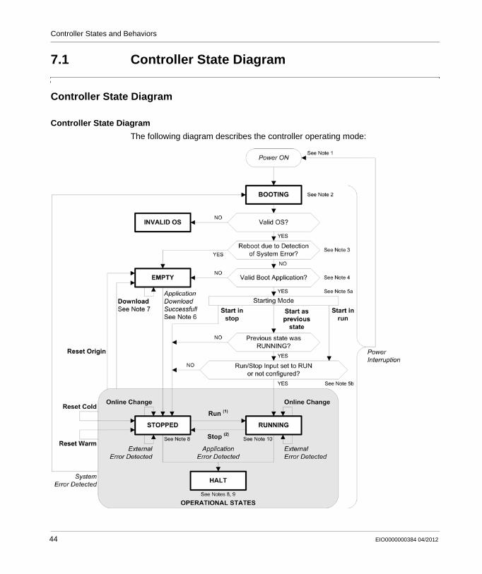
Controller State Diagram
The following diagram describes the controller operating mode:
44 EIO0000000384 04/2012
Controller States and Behaviors
Legend:Controller states are indicated in ALL-CAPS BOLDUser and application commands are indicated in BoldSystem events are indicated in ItalicsDecisions, decision results and general information are indicated in normal text
(1) For details on STOPPED to RUNNING state transition, refer to Run Command (see page 57).
(2) For details on RUNNING to STOPPED state transition, refer to Stop Command (see page 57).
Note 1
The Power Cycle (Power Interruption followed by a Power ON) deletes all output forcing settings. Refer to Controller State and Output Behavior (see page 54) for further details.
Note 2
The boot process can take up to 10 seconds under normal conditions. The outputs will assume their initialization states.
Note 3
In some cases, when a system error is detected, it will cause the controller to automatically reboot into the EMPTY state as if no Boot application were present in the Flash memory. However, the Boot application is not actually deleted from the Flash memory.
Note 4
The application is loaded into RAM after verification of a valid Boot application.
During the load of the boot application, a Check context test occurs to assure that the Remanent variables are valid. If this test fails the boot application will load but the controller will assume STOPPED state (see page 60).
Note 5a
The Starting Mode is set in the PLC settings tab of the Controller Device Editor (see page 69) .
EIO0000000384 04/2012 45
Controller States and Behaviors
Note 5b
When a power interruption occurs, the controller continues in the RUNNING state for at least 4 ms before shutting down. If you have configured and provide power to the Run/Stop input from the same source as the controller, the loss of power to this input will be detected immediately, and the controller will behave as if a STOP command was received. Therefore, if you provide power to the controller and the Run/Stop input from the same source, your controller will normally reboot into the STOPPED state after a power interruption when Starting Mode is set to Start as previous state.
Note 6
During a successful application download the following events occur:The application is loaded directly into RAM.By default, the Boot application is created and saved into the Flash memory.
Note 7
The default behavior after downloading an application program is for the controller to enter the STOPPED state irrespective of the Run/Stop input setting or the last controller state before the download.
However, there are two important considerations in this regard:Online Change: An online change (partial download) initiated while the controller
is in the RUNNING state returns the controller to the RUNNING state if successful and provided the Run/Stop input is configured and set to Run. Before using the Login with online change option, test the changes to your application program in a virtual or non-production environment and confirm that the controller and attached equipment assume their expected conditions in the RUNNING state.
NOTE: Online changes to your program are not automatically written to the Boot application, and will be overwritten by the existing Boot application at the next reboot. If you wish your changes to persist through a reboot, manually update the Boot application by selecting Create boot application in the Online menu (the controller must be in the STOPPED state to achieve this operation).
WARNINGUNINTENDED EQUIPMENT OPERATION
Always verify that online changes to a RUNNING application program operate as expected before downloading them to controllers.
Failure to follow these instructions can result in death, serious injury, or equipment damage.
46 EIO0000000384 04/2012
Controller States and Behaviors
Multiple Download: SoMachine has a feature that allows you to perform a full application download to multiple targets on your network or fieldbus. One of the default options when you select the Multiple Download... command is the Start all applications after download or online change option, which restarts all download targets in the RUNNING state, provided their respective Run/Stop inputs are commanding the RUNNING state, but irrespective of their last controller state before the multiple download was initiated. Deselect this option if you do not want all targeted controllers to restart in the RUNNING state. In addition, before using the Multiple Download option, test the changes to your application program in a virtual or non-production environment and confirm that the targeted controllers and attached equipment assume their expected conditions in the RUNNING state.
NOTE: During a multiple download, unlike a normal download, SoMachine does not offer the option to create a Boot application. You can manually create a Boot application at any time by selecting Create boot application in the Online menu on all targeted controllers (the controller must be in the STOPPED state for this operation).
Note 8
The SoMachine software platform allows many powerful options for managing task execution and output conditions while the controller is in the STOPPED or HALT states. Refer to Controller States Description (see page 49) for further details.
Note 9
To exit the HALT state it is necessary to issue one of the Reset commands (Reset Warm, Reset Cold, Reset Origin), download an application or cycle power.
WARNINGUNINTENDED EQUIPMENT OPERATION
Always verify that your application program will operate as expected for all targeted controllers and equipment before issuing the "Multiple Download…" command with the "Start all applications after download or online change" option selected.
Failure to follow these instructions can result in death, serious injury, or equipment damage.
EIO0000000384 04/2012 47
Controller States and Behaviors
Note 10
The RUNNING state has two exception conditions.
They are:RUNNING with External Error: this exception condition is indicated by the Err Status LED, which displays 1 red flash. You may exit this state by clearing the external error. No controller commands are required.RUNNING with Breakpoint: this exception condition is indicated by the RUN Status LED, which displays 1 green flash. Refer to Controller States Description (see page 49) for further details.
48 EIO0000000384 04/2012
Controller States and Behaviors
7.2 Controller States Description
Controller States Description
Introduction
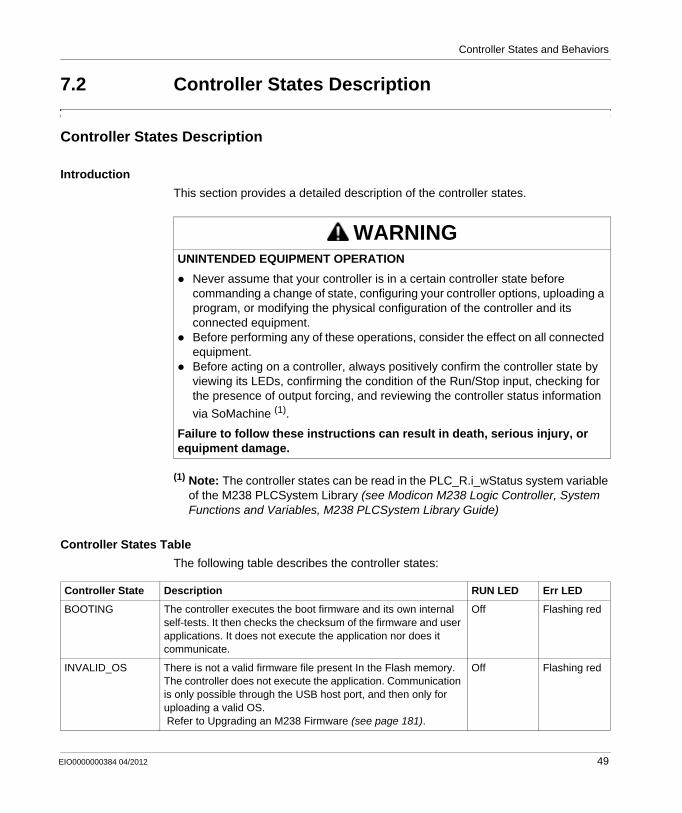
This section provides a detailed description of the controller states.
(1) Note: The controller states can be read in the PLC_R.i_wStatus system variable of the M238 PLCSystem Library (see Modicon M238 Logic Controller, System Functions and Variables, M238 PLCSystem Library Guide)
Controller States Table
The following table describes the controller states:
WARNINGUNINTENDED EQUIPMENT OPERATION
Never assume that your controller is in a certain controller state before commanding a change of state, configuring your controller options, uploading a program, or modifying the physical configuration of the controller and its connected equipment.Before performing any of these operations, consider the effect on all connected equipment.Before acting on a controller, always positively confirm the controller state by viewing its LEDs, confirming the condition of the Run/Stop input, checking for the presence of output forcing, and reviewing the controller status information
via SoMachine (1).
Failure to follow these instructions can result in death, serious injury, or equipment damage.
Controller State Description RUN LED Err LED
BOOTING The controller executes the boot firmware and its own internal self-tests. It then checks the checksum of the firmware and user applications. It does not execute the application nor does it communicate.
Off Flashing red
INVALID_OS There is not a valid firmware file present In the Flash memory. The controller does not execute the application. Communication is only possible through the USB host port, and then only for uploading a valid OS. Refer to Upgrading an M238 Firmware (see page 181).
Off Flashing red
EIO0000000384 04/2012 49
Controller States and Behaviors
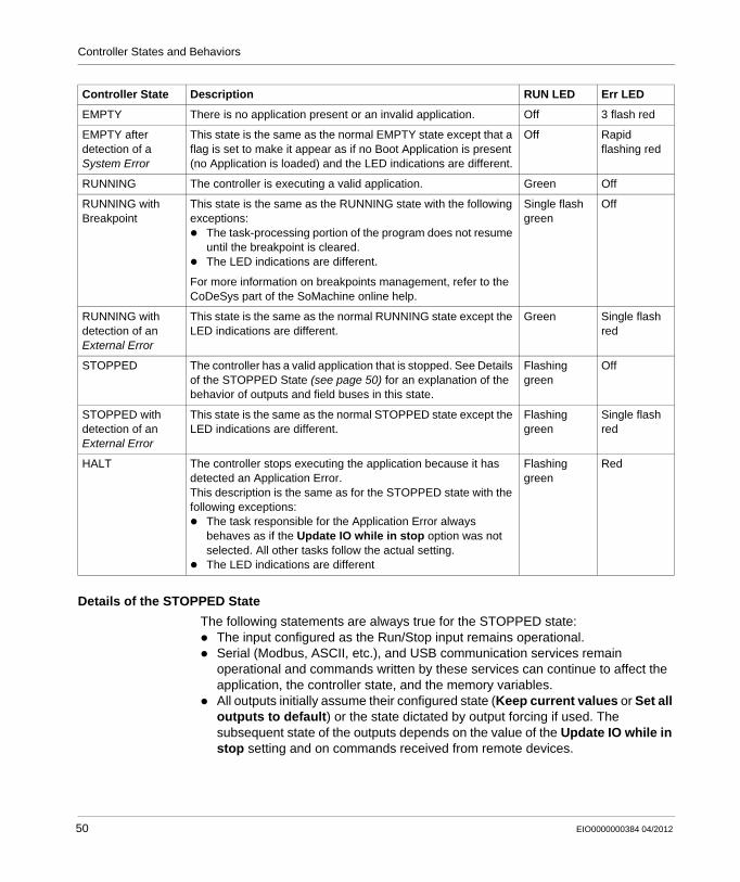
Details of the STOPPED State
The following statements are always true for the STOPPED state:The input configured as the Run/Stop input remains operational.Serial (Modbus, ASCII, etc.), and USB communication services remain operational and commands written by these services can continue to affect the application, the controller state, and the memory variables.All outputs initially assume their configured state (Keep current values or Set all outputs to default) or the state dictated by output forcing if used. The subsequent state of the outputs depends on the value of the Update IO while in stop setting and on commands received from remote devices.
EMPTY There is no application present or an invalid application. Off 3 flash red
EMPTY after detection of a System Error
This state is the same as the normal EMPTY state except that a flag is set to make it appear as if no Boot Application is present (no Application is loaded) and the LED indications are different.
Off Rapid flashing red
RUNNING The controller is executing a valid application. Green Off
RUNNING with Breakpoint
This state is the same as the RUNNING state with the following exceptions:
The task-processing portion of the program does not resume until the breakpoint is cleared.The LED indications are different.
For more information on breakpoints management, refer to the CoDeSys part of the SoMachine online help.
Single flash green
Off
RUNNING with detection of an External Error
This state is the same as the normal RUNNING state except the LED indications are different.
Green Single flash red
STOPPED The controller has a valid application that is stopped. See Details of the STOPPED State (see page 50) for an explanation of the behavior of outputs and field buses in this state.
Flashing green
Off
STOPPED with detection of an External Error
This state is the same as the normal STOPPED state except the LED indications are different.
Flashing green
Single flash red
HALT The controller stops executing the application because it has detected an Application Error.This description is the same as for the STOPPED state with the following exceptions:
The task responsible for the Application Error always behaves as if the Update IO while in stop option was not selected. All other tasks follow the actual setting.The LED indications are different
Flashing green
Red
Controller State Description RUN LED Err LED
50 EIO0000000384 04/2012
Controller States and Behaviors
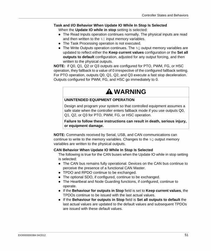
Task and I/O Behavior When Update IO While In Stop Is Selected When the Update IO while in stop setting is selected:
The Read Inputs operation continues normally. The physical inputs are read and then written to the %I input memory variables.The Task Processing operation is not executed.The Write Outputs operation continues. The %Q output memory variables are updated to reflect either the Keep current values configuration or the Set all outputs to default configuration, adjusted for any output forcing, and then written to the physical outputs.
NOTE: if Q0, Q1, Q2 or Q3 outputs are configured for PTO, PWM, FG, or HSC operation, they fallback to a value of 0 irrespective of the configured fallback setting. For PTO operation, outputs Q0, Q1, Q2, and Q3 execute a fast stop deceleration. Outputs configured for PWM, FG, and HSC go immediately to 0.
NOTE: Commands received by Serial, USB, and CAN communications can continue to write to the memory variables. Changes to the %Q output memory variables are written to the physical outputs.
CAN Behavior When Update IO While In Stop Is Selected The following is true for the CAN buses when the Update IO while in stop setting is selected:
The CAN bus remains fully operational. Devices on the CAN bus continue to perceive the presence of a functional CAN Master.TPDO and RPDO continue to be exchanged.The optional SDO, if configured, continue to be exchanged.The Heartbeat and Node Guarding functions, if configured, continue to operate.If the Behaviour for outputs in Stop field is set to Keep current values, the TPDOs continue to be issued with the last actual values.If the Behaviour for outputs in Stop field is Set all outputs to default the last actual values are updated to the default values and subsequent TPDOs are issued with these default values.
WARNINGUNINTENDED EQUIPMENT OPERATION
Design and program your system so that controlled equipment assumes a safe state when the controller enters fallback mode if you use outputs Q0, Q1, Q2, or Q3 for PTO, PWM, FG, or HSC operation.
Failure to follow these instructions can result in death, serious injury, or equipment damage.
EIO0000000384 04/2012 51
Controller States and Behaviors
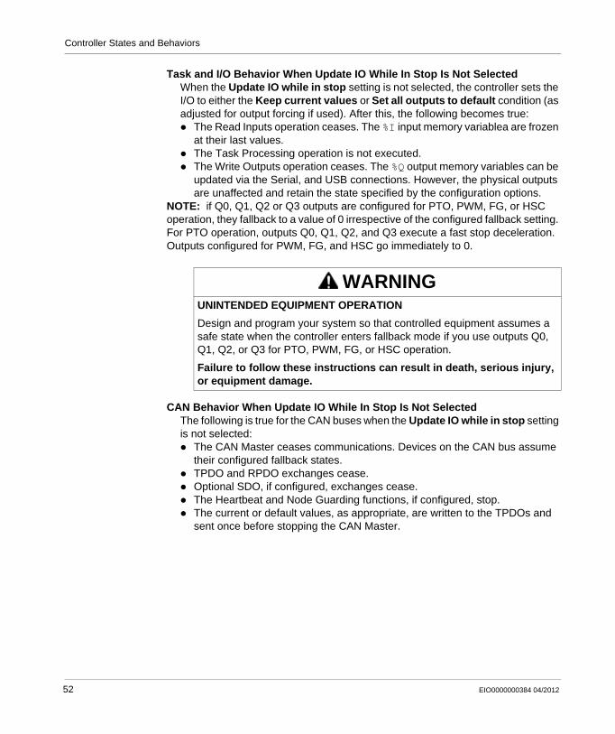
Task and I/O Behavior When Update IO While In Stop Is Not Selected When the Update IO while in stop setting is not selected, the controller sets the I/O to either the Keep current values or Set all outputs to default condition (as adjusted for output forcing if used). After this, the following becomes true:
The Read Inputs operation ceases. The %I input memory variablea are frozen at their last values.The Task Processing operation is not executed.The Write Outputs operation ceases. The %Q output memory variables can be updated via the Serial, and USB connections. However, the physical outputs are unaffected and retain the state specified by the configuration options.
NOTE: if Q0, Q1, Q2 or Q3 outputs are configured for PTO, PWM, FG, or HSC operation, they fallback to a value of 0 irrespective of the configured fallback setting. For PTO operation, outputs Q0, Q1, Q2, and Q3 execute a fast stop deceleration. Outputs configured for PWM, FG, and HSC go immediately to 0.
CAN Behavior When Update IO While In Stop Is Not Selected The following is true for the CAN buses when the Update IO while in stop setting is not selected:
The CAN Master ceases communications. Devices on the CAN bus assume their configured fallback states.TPDO and RPDO exchanges cease.Optional SDO, if configured, exchanges cease.The Heartbeat and Node Guarding functions, if configured, stop.The current or default values, as appropriate, are written to the TPDOs and sent once before stopping the CAN Master.
WARNINGUNINTENDED EQUIPMENT OPERATION
Design and program your system so that controlled equipment assumes a safe state when the controller enters fallback mode if you use outputs Q0, Q1, Q2, or Q3 for PTO, PWM, FG, or HSC operation.
Failure to follow these instructions can result in death, serious injury, or equipment damage.
52 EIO0000000384 04/2012
Controller States and Behaviors
7.3 State Transitions and System Events
Overview
This section begins with an explanation of the output states possible for the controller. It then presents the system commands used to transition between controller states and the system events that can also affect these states. It concludes with an explanation of the Remanent variables, and the circumstances under which different variables and data types are retained through state transitions.
What’s in this Section?
This section contains the following topics:
Topic Page
Controller States and Output Behavior 54
Commanding State Transitions 57
Error Detection, Types, and Management 63
Remanent Variables 64
EIO0000000384 04/2012 53
Controller States and Behaviors
Controller States and Output Behavior
Introduction
The Modicon M238 Logic Controller defines output behavior in response to commands and system events in a way that allows for greater flexibility. An understanding of this behavior is necessary before discussing the commands and events that affect controller states. For example, typical controllers define only two options for output behavior in stop: fallback to default value or keep current value.
The possible output behaviors and the controller states to which they apply are:Managed by Application ProgramKeep Current ValuesSet All Outputs to DefaultInitialization ValuesOutput Forcing
Managed by Application Program
Your application program manages outputs normally. This applies in the RUNNING and RUNNING with External Error states.
Keep Current Values
You can select this option by choosing Keep current values in the Behaviour for outputs in Stop dropdown menu of the PLC settings sub-tab of the Controller Editor. To access the Controller Editor, right-click on the controller in the device tree and select Edit Object.
This output behavior applies in the STOPPED and HALT controller states. Outputs are set to and maintained in their current state, although the details of the output behavior varies greatly depending on the setting of the Update IO while in stop option and the actions commanded via configured fieldbuses. Refer to Controller States Description (see page 49) for more details on these variations.
Set All Outputs to Default
You can select this option by choosing Set all outputs to default in the Behaviour for outputs in Stop dropdown menu of the PLC settings sub-tab of the Controller Editor. To access the Controller Editor, right-click on the controller in the device tree and select Edit Object.
This output behavior applies in the STOPPED and HALT controller states. Outputs are set to and maintained in their current state, although the details of the output behavior varies greatly depending on the setting of the Update IO while in stop option and the actions commanded via configured fieldbuses. Refer to Controller States Description (see page 49) for more details on these variations.
54 EIO0000000384 04/2012
Controller States and Behaviors
Initialization Values
This output state applies in the BOOTING, EMPTY (following power cycle with no boot application or after the detection of a system error), and INVALID_OS states.
In the initialization state, analog, transistor and relay outputs assume the following values:
For an analog output : Z (High Impedance)For a fast transistor output: Z (High Impedance)For a regular transistor output: 0 VdcFor a relay output: Open
Output Forcing
The controller allows you to force the state of selected outputs to a defined value for the purposes of system testing, commissioning and maintenance.
You are only able to force the value of an output while your controller is connected to SoMachine.
To do so you use the Force Values command in the Debug/Watch menu.
Output forcing overrides all other commands to an output irrespective of the task programming that is being executed.
When you logout of SoMachine when output forcing has been defined, you are presented with the option to retain output forcing settings. If you select this option, the output forcing continues to control the state of the selected outputs until you download an application or use one of the Reset commands.
When the option Update IO while in stop, if supported by your controller, is checked (default state), the forced outputs keep the forcing value even when the logic controller is in STOP.
Output Forcing Considerations
The output you wish to force must be contained in a task that is currently being executed by the controller. Forcing outputs in unexecuted tasks, or in tasks whose execution is delayed either by priorities or events will have no effect on the output. However, once the task that had been delayed is executed, the forcing will take effect at that time.
Depending on task execution, the forcing could impact your application in ways that may not be obvious to you. For example, an event task could turn on an output. Later, you may attempt to turn off that output but the event is not being triggered at the time. This would have the effect of the forcing apparently being ignored. Further, at a later time, the event could trigger the task at which point the forcing would take effect.
EIO0000000384 04/2012 55
Controller States and Behaviors
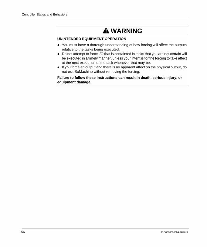
WARNINGUNINTENDED EQUIPMENT OPERATION
You must have a thorough understanding of how forcing will affect the outputs relative to the tasks being executed.Do not attempt to force I/O that is containted in tasks that you are not certain will be executed in a timely manner, unless your intent is for the forcing to take affect at the next execution of the task whenever that may be.If you force an output and there is no apparent affect on the physical output, do not exit SoMachine without removing the forcing.
Failure to follow these instructions can result in death, serious injury, or equipment damage.
56 EIO0000000384 04/2012
Controller States and Behaviors
Commanding State Transitions
Run Command
Effect: Commands a transition to the RUNNING controller state.
Starting Conditions: BOOTING or STOPPED state.
Methods for Issuing a Run Command:Run/Stop Input: If configured, command a rising edge to the Run/Stop input. The Run/Stop input must be 1 for all of the subsequent options to be effective. Refer to Run/Stop Input (see page 79) for more information.SoMachine Online Menu: Select the Start command.By an external call via Modbus request using the PLC_W. q_wPLCControl and PLC_W. q_uiOpenPLCControl system variables of the M238 PLCSystem Library (see Modicon M238 Logic Controller, System Functions and Variables, M238 PLCSystem Library Guide).Login with online change option: An online change (partial download) initiated while the controller is in the RUNNING state returns the controller to the RUNNING state if successful.Multiple Download Command: sets the controllers into the RUNNING state if the Start all applications after download or online change option is selected, irrespective of whether the targeted controllers were initially in the RUNNING, STOPPED, HALT or EMPTY state.The controller is restarted into the RUNNING state automatically under certain conditions.
Refer to Controller State Diagram (see page 44) for further details.
Stop Command
Effect: Commands a transition to the STOPPED controller state.
Starting Conditions: BOOTING, EMPTY or RUNNING state.
Methods for Issuing a Stop Command:Run/Stop Input: If configured, command a value of 0 to the Run/Stop input. Refer to Run/Stop Input (see page 79) for more information.SoMachine Online Menu: Select the Stop command.By an internal call by the application or an external call via Modbus request using the PLC_W. q_wPLCControl and PLC_W. q_uiOpenPLCControl system variables of the M238 PLCSystem Library (see Modicon M238 Logic Controller, System Functions and Variables, M238 PLCSystem Library Guide).Login with online change option: An online change (partial download) initiated while the controller is in the STOPPED state returns the controller to the STOPPED state if successful.Download Command: implicitly sets the controller into the STOPPED state.
EIO0000000384 04/2012 57
Controller States and Behaviors
Multiple Download Command: sets the controllers into the STOPPED state if the Start all applications after download or online change option is not selected, irrespective of whether the targeted controllers were initially in the RUNNING, STOPPED, HALT or EMPTY state.The controller is restarted into the STOPPED state automatically under certain conditions.
Refer to Controller State Diagram (see page 44) for further details.
Reset Warm
Effect: Resets all variables, except for the remanent variables, to their default values. Places the controller into the STOPPED state.
Starting Conditions: RUNNING, STOPPED, or HALT states.
Methods for Issuing a Reset Warm Command:SoMachine Online Menu: Select the Reset warm command.By an internal call by the application or an external call via Modbus request using the PLC_W. q_wPLCControl and PLC_W. q_uiOpenPLCControl system variables of the M238 PLCSystem Library (see Modicon M238 Logic Controller, System Functions and Variables, M238 PLCSystem Library Guide).
Effects of the Reset Warm Command:1. The application stops.2. Forcing is erased.3. Diagnostic indications for detected errors are reset.4. The values of the retain variables are maintained.5. The values of the retain-persistent variables are maintained.6. All non-located and non-remanent variables are reset to their initialization values.7. The values of the first 1000 %MW registers are maintained.8. The values of %MW1000 to %MW59999 registers are reset to 0.9. All fieldbus communications are stopped and then restarted after the reset is
complete.10.All I/O are briefly reset to their initialization values and then to their user-
configured default values.
For details on variables, refer to Remanent Variables (see page 64).
58 EIO0000000384 04/2012
Controller States and Behaviors
Reset Cold
Effect: Resets all variables, except for the retain-persistent type of remanent variables, to their initialization values. Places the controller into the STOPPED state.
Starting Conditions: RUNNING, STOPPED, or HALT states.
Methods for Issuing a Reset Cold Command:SoMachine Online Menu: Select the Reset cold command.By an internal call by the application or an external call via Modbus request using the PLC_W. q_wPLCControl and PLC_W. q_uiOpenPLCControl system variables of the M238 PLCSystem Library (see Modicon M238 Logic Controller, System Functions and Variables, M238 PLCSystem Library Guide).
Effects of the Reset Cold Command:1. The application stops.2. Forcing is erased.3. Diagnostic indications for detected errors are reset.4. The values of the retain variables are reset to their initialization value.5. The values of the retain-persistent variables are maintained.6. All non-located and non-remanent variables are reset to their initialization values.7. The values of the first 1000 %MW registers are maintained.8. The values of %MW1000 to %MW59999 registers are reset to 0.9. All fieldbus communications are stopped and then restarted after the reset is
complete.10.All I/O are briefly reset to their initialization values and then to their user-
configured default values.
For details on variables, refer to Remanent Variables (see page 64).
Reset Origin
Effect: Resets all variables, including the remanent variables, to their initialization values. Erases all user files on the controller. Places the controller into the EMPTY state.
Starting Conditions: RUNNING, STOPPED, or HALT states.
Methods for Issuing a Reset Origin Command:SoMachine Online Menu: Select the Reset origin command.
Effects of the Reset Origin Command:1. The application stops.2. Forcing is erased.3. The Boot application file is erased.4. Diagnostic indications for detected errors are reset.5. The values of the retain variables are reset.6. The values of the retain-persistent variables are reset.7. All non-located and non-remanent variables are reset.8. The values of the first 1000 %MW registers are reset to 0.9. The values of %MW1000 to %MW59999 registers are reset to 0.
EIO0000000384 04/2012 59
Controller States and Behaviors
10.All fieldbus communications are stopped.11.All I/O are reset to their initialization values.
For details on variables, refer to Remanent Variables (see page 64).
Reboot
Effect: Commands a reboot of the controller.
Starting Conditions: Any state.
Methods for Issuing the Reboot Command:Power cycle
Effects of the Reboot:1. The state of the controller depends on a number of conditions:
a. The controller state will be RUNNING if:The Reboot was provoked by a power cycle and:- the Starting Mode is set to Start in run, and if the Run/Stop input is not configured.- the Starting Mode is set to Start in run, and if the Run/Stop input is set to RUN.- the Starting Mode is set to Start as previous state, and Controller state was RUNNING prior to the power cycle, and if the Run/Stop input is not configured.- the Starting Mode is set to Start as previous state, and Controller state was RUNNING prior to the power cycle, and if the Run/Stop input is set to RUN.
b. The controller state will be STOPPED if:The Reboot was provoked by a Power cycle and- the Starting Mode is set to Start in stop.- the Starting Mode is set to Start as previous state and controller state was STOPPED prior to a power cycle.- if configured, the Run/Stop input is set to STOP.- the boot application is different than the application loaded prior to the reboot.- the previously saved context is invalid.- controller state was HALT prior to a power cycle.
c. The controller state will be EMPTY if:- There is no boot application or the boot application is invalid, or- The reboot was provoked by a detected System Error.
d. The controller state will be INVALID_OS if there is no valid OS.
2. Forcing is erased.3. Diagnostic indications for detected errors are reset.4. The values of the retain variables are restored if saved context is valid.5. The values of the retain-persistent variables are restored if saved context is valid.6. All non-located and non-remanent variables are reset to their initialization values.7. The values of the first 1000 %MW registers are restored if saved context is valid.8. The values of %MW1000 to %MW59999 registers are reset to 0.
60 EIO0000000384 04/2012
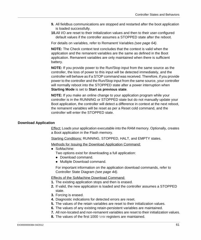
Controller States and Behaviors
9. All fieldbus communications are stopped and restarted after the boot application is loaded successfully.
10.All I/O are reset to their initialization values and then to their user-configured default values if the controller assumes a STOPPED state after the reboot.
For details on variables, refer to Remanent Variables (see page 64).
NOTE: The Check context test concludes that the context is valid when the application and the remanent variables are the same as defined in the Boot application. Remanent variables are only maintained when there is sufficient battery.
NOTE: If you provide power to the Run/Stop input from the same source as the controller, the loss of power to this input will be detected immediately, and the controller will behave as if a STOP command was received. Therefore, if you provide power to the controller and the Run/Stop input from the same source, your controller will normally reboot into the STOPPED state after a power interruption when Starting Mode is set to Start as previous state.
NOTE: If you make an online change to your application program while your controller is in the RUNNING or STOPPED state but do not manually update your Boot application, the controller will detect a difference in context at the next reboot, the remanent variables will be reset as per a Reset cold command, and the controller will enter the STOPPED state.
Download Application
Effect: Loads your application executable into the RAM memory. Optionally, creates a Boot application in the Flash memory.
Starting Conditions: RUNNING, STOPPED, HALT, and EMPTY states.
Methods for Issuing the Download Application Command:SoMachine:Two options exist for downloading a full application:
Download command.Multiple Download command.
For important information on the application download commands, refer to Controller State Diagram (see page 44).
Effects of the SoMachine Download Command:1. The existing application stops and then is erased.2. If valid, the new application is loaded and the controller assumes a STOPPED
state.3. Forcing is erased.4. Diagnostic indications for detected errors are reset.5. The values of the retain variables are reset to their initialization values.6. The values of any existing retain-persistent variables are maintained.7. All non-located and non-remanent variables are reset to their initialization values.8. The values of the first 1000 %MW registers are maintained.
EIO0000000384 04/2012 61
Controller States and Behaviors
9. The values of %MW1000 to %MW59999 registers are reset to 0.10.All fieldbus communications are stopped and then any configured fieldbus of the
new application is started after the download is complete.11.All I/O are reset to their initialization values and then set to the new user-
configured default values after the download is complete.
For details on variables, refer to Remanent Variables (see page 64).
62 EIO0000000384 04/2012
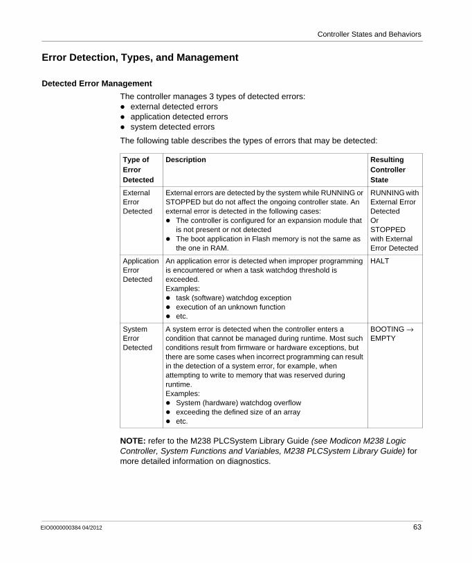
Controller States and Behaviors
Error Detection, Types, and Management
Detected Error Management
The controller manages 3 types of detected errors:external detected errorsapplication detected errorssystem detected errors
The following table describes the types of errors that may be detected:
NOTE: refer to the M238 PLCSystem Library Guide (see Modicon M238 Logic Controller, System Functions and Variables, M238 PLCSystem Library Guide) for more detailed information on diagnostics.
Type of Error Detected
Description Resulting Controller State
External Error Detected
External errors are detected by the system while RUNNING or STOPPED but do not affect the ongoing controller state. An external error is detected in the following cases:
The controller is configured for an expansion module that is not present or not detectedThe boot application in Flash memory is not the same as the one in RAM.
RUNNING with External Error DetectedOrSTOPPED with External Error Detected
Application Error Detected
An application error is detected when improper programming is encountered or when a task watchdog threshold is exceeded.Examples:
task (software) watchdog exceptionexecution of an unknown functionetc.
HALT
System Error Detected
A system error is detected when the controller enters a condition that cannot be managed during runtime. Most such conditions result from firmware or hardware exceptions, but there are some cases when incorrect programming can result in the detection of a system error, for example, when attempting to write to memory that was reserved during runtime. Examples:
System (hardware) watchdog overflowexceeding the defined size of an arrayetc.
BOOTING → EMPTY
EIO0000000384 04/2012 63
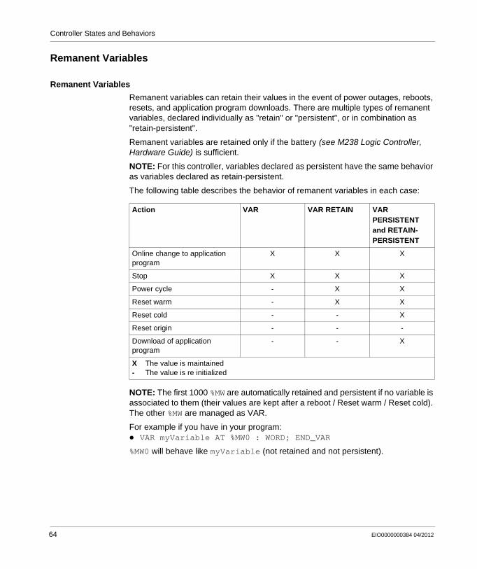
Controller States and Behaviors
Remanent Variables
Remanent Variables
Remanent variables can retain their values in the event of power outages, reboots, resets, and application program downloads. There are multiple types of remanent variables, declared individually as "retain" or "persistent", or in combination as "retain-persistent".
Remanent variables are retained only if the battery (see M238 Logic Controller, Hardware Guide) is sufficient.
NOTE: For this controller, variables declared as persistent have the same behavior as variables declared as retain-persistent.
The following table describes the behavior of remanent variables in each case:
NOTE: The first 1000 %MW are automatically retained and persistent if no variable is associated to them (their values are kept after a reboot / Reset warm / Reset cold). The other %MW are managed as VAR.
For example if you have in your program:VAR myVariable AT %MW0 : WORD; END_VAR
%MW0 will behave like myVariable (not retained and not persistent).
Action VAR VAR RETAIN VAR PERSISTENT and RETAIN-PERSISTENT
Online change to application program
X X X
Stop X X X
Power cycle - X X
Reset warm - X X
Reset cold - - X
Reset origin - - -
Download of application program
- - X
X The value is maintained- The value is re initialized
64 EIO0000000384 04/2012
EIO0000000384 04/2012
8
Modicon M238 Logic Controller
Controller Device Editor
EIO0000000384 04/2012
Controller Device Editor
Introduction
This chapter describes how to configure the controller.
What’s in this Chapter?
This chapter contains the following topics:
Topic Page
Controller Parameters 66
Applications 68
PLC Settings 69
Services 71
65
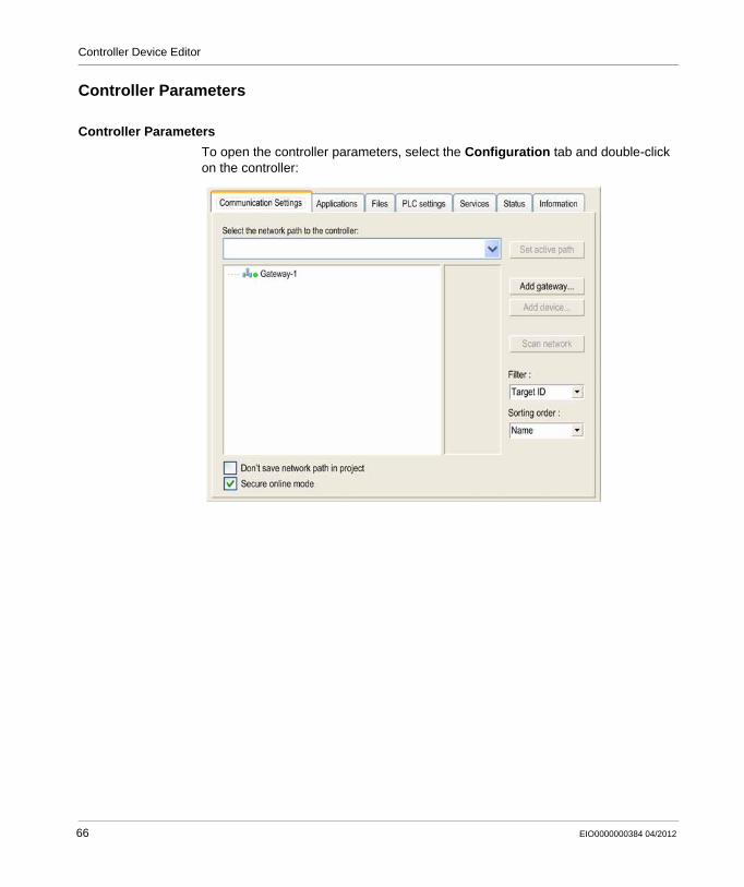
Controller Device Editor
Controller Parameters
Controller Parameters
To open the controller parameters, select the Configuration tab and double-click on the controller:
66 EIO0000000384 04/2012
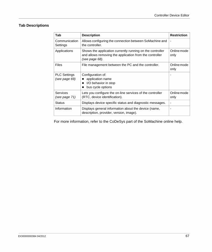
Controller Device Editor
Tab Descriptions
For more information, refer to the CoDeSys part of the SoMachine online help.
Tab Description Restriction
Communication Settings
Allows configuring the connection between SoMachine and the controller.
-
Applications Shows the application currently running on the controller and allows removing the application from the controller (see page 68).
Online mode only
Files File management between the PC and the controller. Online mode only
PLC Settings (see page 69)
Configuration of:application nameI/O behavior in stopbus cycle options
-
Services (see page 71)
Lets you configure the on-line services of the controller (RTC, device identification).
Online mode only
Status Displays device specific status and diagnostic messages. -
Information Displays general information about the device (name, description, provider, version, image).
-
EIO0000000384 04/2012 67
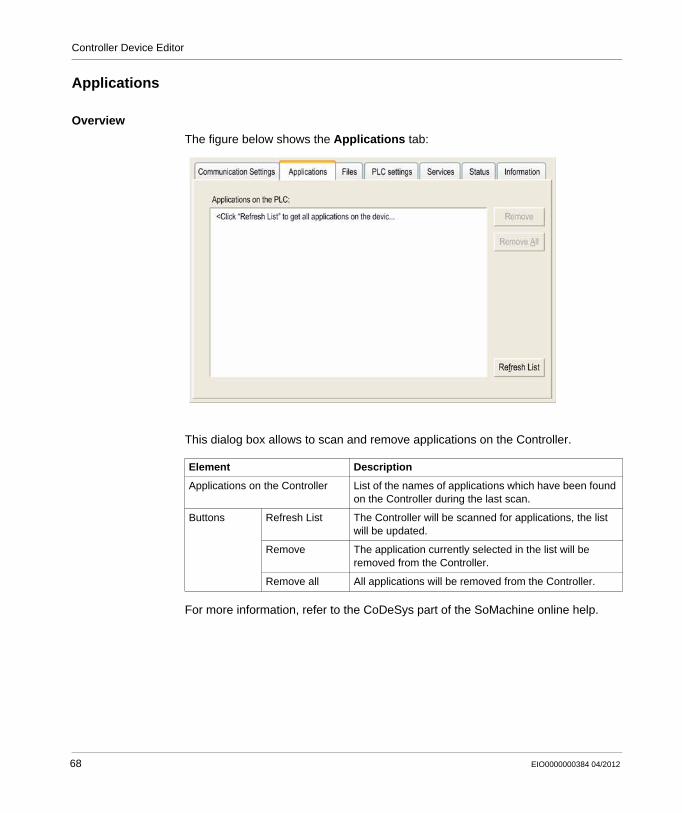
Controller Device Editor
Applications
Overview
The figure below shows the Applications tab:
This dialog box allows to scan and remove applications on the Controller.
For more information, refer to the CoDeSys part of the SoMachine online help.
Element Description
Applications on the Controller List of the names of applications which have been found on the Controller during the last scan.
Buttons Refresh List The Controller will be scanned for applications, the list will be updated.
Remove The application currently selected in the list will be removed from the Controller.
Remove all All applications will be removed from the Controller.
68 EIO0000000384 04/2012
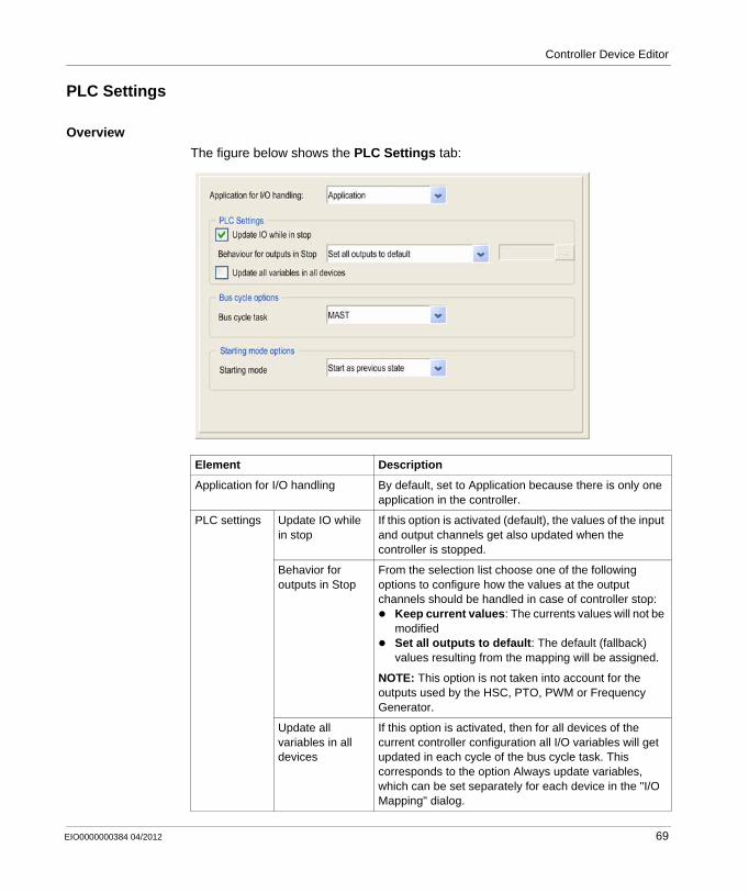
Controller Device Editor
PLC Settings
Overview
The figure below shows the PLC Settings tab:
Element Description
Application for I/O handling By default, set to Application because there is only one application in the controller.
PLC settings Update IO while in stop
If this option is activated (default), the values of the input and output channels get also updated when the controller is stopped.
Behavior for outputs in Stop
From the selection list choose one of the following options to configure how the values at the output channels should be handled in case of controller stop:
Keep current values: The currents values will not be modifiedSet all outputs to default: The default (fallback) values resulting from the mapping will be assigned.
NOTE: This option is not taken into account for the outputs used by the HSC, PTO, PWM or Frequency Generator.
Update all variables in all devices
If this option is activated, then for all devices of the current controller configuration all I/O variables will get updated in each cycle of the bus cycle task. This corresponds to the option Always update variables, which can be set separately for each device in the "I/O Mapping" dialog.
EIO0000000384 04/2012 69
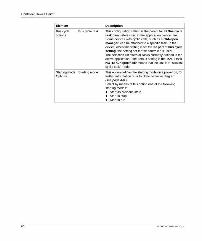
Controller Device Editor
Bus cycle options
Bus cycle task This configuration setting is the parent for all Bus cycle task parameters used in the application device tree.Some devices with cyclic calls, such as a CANopen manager, can be attached to a specific task. In the device, when this setting is set to Use parent bus cycle setting, the setting set for the controller is used.The selection list offers all tasks currently defined in the active application. The default setting is the MAST task.NOTE: <unspecified> means that the task is in "slowest cyclic task" mode.
Starting mode Options
Starting mode This option defines the starting mode on a power on, for further information refer to State behavior diagram (see page 44).)Select by means of this option one of the following starting modes:
Start as previous stateStart in stopStart in run
Element Description
70 EIO0000000384 04/2012
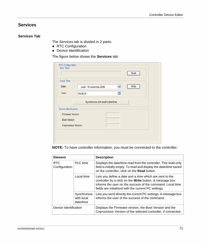
Controller Device Editor
Services
Services Tab
The Services tab is divided in 2 parts: RTC Configuration Device Identification
The figure below shows the Services tab:
NOTE: To have controller information, you must be connected to the controller.
Element Description
RTC Configuration
PLC time Displays the date/time read from the controller. This read-only field is initially empty. To read and display the date/time saved on the controller, click on the Read button.
Local time Lets you define a date and a time which are sent to the controller by a click on the Write button. A message box informs the user on the success of the command. Local time fields are initialized with the current PC settings.
Synchronize with local date/time
Lets you send directly the current PC settings. A message box informs the user of the success of the command.
Device Identification Displays the Firmware version, the Boot Version and the Coprocessor Version of the selected controller, if connected.
EIO0000000384 04/2012 71

Controller Device Editor
72 EIO0000000384 04/2012
EIO0000000384 04/2012
9
Modicon M238 Logic Controller
M238 Embedded Functions
EIO0000000384 04/2012
M238 Embedded Functions
Overview
This chapter describes the embedded functions of the Modicon M238 Logic Controller.
Each embedded function uses inputs and outputs.
The Modicon M238 Logic Controller with DC power supply has:14 digital inputs, including 8 fast inputs (see M238 Logic Controller, Hardware Guide)10 digital outputs, including 4 fast outputs (see M238 Logic Controller, Hardware Guide)
The Modicon M238 Logic Controller with AC power supply has:14 digital inputs, including 8 fast inputs (see M238 Logic Controller, Hardware Guide)10 digital outputs, including 6 relay outputs (see M238 Logic Controller, Hardware Guide)
What’s in this Chapter?
This chapter contains the following topics:
Topic Page
HSC Embedded Function 74
I/O Embedded Function 76
PTO_PWM Embedded Function 80
73
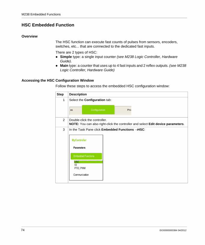
M238 Embedded Functions
HSC Embedded Function
Overview
The HSC function can execute fast counts of pulses from sensors, encoders, switches, etc... that are connected to the dedicated fast inputs.
There are 2 types of HSC:Simple type: a single input counter (see M238 Logic Controller, Hardware Guide).Main type: a counter that uses up to 4 fast inputs and 2 reflex outputs. (see M238 Logic Controller, Hardware Guide)
Accessing the HSC Configuration Window
Follow these steps to access the embedded HSC configuration window:
Step Description
1 Select the Configuration tab:
2 Double-click the controller.NOTE: You can also right-click the controller and select Edit device parameters.
3 In the Task Pane click Embedded Functions → HSC:
74 EIO0000000384 04/2012
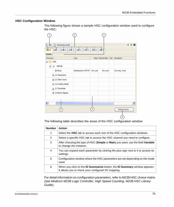
M238 Embedded Functions
HSC Configuration Window
The following figure shows a sample HSC configuration window used to configure the HSC:
The following table describes the areas of the HSC configuration window:
For detail information on configuration parameters, refer to M238 HSC choice matrix (see Modicon M238 Logic Controller, High Speed Counting, M238 HSC Library Guide).
Number Action
1 Select the HSC tab to access each one of the HSC configuration windows.
2 Select a specific HSC tab to access the HSC channel you need to configure.
3 After choosing the type of HSC (Simple or Main) you want, use the field Variable to change the instance.
4 You can expand each parameter by clicking the plus sign next to it to access its settings.
5 Configuration window where the HSC parameters are set depending on the mode used.
6 When you click on the IO Summarize button, the IO Summary window appears. It allows you to check your configured I/O mapping.
EIO0000000384 04/2012 75
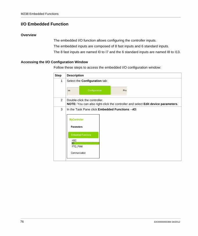
M238 Embedded Functions
I/O Embedded Function
Overview
The embedded I/O function allows configuring the controller inputs.
The embedded inputs are composed of 8 fast inputs and 6 standard inputs.
The 8 fast inputs are named I0 to I7 and the 6 standard inputs are named I8 to I13.
Accessing the I/O Configuration Window
Follow these steps to access the embedded I/O configuration window:
Step Description
1 Select the Configuration tab:
2 Double-click the controller.NOTE: You can also right-click the controller and select Edit device parameters.
3 In the Task Pane click Embedded Functions → IO:
76 EIO0000000384 04/2012
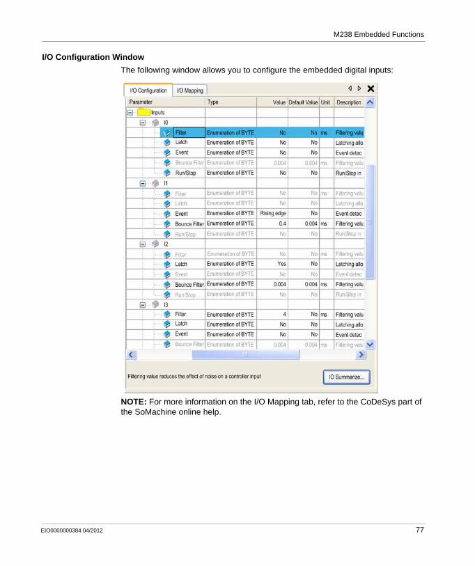
M238 Embedded Functions
I/O Configuration Window
The following window allows you to configure the embedded digital inputs:
NOTE: For more information on the I/O Mapping tab, refer to the CoDeSys part of the SoMachine online help.
EIO0000000384 04/2012 77
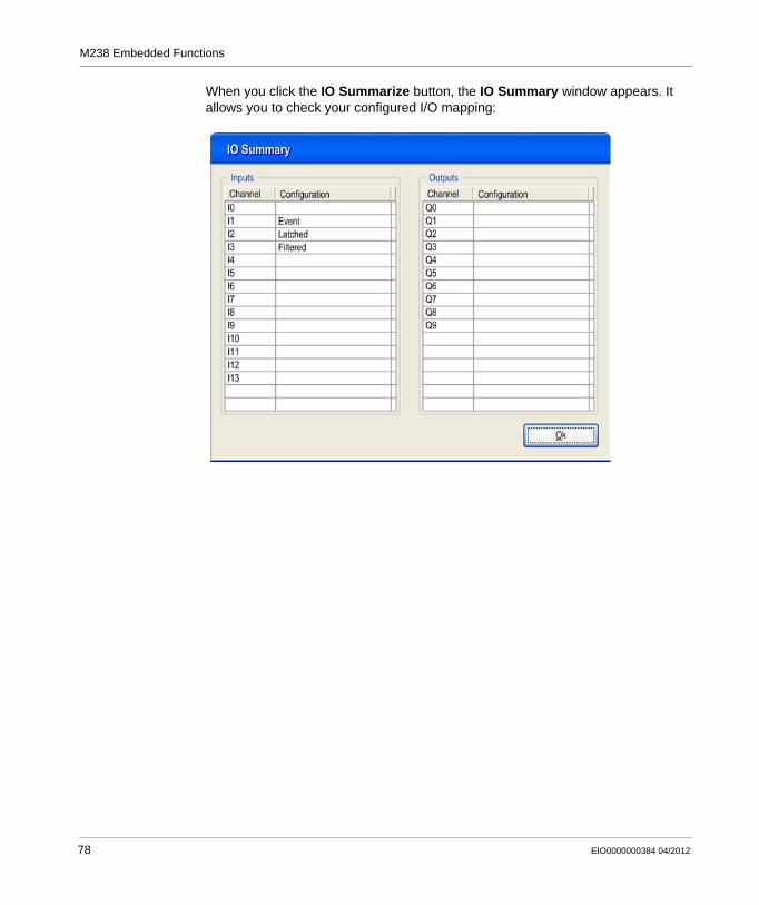
M238 Embedded Functions
When you click the IO Summarize button, the IO Summary window appears. It allows you to check your configured I/O mapping:
78 EIO0000000384 04/2012
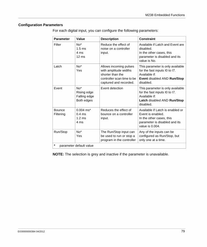
M238 Embedded Functions
Configuration Parameters
For each digital input, you can configure the following parameters:
NOTE: The selection is grey and inactive if the parameter is unavailable.
Parameter Value Description Constraint
Filter No*1.5 ms4 ms12 ms
Reduce the effect of noise on a controller input.
Available if Latch and Event are disabled.In the other cases, this parameter is disabled and its value is No.
Latch No*Yes
Allows incoming pulses with amplitude widths shorter than the controller scan time to be captured and recorded.
This parameter is only available for the fast inputs I0 to I7.Available if:Event disabled AND Run/Stop disabled.
Event No*Rising edgeFalling edgeBoth edges
Event detection This parameter is only available for the fast inputs I0 to I7.Available if:Latch disabled AND Run/Stop disabled.
Bounce Filtering
0.004 ms*0.4 ms1.2 ms4 ms
Reduces the effect of bounce on a controller input.
Available if Latch is enabled or Event is enabled.In the other cases, this parameter is disabled and its value is 0.004.
Run/Stop No*Yes
The Run/Stop input can be used to run or stop a program in the controller
Any of the inputs can be configured as Run/Stop, but only one at a time.
* parameter default value
EIO0000000384 04/2012 79
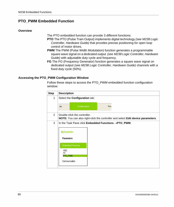
M238 Embedded Functions
PTO_PWM Embedded Function
Overview
The PTO embedded function can provide 3 different functions:PTO The PTO (Pulse Train Output) implements digital technology (see M238 Logic
Controller, Hardware Guide) that provides precise positioning for open loop control of motor drives.
PWM The PWM (Pulse Width Modulation) function generates a programmable square wave signal on a dedicated output (see M238 Logic Controller, Hardware Guide) with adjustable duty cycle and frequency.
FG The FG (Frequency Generator) function generates a square wave signal on dedicated output (see M238 Logic Controller, Hardware Guide) channels with a fixed duty cycle (50%).
Accessing the PTO_PWM Configuration Window
Follow these steps to access the PTO_PWM embedded function configuration window:
Step Description
1 Select the Configuration tab:
2 Double-click the controller.NOTE: You can also right-click the controller and select Edit device parameters.
3 In the Task Pane click Embedded Functions → PTO_PWM:
80 EIO0000000384 04/2012
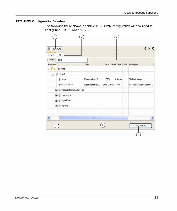
M238 Embedded Functions
PTO_PWM Configuration Window
The following figure shows a sample PTO_PWM configuration window used to configure a PTO, PWM or FG:
EIO0000000384 04/2012 81
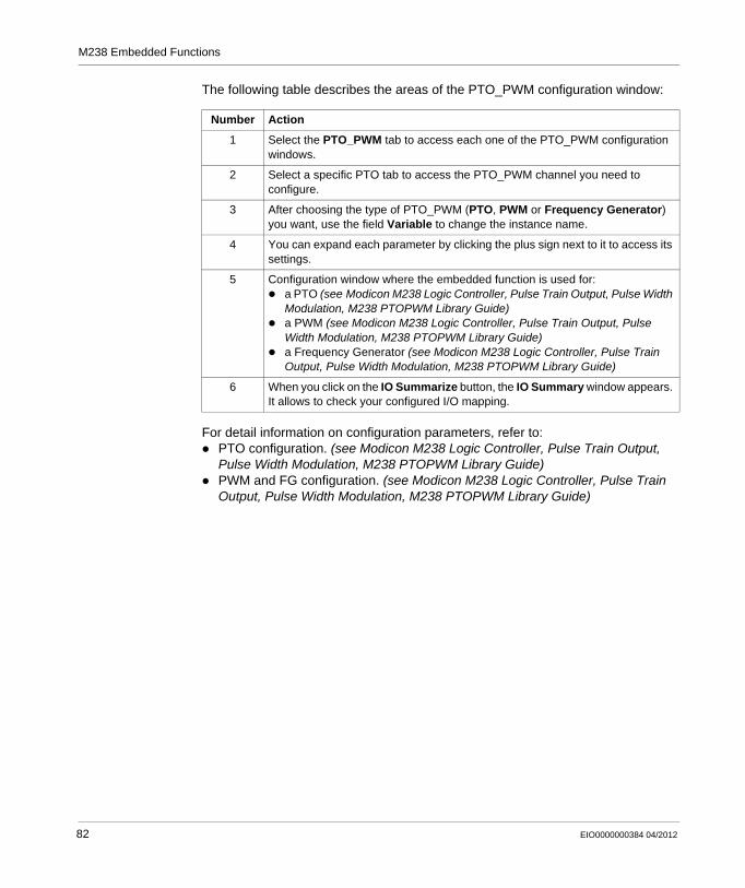
M238 Embedded Functions
The following table describes the areas of the PTO_PWM configuration window:
For detail information on configuration parameters, refer to:PTO configuration. (see Modicon M238 Logic Controller, Pulse Train Output, Pulse Width Modulation, M238 PTOPWM Library Guide)PWM and FG configuration. (see Modicon M238 Logic Controller, Pulse Train Output, Pulse Width Modulation, M238 PTOPWM Library Guide)
Number Action
1 Select the PTO_PWM tab to access each one of the PTO_PWM configuration windows.
2 Select a specific PTO tab to access the PTO_PWM channel you need to configure.
3 After choosing the type of PTO_PWM (PTO, PWM or Frequency Generator) you want, use the field Variable to change the instance name.
4 You can expand each parameter by clicking the plus sign next to it to access its settings.
5 Configuration window where the embedded function is used for:a PTO (see Modicon M238 Logic Controller, Pulse Train Output, Pulse Width Modulation, M238 PTOPWM Library Guide)a PWM (see Modicon M238 Logic Controller, Pulse Train Output, Pulse Width Modulation, M238 PTOPWM Library Guide)a Frequency Generator (see Modicon M238 Logic Controller, Pulse Train Output, Pulse Width Modulation, M238 PTOPWM Library Guide)
6 When you click on the IO Summarize button, the IO Summary window appears. It allows to check your configured I/O mapping.
82 EIO0000000384 04/2012
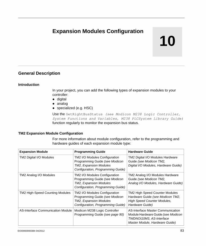
EIO0000000384 04/2012
10
Modicon M238 Logic Controller
Expansion Modules Configuration
EIO0000000384 04/2012
Expansion Modules Configuration
General Description
Introduction
In your project, you can add the following types of expansion modules to your controller:
digitalanalogspecialized (e.g. HSC)
Use the GetRightBusStatus (see Modicon M238 Logic Controller, System Functions and Variables, M238 PLCSystem Library Guide) function regularly to monitor the expansion bus status.
TM2 Expansion Module Configuration
For more information about module configuration, refer to the programming and hardware guides of each expansion module type:
Expansion Module Programming Guide Hardware Guide
TM2 Digital I/O Modules TM2 I/O Modules Configuration Programming Guide (see Modicon TM2, Expansion Modules Configuration, Programming Guide)
TM2 Digital I/O Modules Hardware Guide (see Modicon TM2, Digital I/O Modules, Hardware Guide)
TM2 Analog I/O Modules TM2 I/O Modules Configuration Programming Guide (see Modicon TM2, Expansion Modules Configuration, Programming Guide)
TM2 Analog I/O Modules Hardware Guide (see Modicon TM2, Analog I/O Modules, Hardware Guide)
TM2 High-Speed Counting Modules TM2 I/O Modules Configuration Programming Guide (see Modicon TM2, Expansion Modules Configuration, Programming Guide)
TM2 High Speed Counter Modules Hardware Guide (see Modicon TM2, High Speed Counter Modules, Hardware Guide)
AS-Interface Communication Module Modicon M238 Logic Controller Programming Guide (see page 90)
AS-Interface Master Communication Module Hardware Guide (see Modicon TWDNOI10M3, AS-Interface Master Module, Hardware Guide)
83

Expansion Modules Configuration
Maximum Hardware Configuration
Up to 7 expansion modules can be added to the controller.
84 EIO0000000384 04/2012
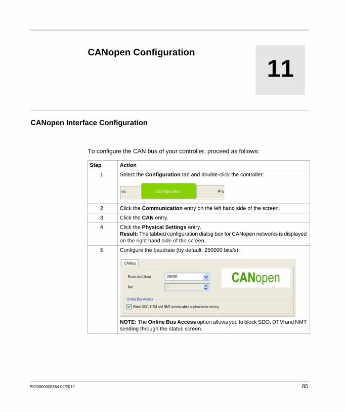
EIO0000000384 04/2012
11
Modicon M238 Logic Controller
CANopen Configuration
EIO0000000384 04/2012
CANopen Configuration
CANopen Interface Configuration
To configure the CAN bus of your controller, proceed as follows:
Step Action
1 Select the Configuration tab and double-click the controller:
2 Click the Communication entry on the left hand side of the screen.
3 Click the CAN entry.
4 Click the Physical Settings entry.Result: The tabbed configuration dialog box for CANopen networks is displayed on the right hand side of the screen.
5 Configure the baudrate (by default: 250000 bits/s):
NOTE: The Online Bus Access option allows you to block SDO, DTM and NMT sending through the status screen.
85
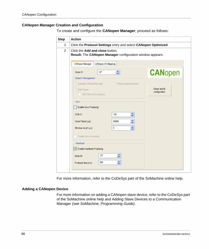
CANopen Configuration
CANopen Manager Creation and Configuration
To create and configure the CANopen Manager, proceed as follows:
For more information, refer to the CoDeSys part of the SoMachine online help.
Adding a CANopen Device
For more information on adding a CANopen slave device, refer to the CoDeSys part of the SoMachine online help and Adding Slave Devices to a Communication Manager (see SoMachine, Programming Guide).
Step Action
1 Click the Protocol Settings entry and select CANopen Optimized.
2 Click the Add and close button.Result: The CANopen Manager configuration window appears:
86 EIO0000000384 04/2012
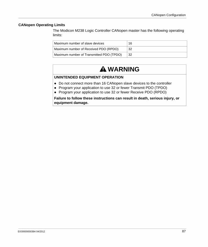
CANopen Configuration
CANopen Operating Limits
The Modicon M238 Logic Controller CANopen master has the following operating limits:
Maximum number of slave devices 16
Maximum number of Received PDO (RPDO) 32
Maximum number of Transmitted PDO (TPDO) 32
WARNINGUNINTENDED EQUIPMENT OPERATION
Do not connect more than 16 CANopen slave devices to the controllerProgram your application to use 32 or fewer Transmit PDO (TPDO)Program your application to use 32 or fewer Receive PDO (RPDO)
Failure to follow these instructions can result in death, serious injury, or equipment damage.
EIO0000000384 04/2012 87

CANopen Configuration
88 EIO0000000384 04/2012
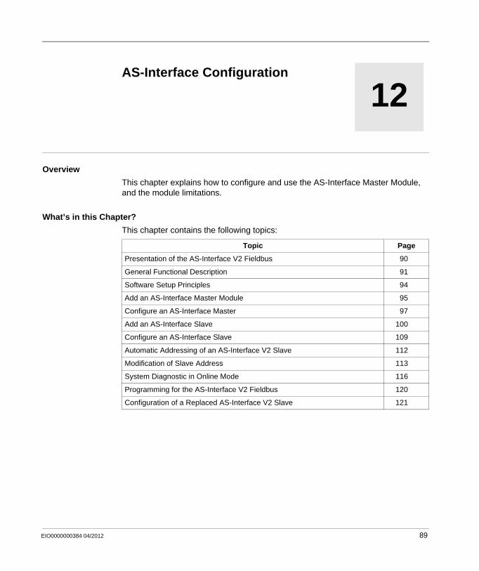
EIO0000000384 04/2012
12
Modicon M238 Logic Controller
AS-Interface Configuration
EIO0000000384 04/2012
AS-Interface Configuration
Overview
This chapter explains how to configure and use the AS-Interface Master Module, and the module limitations.
What’s in this Chapter?
This chapter contains the following topics:
Topic Page
Presentation of the AS-Interface V2 Fieldbus 90
General Functional Description 91
Software Setup Principles 94
Add an AS-Interface Master Module 95
Configure an AS-Interface Master 97
Add an AS-Interface Slave 100
Configure an AS-Interface Slave 109
Automatic Addressing of an AS-Interface V2 Slave 112
Modification of Slave Address 113
System Diagnostic in Online Mode 116
Programming for the AS-Interface V2 Fieldbus 120
Configuration of a Replaced AS-Interface V2 Slave 121
89
AS-Interface Configuration
Presentation of the AS-Interface V2 Fieldbus
Introduction
The AS-Interface Fieldbus (Actuator Sensor-Interface) allows the interconnection on a single cable of sensor devices and actuators, with the lowest level of automation.
These sensors/actuators will be defined in this documentation as slave devices.
NOTE: For more information about the TWDNOI10M3 expansion module, refer to the TWDNOI10M3 Communication Module Hardware Guide (see Modicon TWDNOI10M3, AS-Interface Master Module, Hardware Guide)
NOTE: All terms and definitions used in this chapter and throughout the document concerning AS-Interface are those as defined by the AS-Interface Association Specification version 2.11.
AS-Interface V2 Fieldbus
The AS-Interface Master module TWDNOI10M3 expansion module includes the following functionality:
M3 profile: This profile includes all the functionality defined by the AS-Interface V2 standardOne AS-Interface channel per moduleAutomatic addressing for the slave with the physical address set to 0Management of profiles and parametersProtection from polarity inversion on the bus inputs
The AS-Interface Fieldbus then allows:
Up to 31 standard address or 62 extended address slavesUp to 248 inputs and 186 outputsUp to 8 analog slaves (maximum of four analog channels per slave)A cycle time of 10 ms maximum
A maximum of 2 TWDNOI10M3 expansion modules can be connected to a M238.
90 EIO0000000384 04/2012
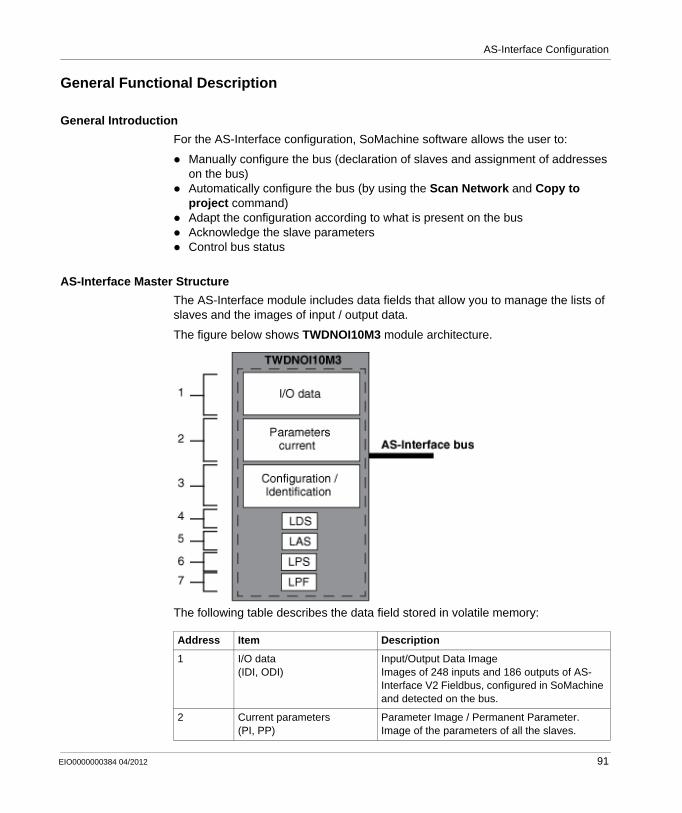
AS-Interface Configuration
General Functional Description
General Introduction
For the AS-Interface configuration, SoMachine software allows the user to:
Manually configure the bus (declaration of slaves and assignment of addresses on the bus)Automatically configure the bus (by using the Scan Network and Copy to project command) Adapt the configuration according to what is present on the busAcknowledge the slave parametersControl bus status
AS-Interface Master Structure
The AS-Interface module includes data fields that allow you to manage the lists of slaves and the images of input / output data.
The figure below shows TWDNOI10M3 module architecture.
The following table describes the data field stored in volatile memory:
Address Item Description
1 I/O data(IDI, ODI)
Input/Output Data ImageImages of 248 inputs and 186 outputs of AS-Interface V2 Fieldbus, configured in SoMachine and detected on the bus.
2 Current parameters(PI, PP)
Parameter Image / Permanent Parameter.Image of the parameters of all the slaves.
EIO0000000384 04/2012 91
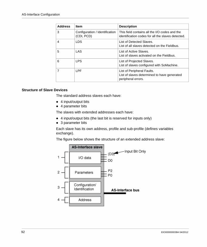
AS-Interface Configuration
Structure of Slave Devices
The standard address slaves each have:
4 input/output bits4 parameter bits
The slaves with extended addresses each have:
4 input/output bits (the last bit is reserved for inputs only)3 parameter bits
Each slave has its own address, profile and sub-profile (defines variables exchange).
The figure below shows the structure of an extended address slave:
3 Configuration / Identification(CDI, PCD)
This field contains all the I/O codes and the identification codes for all the slaves detected.
4 LDS List of Detected Slaves.List of all slaves detected on the Fieldbus.
5 LAS List of Active Slaves.List of slaves activated on the Fieldbus.
6 LPS List of Projected Slaves.List of slaves configured with SoMachine.
7 LPF List of Peripheral Faults.List of slaves determined to have generated peripheral errors.
Address Item Description
92 EIO0000000384 04/2012
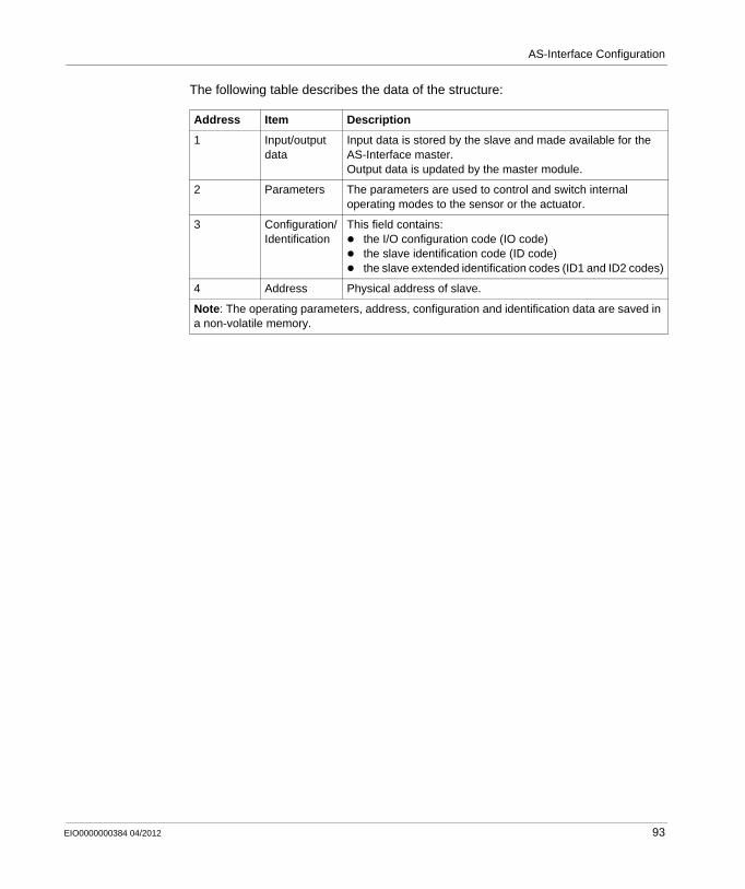
AS-Interface Configuration
The following table describes the data of the structure:
Address Item Description
1 Input/output data
Input data is stored by the slave and made available for the AS-Interface master.Output data is updated by the master module.
2 Parameters The parameters are used to control and switch internal operating modes to the sensor or the actuator.
3 Configuration/Identification
This field contains:the I/O configuration code (IO code)the slave identification code (ID code)the slave extended identification codes (ID1 and ID2 codes)
4 Address Physical address of slave.
Note: The operating parameters, address, configuration and identification data are saved in a non-volatile memory.
EIO0000000384 04/2012 93
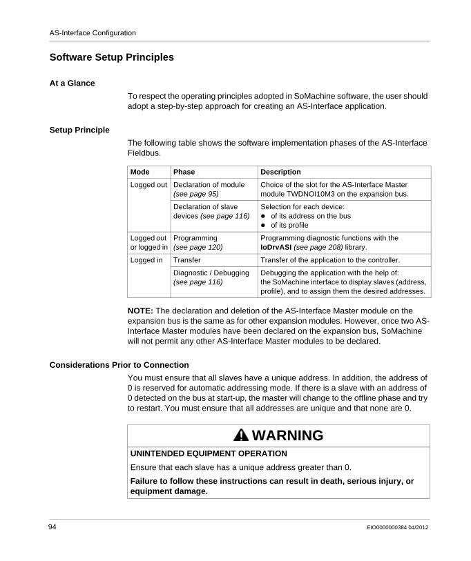
AS-Interface Configuration
Software Setup Principles
At a Glance
To respect the operating principles adopted in SoMachine software, the user should adopt a step-by-step approach for creating an AS-Interface application.
Setup Principle
The following table shows the software implementation phases of the AS-Interface Fieldbus.
NOTE: The declaration and deletion of the AS-Interface Master module on the expansion bus is the same as for other expansion modules. However, once two AS-Interface Master modules have been declared on the expansion bus, SoMachine will not permit any other AS-Interface Master modules to be declared.
Considerations Prior to Connection
You must ensure that all slaves have a unique address. In addition, the address of 0 is reserved for automatic addressing mode. If there is a slave with an address of 0 detected on the bus at start-up, the master will change to the offline phase and try to restart. You must ensure that all addresses are unique and that none are 0.
Mode Phase Description
Logged out Declaration of module (see page 95)
Choice of the slot for the AS-Interface Master module TWDNOI10M3 on the expansion bus.
Declaration of slave devices (see page 116)
Selection for each device:of its address on the busof its profile
Logged out or logged in
Programming (see page 120)
Programming diagnostic functions with the IoDrvASI (see page 208) library.
Logged in Transfer Transfer of the application to the controller.
Diagnostic / Debugging (see page 116)
Debugging the application with the help of:the SoMachine interface to display slaves (address, profile), and to assign them the desired addresses.
WARNINGUNINTENDED EQUIPMENT OPERATION
Ensure that each slave has a unique address greater than 0.
Failure to follow these instructions can result in death, serious injury, or equipment damage.
94 EIO0000000384 04/2012
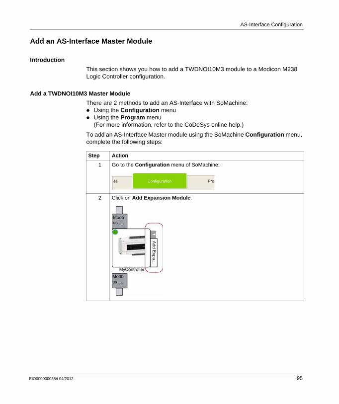
AS-Interface Configuration
Add an AS-Interface Master Module
Introduction
This section shows you how to add a TWDNOI10M3 module to a Modicon M238 Logic Controller configuration.
Add a TWDNOI10M3 Master Module
There are 2 methods to add an AS-Interface with SoMachine:Using the Configuration menuUsing the Program menu(For more information, refer to the CoDeSys online help.)
To add an AS-Interface Master module using the SoMachine Configuration menu, complete the following steps:
Step Action
1 Go to the Configuration menu of SoMachine:
2 Click on Add Expansion Module:
EIO0000000384 04/2012 95
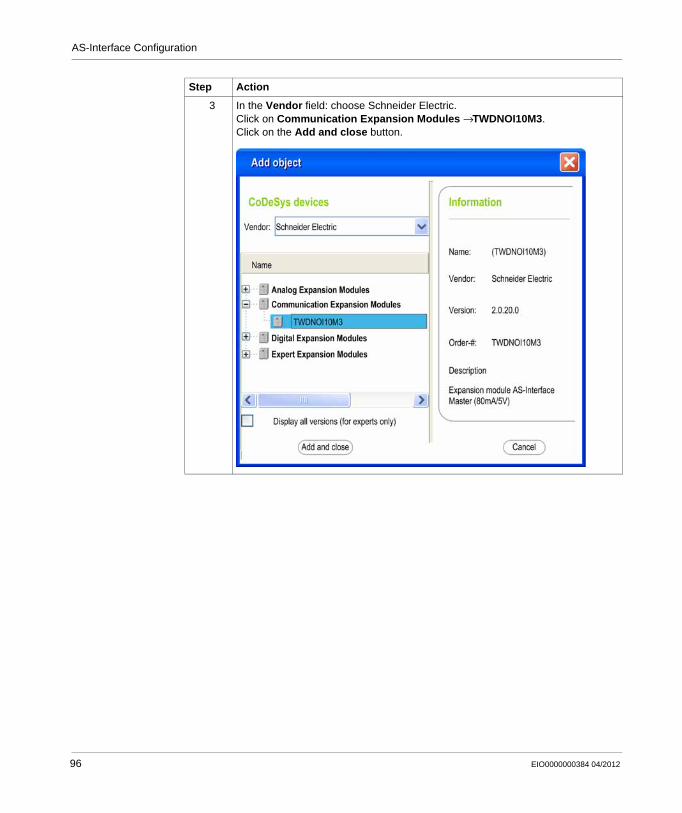
AS-Interface Configuration
3 In the Vendor field: choose Schneider Electric.Click on Communication Expansion Modules → TWDNOI10M3.Click on the Add and close button.
Step Action
96 EIO0000000384 04/2012
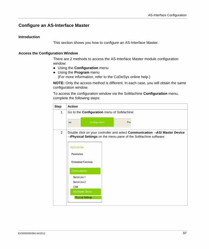
AS-Interface Configuration
Configure an AS-Interface Master
Introduction
This section shows you how to configure an AS-Interface Master.
Access the Configuration Window
There are 2 methods to access the AS-Interface Master module configuration window:
Using the Configuration menuUsing the Program menu(For more information, refer to the CoDeSys online help.)
NOTE: Only the access method is different. In each case, you will obtain the same configuration window.
To access the configuration window via the SoMachine Configuration menu, complete the following steps:
Step Action
1 Go to the Configuration menu of SoMachine:
2 Double click on your controller and select Communication → ASi Master Device → Physical Settings on the menu pane of the SoMachine software:
EIO0000000384 04/2012 97
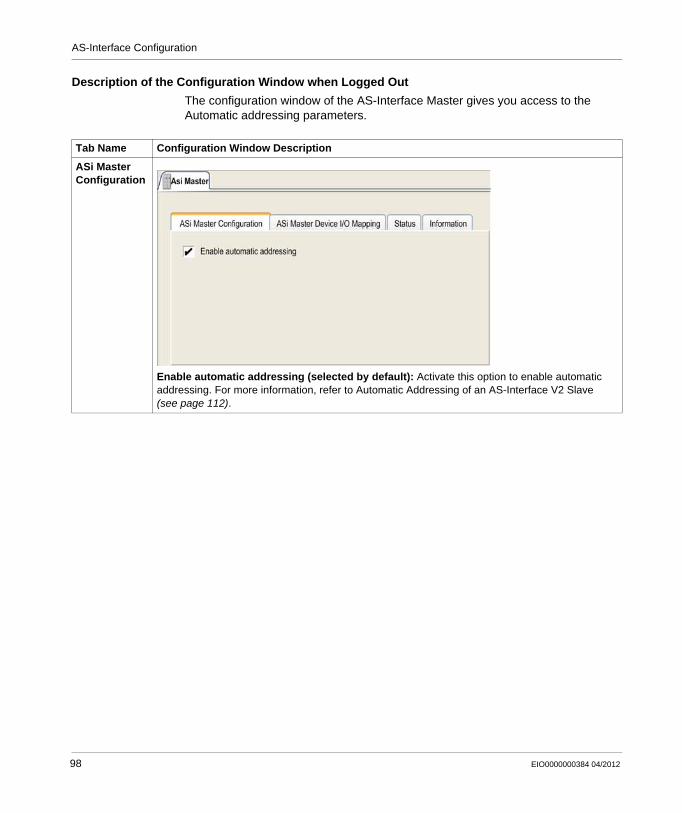
AS-Interface Configuration
Description of the Configuration Window when Logged Out
The configuration window of the AS-Interface Master gives you access to the Automatic addressing parameters.
Tab Name Configuration Window Description
ASi Master Configuration
Enable automatic addressing (selected by default): Activate this option to enable automatic addressing. For more information, refer to Automatic Addressing of an AS-Interface V2 Slave (see page 112).
98 EIO0000000384 04/2012
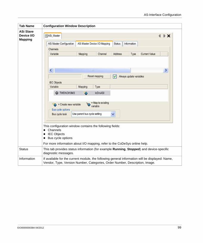
AS-Interface Configuration
ASi Slave Device I/O Mapping
This configuration window contains the following fields:ChannelsIEC ObjectsBus cycle options
For more information about I/O mapping, refer to the CoDeSys online help.
Status This tab provides status information (for example Running, Stopped) and device-specific diagnostic messages.
Information If available for the current module, the following general information will be displayed: Name, Vendor, Type, Version Number, Categories, Order Number, Description, Image.
Tab Name Configuration Window Description
EIO0000000384 04/2012 99
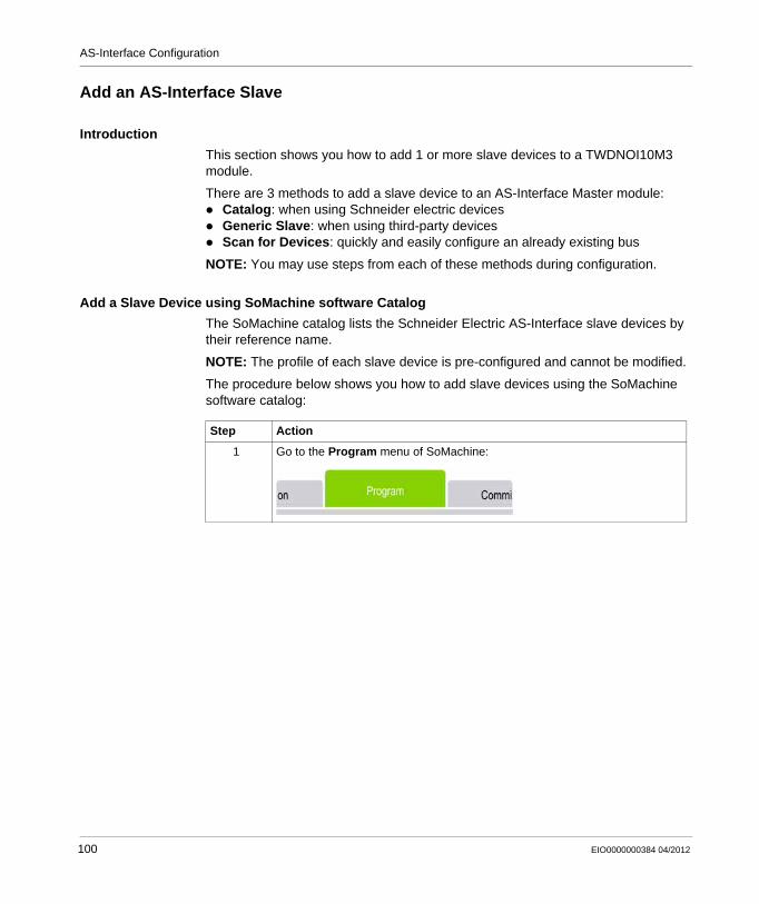
AS-Interface Configuration
Add an AS-Interface Slave
Introduction
This section shows you how to add 1 or more slave devices to a TWDNOI10M3 module.
There are 3 methods to add a slave device to an AS-Interface Master module:Catalog: when using Schneider electric devicesGeneric Slave: when using third-party devicesScan for Devices: quickly and easily configure an already existing bus
NOTE: You may use steps from each of these methods during configuration.
Add a Slave Device using SoMachine software Catalog
The SoMachine catalog lists the Schneider Electric AS-Interface slave devices by their reference name.
NOTE: The profile of each slave device is pre-configured and cannot be modified.
The procedure below shows you how to add slave devices using the SoMachine software catalog:
Step Action
1 Go to the Program menu of SoMachine:
100 EIO0000000384 04/2012
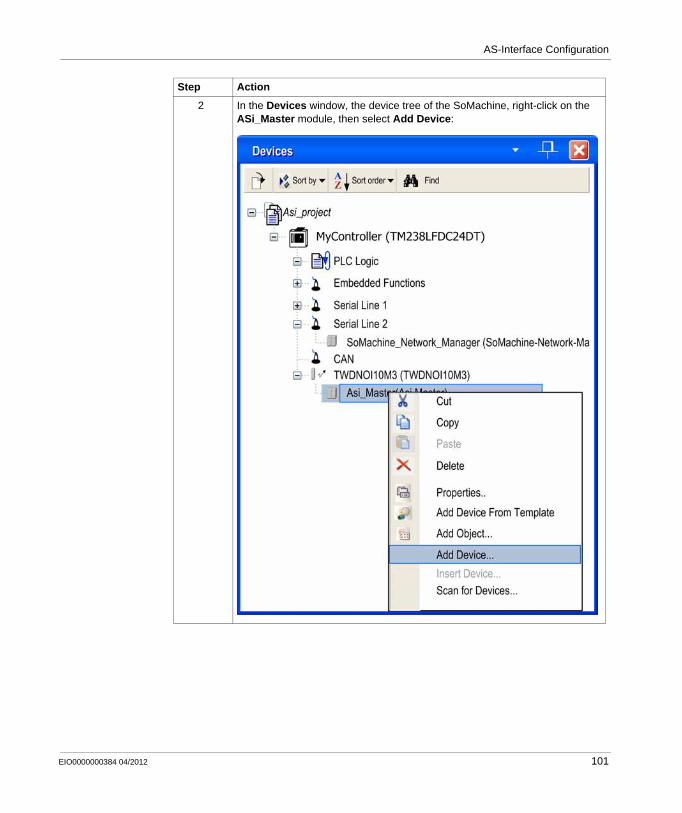
AS-Interface Configuration
2 In the Devices window, the device tree of the SoMachine, right-click on the ASi_Master module, then select Add Device:
Step Action
EIO0000000384 04/2012 101
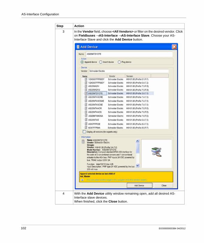
AS-Interface Configuration
3 In the Vendor field, choose <All Vendors> or filter on the desired vendor. Click on Fieldbuses → AS-Interface → AS-Interface Slave. Choose your AS-Interface Slave and click the Add Device button.
4 With the Add Device utility window remaining open, add all desired AS-Interface slave devices.When finished, click the Close button.
Step Action
102 EIO0000000384 04/2012
AS-Interface Configuration
Add a Slave Device with the Scan For Devices Command
The Scan For Devices command will search all AS-Interface Slave devices connected to the TWDNOI10M3 master module. This function requires that the master module is configured before executing the Scan For Devices command.
The procedure below shows you how to add slave devices with the SoMachine software Scan For Devices command:
Step Action
1 Log in to your Controller.NOTE: Only the right-bus configuration including your master module must be correctly set up for this step. No application program is needed.
EIO0000000384 04/2012 103
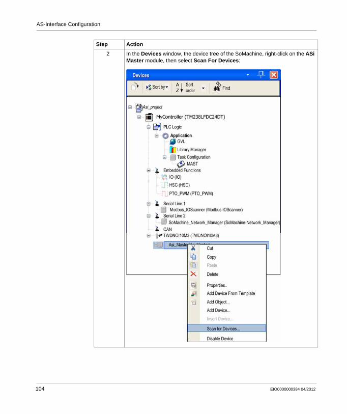
AS-Interface Configuration
2 In the Devices window, the device tree of the SoMachine, right-click on the ASi Master module, then select Scan For Devices:
Step Action
104 EIO0000000384 04/2012
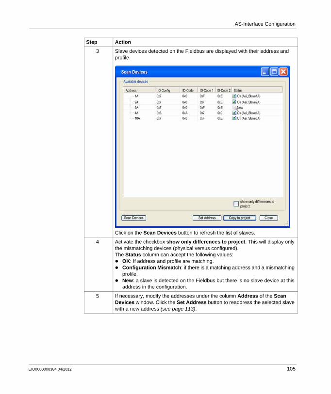
AS-Interface Configuration
3 Slave devices detected on the Fieldbus are displayed with their address and profile.
Click on the Scan Devices button to refresh the list of slaves.
4 Activate the checkbox show only differences to project. This will display only the mismatching devices (physical versus configured).The Status column can accept the following values:
OK: If address and profile are matching.Configuration Mismatch: if there is a matching address and a mismatching profile.New: a slave is detected on the Fieldbus but there is no slave device at this address in the configuration.
5 If necessary, modify the addresses under the column Address of the Scan Devices window. Click the Set Address button to readdress the selected slave with a new address (see page 113).
Step Action
EIO0000000384 04/2012 105
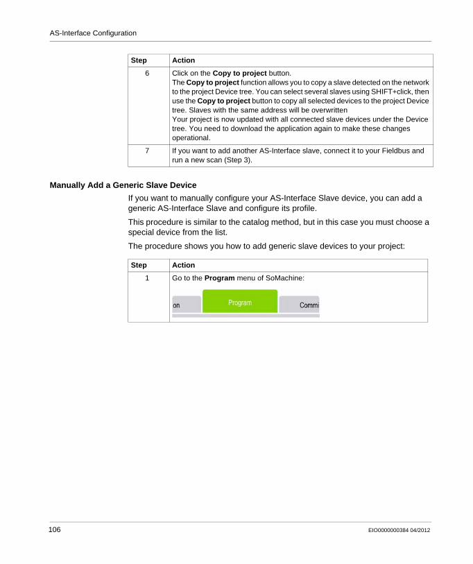
AS-Interface Configuration
Manually Add a Generic Slave Device
If you want to manually configure your AS-Interface Slave device, you can add a generic AS-Interface Slave and configure its profile.
This procedure is similar to the catalog method, but in this case you must choose a special device from the list.
The procedure shows you how to add generic slave devices to your project:
6 Click on the Copy to project button.The Copy to project function allows you to copy a slave detected on the network to the project Device tree. You can select several slaves using SHIFT+click, then use the Copy to project button to copy all selected devices to the project Device tree. Slaves with the same address will be overwrittenYour project is now updated with all connected slave devices under the Device tree. You need to download the application again to make these changes operational.
7 If you want to add another AS-Interface slave, connect it to your Fieldbus and run a new scan (Step 3).
Step Action
Step Action
1 Go to the Program menu of SoMachine:
106 EIO0000000384 04/2012
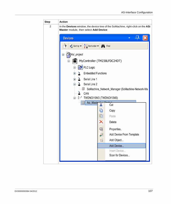
AS-Interface Configuration
2 In the Devices window, the device tree of the SoMachine, right-click on the ASi Master module, then select Add Device:
Step Action
EIO0000000384 04/2012 107
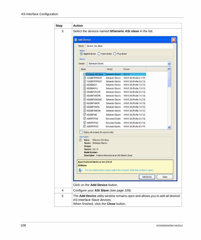
AS-Interface Configuration
3 Select the devices named 0/Generic ASi slave in the list:
Click on the Add Device button.
4 Configure your ASi Slave (see page 109).
5 The Add Device utility window remains open and allows you to add all desired AS-Interface Slave devices.When finished, click the Close button.
Step Action
108 EIO0000000384 04/2012
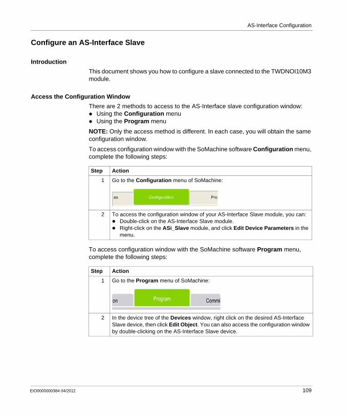
AS-Interface Configuration
Configure an AS-Interface Slave
Introduction
This document shows you how to configure a slave connected to the TWDNOI10M3 module.
Access the Configuration Window
There are 2 methods to access to the AS-Interface slave configuration window:Using the Configuration menuUsing the Program menu
NOTE: Only the access method is different. In each case, you will obtain the same configuration window.
To access configuration window with the SoMachine software Configuration menu, complete the following steps:
To access configuration window with the SoMachine software Program menu, complete the following steps:
Step Action
1 Go to the Configuration menu of SoMachine:
2 To access the configuration window of your AS-Interface Slave module, you can:Double-click on the AS-Interface Slave module.Right-click on the ASi_Slave module, and click Edit Device Parameters in the menu.
Step Action
1 Go to the Program menu of SoMachine:
2 In the device tree of the Devices window, right click on the desired AS-Interface Slave device, then click Edit Object. You can also access the configuration window by double-clicking on the AS-Interface Slave device.
EIO0000000384 04/2012 109
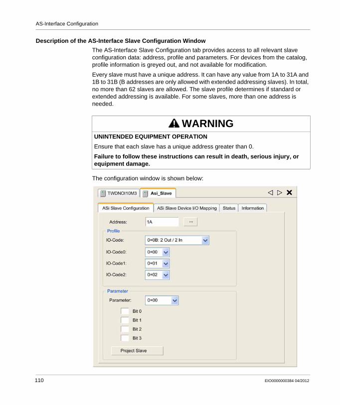
AS-Interface Configuration
Description of the AS-Interface Slave Configuration Window
The AS-Interface Slave Configuration tab provides access to all relevant slave configuration data: address, profile and parameters. For devices from the catalog, profile information is greyed out, and not available for modification.
Every slave must have a unique address. It can have any value from 1A to 31A and 1B to 31B (B addresses are only allowed with extended addressing slaves). In total, no more than 62 slaves are allowed. The slave profile determines if standard or extended addressing is available. For some slaves, more than one address is needed.
The configuration window is shown below:
WARNINGUNINTENDED EQUIPMENT OPERATION
Ensure that each slave has a unique address greater than 0.
Failure to follow these instructions can result in death, serious injury, or equipment damage.
110 EIO0000000384 04/2012
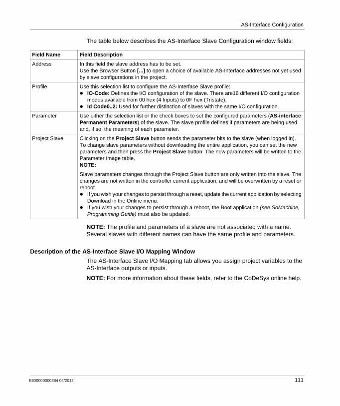
AS-Interface Configuration
The table below describes the AS-Interface Slave Configuration window fields:
NOTE: The profile and parameters of a slave are not associated with a name. Several slaves with different names can have the same profile and parameters.
Description of the AS-Interface Slave I/O Mapping Window
The AS-Interface Slave I/O Mapping tab allows you assign project variables to the AS-Interface outputs or inputs.
NOTE: For more information about these fields, refer to the CoDeSys online help.
Field Name Field Description
Address In this field the slave address has to be set.Use the Browser Button [...] to open a choice of available AS-Interface addresses not yet used by slave configurations in the project.
Profile Use this selection list to configure the AS-Interface Slave profile:IO-Code: Defines the I/O configuration of the slave. There are16 different I/O configuration modes available from 00 hex (4 Inputs) to 0F hex (Tristate).Id Code0..2: Used for further distinction of slaves with the same I/O configuration.
Parameter Use either the selection list or the check boxes to set the configured parameters (AS-interface Permanent Parameters) of the slave. The slave profile defines if parameters are being used and, if so, the meaning of each parameter.
Project Slave Clicking on the Project Slave button sends the parameter bits to the slave (when logged in).To change slave parameters without downloading the entire application, you can set the new parameters and then press the Project Slave button. The new parameters will be written to the Parameter Image table.NOTE:
Slave parameters changes through the Project Slave button are only written into the slave. The changes are not written in the controller current application, and will be overwritten by a reset or reboot.
If you wish your changes to persist through a reset, update the current application by selecting Download in the Online menu.If you wish your changes to persist through a reboot, the Boot application (see SoMachine, Programming Guide) must also be updated.
EIO0000000384 04/2012 111
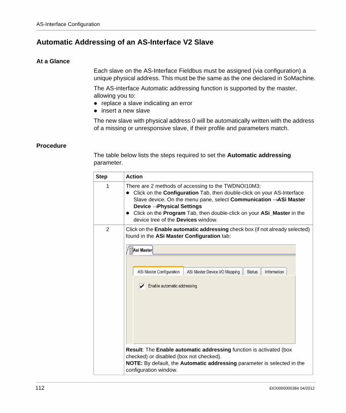
AS-Interface Configuration
Automatic Addressing of an AS-Interface V2 Slave
At a Glance
Each slave on the AS-Interface Fieldbus must be assigned (via configuration) a unique physical address. This must be the same as the one declared in SoMachine.
The AS-interface Automatic addressing function is supported by the master, allowing you to:
replace a slave indicating an errorinsert a new slave
The new slave with physical address 0 will be automatically written with the address of a missing or unresponsive slave, if their profile and parameters match.
Procedure
The table below lists the steps required to set the Automatic addressing parameter.
Step Action
1 There are 2 methods of accessing to the TWDNOI10M3:Click on the Configuration Tab, then double-click on your AS-Interface Slave device. On the menu pane, select Communication → ASi Master Device → Physical SettingsClick on the Program Tab, then double-click on your ASi_Master in the device tree of the Devices window.
2 Click on the Enable automatic addressing check box (if not already selected) found in the ASi Master Configuration tab:
Result: The Enable automatic addressing function is activated (box checked) or disabled (box not checked).NOTE: By default, the Automatic addressing parameter is selected in the configuration window.
112 EIO0000000384 04/2012
AS-Interface Configuration
Modification of Slave Address
At a Glance
From the Scan Devices interface, you can modify the address of a slave.
Modification of Slave Address
The following table shows the steps required to modify a slave address:
Step Description
1 Log in to your Controller.NOTE: Only the right-bus configuration from your master module must be correctly set up at this step. No application program is needed.
EIO0000000384 04/2012 113
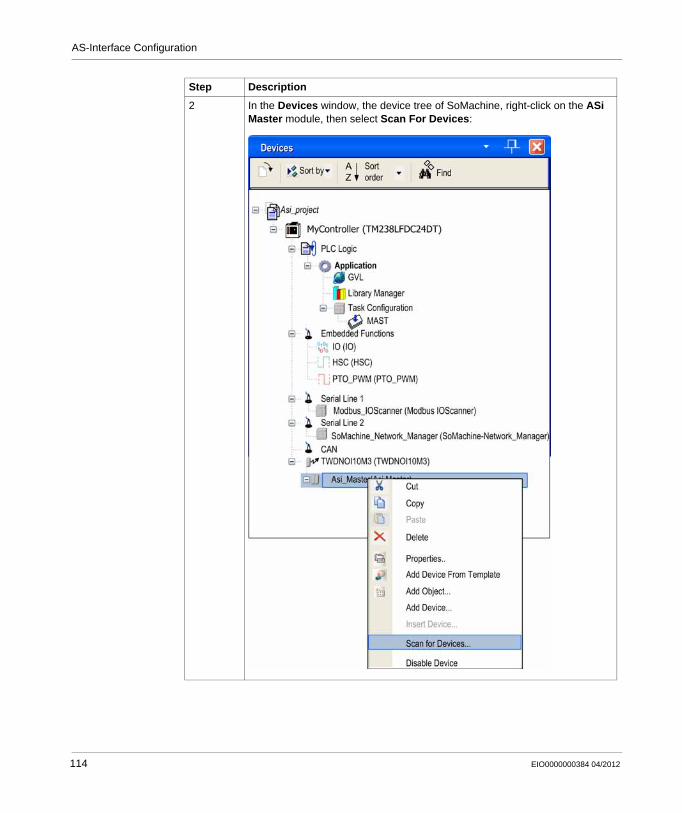
AS-Interface Configuration
2 In the Devices window, the device tree of SoMachine, right-click on the ASi Master module, then select Scan For Devices:
Step Description
114 EIO0000000384 04/2012
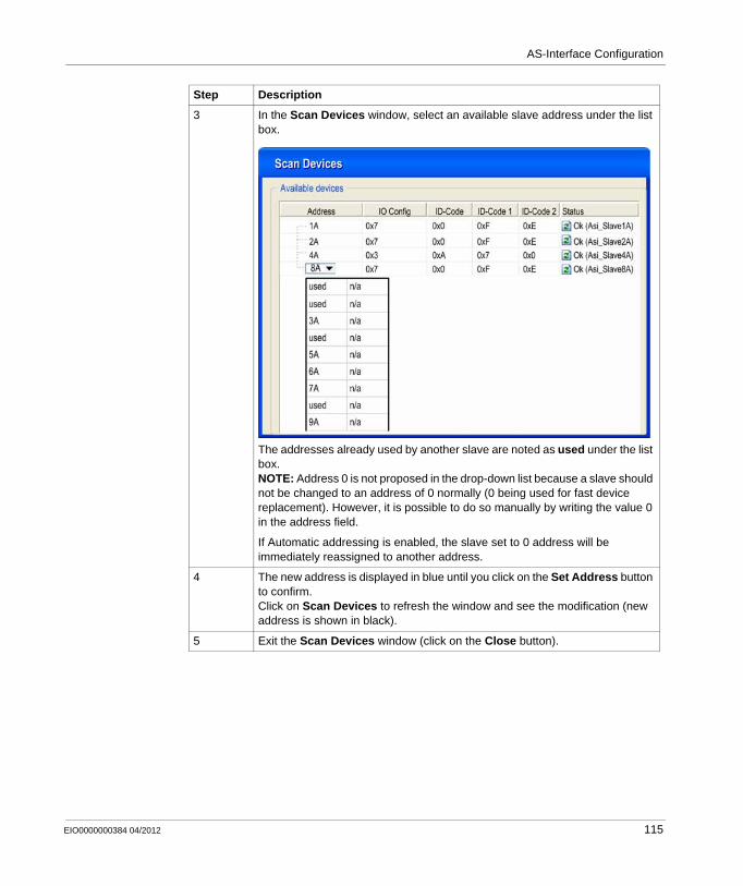
AS-Interface Configuration
3 In the Scan Devices window, select an available slave address under the list box.
The addresses already used by another slave are noted as used under the list box.NOTE: Address 0 is not proposed in the drop-down list because a slave should not be changed to an address of 0 normally (0 being used for fast device replacement). However, it is possible to do so manually by writing the value 0 in the address field.
If Automatic addressing is enabled, the slave set to 0 address will be immediately reassigned to another address.
4 The new address is displayed in blue until you click on the Set Address button to confirm.Click on Scan Devices to refresh the window and see the modification (new address is shown in black).
5 Exit the Scan Devices window (click on the Close button).
Step Description
EIO0000000384 04/2012 115
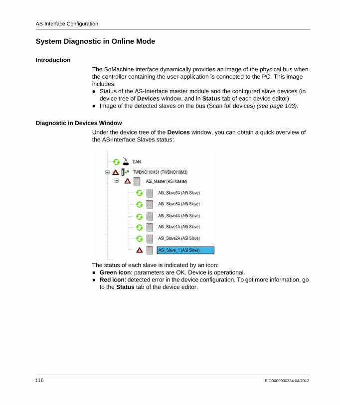
AS-Interface Configuration
System Diagnostic in Online Mode
Introduction
The SoMachine interface dynamically provides an image of the physical bus when the controller containing the user application is connected to the PC. This image includes:
Status of the AS-Interface master module and the configured slave devices (in device tree of Devices window, and in Status tab of each device editor)Image of the detected slaves on the bus (Scan for devices) (see page 103).
Diagnostic in Devices Window
Under the device tree of the Devices window, you can obtain a quick overview of the AS-Interface Slaves status:
The status of each slave is indicated by an icon:Green icon: parameters are OK. Device is operational.Red icon: detected error in the device configuration. To get more information, go to the Status tab of the device editor.
116 EIO0000000384 04/2012
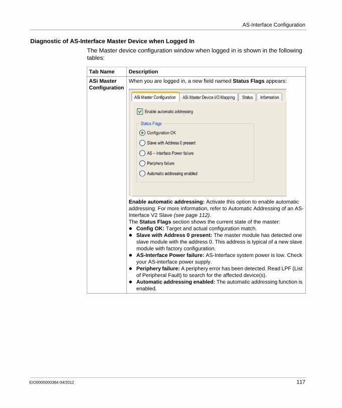
AS-Interface Configuration
Diagnostic of AS-Interface Master Device when Logged In
The Master device configuration window when logged in is shown in the following tables:
Tab Name Description
ASi Master Configuration
When you are logged in, a new field named Status Flags appears:
Enable automatic addressing: Activate this option to enable automatic addressing. For more information, refer to Automatic Addressing of an AS-Interface V2 Slave (see page 112).The Status Flags section shows the current state of the master:
Config OK: Target and actual configuration match.Slave with Address 0 present: The master module has detected one slave module with the address 0. This address is typical of a new slave module with factory configuration.AS-Interface Power failure: AS-Interface system power is low. Check your AS-interface power supply.Periphery failure: A periphery error has been detected. Read LPF (List of Peripheral Fault) to search for the affected device(s).Automatic addressing enabled: The automatic addressing function is enabled.
EIO0000000384 04/2012 117
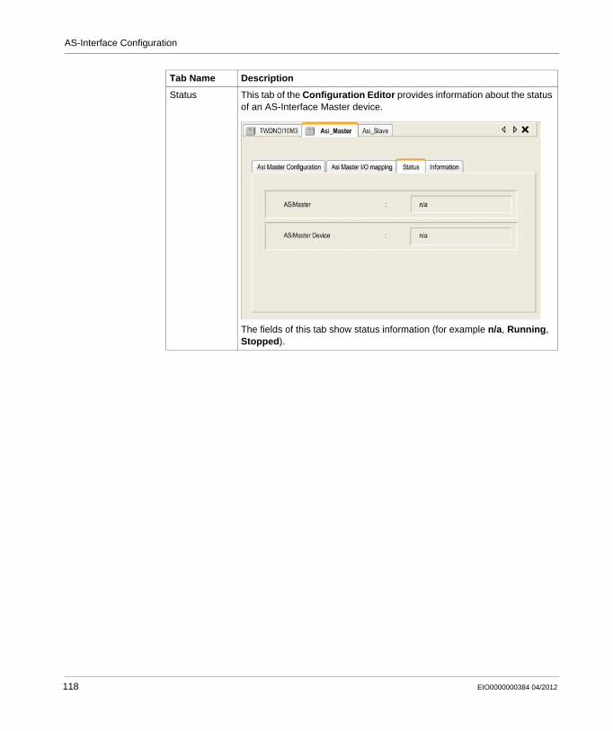
AS-Interface Configuration
Status This tab of the Configuration Editor provides information about the status of an AS-Interface Master device.
The fields of this tab show status information (for example n/a, Running, Stopped).
Tab Name Description
118 EIO0000000384 04/2012
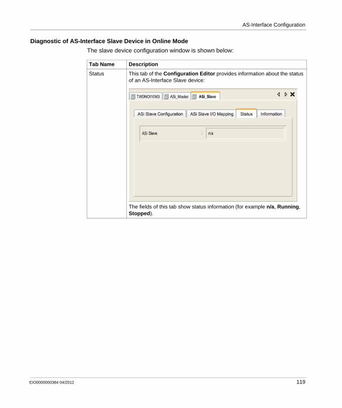
AS-Interface Configuration
Diagnostic of AS-Interface Slave Device in Online Mode
The slave device configuration window is shown below:
Tab Name Description
Status This tab of the Configuration Editor provides information about the status of an AS-Interface Slave device:
The fields of this tab show status information (for example n/a, Running, Stopped).
EIO0000000384 04/2012 119
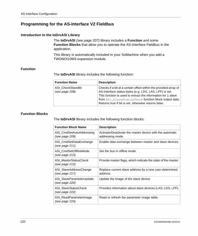
AS-Interface Configuration
Programming for the AS-Interface V2 Fieldbus
Introduction to the IoDrvASI Library
The IoDrvASI (see page 207) library includes a Function and some Function Blocks that allow you to operate the AS-Interface Fieldbus in the application.
This library is automatically included in your SoMachine when you add a TWDNOI10M3 expansion module.
Function
The IoDrvASI library includes the following function:
Function Blocks
The IoDrvASI library includes the following function blocks:
Function Name Description
ASI_CheckSlaveBit (see page 208)
Checks if a bit at a certain offset within the provided array of AS-Interface status bytes (e.g. LDS, LAS, LPF) is set.This function is used to extract the information for 1 slave from ASI_SlaveStatusCheck function block output data.Returns true if bit is set, otherwise returns false.
Function Block Name Description
ASI_CmdSetAutoAddressing (see page 209)
Activate/Deactivate the master device with the automatic addressing mode.
ASI_CmdSetDataExchange (see page 211)
Enable data exchange between master and slave devices.
ASI_CmdSetOfflineMode (see page 213)
Set the bus in offline mode.
ASI_MasterStatusCheck (see page 215)
Provide master flags, which indicate the state of the master.
ASI_SlaveAddressChange (see page 217)
Replace current slave address by a new user-determined address.
ASI_SlaveParameterUpdate (see page 220)
Update the image of the slave device.
ASI_SlaveStatusCheck (see page 222)
Provides information about slave devices (LAS, LDS, LPF).
ASI_ReadParameterImage (see page 224)
Read or refresh the parameter image table.
120 EIO0000000384 04/2012
AS-Interface Configuration
Configuration of a Replaced AS-Interface V2 Slave
Automatic Configuration
When a slave must be replaced, it can be automatically replaced with a slave with the same AS-Interface profile.
This happens without the AS-Interface V2 Fieldbus having to stop, and without requiring any manipulation if the configuration mode’s Automatic addressing utility is active (see page 112).
The replacement slave must initial have the address 0 (a new slave is usually factory set with a default address of 0), and the same profile as the slave it will replace. It will automatically assume the address of the replaced slave once installed, and will then be inserted into the list of detected slaves (LDS) and the list of active slaves (LAS).
Manual Configuration
Alternative options without automatic addressing are available:You can configure the replacement slave with the same address as the slave it will replace using the pocket programmer. As previously noted, the replacement must have the same product reference number and the same profile and sub-profile of the slave to replace. It is thus automatically inserted into the list of detected slaves (LDS) and into the list of active slaves (LAS). This feature is available only if one, and not more than one, slave is inoperative.Change the address using the Scan For Devices window (see page 100).
EIO0000000384 04/2012 121

AS-Interface Configuration
122 EIO0000000384 04/2012
EIO0000000384 04/2012
13
Modicon M238 Logic Controller
Serial Line Configuration
EIO0000000384 04/2012
Serial Line Configuration
Introduction
This chapter describes how to configue the serial line communication of the Modicon M238 Logic Controller.
What’s in this Chapter?
This chapter contains the following topics:
Topic Page
Serial Lines Configuration 124
ASCII Manager 128
SoMachine Network Manager 131
Modbus IOScanner 133
Modbus Manager 143
Adding a Modem to a Manager 148
123
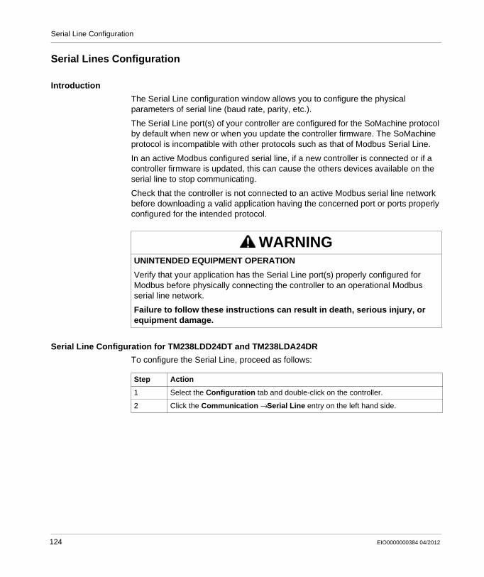
Serial Line Configuration
Serial Lines Configuration
Introduction
The Serial Line configuration window allows you to configure the physical parameters of serial line (baud rate, parity, etc.).
The Serial Line port(s) of your controller are configured for the SoMachine protocol by default when new or when you update the controller firmware. The SoMachine protocol is incompatible with other protocols such as that of Modbus Serial Line.
In an active Modbus configured serial line, if a new controller is connected or if a controller firmware is updated, this can cause the others devices available on the serial line to stop communicating.
Check that the controller is not connected to an active Modbus serial line network before downloading a valid application having the concerned port or ports properly configured for the intended protocol.
Serial Line Configuration for TM238LDD24DT and TM238LDA24DR
To configure the Serial Line, proceed as follows:
WARNINGUNINTENDED EQUIPMENT OPERATION
Verify that your application has the Serial Line port(s) properly configured for Modbus before physically connecting the controller to an operational Modbus serial line network.
Failure to follow these instructions can result in death, serious injury, or equipment damage.
Step Action
1 Select the Configuration tab and double-click on the controller.
2 Click the Communication → Serial Line entry on the left hand side.
124 EIO0000000384 04/2012
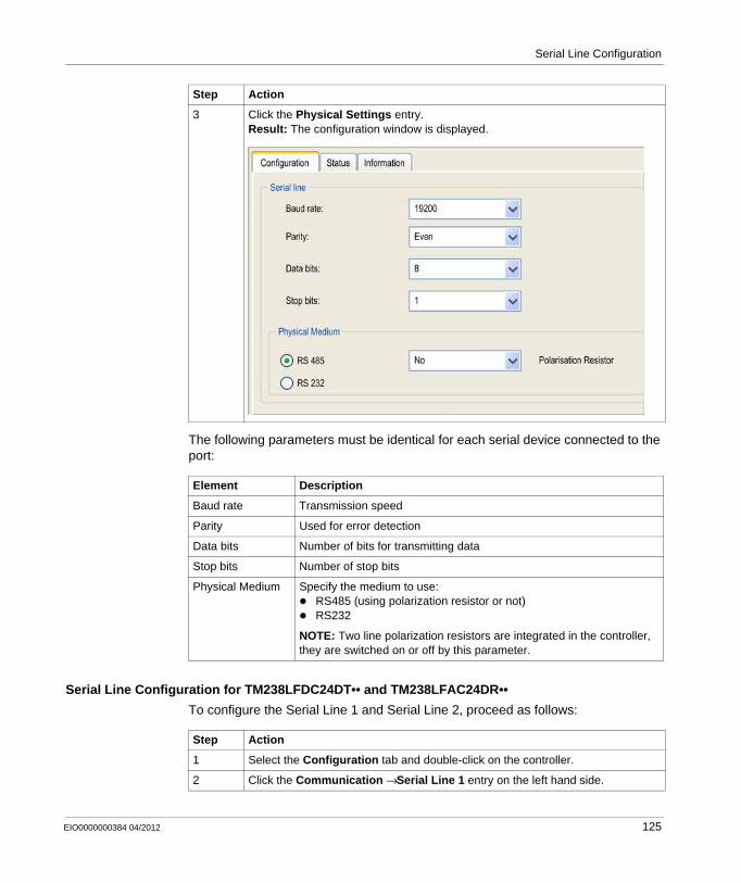
Serial Line Configuration
The following parameters must be identical for each serial device connected to the port:
Serial Line Configuration for TM238LFDC24DT•• and TM238LFAC24DR••
To configure the Serial Line 1 and Serial Line 2, proceed as follows:
3 Click the Physical Settings entry.Result: The configuration window is displayed.
Element Description
Baud rate Transmission speed
Parity Used for error detection
Data bits Number of bits for transmitting data
Stop bits Number of stop bits
Physical Medium Specify the medium to use:RS485 (using polarization resistor or not)RS232
NOTE: Two line polarization resistors are integrated in the controller, they are switched on or off by this parameter.
Step Action
Step Action
1 Select the Configuration tab and double-click on the controller.
2 Click the Communication → Serial Line 1 entry on the left hand side.
EIO0000000384 04/2012 125
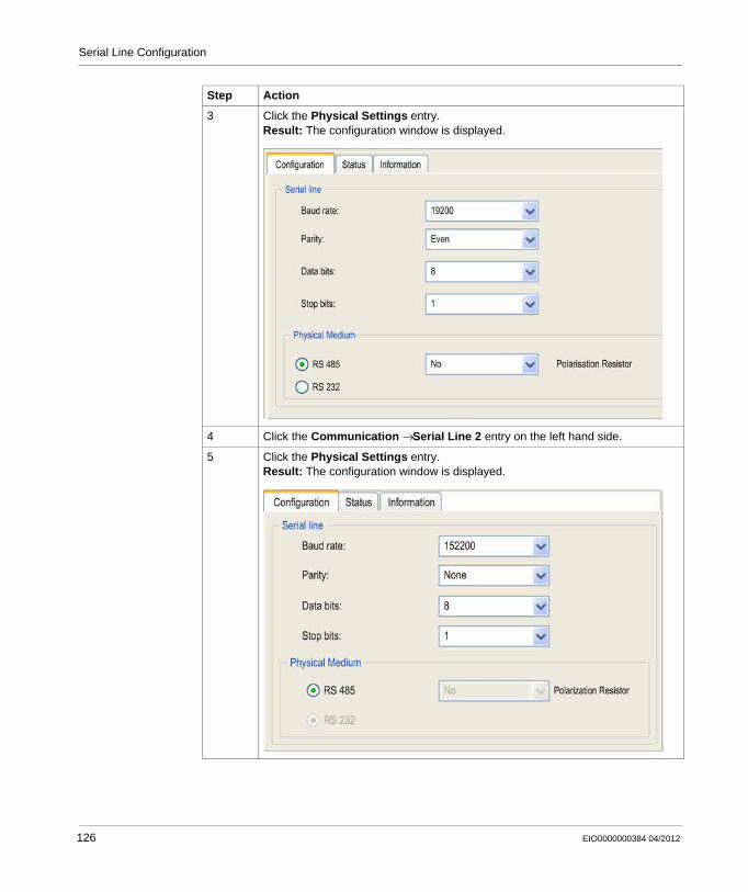
Serial Line Configuration
3 Click the Physical Settings entry.Result: The configuration window is displayed.
4 Click the Communication → Serial Line 2 entry on the left hand side.
5 Click the Physical Settings entry.Result: The configuration window is displayed.
Step Action
126 EIO0000000384 04/2012
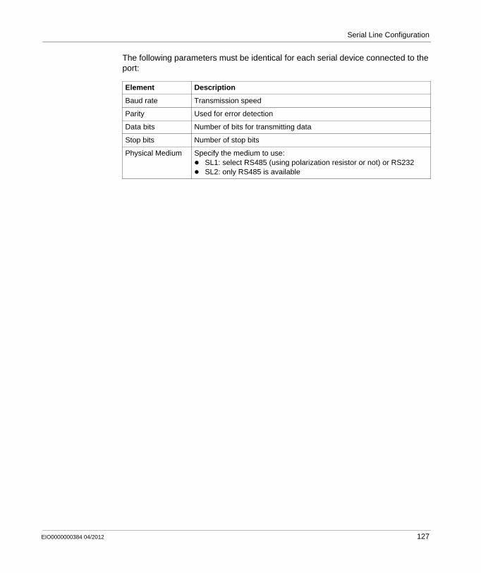
Serial Line Configuration
The following parameters must be identical for each serial device connected to the port:
Element Description
Baud rate Transmission speed
Parity Used for error detection
Data bits Number of bits for transmitting data
Stop bits Number of stop bits
Physical Medium Specify the medium to use:SL1: select RS485 (using polarization resistor or not) or RS232SL2: only RS485 is available
EIO0000000384 04/2012 127
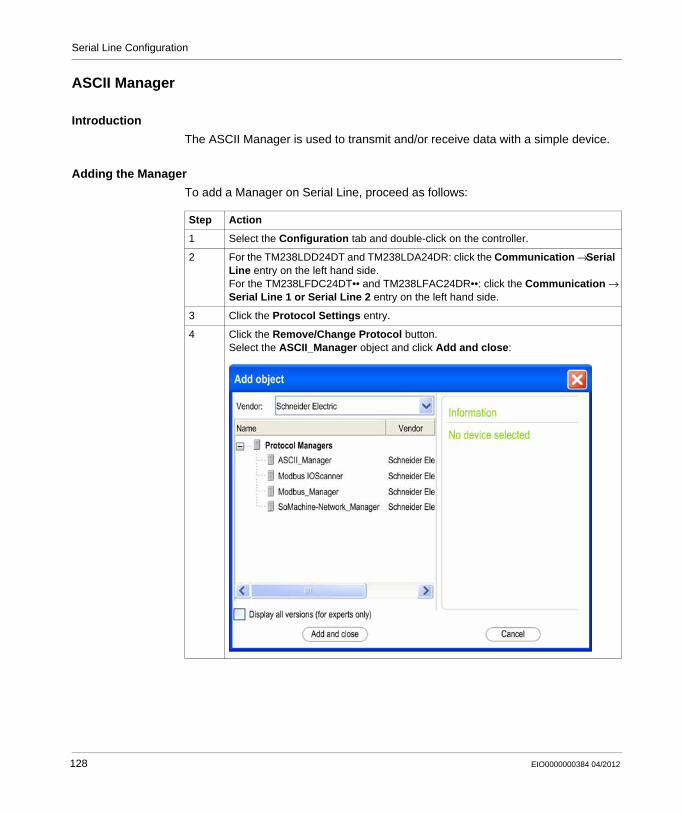
Serial Line Configuration
ASCII Manager
Introduction
The ASCII Manager is used to transmit and/or receive data with a simple device.
Adding the Manager
To add a Manager on Serial Line, proceed as follows:
Step Action
1 Select the Configuration tab and double-click on the controller.
2 For the TM238LDD24DT and TM238LDA24DR: click the Communication → Serial Line entry on the left hand side.For the TM238LFDC24DT•• and TM238LFAC24DR••: click the Communication → Serial Line 1 or Serial Line 2 entry on the left hand side.
3 Click the Protocol Settings entry.
4 Click the Remove/Change Protocol button.Select the ASCII_Manager object and click Add and close:
128 EIO0000000384 04/2012
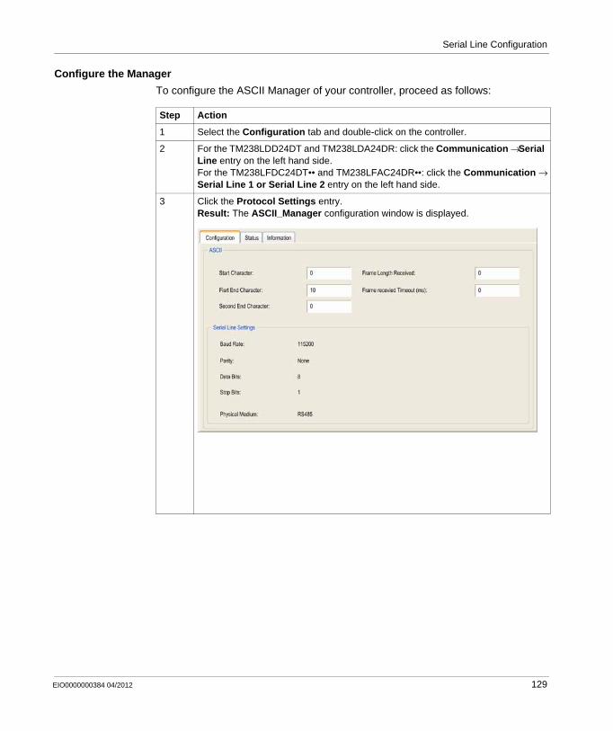
Serial Line Configuration
Configure the Manager
To configure the ASCII Manager of your controller, proceed as follows:
Step Action
1 Select the Configuration tab and double-click on the controller.
2 For the TM238LDD24DT and TM238LDA24DR: click the Communication → Serial Line entry on the left hand side.For the TM238LFDC24DT•• and TM238LFAC24DR••: click the Communication → Serial Line 1 or Serial Line 2 entry on the left hand side.
3 Click the Protocol Settings entry.Result: The ASCII_Manager configuration window is displayed.
EIO0000000384 04/2012 129
Serial Line Configuration
Set the parameters as described in the following table:
NOTE: In the case of using several frame termination conditions, the first condition to be TRUE will terminate the exchange.
Adding a Modem
For more details about how to add a Modem to the ASCII Manager, refer to the Adding Modem to a Manager section (see page 148).
Parameter Description
Start Character If 0, no start character is used in the frame. Otherwise, in Receiving Mode the corresponding character in ASCII is used to detect the beginning of a frame. In Sending Mode, this character is added at the beginning of the frame.
First End Character
If 0, no first end character is used in the frame. Otherwise, in Receiving Mode the corresponding character in ASCII is used to detect the end of a frame. In Sending Mode, this character is added at the end of the frame.
Second End Character
If 0, no second end character is used in the frame. Otherwise, in Receiving Mode the corresponding character in ASCII is used to detect the end of a frame. In Sending Mode, this character is added at the end of the frame.
Frame Length Received
If 0, this parameter is not used. This parameter allows the system to conclude an end of frame at reception, when the controller received the specified number of characters.NOTE: This parameter cannot be used simultaneously with Frame Received Timeout (ms).
Frame Received Timeout (ms)
If 0, this parameter is not used. This parameter allows the system to conclude the end of frame at reception after a silence of the specified number of ms.
Serial Line Settings
Parameters specified in the Serial Line configuration window (see page 124).
130 EIO0000000384 04/2012
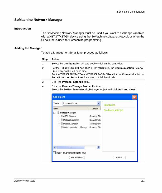
Serial Line Configuration
SoMachine Network Manager
Introduction
The SoMachine Network Manager must be used if you want to exchange variables with a XBTGT/XBTGK device using the SoMachine software protocol, or when the Serial Line is used for SoMachine programming.
Adding the Manager
To add a Manager on Serial Line, proceed as follows:
Step Action
1 Select the Configuration tab and double-click on the controller.
2 For the TM238LDD24DT and TM238LDA24DR: click the Communication → Serial Line entry on the left hand side.For the TM238LFDC24DT•• and TM238LFAC24DR••: click the Communication → Serial Line 1 or Serial Line 2 entry on the left hand side.
3 Click the Protocol Settings entry.
4 Click the Remove/Change Protocol button.Select the SoMachine-Network_Manager object and click Add and close:
EIO0000000384 04/2012 131
Serial Line Configuration
Configure the Manager
There is no configuration for SoMachine Network Manager.
Adding a Modem
For more details about how to add a Modem to the SoMachine Network Manager, refer to the Adding Modem to a Manager section (see page 148).
132 EIO0000000384 04/2012
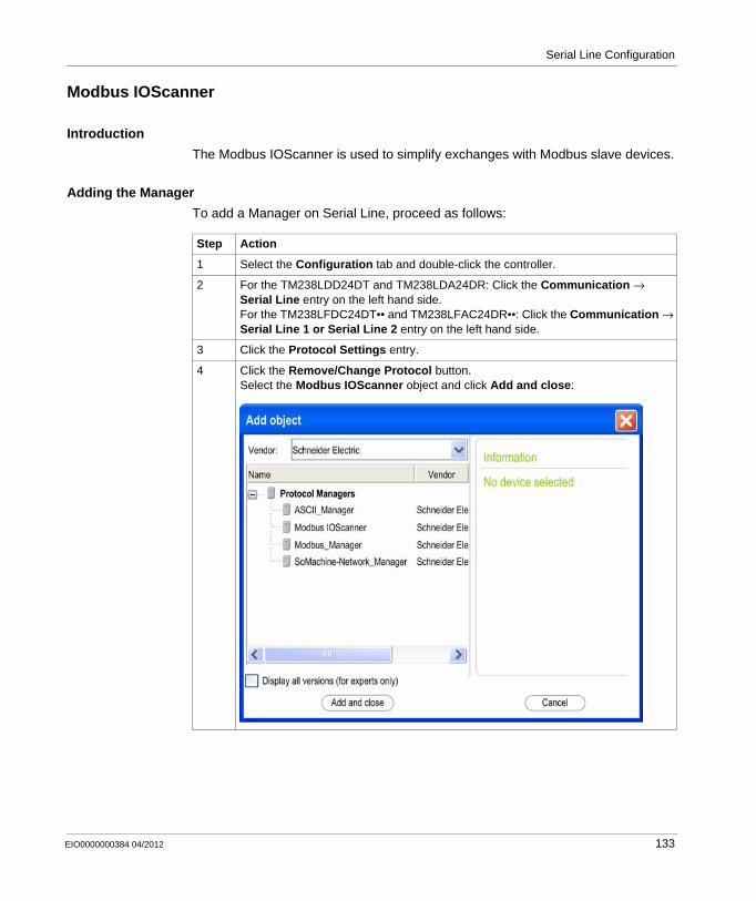
Serial Line Configuration
Modbus IOScanner
Introduction
The Modbus IOScanner is used to simplify exchanges with Modbus slave devices.
Adding the Manager
To add a Manager on Serial Line, proceed as follows:
Step Action
1 Select the Configuration tab and double-click the controller.
2 For the TM238LDD24DT and TM238LDA24DR: Click the Communication → Serial Line entry on the left hand side.For the TM238LFDC24DT•• and TM238LFAC24DR••: Click the Communication → Serial Line 1 or Serial Line 2 entry on the left hand side.
3 Click the Protocol Settings entry.
4 Click the Remove/Change Protocol button.Select the Modbus IOScanner object and click Add and close:
EIO0000000384 04/2012 133
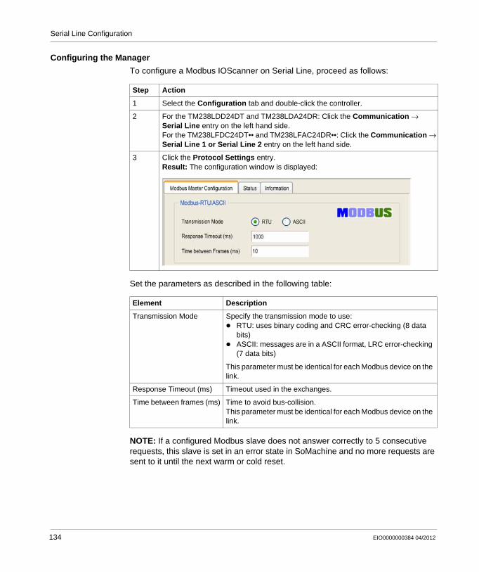
Serial Line Configuration
Configuring the Manager
To configure a Modbus IOScanner on Serial Line, proceed as follows:
Set the parameters as described in the following table:
NOTE: If a configured Modbus slave does not answer correctly to 5 consecutive requests, this slave is set in an error state in SoMachine and no more requests are sent to it until the next warm or cold reset.
Step Action
1 Select the Configuration tab and double-click the controller.
2 For the TM238LDD24DT and TM238LDA24DR: Click the Communication → Serial Line entry on the left hand side.For the TM238LFDC24DT•• and TM238LFAC24DR••: Click the Communication → Serial Line 1 or Serial Line 2 entry on the left hand side.
3 Click the Protocol Settings entry.Result: The configuration window is displayed:
Element Description
Transmission Mode Specify the transmission mode to use:RTU: uses binary coding and CRC error-checking (8 data bits)ASCII: messages are in a ASCII format, LRC error-checking (7 data bits)
This parameter must be identical for each Modbus device on the link.
Response Timeout (ms) Timeout used in the exchanges.
Time between frames (ms) Time to avoid bus-collision.This parameter must be identical for each Modbus device on the link.
134 EIO0000000384 04/2012
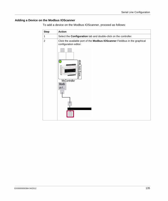
Serial Line Configuration
Adding a Device on the Modbus IOScanner
To add a device on the Modbus IOScanner, proceed as follows:
Step Action
1 Select the Configuration tab and double-click on the controller.
2 Click the available port of the Modbus IOScanner Fieldbus in the graphical configuration editor:
EIO0000000384 04/2012 135
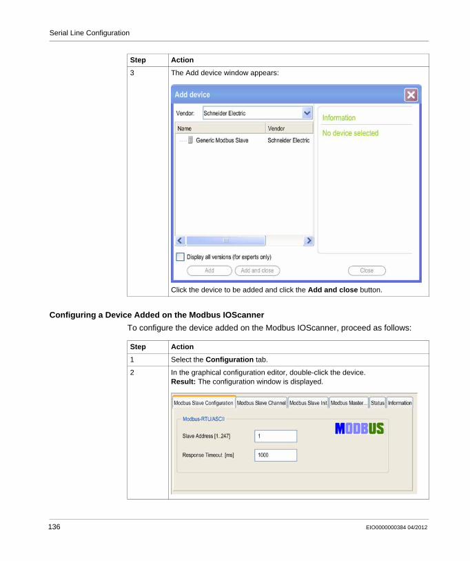
Serial Line Configuration
Configuring a Device Added on the Modbus IOScanner
To configure the device added on the Modbus IOScanner, proceed as follows:
3 The Add device window appears:
Click the device to be added and click the Add and close button.
Step Action
Step Action
1 Select the Configuration tab.
2 In the graphical configuration editor, double-click the device.Result: The configuration window is displayed.
136 EIO0000000384 04/2012
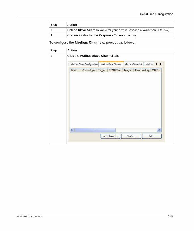
Serial Line Configuration
To configure the Modbus Channels, proceed as follows:
3 Enter a Slave Address value for your device (choose a value from 1 to 247).
4 Choose a value for the Response Timeout (in ms).
Step Action
1 Click the Modbus Slave Channel tab.
Step Action
EIO0000000384 04/2012 137
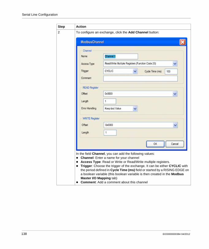
Serial Line Configuration
2 To configure an exchange, click the Add Channel button:
In the field Channel, you can add the following values:Channel: Enter a name for your channelAccess Type: Read or Write or Read/Write multiple registers.Trigger: Choose the trigger of the exchange. It can be either CYCLIC with the period defined in Cycle Time (ms) field or started by a RISING EDGE on a boolean variable (this boolean variable is then created in the Modbus Master I/O Mapping tab)Comment: Add a comment about this channel
Step Action
138 EIO0000000384 04/2012
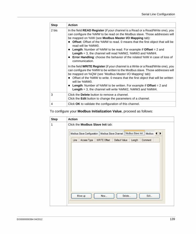
Serial Line Configuration
To configure your Modbus Initialization Value, proceed as follows:
2 bis In the field READ Register (if your channel is a Read or a Read/Write one), you can configure the %MW to be read on the Modbus slave. Those addresses will be mapped on %IW (see Modbus Master I/O Mapping tab):
Offset: Offset of the %MW to read. 0 means that the first object that will be read will be %MW0.Length: Number of %MW to be read. For example if Offset = 2 and Length = 3, the channel will read %MW2, %MW3 and %MW4.Error Handling: choose the behavior of the related %IW in case of loss of communication.
In the field WRITE Register (if your channel is a Write or a Read/Write one), you can configure the %MW to be written to the Modbus slave. Those addresses will be mapped on %QW (see ’Modbus Master I/O Mapping’ tab):
Offset of the %MW to write. 0 means that the first object that will be written will be %MW0.Length: Number of %MW to be written. For example if Offset = 2 and Length = 3, the channel will write %MW2, %MW3 and %MW4.
3 Click the Delete button to remove a channel.Click the Edit button to change the parameters of a channel.
4 Click OK to validate the configuration of this channel.
Step Action
1 Click the Modbus Slave Init tab:
Step Action
EIO0000000384 04/2012 139
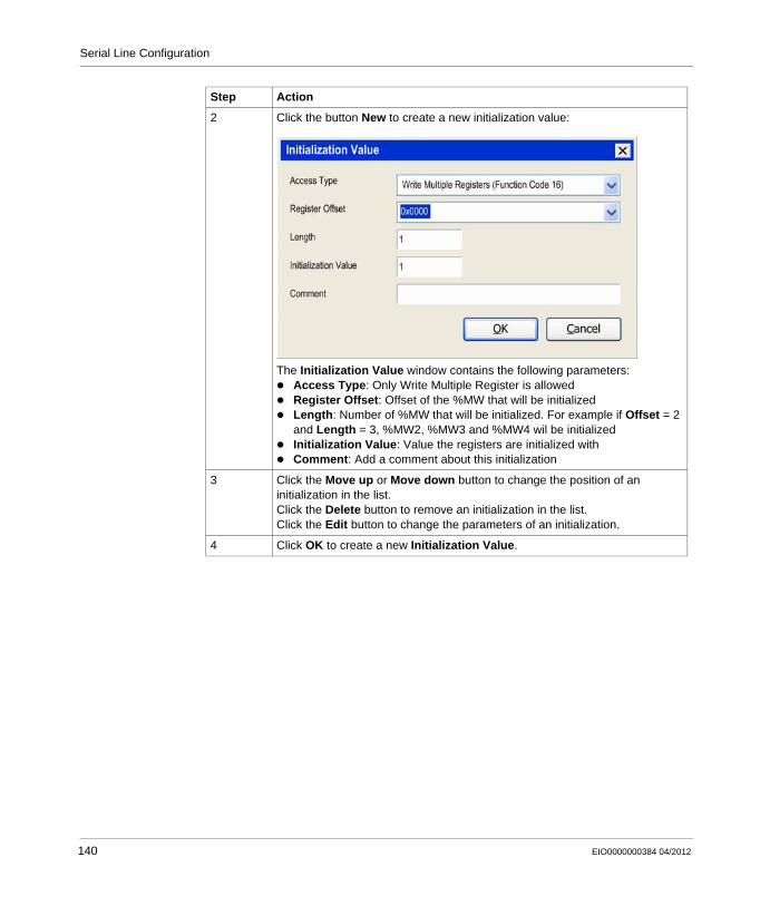
Serial Line Configuration
2 Click the button New to create a new initialization value:
The Initialization Value window contains the following parameters:Access Type: Only Write Multiple Register is allowedRegister Offset: Offset of the %MW that will be initializedLength: Number of %MW that will be initialized. For example if Offset = 2 and Length = 3, %MW2, %MW3 and %MW4 wil be initializedInitialization Value: Value the registers are initialized withComment: Add a comment about this initialization
3 Click the Move up or Move down button to change the position of an initialization in the list.Click the Delete button to remove an initialization in the list.Click the Edit button to change the parameters of an initialization.
4 Click OK to create a new Initialization Value.
Step Action
140 EIO0000000384 04/2012
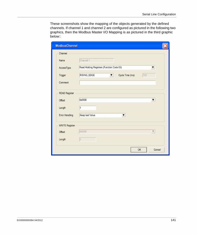
Serial Line Configuration
These screenshots show the mapping of the objects generated by the defined channels. If channel 1 and channel 2 are configured as pictured in the following two graphics, then the Modbus Master I/O Mapping is as pictured in the third graphic below::
EIO0000000384 04/2012 141
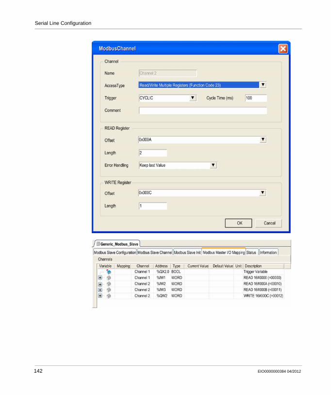
Serial Line Configuration
142 EIO0000000384 04/2012
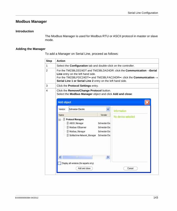
Serial Line Configuration
Modbus Manager
Introduction
The Modbus Manager is used for Modbus RTU or ASCII protocol in master or slave mode.
Adding the Manager
To add a Manager on Serial Line, proceed as follows:
Step Action
1 Select the Configuration tab and double-click on the controller.
2 For the TM238LDD24DT and TM238LDA24DR: click the Communication → Serial Line entry on the left hand side.For the TM238LFDC24DT•• and TM238LFAC24DR••: click the Communication → Serial Line 1 or Serial Line 2 entry on the left hand side.
3 Click the Protocol Settings entry.
4 Click the Remove/Change Protocol button.Select the Modbus Manager object and click Add and close:
EIO0000000384 04/2012 143
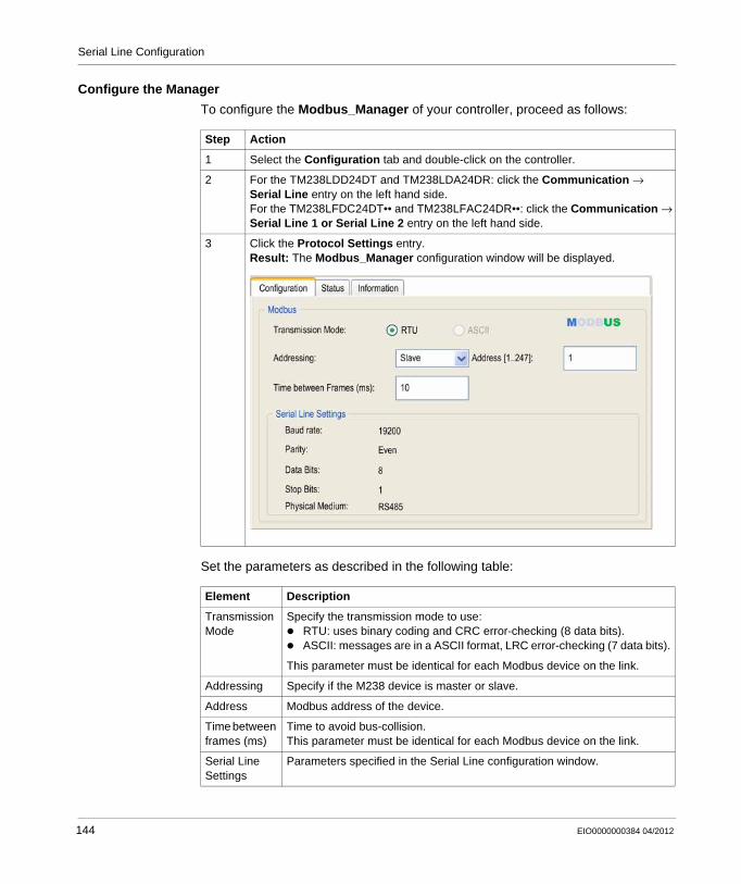
Serial Line Configuration
Configure the Manager
To configure the Modbus_Manager of your controller, proceed as follows:
Set the parameters as described in the following table:
Step Action
1 Select the Configuration tab and double-click on the controller.
2 For the TM238LDD24DT and TM238LDA24DR: click the Communication → Serial Line entry on the left hand side.For the TM238LFDC24DT•• and TM238LFAC24DR••: click the Communication → Serial Line 1 or Serial Line 2 entry on the left hand side.
3 Click the Protocol Settings entry.Result: The Modbus_Manager configuration window will be displayed.
Element Description
Transmission Mode
Specify the transmission mode to use:RTU: uses binary coding and CRC error-checking (8 data bits).ASCII: messages are in a ASCII format, LRC error-checking (7 data bits).
This parameter must be identical for each Modbus device on the link.
Addressing Specify if the M238 device is master or slave.
Address Modbus address of the device.
Time between frames (ms)
Time to avoid bus-collision.This parameter must be identical for each Modbus device on the link.
Serial Line Settings
Parameters specified in the Serial Line configuration window.
144 EIO0000000384 04/2012
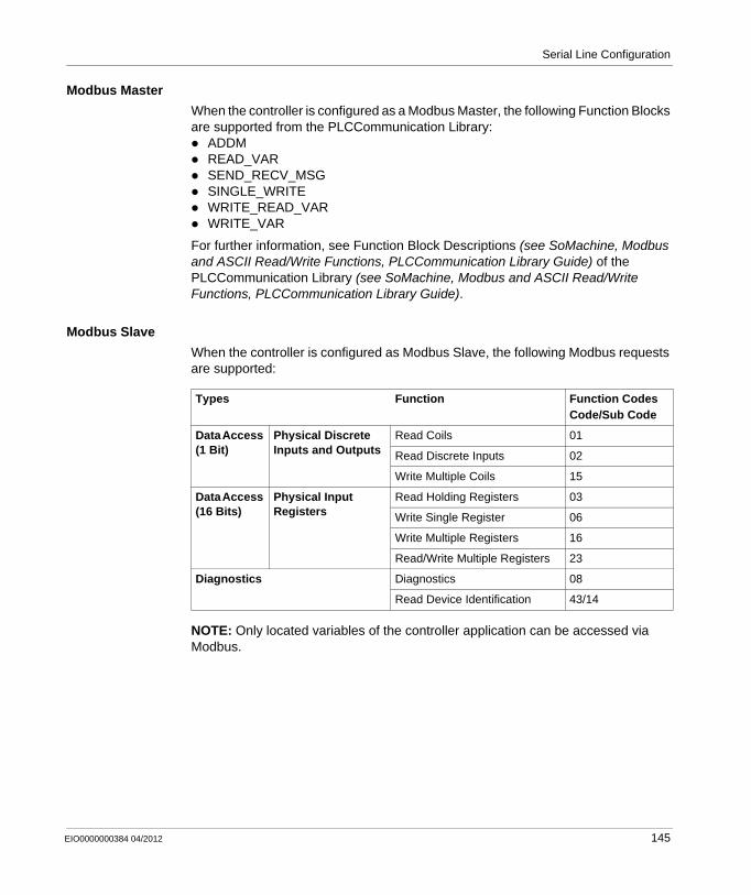
Serial Line Configuration
Modbus Master
When the controller is configured as a Modbus Master, the following Function Blocks are supported from the PLCCommunication Library:
ADDMREAD_VARSEND_RECV_MSGSINGLE_WRITEWRITE_READ_VARWRITE_VAR
For further information, see Function Block Descriptions (see SoMachine, Modbus and ASCII Read/Write Functions, PLCCommunication Library Guide) of the PLCCommunication Library (see SoMachine, Modbus and ASCII Read/Write Functions, PLCCommunication Library Guide).
Modbus Slave
When the controller is configured as Modbus Slave, the following Modbus requests are supported:
NOTE: Only located variables of the controller application can be accessed via Modbus.
Types Function Function CodesCode/Sub Code
Data Access (1 Bit)
Physical Discrete Inputs and Outputs
Read Coils 01
Read Discrete Inputs 02
Write Multiple Coils 15
Data Access (16 Bits)
Physical Input Registers
Read Holding Registers 03
Write Single Register 06
Write Multiple Registers 16
Read/Write Multiple Registers 23
Diagnostics Diagnostics 08
Read Device Identification 43/14
EIO0000000384 04/2012 145
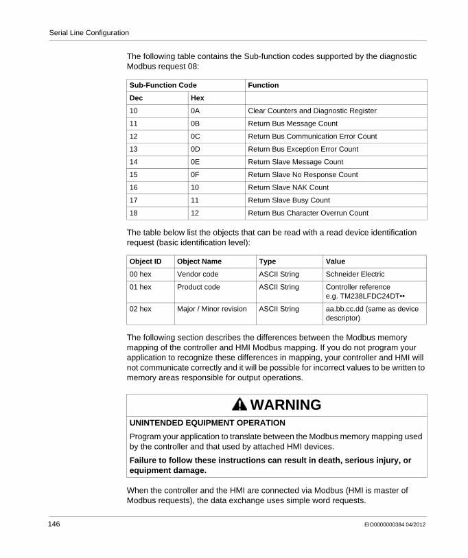
Serial Line Configuration
The following table contains the Sub-function codes supported by the diagnostic Modbus request 08:
The table below list the objects that can be read with a read device identification request (basic identification level):
The following section describes the differences between the Modbus memory mapping of the controller and HMI Modbus mapping. If you do not program your application to recognize these differences in mapping, your controller and HMI will not communicate correctly and it will be possible for incorrect values to be written to memory areas responsible for output operations.
When the controller and the HMI are connected via Modbus (HMI is master of Modbus requests), the data exchange uses simple word requests.
Sub-Function Code Function
Dec Hex
10 0A Clear Counters and Diagnostic Register
11 0B Return Bus Message Count
12 0C Return Bus Communication Error Count
13 0D Return Bus Exception Error Count
14 0E Return Slave Message Count
15 0F Return Slave No Response Count
16 10 Return Slave NAK Count
17 11 Return Slave Busy Count
18 12 Return Bus Character Overrun Count
Object ID Object Name Type Value
00 hex Vendor code ASCII String Schneider Electric
01 hex Product code ASCII String Controller referencee.g. TM238LFDC24DT••
02 hex Major / Minor revision ASCII String aa.bb.cc.dd (same as device descriptor)
WARNINGUNINTENDED EQUIPMENT OPERATION
Program your application to translate between the Modbus memory mapping used by the controller and that used by attached HMI devices.
Failure to follow these instructions can result in death, serious injury, or equipment damage.
146 EIO0000000384 04/2012
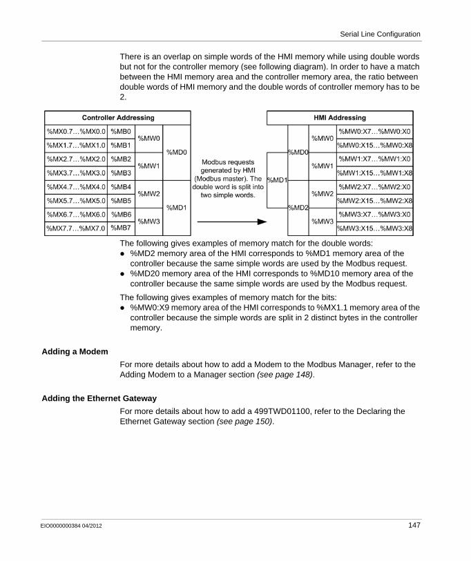
Serial Line Configuration
There is an overlap on simple words of the HMI memory while using double words but not for the controller memory (see following diagram). In order to have a match between the HMI memory area and the controller memory area, the ratio between double words of HMI memory and the double words of controller memory has to be 2.
The following gives examples of memory match for the double words:%MD2 memory area of the HMI corresponds to %MD1 memory area of the controller because the same simple words are used by the Modbus request.%MD20 memory area of the HMI corresponds to %MD10 memory area of the controller because the same simple words are used by the Modbus request.
The following gives examples of memory match for the bits:%MW0:X9 memory area of the HMI corresponds to %MX1.1 memory area of the controller because the simple words are split in 2 distinct bytes in the controller memory.
Adding a Modem
For more details about how to add a Modem to the Modbus Manager, refer to the Adding Modem to a Manager section (see page 148).
Adding the Ethernet Gateway
For more details about how to add a 499TWD01100, refer to the Declaring the Ethernet Gateway section (see page 150).
EIO0000000384 04/2012 147
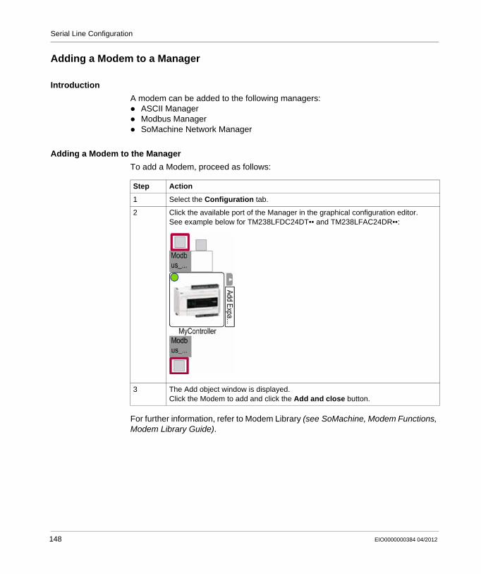
Serial Line Configuration
Adding a Modem to a Manager
Introduction
A modem can be added to the following managers: ASCII ManagerModbus ManagerSoMachine Network Manager
Adding a Modem to the Manager
To add a Modem, proceed as follows:
For further information, refer to Modem Library (see SoMachine, Modem Functions, Modem Library Guide).
Step Action
1 Select the Configuration tab.
2 Click the available port of the Manager in the graphical configuration editor.See example below for TM238LFDC24DT•• and TM238LFAC24DR••:
3 The Add object window is displayed.Click the Modem to add and click the Add and close button.
148 EIO0000000384 04/2012
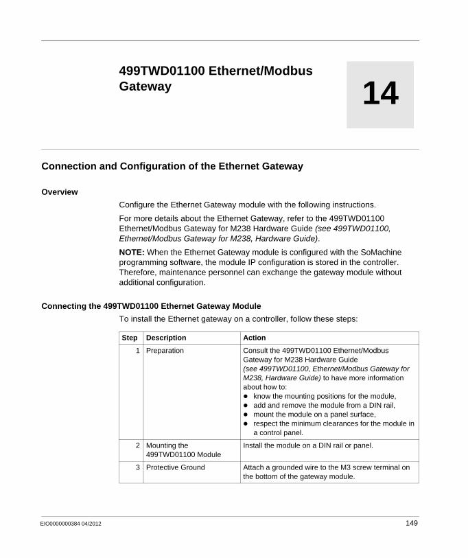
EIO0000000384 04/2012
14
Modicon M238 Logic Controller
Ethernet/Modbus Gateway
EIO0000000384 04/2012
499TWD01100 Ethernet/Modbus Gateway
Connection and Configuration of the Ethernet Gateway
Overview
Configure the Ethernet Gateway module with the following instructions.
For more details about the Ethernet Gateway, refer to the 499TWD01100 Ethernet/Modbus Gateway for M238 Hardware Guide (see 499TWD01100, Ethernet/Modbus Gateway for M238, Hardware Guide).
NOTE: When the Ethernet Gateway module is configured with the SoMachine programming software, the module IP configuration is stored in the controller. Therefore, maintenance personnel can exchange the gateway module without additional configuration.
Connecting the 499TWD01100 Ethernet Gateway Module
To install the Ethernet gateway on a controller, follow these steps:
Step Description Action
1 Preparation Consult the 499TWD01100 Ethernet/Modbus Gateway for M238 Hardware Guide (see 499TWD01100, Ethernet/Modbus Gateway for M238, Hardware Guide) to have more information about how to:
know the mounting positions for the module,add and remove the module from a DIN rail,mount the module on a panel surface,respect the minimum clearances for the module in a control panel.
2 Mounting the 499TWD01100 Module
Install the module on a DIN rail or panel.
3 Protective Ground Attach a grounded wire to the M3 screw terminal on the bottom of the gateway module.
149
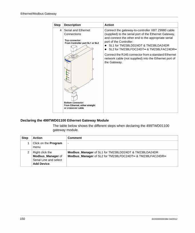
Ethernet/Modbus Gateway
Declaring the 499TWD01100 Ethernet Gateway Module
The table below shows the different steps when declaring the 499TWD01100 gateway module.
4 Serial and Ethernet Connections
Connect the gateway-to-controller XBT Z9980 cable (supplied) to the serial port of the Ethernet Gateway, and connect the other end to the appropriate serial port of the Controller:
SL1 for TM238LDD24DT & TM238LDA24DRSL2 for TM238LFDC24DT•• & TM238LFAC24DR••
Connect the RJ45 connector from a standard Ethernet network cable (not supplied) into the Ethernet port of the Gateway.
Step Description Action
Step Action Comment
1 Click on the Program menu
-
2 Right click the Modbus_Manager of Serial Line and select Add Device.
Modbus_Manager of SL1 for TM238LDD24DT & TM238LDA24DRModbus_Manager of SL2 for TM238LFDC24DT•• & TM238LFAC24DR••
150 EIO0000000384 04/2012
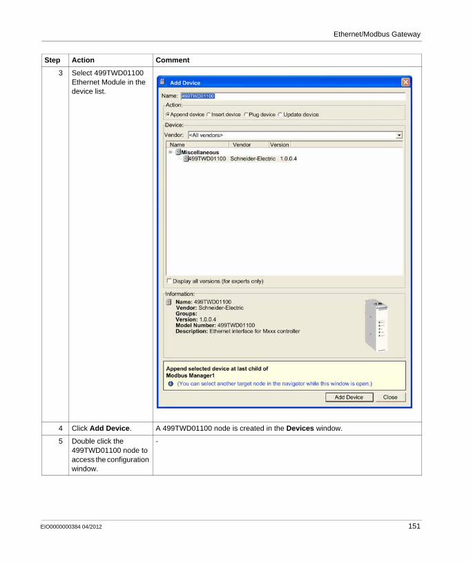
Ethernet/Modbus Gateway
3 Select 499TWD01100 Ethernet Module in the device list.
4 Click Add Device. A 499TWD01100 node is created in the Devices window.
5 Double click the 499TWD01100 node to access the configuration window.
-
Step Action Comment
EIO0000000384 04/2012 151
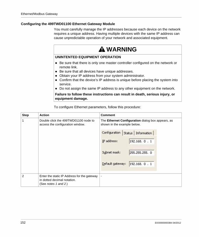
Ethernet/Modbus Gateway
Configuring the 499TWD01100 Ethernet Gateway Module
You must carefully manage the IP addresses because each device on the network requires a unique address. Having multiple devices with the same IP address can cause unpredictable operation of your network and associated equipment.
To configure Ethernet parameters, follow this procedure:
WARNINGUNINTENTED EQUIPMENT OPERATION
Be sure that there is only one master controller configured on the network or remote link.Be sure that all devices have unique addresses.Obtain your IP address from your system administrator.Confirm that the device’s IP address is unique before placing the system into service.Do not assign the same IP address to any other equipment on the network.
Failure to follow these instructions can result in death, serious injury, or equipment damage.
Step Action Comment
1 Double click the 499TWD01100 node to access the configuration window.
The Ethernet Configuration dialog box appears, as shown in the example below.
2 Enter the static IP Address for the gateway in dotted decimal notation. (See notes 1 and 2.)
-
152 EIO0000000384 04/2012
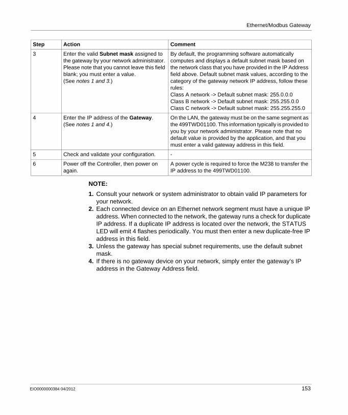
Ethernet/Modbus Gateway
NOTE:
1. Consult your network or system administrator to obtain valid IP parameters for your network.
2. Each connected device on an Ethernet network segment must have a unique IP address. When connected to the network, the gateway runs a check for duplicate IP address. If a duplicate IP address is located over the network, the STATUS LED will emit 4 flashes periodically. You must then enter a new duplicate-free IP address in this field.
3. Unless the gateway has special subnet requirements, use the default subnet mask.
4. If there is no gateway device on your network, simply enter the gateway’s IP address in the Gateway Address field.
3 Enter the valid Subnet mask assigned to the gateway by your network administrator. Please note that you cannot leave this field blank; you must enter a value.(See notes 1 and 3.)
By default, the programming software automatically computes and displays a default subnet mask based on the network class that you have provided in the IP Address field above. Default subnet mask values, according to the category of the gateway network IP address, follow these rules:Class A network -> Default subnet mask: 255.0.0.0Class B network -> Default subnet mask: 255.255.0.0Class C network -> Default subnet mask: 255.255.255.0
4 Enter the IP address of the Gateway.(See notes 1 and 4.)
On the LAN, the gateway must be on the same segment as the 499TWD01100. This information typically is provided to you by your network administrator. Please note that no default value is provided by the application, and that you must enter a valid gateway address in this field.
5 Check and validate your configuration. -
6 Power off the Controller, then power on again.
A power cycle is required to force the M238 to transfer the IP address to the 499TWD01100.
Step Action Comment
EIO0000000384 04/2012 153

Ethernet/Modbus Gateway
154 EIO0000000384 04/2012
EIO0000000384 04/2012
15
Modicon M238 Logic Controller
M238 - Connecting the Modicon M238 Logic Controller to a PC
EIO0000000384 04/2012
Connecting the Modicon M238 Logic Controller to a PC
Introduction
This chapter provides rules to connect a Modicon M238 Logic Controller to PC.
What’s in this Chapter?
This chapter contains the following topics:
Topic Page
Connecting the Controller to a PC 156
Active Path of the Controller 159
155
M238 - Connecting the Modicon M238 Logic Controller to a PC
Connecting the Controller to a PC
Overview
To transfer, run and monitor the applications, connect the controller to a computer that has SoMachine installed, use a USB cable.
USB Mini-B Port Connection
TCS XCNA MUM3P : This USB cable is suitable for short duration connection like quick updates or retrieving data values.
BMX XCA USBH045 : Grounded and shielded, this USB cable is suitable for long duration connection.
NOTE: You can only connect 1 controller to the PC at the same time.
The USB Mini-B Port is the programming port you can use to connect a PC with a USB host port using SoMachine software. Using a typical USB cable, this connection is suitable for quick updates of the program or short duration connections to perform maintenance and inspect data values. It is not suitable for long term connections such as commissioning or monitoring without the use of specially adapted cables to help minimize electromagnetic interference.
The communication cable should be connected to the PC first to minimize the possibility of electrostatic discharge affecting the controller.
NOTICEINOPERABLE EQUIPMENT
Always connect the communication cable to the PC before connecting it to the controller.
Failure to follow these instructions can result in equipment damage.
WARNINGINOPERABLE EQUIPMENT OR UNINTENDED EQUIPMENT OPERATION
You must use a shielded USB cable such as a BMX XCAUSBH0•• secured to the functional ground (FE) of the system for any long term connection.Do not connect more than one controller at a time using USB connections.
Failure to follow these instructions can result in death, serious injury, or equipment damage.
156 EIO0000000384 04/2012
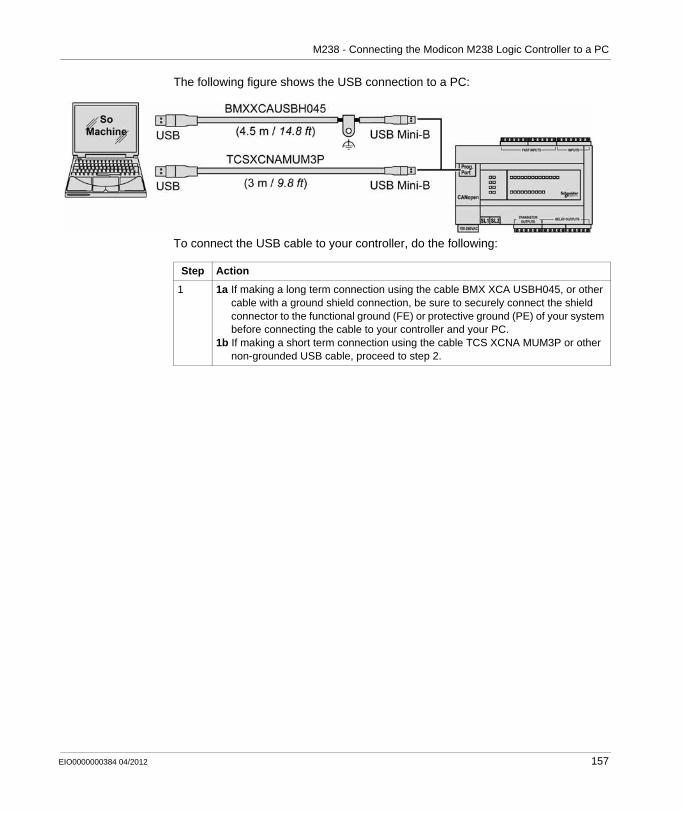
M238 - Connecting the Modicon M238 Logic Controller to a PC
The following figure shows the USB connection to a PC:
To connect the USB cable to your controller, do the following:
Step Action
1 1a If making a long term connection using the cable BMX XCA USBH045, or other cable with a ground shield connection, be sure to securely connect the shield connector to the functional ground (FE) or protective ground (PE) of your system before connecting the cable to your controller and your PC.
1b If making a short term connection using the cable TCS XCNA MUM3P or other non-grounded USB cable, proceed to step 2.
EIO0000000384 04/2012 157
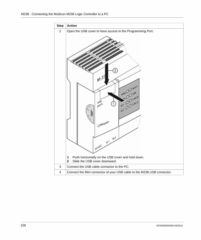
M238 - Connecting the Modicon M238 Logic Controller to a PC
2 Open the USB cover to have access to the Programming Port:
1 Push horizontally on the USB cover and hold down.2 Slide the USB cover downward.
3 Connect the USB cable connector to the PC.
4 Connect the Mini connector of your USB cable to the M238 USB connector.
Step Action
158 EIO0000000384 04/2012
M238 - Connecting the Modicon M238 Logic Controller to a PC
Active Path of the Controller
Introduction
After connecting the controller to the PC (see page 156), you must configure the Active Path of the controller in SoMachine.
NOTE: SoMachine cannot control multiple controllers simultaneously.
Active Path
To set the Active Path of the controller, proceed as follows:
Step Action
1 In the Configuration tab, double-click the controller.
2 Select the Communication Settings tab.
3 Click on the Add gateway button.
4 Click on the Scan network button.
5 Select the controller from the list of found devices by checking its Serial Number (the 6 last numbers on the controller) and clicking on the Set active path button.
6 Press ALT+F or click Cancel when the dialog box appears.
EIO0000000384 04/2012 159

M238 - Connecting the Modicon M238 Logic Controller to a PC
160 EIO0000000384 04/2012
EIO0000000384 04/2012
16
Modicon M238 Logic Controller
Loader Device Accessory
EIO0000000384 04/2012
Loader Device Accessory
Overview
This manual describes how to use the Loader Device Accessory
What’s in this Chapter?
This chapter contains the following sections:
Section Topic Page
16.1 About the Loader Device Accessory 162
16.2 Upload From SoMachine to the USB Memory Key 171
16.3 File Transfer with a USB Memory Key 172
16.4 Other Functionalities 177
161
Loader Device Accessory
16.1 About the Loader Device Accessory
What’s in this Section?
This section contains the following topics:
Topic Page
Loader Device AccessoryDescription 163
Physical Description 165
LED Status and Diagnostic 167
Firmware and SoMachine Software Compatibility 169
162 EIO0000000384 04/2012
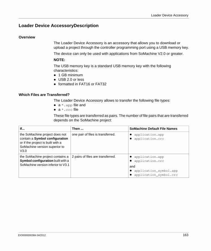
Loader Device Accessory
Loader Device AccessoryDescription
Overview
The Loader Device Accessory is an accessory that allows you to download or upload a project through the controller programming port using a USB memory key.
The device can only be used with applications from SoMachine V2.0 or greater.
NOTE:
The USB memory key is a standard USB memory key with the following characteristics:
1 GB minimumUSB 2.0 or lessformatted in FAT16 or FAT32
Which Files are Transferred?
The Loader Device Accessory allows to transfer the following file types:a *.app file anda *.crc file
These file types are transferred as pairs. The number of file pairs that are transferred depends on the SoMachine project:
If... Then ... SoMachine Default File Names
the SoMachine project does not contain a Symbol configuration or if the project is built with a SoMachine version superior to V3.0
one pair of files is transferred. application.appapplication.crc
the SoMachine project contains a Symbol configuration built with a SoMachine version inferior to V3.1
2 pairs of files are transferred. application.appapplication.crc
andapplication_symbol.appapplication_symbol.crc
EIO0000000384 04/2012 163
Loader Device Accessory
Functionalities
The Loader Device Accessory can be used in the following cases:Upload from SoMachine to the USB memory key (see page 171)Upload from the controller to the USB memory key (see page 173)Download from the USB memory key to the controller (see page 174)Set the controller to RUNNING state (see page 178)Update the firmware of the Loader Device Accessory (see page 179)
WARNINGUNINTENDED EQUIPMENT OPERATION
You must have operational knowledge of your machine or process before connecting this device to your controller.Be sure that your machine or process is in a know safe state (STOP, SHUTDOWN, INERT, etc.) before transitioning the Loader Device Accessory to the “On” switch position while connected to your controller.Be sure that guards are in place so that any potential unintended equipment operation will not cause injury to personnel or damage to equipment.You must have read and understood the user documentation of this and other devices involved in the functions performed by the Loader Device Accessory.
Failure to follow these instructions can result in death, serious injury, or equipment damage.
164 EIO0000000384 04/2012
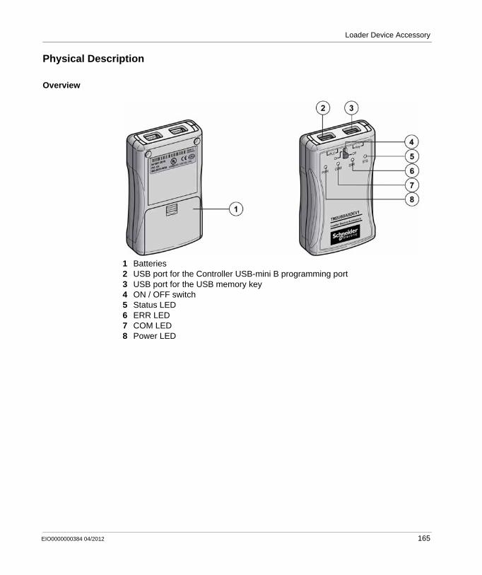
Loader Device Accessory
Physical Description
Overview
1 Batteries2 USB port for the Controller USB-mini B programming port3 USB port for the USB memory key4 ON / OFF switch5 Status LED6 ERR LED7 COM LED8 Power LED
EIO0000000384 04/2012 165
Loader Device Accessory
Battery
The Loader Device Accessory use 2 AA / LR6 alkaline batteries.
WARNINGINOPERABLE EQUIPMENT
Store the batteries in a cool, well ventilated area.Prolonged short circuit causes the battery to lose energy.Do not try to recharge the batteries provided with the device.Do not install the batteries backwards.Immediately discard batteries that show any sign of leakage or damage.Discard used batteries in accordance with local regulations.Do not mix with other battery types.
Failure to follow these instructions can result in death, serious injury, or equipment damage.
166 EIO0000000384 04/2012
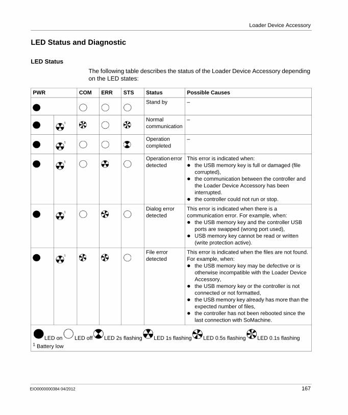
Loader Device Accessory
LED Status and Diagnostic
LED Status
The following table describes the status of the Loader Device Accessory depending on the LED states:
PWR COM ERR STS Status Possible Causes
Stand by –
Normal communication
–
Operation completed
–
Operation error detected
This error is indicated when:the USB memory key is full or damaged (file corrupted),the communication between the controller and the Loader Device Accessory has been interrupted.the controller could not run or stop.
Dialog error detected
This error is indicated when there is a communication error. For example, when:
the USB memory key and the controller USB ports are swapped (wrong port used),USB memory key cannot be read or written (write protection active).
File error detected
This error is indicated when the files are not found. For example, when:
the USB memory key may be defective or is otherwise incompatible with the Loader Device Accessory,the USB memory key or the controller is not connected or not formatted,the USB memory key already has more than the expected number of files,the controller has not been rebooted since the last connection with SoMachine.
LED on LED off LED 2s flashing LED 1s flashing LED 0.5s flashing LED 0.1s flashing1 Battery low
EIO0000000384 04/2012 167
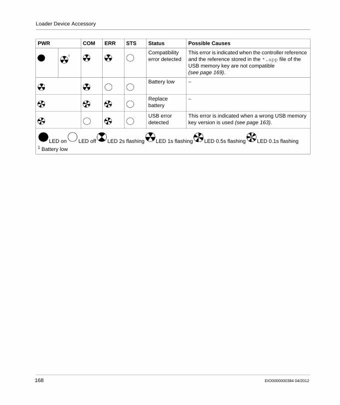
Loader Device Accessory
Compatibility error detected
This error is indicated when the controller reference and the reference stored in the *.app file of the USB memory key are not compatible (see page 169).
Battery low –
Replace battery
–
USB error detected
This error is indicated when a wrong USB memory key version is used (see page 163).
PWR COM ERR STS Status Possible Causes
LED on LED off LED 2s flashing LED 1s flashing LED 0.5s flashing LED 0.1s flashing1 Battery low
168 EIO0000000384 04/2012
Loader Device Accessory
Firmware and SoMachine Software Compatibility
Firmware Compatibility Rule
Logic controller firmware versions are made of 4 digits: X.Y.Z.T.
NOTE: The controller version of your application can be found with SoMachine. See the programming guide of your particular controller.
To successfully transfer an application to a controller, the firmware must be compatible.
A compatible firmware must follow these rules:The controller reference must be the sameX.Y digits must be identicalThe Z digit from the controller must be greater or equal to the Z digit from the application.T digit is irrelevant.
SoMachine Software Compatibility
The device can only be used with applications from SoMachine V2.0 or greater.
In order to have compatibility with versions of SoMachine prior to version 3.1, it is necessary to perform additional steps while creating the necessary files for download to a controller with a USB memory key.
When using SoMachine version 3.0 or earlier, or a project created with, or a context of, a version 3.0 or earlier, follow the steps below:
You must execute the Clean All, Build All sequence (steps 3 and 4 in the table above) in order that your Retain Data are properly initialized in your project.
Step Action
1 Open or create the project you want to transfer with the USB memory key using SoMachine.
2 Connect your USB memory key to your computer.NOTE: The USB memory key must be empty.
3 Select in the menu Build → Clean All.
4 Select in the menu Build → Build All.
5 Select in the menu Online → Create Boot Application.NOTE: SoMachine must be running in offline mode to be able to execute this command.
6 Define your project name and save it in the root of the USB memory key.NOTE: Save the files in the root of the USB memory key. Otherwise they will not be detected by the Loader Device Accessory.
EIO0000000384 04/2012 169

Loader Device Accessory
WARNINGUNINTENDED MACHINE OPERATION
Be sure to execute the Clean All, Build All sequence described above if using a version of SoMachine inferior to version 3.1, or a project originally created with, or in a context of, a version inferior to version 3.1.
Failure to follow these instructions can result in death, serious injury, or equipment damage.
170 EIO0000000384 04/2012
Loader Device Accessory
16.2 Upload From SoMachine to the USB Memory Key
Transfer From SoMachine to the USB Memory Key
Procedure
The following procedure describes how you can create the necessary files for download to a controller with a USB memory key.
NOTE: Only save one project on the USB memory key.
NOTE: If your project was created with a version of SoMachine inferior to version 3.1, or created in a context of a version less than 3.1, refer to the SoMachine software compatibility (see page 169) for important information.
Step Action
1 Open or create the project you want to transfer with the USB memory key using SoMachine.
2 Connect your USB memory key to your computer.NOTE: The USB memory key must be empty.
3 Select in the menu Online → Create Boot Application.NOTE: SoMachine must be running in offline mode to be able to execute this command.
4 Define your project name and save it in the root of the USB memory key.NOTE: Save the files in the root of the USB memory key. Otherwise they will not be detected by the Loader Device Accessory.
EIO0000000384 04/2012 171
Loader Device Accessory
16.3 File Transfer with a USB Memory Key
What’s in this Section?
This section contains the following topics:
Topic Page
Upload From the Controller to the USB Memory Key 173
Download From the USB Memory Key to the Controller 174
172 EIO0000000384 04/2012
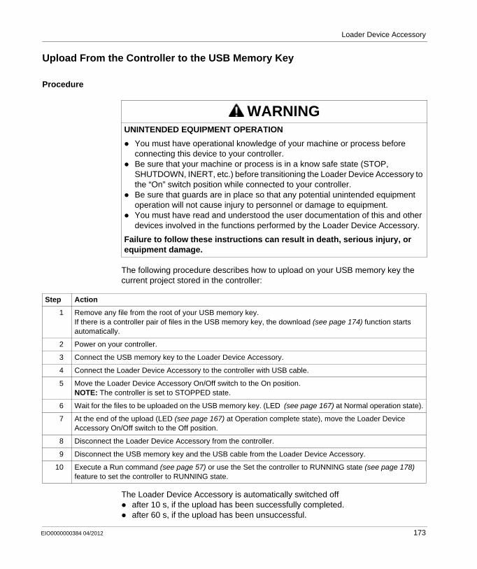
Loader Device Accessory
Upload From the Controller to the USB Memory Key
Procedure
The following procedure describes how to upload on your USB memory key the current project stored in the controller:
The Loader Device Accessory is automatically switched offafter 10 s, if the upload has been successfully completed.after 60 s, if the upload has been unsuccessful.
WARNINGUNINTENDED EQUIPMENT OPERATION
You must have operational knowledge of your machine or process before connecting this device to your controller.Be sure that your machine or process is in a know safe state (STOP, SHUTDOWN, INERT, etc.) before transitioning the Loader Device Accessory to the “On” switch position while connected to your controller.Be sure that guards are in place so that any potential unintended equipment operation will not cause injury to personnel or damage to equipment.You must have read and understood the user documentation of this and other devices involved in the functions performed by the Loader Device Accessory.
Failure to follow these instructions can result in death, serious injury, or equipment damage.
Step Action
1 Remove any file from the root of your USB memory key.If there is a controller pair of files in the USB memory key, the download (see page 174) function starts automatically.
2 Power on your controller.
3 Connect the USB memory key to the Loader Device Accessory.
4 Connect the Loader Device Accessory to the controller with USB cable.
5 Move the Loader Device Accessory On/Off switch to the On position.NOTE: The controller is set to STOPPED state.
6 Wait for the files to be uploaded on the USB memory key. (LED (see page 167) at Normal operation state).
7 At the end of the upload (LED (see page 167) at Operation complete state), move the Loader Device Accessory On/Off switch to the Off position.
8 Disconnect the Loader Device Accessory from the controller.
9 Disconnect the USB memory key and the USB cable from the Loader Device Accessory.
10 Execute a Run command (see page 57) or use the Set the controller to RUNNING state (see page 178) feature to set the controller to RUNNING state.
EIO0000000384 04/2012 173
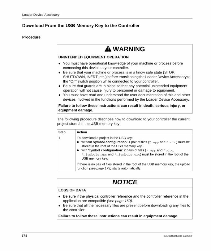
Loader Device Accessory
Download From the USB Memory Key to the Controller
Procedure
The following procedure describes how to download to your controller the current project stored in the USB memory key:
WARNINGUNINTENDED EQUIPMENT OPERATION
You must have operational knowledge of your machine or process before connecting this device to your controller.Be sure that your machine or process is in a know safe state (STOP, SHUTDOWN, INERT, etc.) before transitioning the Loader Device Accessory to the “On” switch position while connected to your controller.Be sure that guards are in place so that any potential unintended equipment operation will not cause injury to personnel or damage to equipment.You must have read and understood the user documentation of this and other devices involved in the functions performed by the Loader Device Accessory.
Failure to follow these instructions can result in death, serious injury, or equipment damage.
Step Action
1 To download a project in the USB key:without Symbol configuration: 1 pair of files (*.app and *.crc) must be stored in the root of the USB memory key.with Symbol configuration: 2 pairs of files (*.app and *.crc, *_Symbols.app and *_Symbols.crc) must be stored in the root of the USB memory key.
If there is no pair of files stored in the root of the USB memory key, the upload function (see page 173) starts automatically.
NOTICELOSS OF DATA
Be sure if the physical controller reference and the controller reference in the application are compatible (see page 169).Be sure that all the necessary files are present before downloading any files to the controller.
Failure to follow these instructions can result in equipment damage.
174 EIO0000000384 04/2012
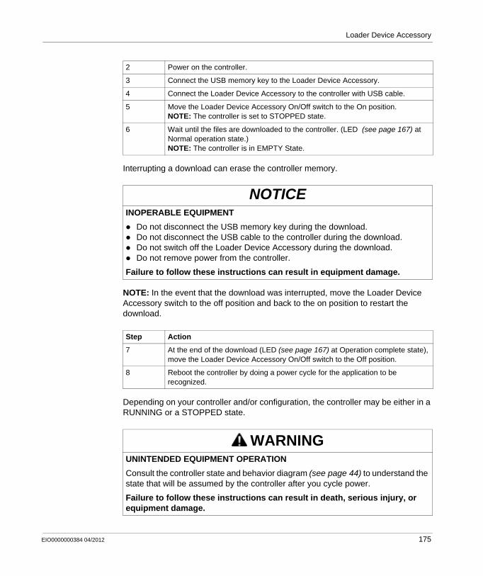
Loader Device Accessory
Interrupting a download can erase the controller memory.
NOTE: In the event that the download was interrupted, move the Loader Device Accessory switch to the off position and back to the on position to restart the download.
Depending on your controller and/or configuration, the controller may be either in a RUNNING or a STOPPED state.
2 Power on the controller.
3 Connect the USB memory key to the Loader Device Accessory.
4 Connect the Loader Device Accessory to the controller with USB cable.
5 Move the Loader Device Accessory On/Off switch to the On position.NOTE: The controller is set to STOPPED state.
6 Wait until the files are downloaded to the controller. (LED (see page 167) at Normal operation state.)NOTE: The controller is in EMPTY State.
NOTICEINOPERABLE EQUIPMENT
Do not disconnect the USB memory key during the download.Do not disconnect the USB cable to the controller during the download.Do not switch off the Loader Device Accessory during the download.Do not remove power from the controller.
Failure to follow these instructions can result in equipment damage.
Step Action
7 At the end of the download (LED (see page 167) at Operation complete state), move the Loader Device Accessory On/Off switch to the Off position.
8 Reboot the controller by doing a power cycle for the application to be recognized.
WARNINGUNINTENDED EQUIPMENT OPERATION
Consult the controller state and behavior diagram (see page 44) to understand the state that will be assumed by the controller after you cycle power.
Failure to follow these instructions can result in death, serious injury, or equipment damage.
EIO0000000384 04/2012 175
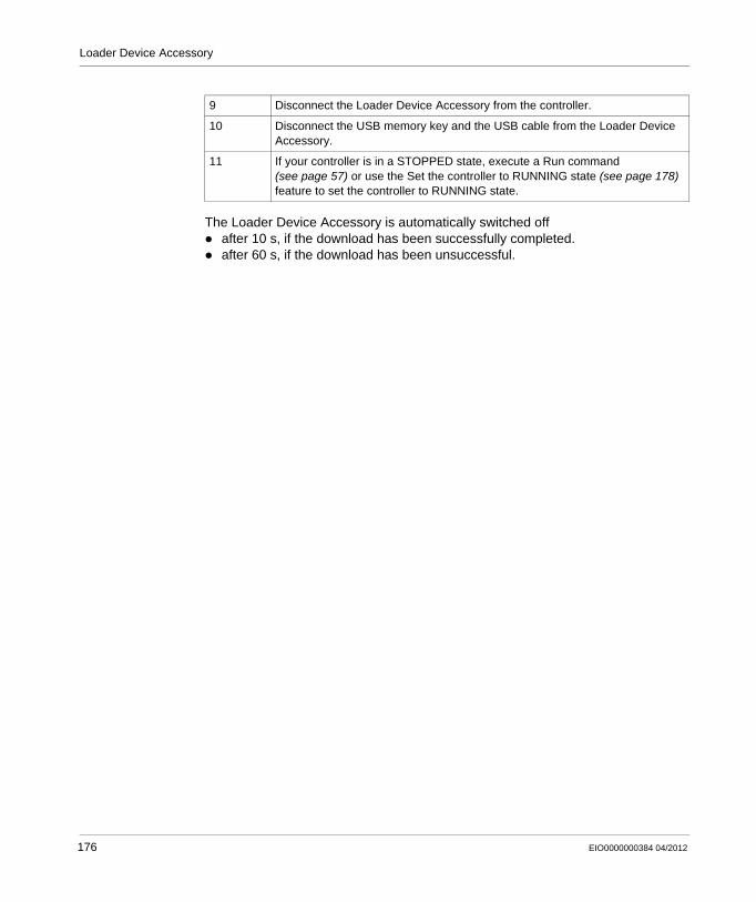
Loader Device Accessory
The Loader Device Accessory is automatically switched offafter 10 s, if the download has been successfully completed.after 60 s, if the download has been unsuccessful.
9 Disconnect the Loader Device Accessory from the controller.
10 Disconnect the USB memory key and the USB cable from the Loader Device Accessory.
11 If your controller is in a STOPPED state, execute a Run command (see page 57) or use the Set the controller to RUNNING state (see page 178) feature to set the controller to RUNNING state.
176 EIO0000000384 04/2012
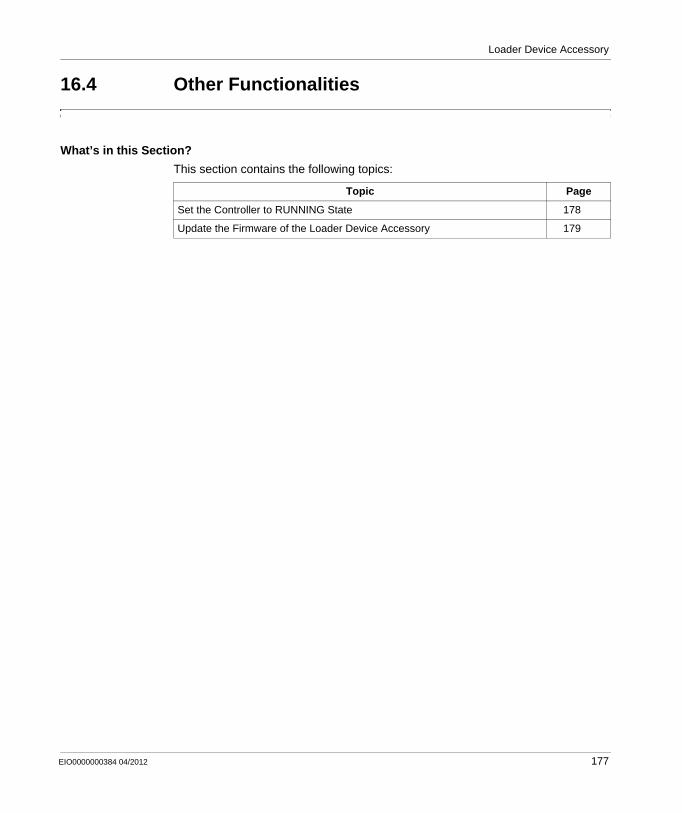
Loader Device Accessory
16.4 Other Functionalities
What’s in this Section?
This section contains the following topics:
Topic Page
Set the Controller to RUNNING State 178
Update the Firmware of the Loader Device Accessory 179
EIO0000000384 04/2012 177
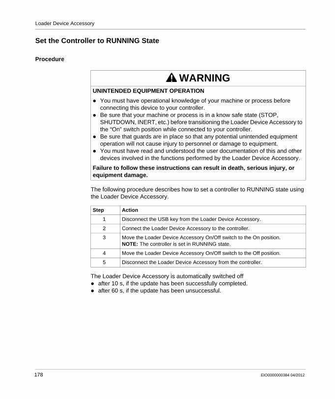
Loader Device Accessory
Set the Controller to RUNNING State
Procedure
The following procedure describes how to set a controller to RUNNING state using the Loader Device Accessory.
The Loader Device Accessory is automatically switched offafter 10 s, if the update has been successfully completed.after 60 s, if the update has been unsuccessful.
WARNINGUNINTENDED EQUIPMENT OPERATION
You must have operational knowledge of your machine or process before connecting this device to your controller.Be sure that your machine or process is in a know safe state (STOP, SHUTDOWN, INERT, etc.) before transitioning the Loader Device Accessory to the “On” switch position while connected to your controller.Be sure that guards are in place so that any potential unintended equipment operation will not cause injury to personnel or damage to equipment.You must have read and understood the user documentation of this and other devices involved in the functions performed by the Loader Device Accessory.
Failure to follow these instructions can result in death, serious injury, or equipment damage.
Step Action
1 Disconnect the USB key from the Loader Device Accessory.
2 Connect the Loader Device Accessory to the controller.
3 Move the Loader Device Accessory On/Off switch to the On position.NOTE: The controller is set in RUNNING state.
4 Move the Loader Device Accessory On/Off switch to the Off position.
5 Disconnect the Loader Device Accessory from the controller.
178 EIO0000000384 04/2012
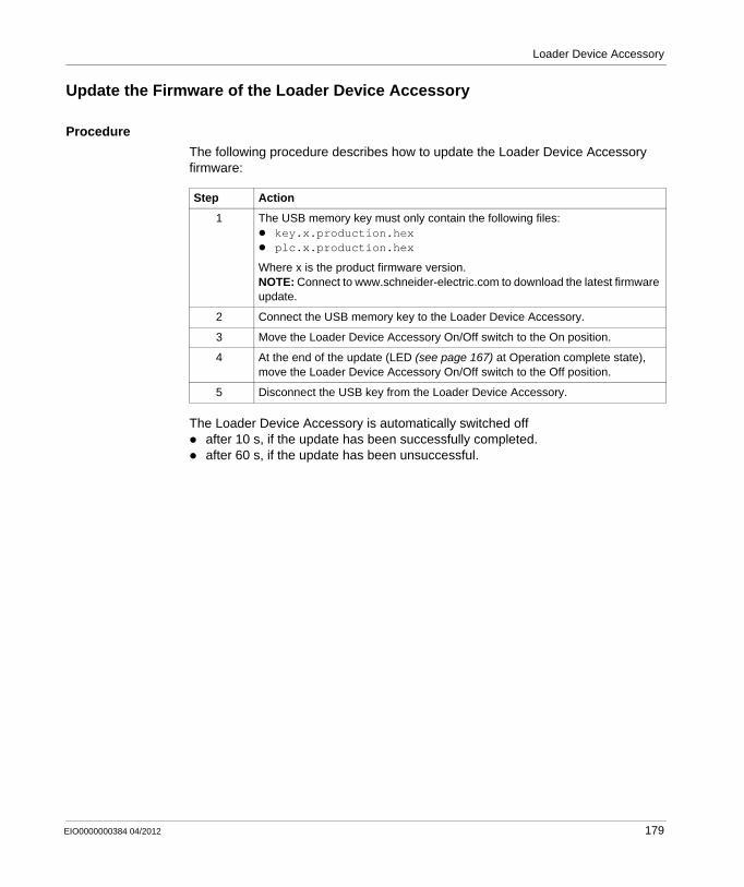
Loader Device Accessory
Update the Firmware of the Loader Device Accessory
Procedure
The following procedure describes how to update the Loader Device Accessory firmware:
The Loader Device Accessory is automatically switched offafter 10 s, if the update has been successfully completed.after 60 s, if the update has been unsuccessful.
Step Action
1 The USB memory key must only contain the following files:key.x.production.hexplc.x.production.hex
Where x is the product firmware version.NOTE: Connect to www.schneider-electric.com to download the latest firmware update.
2 Connect the USB memory key to the Loader Device Accessory.
3 Move the Loader Device Accessory On/Off switch to the On position.
4 At the end of the update (LED (see page 167) at Operation complete state), move the Loader Device Accessory On/Off switch to the Off position.
5 Disconnect the USB key from the Loader Device Accessory.
EIO0000000384 04/2012 179

Loader Device Accessory
180 EIO0000000384 04/2012
EIO0000000384 04/2012
17
Modicon M238 Logic Controller
Updating the Controller Firmware
EIO0000000384 04/2012
Updating the Controller Firmware
Overview
This chapter provides detailed instructions on using the Windows Exec Loader to update the firmware of your M238 controller.
What’s in this Chapter?
This chapter contains the following topics:
Topic Page
Updating Through Serial Line 182
Updating Through USB 185
Launching the Exec Loader Wizard 187
Step 1 - Welcome 188
Step 2 - Settings 189
Step 3 - File and Device Exec Properties 191
Step 4 - Transfer Progress 193
181
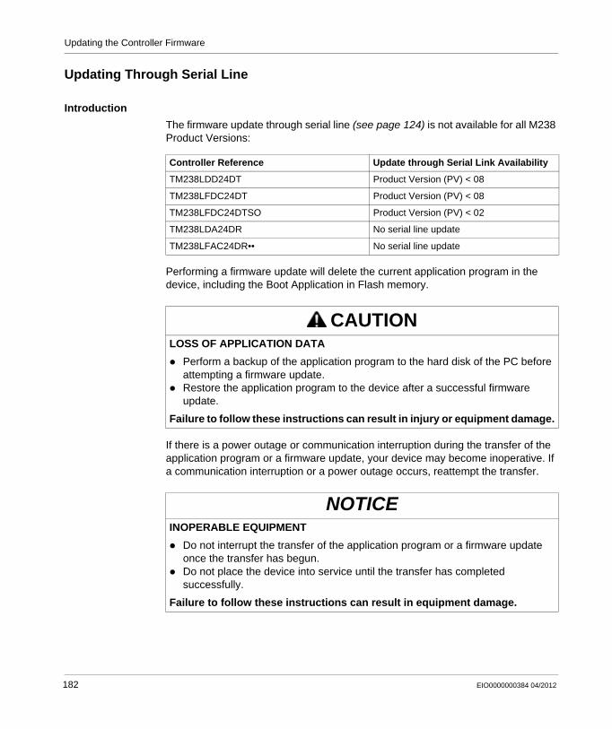
Updating the Controller Firmware
Updating Through Serial Line
Introduction
The firmware update through serial line (see page 124) is not available for all M238 Product Versions:
Performing a firmware update will delete the current application program in the device, including the Boot Application in Flash memory.
If there is a power outage or communication interruption during the transfer of the application program or a firmware update, your device may become inoperative. If a communication interruption or a power outage occurs, reattempt the transfer.
Controller Reference Update through Serial Link Availability
TM238LDD24DT Product Version (PV) < 08
TM238LFDC24DT Product Version (PV) < 08
TM238LFDC24DTSO Product Version (PV) < 02
TM238LDA24DR No serial line update
TM238LFAC24DR•• No serial line update
CAUTIONLOSS OF APPLICATION DATA
Perform a backup of the application program to the hard disk of the PC before attempting a firmware update.Restore the application program to the device after a successful firmware update.
Failure to follow these instructions can result in injury or equipment damage.
NOTICEINOPERABLE EQUIPMENT
Do not interrupt the transfer of the application program or a firmware update once the transfer has begun.Do not place the device into service until the transfer has completed successfully.
Failure to follow these instructions can result in equipment damage.
182 EIO0000000384 04/2012
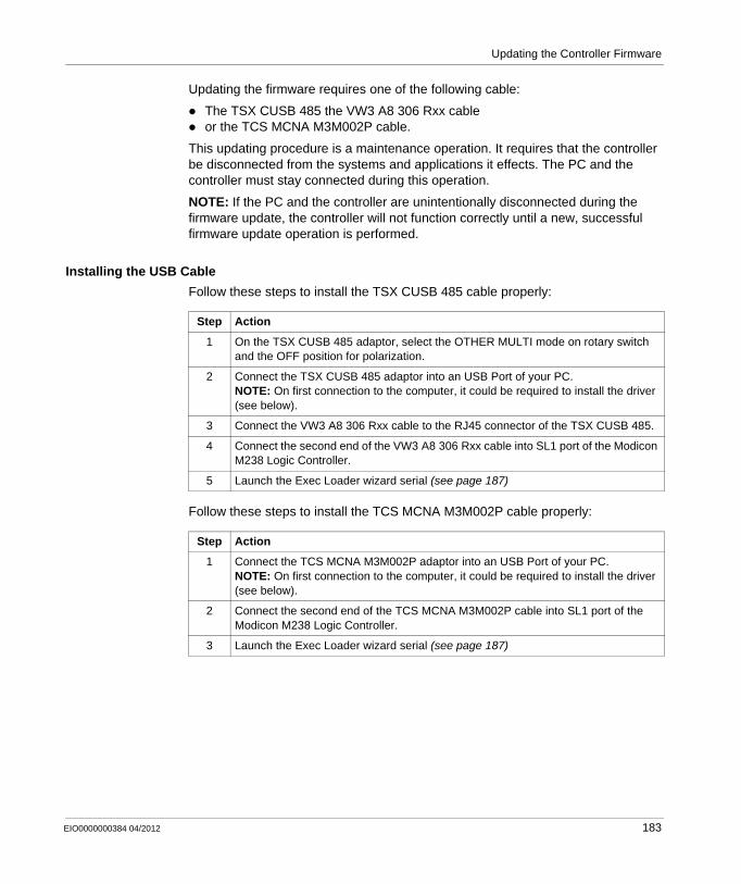
Updating the Controller Firmware
Updating the firmware requires one of the following cable:
The TSX CUSB 485 the VW3 A8 306 Rxx cableor the TCS MCNA M3M002P cable.
This updating procedure is a maintenance operation. It requires that the controller be disconnected from the systems and applications it effects. The PC and the controller must stay connected during this operation.
NOTE: If the PC and the controller are unintentionally disconnected during the firmware update, the controller will not function correctly until a new, successful firmware update operation is performed.
Installing the USB Cable
Follow these steps to install the TSX CUSB 485 cable properly:
Follow these steps to install the TCS MCNA M3M002P cable properly:
Step Action
1 On the TSX CUSB 485 adaptor, select the OTHER MULTI mode on rotary switch and the OFF position for polarization.
2 Connect the TSX CUSB 485 adaptor into an USB Port of your PC.NOTE: On first connection to the computer, it could be required to install the driver (see below).
3 Connect the VW3 A8 306 Rxx cable to the RJ45 connector of the TSX CUSB 485.
4 Connect the second end of the VW3 A8 306 Rxx cable into SL1 port of the Modicon M238 Logic Controller.
5 Launch the Exec Loader wizard serial (see page 187)
Step Action
1 Connect the TCS MCNA M3M002P adaptor into an USB Port of your PC.NOTE: On first connection to the computer, it could be required to install the driver (see below).
2 Connect the second end of the TCS MCNA M3M002P cable into SL1 port of the Modicon M238 Logic Controller.
3 Launch the Exec Loader wizard serial (see page 187)
EIO0000000384 04/2012 183
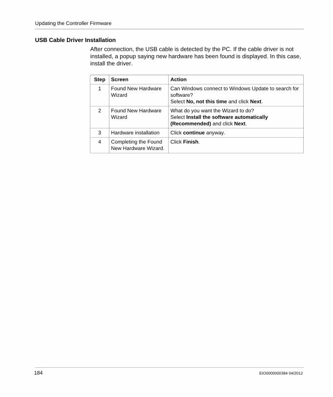
Updating the Controller Firmware
USB Cable Driver Installation
After connection, the USB cable is detected by the PC. If the cable driver is not installed, a popup saying new hardware has been found is displayed. In this case, install the driver.
Step Screen Action
1 Found New Hardware Wizard
Can Windows connect to Windows Update to search for software?Select No, not this time and click Next.
2 Found New Hardware Wizard
What do you want the Wizard to do?Select Install the software automatically (Recommended) and click Next.
3 Hardware installation Click continue anyway.
4 Completing the Found New Hardware Wizard.
Click Finish.
184 EIO0000000384 04/2012
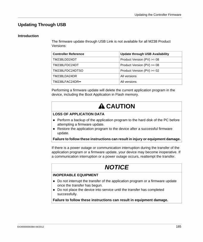
Updating the Controller Firmware
Updating Through USB
Introduction
The firmware update through USB Link is not available for all M238 Product Versions:
Performing a firmware update will delete the current application program in the device, including the Boot Application in Flash memory.
If there is a power outage or communication interruption during the transfer of the application program or a firmware update, your device may become inoperative. If a communication interruption or a power outage occurs, reattempt the transfer.
Controller Reference Update through USB Availability
TM238LDD24DT Product Version (PV) >= 08
TM238LFDC24DT Product Version (PV) >= 08
TM238LFDC24DTSO Product Version (PV) >= 02
TM238LDA24DR All versions
TM238LFAC24DR•• All versions
CAUTIONLOSS OF APPLICATION DATA
Perform a backup of the application program to the hard disk of the PC before attempting a firmware update.Restore the application program to the device after a successful firmware update.
Failure to follow these instructions can result in injury or equipment damage.
NOTICEINOPERABLE EQUIPMENT
Do not interrupt the transfer of the application program or a firmware update once the transfer has begun.Do not place the device into service until the transfer has completed successfully.
Failure to follow these instructions can result in equipment damage.
EIO0000000384 04/2012 185
Updating the Controller Firmware
The Serial Line port(s) of your controller are configured for the SoMachine protocol by default when new or when you update the controller firmware. The SoMachine protocol is incompatible with that of other protocols such as Modbus Serial Line. Connecting a new controller to, or updating the firmware of a controller connected to, an active Modbus configured serial line can cause the other devices on the serial line to stop communicating. Make sure that the controller is not connected to an active Modbus serial line network before first downloading a valid application that has the concerned port or ports properly configured for the intended protocol.
Before starting the firmware update procedure, ensure you have:
USB cable TCS XCNA MUM3PModicon M238 Logic Controller
This updating procedure is a maintenance operation. It requires that the controller be disconnected from the systems and applications it effects. The PC and the controller must stay connected during this operation.
NOTE: If the PC and the controller are unintentionally disconnected during a firmware update, the controller will not function correctly until a new, successful firmware update operation is performed.
Installing Cables
Follow these steps to install the cables properly:
NOTICEUNINTENDED EQUIPMENT OPERATION
Be sure your application has the Serial Line port(s) properly configured for Modbus before physically connecting the controller to an operational Modbus Serial Line network.
Failure to follow these instructions can result in equipment damage.
Step Action
1 Plug the TCS XCNA MUM3P cable to an USB Port of your PC. (see page 156)
2 Plug the second end of the cable to the USB port of the controller.
3 Launch the Exec Loader Wizard USB (see page 187)
186 EIO0000000384 04/2012
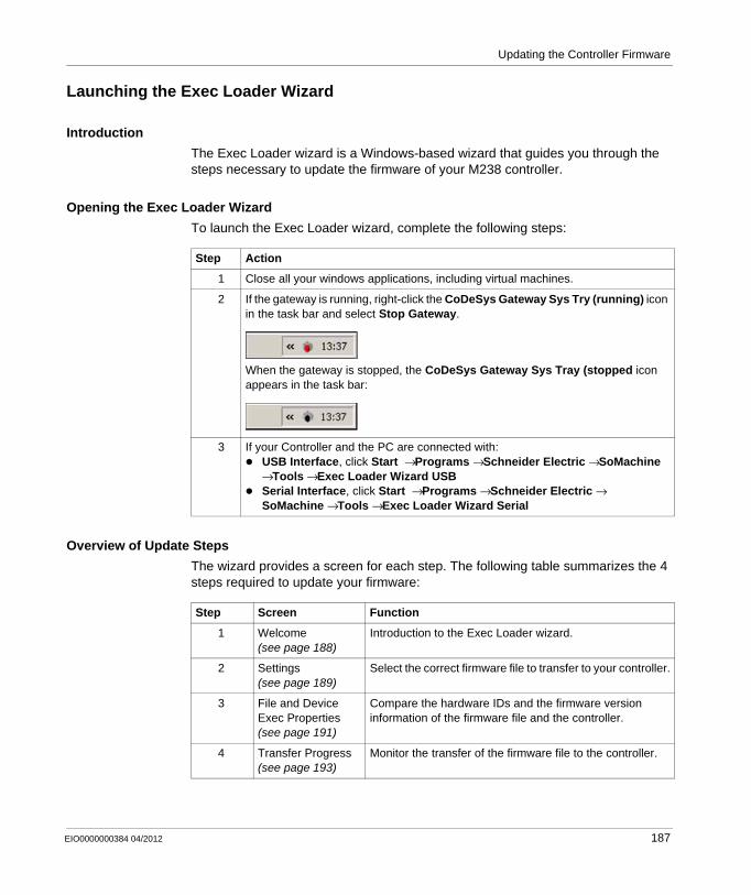
Updating the Controller Firmware
Launching the Exec Loader Wizard
Introduction
The Exec Loader wizard is a Windows-based wizard that guides you through the steps necessary to update the firmware of your M238 controller.
Opening the Exec Loader Wizard
To launch the Exec Loader wizard, complete the following steps:
Overview of Update Steps
The wizard provides a screen for each step. The following table summarizes the 4 steps required to update your firmware:
Step Action
1 Close all your windows applications, including virtual machines.
2 If the gateway is running, right-click the CoDeSys Gateway Sys Try (running) icon in the task bar and select Stop Gateway.
When the gateway is stopped, the CoDeSys Gateway Sys Tray (stopped icon appears in the task bar:
3 If your Controller and the PC are connected with:USB Interface, click Start → Programs → Schneider Electric → SoMachine → Tools → Exec Loader Wizard USBSerial Interface, click Start → Programs → Schneider Electric → SoMachine → Tools → Exec Loader Wizard Serial
Step Screen Function
1 Welcome (see page 188)
Introduction to the Exec Loader wizard.
2 Settings (see page 189)
Select the correct firmware file to transfer to your controller.
3 File and Device Exec Properties (see page 191)
Compare the hardware IDs and the firmware version information of the firmware file and the controller.
4 Transfer Progress (see page 193)
Monitor the transfer of the firmware file to the controller.
EIO0000000384 04/2012 187
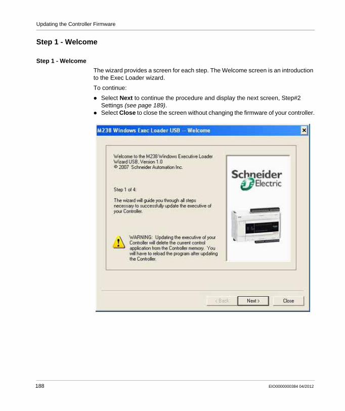
Updating the Controller Firmware
Step 1 - Welcome
Step 1 - Welcome
The wizard provides a screen for each step. The Welcome screen is an introduction to the Exec Loader wizard.
To continue:
Select Next to continue the procedure and display the next screen, Step#2 Settings (see page 189). Select Close to close the screen without changing the firmware of your controller.
188 EIO0000000384 04/2012
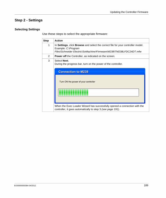
Updating the Controller Firmware
Step 2 - Settings
Selecting Settings
Use these steps to select the appropriate firmware:
Step Action
1 In Settings, click Browse and select the correct file for your controller model. Example: C:\Program Files\Schneider Electric\SoMachine\Firmware\M238\TM238LFDC24DT.mfw
2 Power off the Controller, as indicated on the screen.
3 Select Next.During the progress bar, turn on the power of the controller.
When the Exec Loader Wizard has successfully opened a connection with the controller, it goes automatically to step 3 (see page 191).
EIO0000000384 04/2012 189
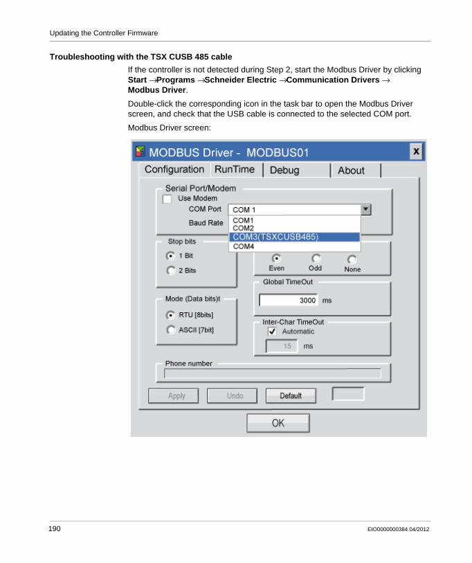
Updating the Controller Firmware
Troubleshooting with the TSX CUSB 485 cable
If the controller is not detected during Step 2, start the Modbus Driver by clicking Start → Programs → Schneider Electric → Communication Drivers → Modbus Driver.
Double-click the corresponding icon in the task bar to open the Modbus Driver screen, and check that the USB cable is connected to the selected COM port.
Modbus Driver screen:
190 EIO0000000384 04/2012
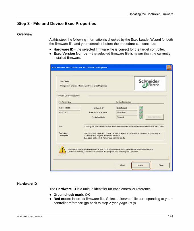
Updating the Controller Firmware
Step 3 - File and Device Exec Properties
Overview
At this step, the following information is checked by the Exec Loader Wizard for both the firmware file and your controller before the procedure can continue:
Hardware ID - the selected firmware file is correct for the target controller.Exec Version Number - the selected firmware file is newer than the currently installed firmware.
Hardware ID
The Hardware ID is a unique identifier for each controller reference:
Green check mark: OKRed cross: incorrect firmware file. Select a firmware file corresponding to your controller reference (go back to step 2 (see page 189))
EIO0000000384 04/2012 191

Updating the Controller Firmware
Exec Version Number
The Exec Version Number identifies the version of the firmware:
Green check mark: you will update your controller to a newer version of the firmwareYellow check mark: you will downgrade your controller to an older version of the firmware or update your controller with the same version of the current firmware
Starting the Transfer
Click on the Next button to start the transfer.
192 EIO0000000384 04/2012
Updating the Controller Firmware
Step 4 - Transfer Progress
Overview
In this screen you can monitor the transfer progress.
The remaining time information is available after a while.
If Transfer is Successful
If the transfer is successful, a message box is displayed to allow for another transfer. Two options are available:
Yes - the wizard returns to Step 2 - Settings (see page 189) and you can set up another transfer.No - click on the Close button to exit the wizard. This completes the update procedure.
If Transfer is not Successful
If the transfer is interrupted (for example, due to a loss of communication), a message box is displayed allowing a retry of the transfer. Two options are available:
Yes - the wizard returns to Step 3 - Files and Device Exec Properties (see page 191) and you can try another transfer.No - click on the Close button to exit the wizard.
Your controller remains inoperative until a successful transfer has been accomplished.
NOTICEINOPERABLE EQUIPMENT
Do not interrupt the transfer of the application program or a firmware update once the transfer has begun.Do not place the device into service until the transfer has completed successfully.
Failure to follow these instructions can result in equipment damage.
EIO0000000384 04/2012 193

Updating the Controller Firmware
194 EIO0000000384 04/2012
EIO0000000384 04/2012
18
Modicon M238 Logic Controller
Modicon M238 Logic Controller - Troubleshooting and FAQ
EIO0000000384 04/2012
Modicon M238 Logic Controller - Troubleshooting and FAQ
What’s in this Chapter?
This chapter contains the following topics:
Topic Page
Troubleshooting 196
Frequently Asked Questions 203
195
Modicon M238 Logic Controller - Troubleshooting and FAQ
Troubleshooting
Introduction
This section describes the procedures to troubleshoot your Modicon M238 Logic Controller.
Transferring the Application is not Possible
Possible causes:PC cannot communicate with the controller.Is your application valid?Is the CoDeSys gateway running?
Resolution:Refer to the part below (Communication Between SoMachine and the Modicon M238 Logic Controller (see page 196)).Your application program must be valid. Refer to the debugging part of the CoDeSys onlin help.The CoDeSys gateway must be running:a. click the CoDeSys Gateway SysTray (stopped) icon in the task bar,b. select Start Gateway.
Communication Between SoMachine on a Computer and the Modicon M238 Logic Controller is not Possible.
Possible causes:Incorrect cable usage.PLC not detected by the PC.Communication settings are not correct.The controller is not operating correctly.
196 EIO0000000384 04/2012
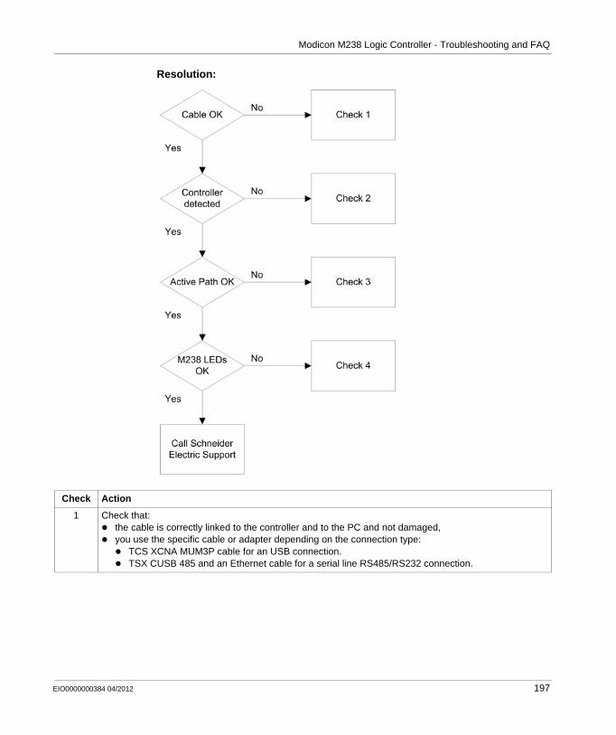
Modicon M238 Logic Controller - Troubleshooting and FAQ
Resolution:
Check Action
1 Check that:the cable is correctly linked to the controller and to the PC and not damaged,you use the specific cable or adapter depending on the connection type:
TCS XCNA MUM3P cable for an USB connection.TSX CUSB 485 and an Ethernet cable for a serial line RS485/RS232 connection.
EIO0000000384 04/2012 197
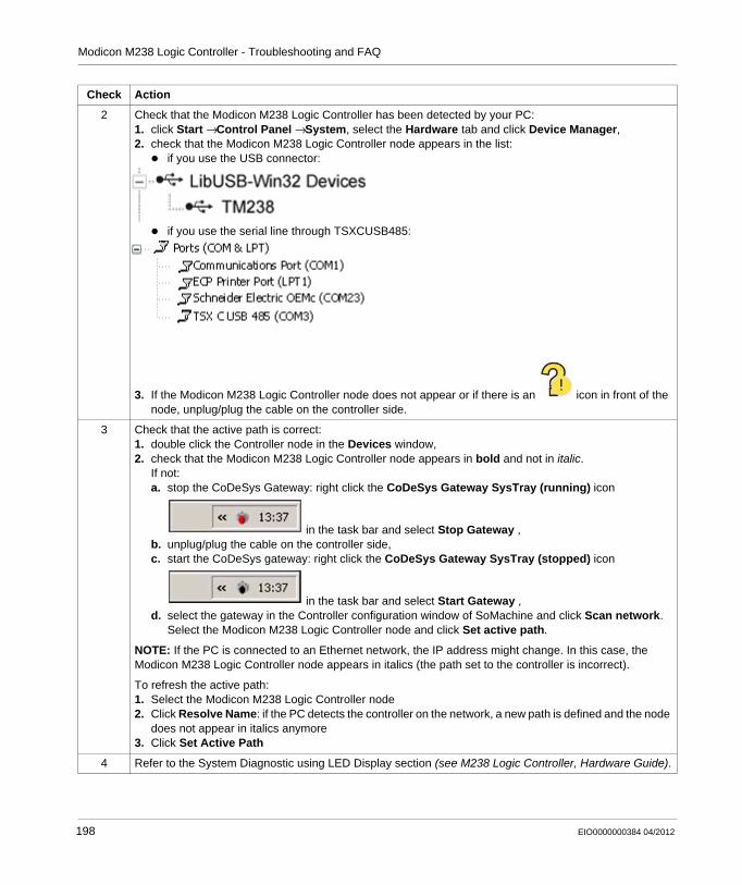
Modicon M238 Logic Controller - Troubleshooting and FAQ
2 Check that the Modicon M238 Logic Controller has been detected by your PC:1. click Start → Control Panel → System, select the Hardware tab and click Device Manager,2. check that the Modicon M238 Logic Controller node appears in the list:
if you use the USB connector:
if you use the serial line through TSXCUSB485:
3. If the Modicon M238 Logic Controller node does not appear or if there is an icon in front of the node, unplug/plug the cable on the controller side.
3 Check that the active path is correct:1. double click the Controller node in the Devices window, 2. check that the Modicon M238 Logic Controller node appears in bold and not in italic.
If not:a. stop the CoDeSys Gateway: right click the CoDeSys Gateway SysTray (running) icon
in the task bar and select Stop Gateway ,b. unplug/plug the cable on the controller side,c. start the CoDeSys gateway: right click the CoDeSys Gateway SysTray (stopped) icon
in the task bar and select Start Gateway ,d. select the gateway in the Controller configuration window of SoMachine and click Scan network.
Select the Modicon M238 Logic Controller node and click Set active path.
NOTE: If the PC is connected to an Ethernet network, the IP address might change. In this case, the Modicon M238 Logic Controller node appears in italics (the path set to the controller is incorrect).
To refresh the active path:1. Select the Modicon M238 Logic Controller node2. Click Resolve Name: if the PC detects the controller on the network, a new path is defined and the node
does not appear in italics anymore3. Click Set Active Path
4 Refer to the System Diagnostic using LED Display section (see M238 Logic Controller, Hardware Guide).
Check Action
198 EIO0000000384 04/2012
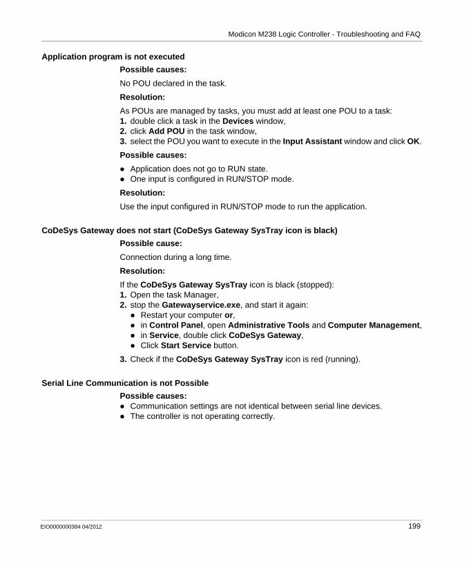
Modicon M238 Logic Controller - Troubleshooting and FAQ
Application program is not executed
Possible causes:
No POU declared in the task.
Resolution:
As POUs are managed by tasks, you must add at least one POU to a task:1. double click a task in the Devices window,2. click Add POU in the task window,3. select the POU you want to execute in the Input Assistant window and click OK.
Possible causes:
Application does not go to RUN state.One input is configured in RUN/STOP mode.
Resolution:
Use the input configured in RUN/STOP mode to run the application.
CoDeSys Gateway does not start (CoDeSys Gateway SysTray icon is black)
Possible cause:
Connection during a long time.
Resolution:
If the CoDeSys Gateway SysTray icon is black (stopped):1. Open the task Manager,2. stop the Gatewayservice.exe, and start it again:
Restart your computer or,in Control Panel, open Administrative Tools and Computer Management,in Service, double click CoDeSys Gateway,Click Start Service button.
3. Check if the CoDeSys Gateway SysTray icon is red (running).
Serial Line Communication is not Possible
Possible causes:Communication settings are not identical between serial line devices.The controller is not operating correctly.
EIO0000000384 04/2012 199
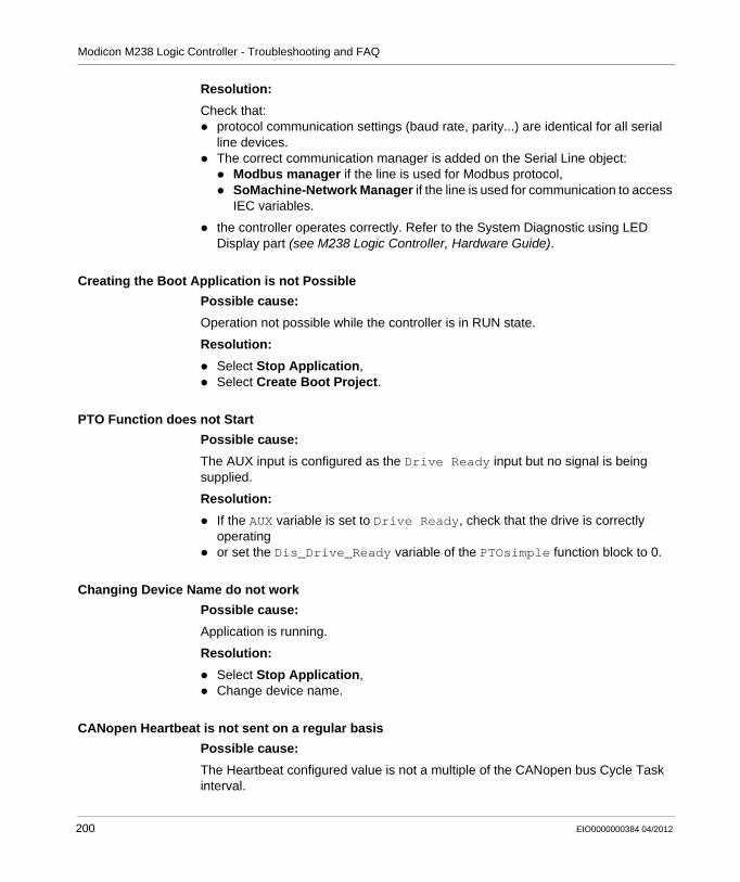
Modicon M238 Logic Controller - Troubleshooting and FAQ
Resolution:
Check that:protocol communication settings (baud rate, parity...) are identical for all serial line devices.The correct communication manager is added on the Serial Line object:
Modbus manager if the line is used for Modbus protocol, SoMachine-Network Manager if the line is used for communication to access IEC variables.
the controller operates correctly. Refer to the System Diagnostic using LED Display part (see M238 Logic Controller, Hardware Guide).
Creating the Boot Application is not Possible
Possible cause:
Operation not possible while the controller is in RUN state.
Resolution:
Select Stop Application,Select Create Boot Project.
PTO Function does not Start
Possible cause:
The AUX input is configured as the Drive Ready input but no signal is being supplied.
Resolution:
If the AUX variable is set to Drive Ready, check that the drive is correctly operatingor set the Dis_Drive_Ready variable of the PTOsimple function block to 0.
Changing Device Name do not work
Possible cause:
Application is running.
Resolution:
Select Stop Application,Change device name.
CANopen Heartbeat is not sent on a regular basis
Possible cause:
The Heartbeat configured value is not a multiple of the CANopen bus Cycle Task interval.
200 EIO0000000384 04/2012
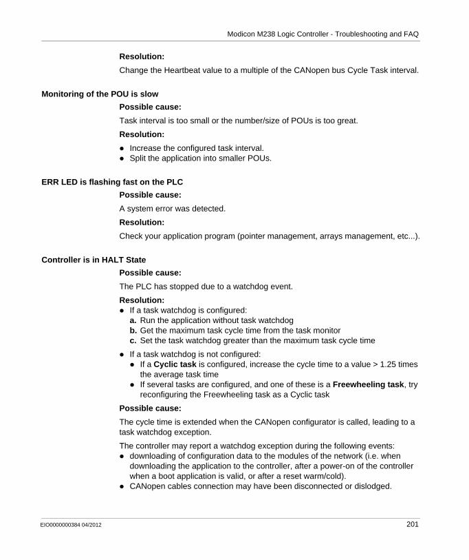
Modicon M238 Logic Controller - Troubleshooting and FAQ
Resolution:
Change the Heartbeat value to a multiple of the CANopen bus Cycle Task interval.
Monitoring of the POU is slow
Possible cause:
Task interval is too small or the number/size of POUs is too great.
Resolution:
Increase the configured task interval.Split the application into smaller POUs.
ERR LED is flashing fast on the PLC
Possible cause:
A system error was detected.
Resolution:
Check your application program (pointer management, arrays management, etc...).
Controller is in HALT State
Possible cause:
The PLC has stopped due to a watchdog event.
Resolution:If a task watchdog is configured:a. Run the application without task watchdogb. Get the maximum task cycle time from the task monitorc. Set the task watchdog greater than the maximum task cycle time
If a task watchdog is not configured:If a Cyclic task is configured, increase the cycle time to a value > 1.25 times the average task timeIf several tasks are configured, and one of these is a Freewheeling task, try reconfiguring the Freewheeling task as a Cyclic task
Possible cause:
The cycle time is extended when the CANopen configurator is called, leading to a task watchdog exception.
The controller may report a watchdog exception during the following events:downloading of configuration data to the modules of the network (i.e. when downloading the application to the controller, after a power-on of the controller when a boot application is valid, or after a reset warm/cold).CANopen cables connection may have been disconnected or dislodged.
EIO0000000384 04/2012 201
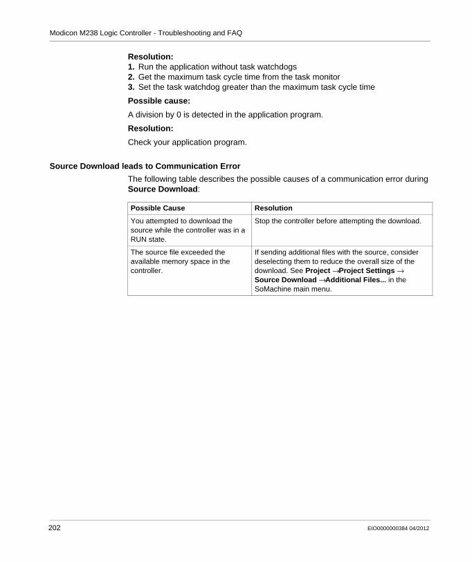
Modicon M238 Logic Controller - Troubleshooting and FAQ
Resolution:1. Run the application without task watchdogs2. Get the maximum task cycle time from the task monitor3. Set the task watchdog greater than the maximum task cycle time
Possible cause:
A division by 0 is detected in the application program.
Resolution:
Check your application program.
Source Download leads to Communication Error
The following table describes the possible causes of a communication error during Source Download:
Possible Cause Resolution
You attempted to download the source while the controller was in a RUN state.
Stop the controller before attempting the download.
The source file exceeded the available memory space in the controller.
If sending additional files with the source, consider deselecting them to reduce the overall size of the download. See Project → Project Settings → Source Download → Additional Files... in the SoMachine main menu.
202 EIO0000000384 04/2012
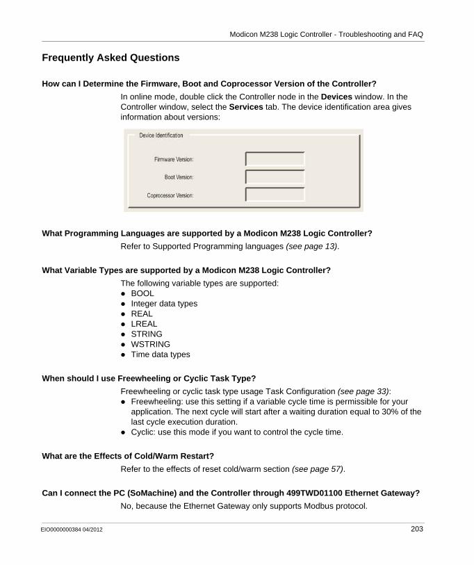
Modicon M238 Logic Controller - Troubleshooting and FAQ
Frequently Asked Questions
How can I Determine the Firmware, Boot and Coprocessor Version of the Controller?
In online mode, double click the Controller node in the Devices window. In the Controller window, select the Services tab. The device identification area gives information about versions:
What Programming Languages are supported by a Modicon M238 Logic Controller?
Refer to Supported Programming languages (see page 13).
What Variable Types are supported by a Modicon M238 Logic Controller?
The following variable types are supported:BOOLInteger data typesREALLREALSTRINGWSTRINGTime data types
When should I use Freewheeling or Cyclic Task Type?
Freewheeling or cyclic task type usage Task Configuration (see page 33): Freewheeling: use this setting if a variable cycle time is permissible for your application. The next cycle will start after a waiting duration equal to 30% of the last cycle execution duration.Cyclic: use this mode if you want to control the cycle time.
What are the Effects of Cold/Warm Restart?
Refer to the effects of reset cold/warm section (see page 57).
Can I connect the PC (SoMachine) and the Controller through 499TWD01100 Ethernet Gateway?
No, because the Ethernet Gateway only supports Modbus protocol.
EIO0000000384 04/2012 203
Modicon M238 Logic Controller - Troubleshooting and FAQ
Can I connect several M238, through several USB ports of my PC?
No, because driver conflicts may occur.
Why the communication between the HMI and the controller is interrupted when making online changes?
When online changes are made to a M238 application, the Symbol Configuration is downloaded. This results in a temporary interruption of the communication.
204 EIO0000000384 04/2012
Modicon M238 Logic Controller
EIO0000000384 04/2012
Appendices
Overview
This appendix lists the documents necessary for technical understanding of the M238 Programming Guide.
What’s in this Appendix?
The appendix contains the following chapters:
Chapter Chapter Name Page
A AS-Interface Library 207
B Function and Function Block Representation 227
C Functions to Get/Set Serial Line Configuration in User Program
235
D Controller Performance 241
EIO0000000384 04/2012 205

206 EIO0000000384 04/2012
EIO0000000384 04/2012
A
Modicon M238 Logic Controller
AS-Interface Library
EIO0000000384 04/2012
AS-Interface Library
Overview
This chapter describes the function blocks included in the IoDrvASI library.
What’s in this Chapter?
This chapter contains the following topics:
Topic Page
ASI_CheckSlaveBit 208
ASI_CmdSetAutoAddressing 209
ASI_CmdSetDataExchange 211
ASI_CmdSetOfflineMode 213
ASI_MasterStatusCheck 215
ASI_SlaveAddressChange 217
ASI_SlaveParameterUpdate 220
ASI_SlaveStatusCheck 222
ASI_ReadParameterImage 224
207
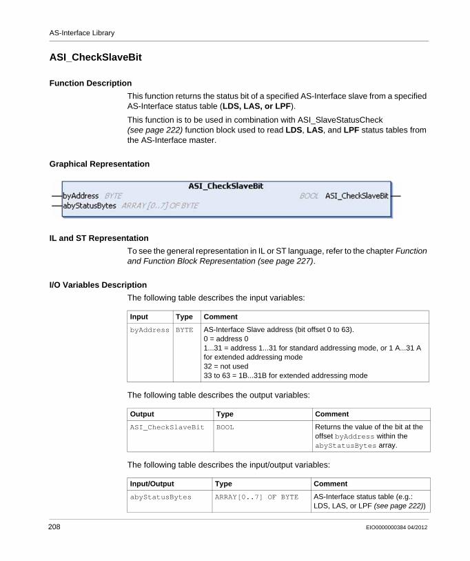
AS-Interface Library
ASI_CheckSlaveBit
Function Description
This function returns the status bit of a specified AS-Interface slave from a specified AS-Interface status table (LDS, LAS, or LPF).
This function is to be used in combination with ASI_SlaveStatusCheck (see page 222) function block used to read LDS, LAS, and LPF status tables from the AS-Interface master.
Graphical Representation
IL and ST Representation
To see the general representation in IL or ST language, refer to the chapter Function and Function Block Representation (see page 227).
I/O Variables Description
The following table describes the input variables:
The following table describes the output variables:
The following table describes the input/output variables:
Input Type Comment
byAddress BYTE AS-Interface Slave address (bit offset 0 to 63).0 = address 01...31 = address 1...31 for standard addressing mode, or 1 A...31 A for extended addressing mode32 = not used33 to 63 = 1B...31B for extended addressing mode
Output Type Comment
ASI_CheckSlaveBit BOOL Returns the value of the bit at the offset byAddress within the abyStatusBytes array.
Input/Output Type Comment
abyStatusBytes ARRAY[0..7] OF BYTE AS-Interface status table (e.g.: LDS, LAS, or LPF (see page 222))
208 EIO0000000384 04/2012
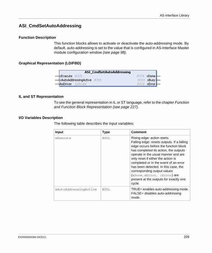
AS-Interface Library
ASI_CmdSetAutoAddressing
Function Description
This function blocks allows to activate or deactivate the auto-addressing mode. By default, auto-addressing is set to the value that is configured in AS-Interface Master module configuration window (see page 98).
Graphical Representation (LD/FBD)
IL and ST Representation
To see the general representation in IL or ST language, refer to the chapter Function and Function Block Representation (see page 227).
I/O Variables Description
The following table describes the input variables:
Input Type Comment
xExecute BOOL Rising edge: action starts.Falling edge: resets outputs. If a falling edge occurs before the function block has completed its action, the outputs operate in the usual manner and are only reset if either the action is completed or in the event of an error has been detected. In this case, the corresponding output values (xDone,xError, iError) are present at the outputs for exactly one cycle.
xAutoAddressingActive BOOL TRUE= enables auto-addressing mode.FALSE= disables auto-addressing mode.
EIO0000000384 04/2012 209
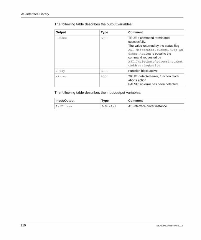
AS-Interface Library
The following table describes the output variables:
The following table describes the input/output variables:
Output Type Comment
xDone BOOL TRUE if command terminated successfully.The value returned by the status flag ASI_MasterStatusCheck.Auto_Address_Assign is equal to the command requested by ASI_CmdSetAutoAddressing.xAutoAddressingActive.
xBusy BOOL Function block active
xError BOOL TRUE: detected error, function block aborts actionFALSE: no error has been detected
Input/Output Type Comment
AsiDriver IoDrvAsi AS-Interface driver instance.
210 EIO0000000384 04/2012
AS-Interface Library
ASI_CmdSetDataExchange
Description
This function enables or disables the data exchange between AS-Interface Master and Slave Modules. The data exchange is active after reset.
Graphical Representation
IL and ST Representation
To see the general representation in IL or ST language, refer to the chapter Function and Function Block Representation (see page 227).
I/O Variables Description
The following table describes the input variables:
Input Type Comment
xExecute BOOL Rising edge: action starts.Falling edge: resets outputs. If a falling edge occurs before the function block has completed its action, the outputs operate in the usual manner and are only reset if either the action is completed or in the event of an error has been detected. In this case, the corresponding output values (xDone,xError, iError) are present at the outputs for exactly one cycle.
xDataExchangeActive BOOL TRUE= enables the data exchange.FALSE= disables the data exchange.
EIO0000000384 04/2012 211
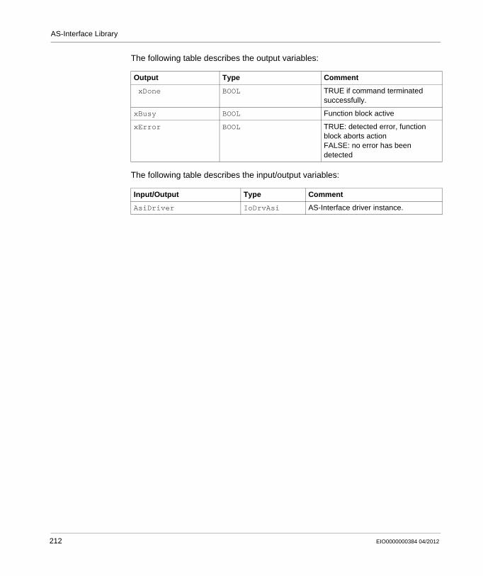
AS-Interface Library
The following table describes the output variables:
The following table describes the input/output variables:
Output Type Comment
xDone BOOL TRUE if command terminated successfully.
xBusy BOOL Function block active
xError BOOL TRUE: detected error, function block aborts actionFALSE: no error has been detected
Input/Output Type Comment
AsiDriver IoDrvAsi AS-Interface driver instance.
212 EIO0000000384 04/2012
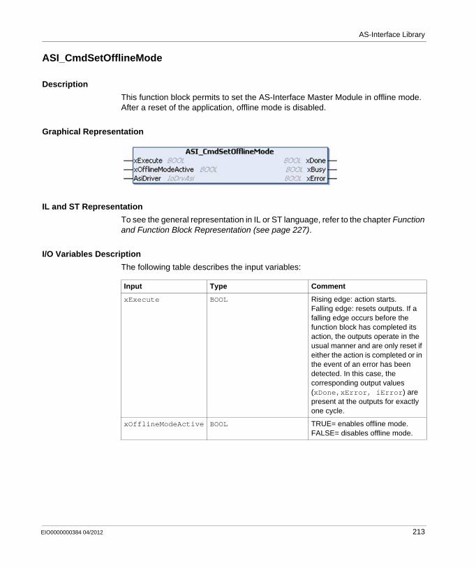
AS-Interface Library
ASI_CmdSetOfflineMode
Description
This function block permits to set the AS-Interface Master Module in offline mode. After a reset of the application, offline mode is disabled.
Graphical Representation
IL and ST Representation
To see the general representation in IL or ST language, refer to the chapter Function and Function Block Representation (see page 227).
I/O Variables Description
The following table describes the input variables:
Input Type Comment
xExecute BOOL Rising edge: action starts.Falling edge: resets outputs. If a falling edge occurs before the function block has completed its action, the outputs operate in the usual manner and are only reset if either the action is completed or in the event of an error has been detected. In this case, the corresponding output values (xDone,xError, iError) are present at the outputs for exactly one cycle.
xOfflineModeActive BOOL TRUE= enables offline mode.FALSE= disables offline mode.
EIO0000000384 04/2012 213
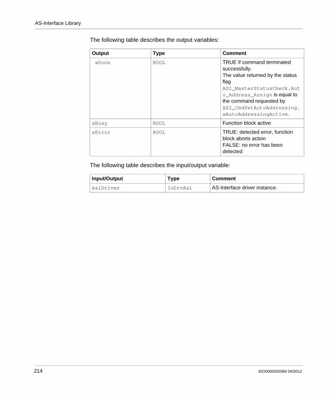
AS-Interface Library
The following table describes the output variables:
The following table describes the input/output variable:
Output Type Comment
xDone BOOL TRUE if command terminated successfully.The value returned by the status flag ASI_MasterStatusCheck.Auto_Address_Assign is equal to the command requested by ASI_CmdSetAutoAddressing.xAutoAddressingActive.
xBusy BOOL Function block active
xError BOOL TRUE: detected error, function block aborts actionFALSE: no error has been detected
Input/Output Type Comment
AsiDriver IoDrvAsi AS-Interface driver instance.
214 EIO0000000384 04/2012
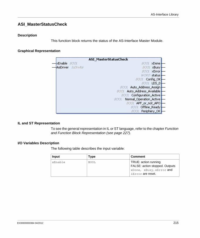
AS-Interface Library
ASI_MasterStatusCheck
Description
This function block returns the status of the AS-Interface Master Module.
Graphical Representation
IL and ST Representation
To see the general representation in IL or ST language, refer to the chapter Function and Function Block Representation (see page 227).
I/O Variables Description
The following table describes the input variable:
Input Type Comment
xEnable BOOL TRUE: action runningFALSE: action stopped. Outputs xDone, xBusy,xError and iError are reset.
EIO0000000384 04/2012 215
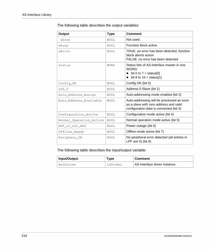
AS-Interface Library
The following table describes the output variables:
The following table describes the input/output variable:
Output Type Comment
xDone BOOL Not used.
xBusy BOOL Function block active
xError BOOL TRUE: an error has been detected, function block aborts actionFALSE: no error has been detected
status WORD Status bits of AS-Interface master in one WORD:
bit 0 to 7 = status[0]bit 8 to 15 = status[1]
Config_OK BOOL Config OK (bit 0)
LDS_0 BOOL Address 0 Slave (bit 1)
Auto_Address_Assign BOOL Auto-addressing mode enabled (bit 2)
Auto_Address_Available BOOL Auto-addressing will be processed as soon as a slave with zero address and valid configuration data is connected (bit 3)
Configuration_Active BOOL Configuration mode active (bit 4)
Normal_Operation_Active BOOL Normal operation mode active (bit 5)
APF_or_not_APO BOOL Power outage (bit 6)
Offline_Ready BOOL Offline mode active (bit 7)
Periphery_OK BOOL No peripheral error detected (all entries in LPF are 0) (bit 8)
Input/Output Type Comment
AsiDriver IoDrvAsi AS-Interface driver instance.
216 EIO0000000384 04/2012
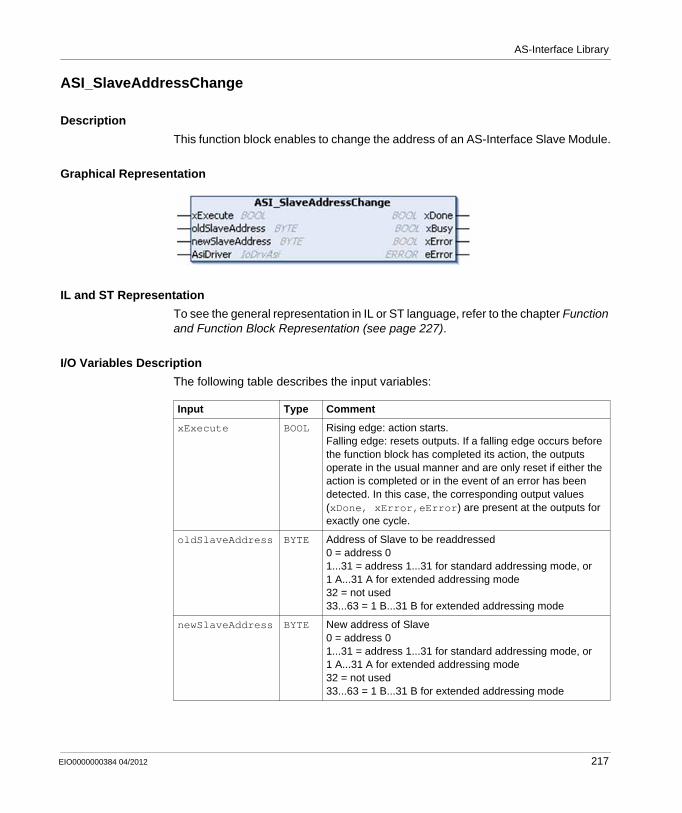
AS-Interface Library
ASI_SlaveAddressChange
Description
This function block enables to change the address of an AS-Interface Slave Module.
Graphical Representation
IL and ST Representation
To see the general representation in IL or ST language, refer to the chapter Function and Function Block Representation (see page 227).
I/O Variables Description
The following table describes the input variables:
Input Type Comment
xExecute BOOL Rising edge: action starts.Falling edge: resets outputs. If a falling edge occurs before the function block has completed its action, the outputs operate in the usual manner and are only reset if either the action is completed or in the event of an error has been detected. In this case, the corresponding output values (xDone, xError,eError) are present at the outputs for exactly one cycle.
oldSlaveAddress BYTE Address of Slave to be readdressed0 = address 01...31 = address 1...31 for standard addressing mode, or 1 A...31 A for extended addressing mode32 = not used33...63 = 1 B...31 B for extended addressing mode
newSlaveAddress BYTE New address of Slave0 = address 01...31 = address 1...31 for standard addressing mode, or 1 A...31 A for extended addressing mode32 = not used33...63 = 1 B...31 B for extended addressing mode
EIO0000000384 04/2012 217
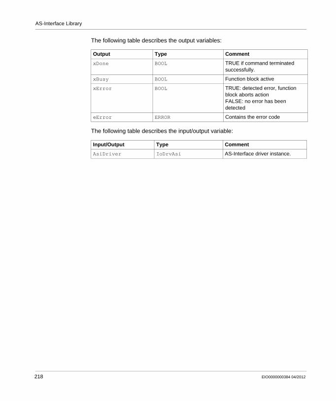
AS-Interface Library
The following table describes the output variables:
The following table describes the input/output variable:
Output Type Comment
xDone BOOL TRUE if command terminated successfully.
xBusy BOOL Function block active
xError BOOL TRUE: detected error, function block aborts actionFALSE: no error has been detected
eError ERROR Contains the error code
Input/Output Type Comment
AsiDriver IoDrvAsi AS-Interface driver instance.
218 EIO0000000384 04/2012
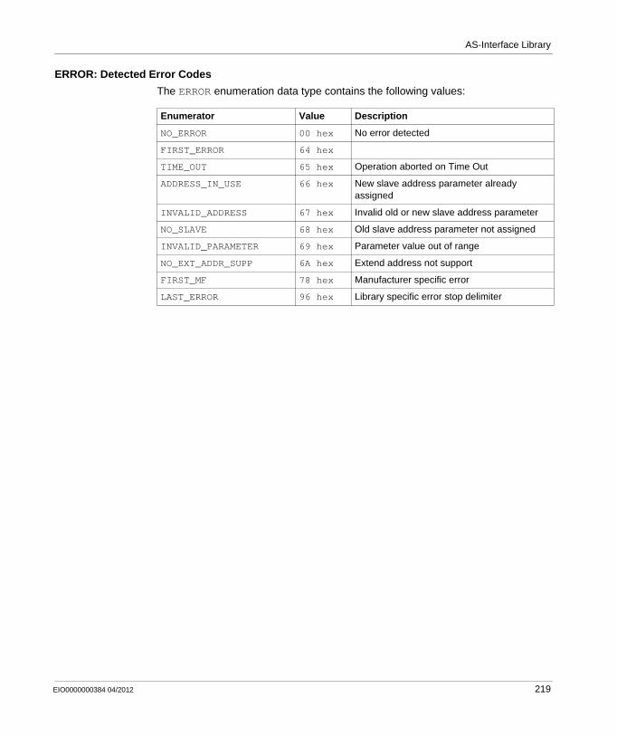
AS-Interface Library
ERROR: Detected Error Codes
The ERROR enumeration data type contains the following values:
Enumerator Value Description
NO_ERROR 00 hex No error detected
FIRST_ERROR 64 hex
TIME_OUT 65 hex Operation aborted on Time Out
ADDRESS_IN_USE 66 hex New slave address parameter already assigned
INVALID_ADDRESS 67 hex Invalid old or new slave address parameter
NO_SLAVE 68 hex Old slave address parameter not assigned
INVALID_PARAMETER 69 hex Parameter value out of range
NO_EXT_ADDR_SUPP 6A hex Extend address not support
FIRST_MF 78 hex Manufacturer specific error
LAST_ERROR 96 hex Library specific error stop delimiter
EIO0000000384 04/2012 219
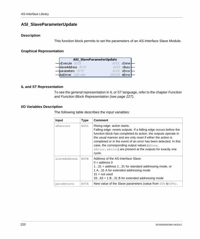
AS-Interface Library
ASI_SlaveParameterUpdate
Description
This function block permits to set the parameters of an AS-Interface Slave Module.
Graphical Representation
IL and ST Representation
To see the general representation in IL or ST language, refer to the chapter Function and Function Block Representation (see page 227).
I/O Variables Description
The following table describes the input variables:
Input Type Comment
xExecute BOOL Rising edge: action starts.Falling edge: resets outputs. If a falling edge occurs before the function block has completed its action, the outputs operate in the usual manner and are only reset if either the action is completed or in the event of an error has been detected. In this case, the corresponding output values (xDone, xError,eError) are present at the outputs for exactly one cycle.
slaveAddress BYTE Address of the AS-Interface Slave.0 = address 01...31 = address 1...31 for standard addressing mode, or 1 A...31 A for extended addressing mode31 = not used33...63 = 1 B...31 B for extended addressing mode
parameters BYTE New value of the Slave parameters (value from 00h to 0Fh).
220 EIO0000000384 04/2012
AS-Interface Library
The following table describes the output variables:
The following table describes the input/output variable:
Output Type Comment
xDone BOOL TRUE if command terminated successfully.
xBusy BOOL Function block active
xError BOOL TRUE: detected error, function block aborts actionFALSE: no error has been detected
eError ERROR (see page 219) Contains the error code.
Input/Output Type Comment
AsiDriver IoDrvAsi AS-Interface driver instance.
EIO0000000384 04/2012 221
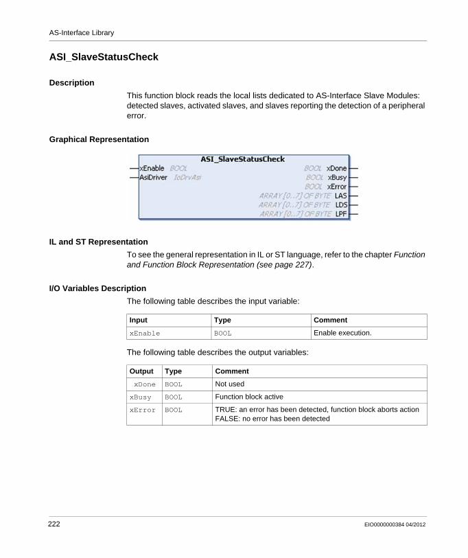
AS-Interface Library
ASI_SlaveStatusCheck
Description
This function block reads the local lists dedicated to AS-Interface Slave Modules: detected slaves, activated slaves, and slaves reporting the detection of a peripheral error.
Graphical Representation
IL and ST Representation
To see the general representation in IL or ST language, refer to the chapter Function and Function Block Representation (see page 227).
I/O Variables Description
The following table describes the input variable:
The following table describes the output variables:
Input Type Comment
xEnable BOOL Enable execution.
Output Type Comment
xDone BOOL Not used
xBusy BOOL Function block active
xError BOOL TRUE: an error has been detected, function block aborts actionFALSE: no error has been detected
222 EIO0000000384 04/2012
AS-Interface Library
The following table describes the input/output variable:
LAS ARRAY[0..7] OF BYTE
List of Activated Slaves (LAS): one bit is set for each activated slave.LAS[0] bit 0 = slave at address 0LAS[0] bit 1 = slave at address 1A...LAS[3] bit 7 = slave at address 31ALAS[4] bit 0 =not usedLAS[4] bit 1 =slave at address 1B...LAS[7] bit 7 =slave at address 31B
LDS ARRAY[0..7] OF BYTE
List of Detected Slaves (LDS): one bit is set for each slave that is detected by the master.LDS[0] bit 0 = slave at address 0LDS[0] bit 1 = slave at address 1A...LDS[3] bit 7 = slave at address 31ALDS[4] bit 0 =not usedLDS[4] bit 1 =slave at address 1B...LDS[7] bit 7 =slave at address 31B
LPF ARRAY[0..7] OF BYTE
List of Peripheral errors (LPF): one bit is set for each slave that has detected a peripheral error.LPF[0] bit 0 = slave at address 0LPF[0] bit 1 = slave at address 1A...LPF[3] bit 7 = slave at address 31ALPF[4] bit 0 =not usedLPF[4] bit 1 =slave at address 1B...LPF[7] bit 7 =slave at address 31B
Input/Output Type Comment
AsiDriver IoDrvAsi AS-Interface driver instance.
Output Type Comment
EIO0000000384 04/2012 223
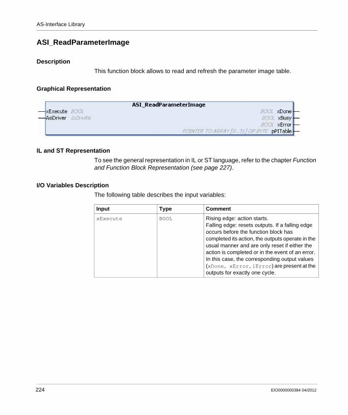
AS-Interface Library
ASI_ReadParameterImage
Description
This function block allows to read and refresh the parameter image table.
Graphical Representation
IL and ST Representation
To see the general representation in IL or ST language, refer to the chapter Function and Function Block Representation (see page 227).
I/O Variables Description
The following table describes the input variables:
Input Type Comment
xExecute BOOL Rising edge: action starts.Falling edge: resets outputs. If a falling edge occurs before the function block has completed its action, the outputs operate in the usual manner and are only reset if either the action is completed or in the event of an error. In this case, the corresponding output values (xDone, xError,iError) are present at the outputs for exactly one cycle.
224 EIO0000000384 04/2012
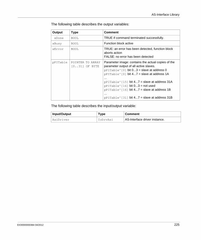
AS-Interface Library
The following table describes the output variables:
The following table describes the input/output variable:
Output Type Comment
xDone BOOL TRUE if command terminated successfully.
xBusy BOOL Function block active
xError BOOL TRUE: an error has been detected, function block aborts actionFALSE: no error has been detected
pPITable POINTER TO ARRAY [0..31] OF BYTE
Parameter image: contains the actual copies of the parameter output of all active slaves.pPITable^[0] bit 0...3 = slave at address 0pPITable^[0] bit 4...7 = slave at address 1A...pPITable^[15] bit 4...7 = slave at address 31ApPITable^[16] bit 0...3 = not usedpPITable^[16] bit 4...7 = slave at address 1B...pPITable^[31] bit 4...7 = slave at address 31B
Input/Output Type Comment
AsiDriver IoDrvAsi AS-Interface driver instance.
EIO0000000384 04/2012 225

AS-Interface Library
226 EIO0000000384 04/2012
EIO0000000384 04/2012
B
Modicon M238 Logic Controller
Function and Function Block Representation
EIO0000000384 04/2012
Function and Function Block Representation
Overview
Each function can be represented in the following languages:IL: Instruction ListST: Structured TextLD: Ladder DiagramFBD: Function Block DiagramCFC: Continuous Function Chart
This chapter provides functions and function blocks representation examples and explains how to use them for IL and ST languages.
What’s in this Chapter?
This chapter contains the following topics:
Topic Page
Differences Between a Function and a Function Block 228
How to Use a Function or a Function Block in IL Language 229
How to Use a Function or a Function Block in ST Language 232
227
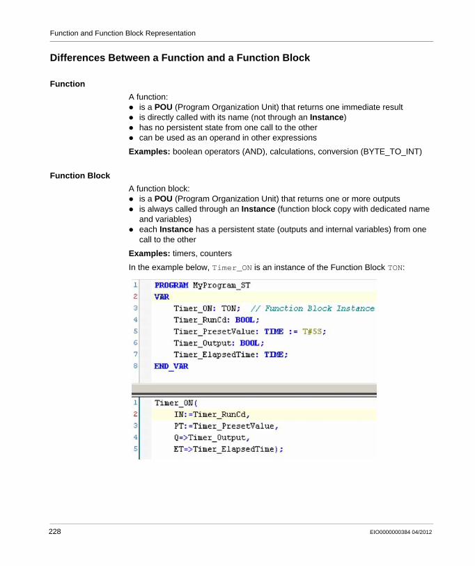
Function and Function Block Representation
Differences Between a Function and a Function Block
Function
A function:is a POU (Program Organization Unit) that returns one immediate resultis directly called with its name (not through an Instance)has no persistent state from one call to the othercan be used as an operand in other expressions
Examples: boolean operators (AND), calculations, conversion (BYTE_TO_INT)
Function Block
A function block:is a POU (Program Organization Unit) that returns one or more outputsis always called through an Instance (function block copy with dedicated name and variables)each Instance has a persistent state (outputs and internal variables) from one call to the other
Examples: timers, counters
In the example below, Timer_ON is an instance of the Function Block TON:
228 EIO0000000384 04/2012
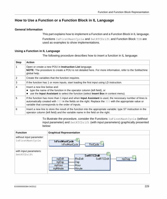
Function and Function Block Representation
How to Use a Function or a Function Block in IL Language
General Information
This part explains how to implement a Function and a Function Block in IL language.
Functions IsFirstMastCycle and SetRTCDrift and Function Block TON are used as examples to show implementations.
Using a Function in IL Language
The following procedure describes how to insert a function in IL language:
To illustrate the procedure, consider the Functions IsFirstMastCycle (without input parameter) and SetRTCDrift (with input parameters) graphically presented below:
Step Action
1 Open or create a new POU in Instruction List language.NOTE: The procedure to create a POU is not detailed here. For more information, refer to the SoMachine global help.
2 Create the variables that the function requires.
3 If the function has 1 or more inputs, start loading the first input using LD instruction.
4 Insert a new line below and:type the name of the function in the operator column (left field), oruse the Input Assistant to select the function (select Insert Box in context menu).
5 If the function has more than 1 input and when Input Assistant is used, the necessary number of lines is automatically created with ??? in the fields on the right. Replace the ??? with the appropriate value or variable that corresponds to the order of inputs.
6 Insert a new line to store the result of the function into the appropriate variable: type ST instruction in the operator column (left field) and the variable name in the field on the right.
Function Graphical Representation
without input parameter:IsFirstMastCycle
with input parameters:SetRTCDrift
EIO0000000384 04/2012 229
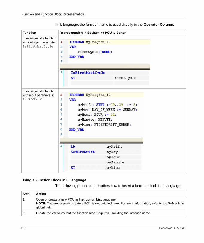
Function and Function Block Representation
In IL language, the function name is used directly in the Operator Column:
Using a Function Block in IL language
The following procedure describes how to insert a function block in IL language:
Function Representation in SoMachine POU IL Editor
IL example of a function without input parameter:IsFirstMastCycle
IL example of a function with input parameters:SetRTCDrift
Step Action
1 Open or create a new POU in Instruction List language.NOTE: The procedure to create a POU is not detailed here. For more information, refer to the SoMachine global help.
2 Create the variables that the function block requires, including the instance name.
230 EIO0000000384 04/2012
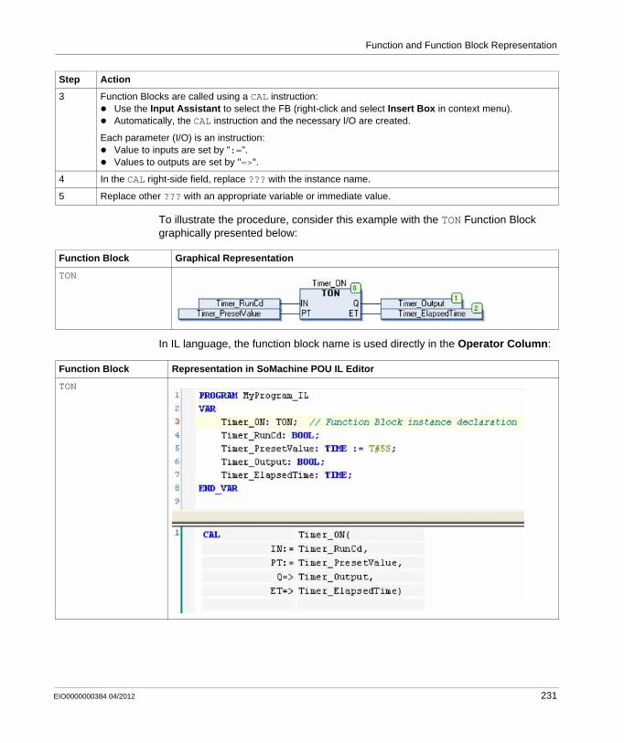
Function and Function Block Representation
To illustrate the procedure, consider this example with the TON Function Block graphically presented below:
In IL language, the function block name is used directly in the Operator Column:
3 Function Blocks are called using a CAL instruction:Use the Input Assistant to select the FB (right-click and select Insert Box in context menu).Automatically, the CAL instruction and the necessary I/O are created.
Each parameter (I/O) is an instruction:Value to inputs are set by ":=".Values to outputs are set by "=>".
4 In the CAL right-side field, replace ??? with the instance name.
5 Replace other ??? with an appropriate variable or immediate value.
Step Action
Function Block Graphical Representation
TON
Function Block Representation in SoMachine POU IL Editor
TON
EIO0000000384 04/2012 231
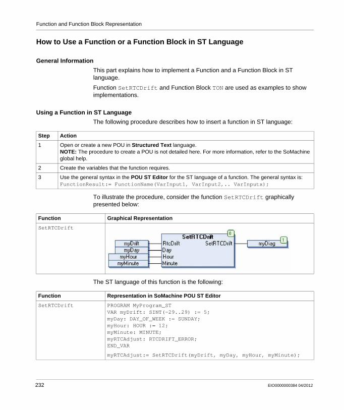
Function and Function Block Representation
How to Use a Function or a Function Block in ST Language
General Information
This part explains how to implement a Function and a Function Block in ST language.
Function SetRTCDrift and Function Block TON are used as examples to show implementations.
Using a Function in ST Language
The following procedure describes how to insert a function in ST language:
To illustrate the procedure, consider the function SetRTCDrift graphically presented below:
The ST language of this function is the following:
Step Action
1 Open or create a new POU in Structured Text language.NOTE: The procedure to create a POU is not detailed here. For more information, refer to the SoMachine global help.
2 Create the variables that the function requires.
3 Use the general syntax in the POU ST Editor for the ST language of a function. The general syntax is:FunctionResult:= FunctionName(VarInput1, VarInput2,.. VarInputx);
Function Graphical Representation
SetRTCDrift
Function Representation in SoMachine POU ST Editor
SetRTCDrift PROGRAM MyProgram_STVAR myDrift: SINT(-29..29) := 5;myDay: DAY_OF_WEEK := SUNDAY;myHour: HOUR := 12;myMinute: MINUTE;myRTCAdjust: RTCDRIFT_ERROR;END_VAR
myRTCAdjust:= SetRTCDrift(myDrift, myDay, myHour, myMinute);
232 EIO0000000384 04/2012
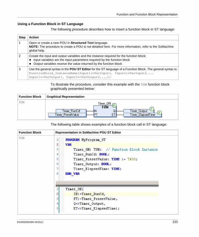
Function and Function Block Representation
Using a Function Block in ST Language
The following procedure describes how to insert a function block in ST language:
To illustrate the procedure, consider this example with the TON function block graphically presented below:
The following table shows examples of a function block call in ST language:
Step Action
1 Open or create a new POU in Structured Text language.NOTE: The procedure to create a POU is not detailed here. For more information, refer to the SoMachine global help.
2 Create the input and output variables and the instance required for the function block:Input variables are the input parameters required by the function blockOutput variables receive the value returned by the function block
3 Use the general syntax in the POU ST Editor for the ST language of a Function Block. The general syntax is:FunctionBlock_InstanceName(Input1:=VarInput1, Input2:=VarInput2,... Ouput1=>VarOutput1, Ouput2=>VarOutput2,...);
Function Block Graphical Representation
TON
Function Block Representation in SoMachine POU ST Editor
TON
EIO0000000384 04/2012 233

Function and Function Block Representation
234 EIO0000000384 04/2012
EIO0000000384 04/2012
C
Modicon M238 Logic Controller
Functions to get/set serial line configuration in user program
EIO0000000384 04/2012
Functions to Get/Set Serial Line Configuration in User Program
Overview
This section describes the functions to get/set the serial line configuration in your program.
To use these functions, you must add the M2xx Communication library.
For further information on adding a library, refer to the SoMachine Programming Guide (see SoMachine, Programming Guide).
What’s in this Chapter?
This chapter contains the following topics:
Topic Page
GetSerialConf: Get the Serial Line Configuration 236
SetSerialConf: Change the Serial Line Configuration 237
SERIAL_CONF: Structure of the Serial Line Configuration Data Type 239
235
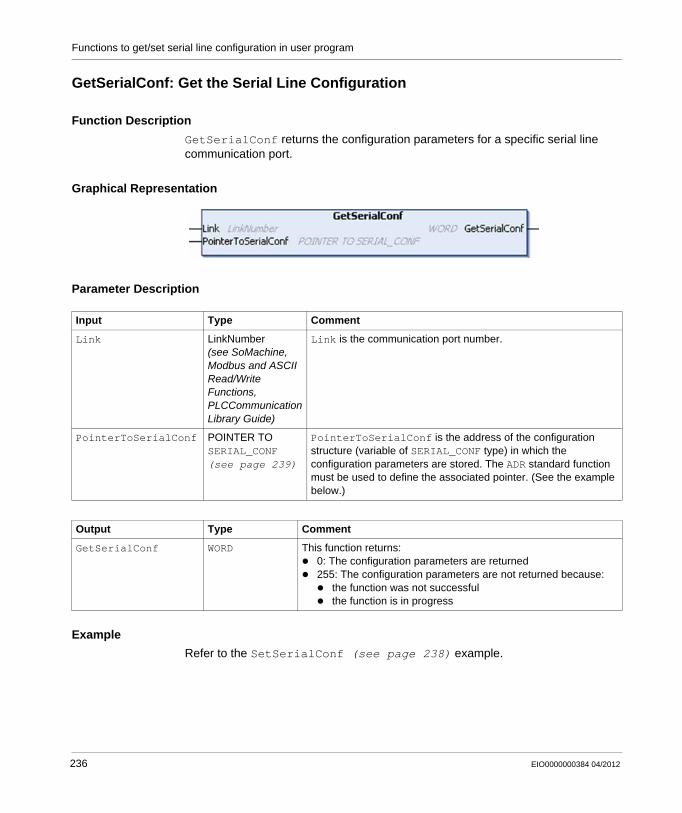
Functions to get/set serial line configuration in user program
GetSerialConf: Get the Serial Line Configuration
Function Description
GetSerialConf returns the configuration parameters for a specific serial line communication port.
Graphical Representation
Parameter Description
Example
Refer to the SetSerialConf (see page 238) example.
Input Type Comment
Link LinkNumber (see SoMachine, Modbus and ASCII Read/Write Functions, PLCCommunication Library Guide)
Link is the communication port number.
PointerToSerialConf POINTER TO SERIAL_CONF (see page 239)
PointerToSerialConf is the address of the configuration structure (variable of SERIAL_CONF type) in which the configuration parameters are stored. The ADR standard function must be used to define the associated pointer. (See the example below.)
Output Type Comment
GetSerialConf WORD This function returns:0: The configuration parameters are returned255: The configuration parameters are not returned because:
the function was not successfulthe function is in progress
236 EIO0000000384 04/2012
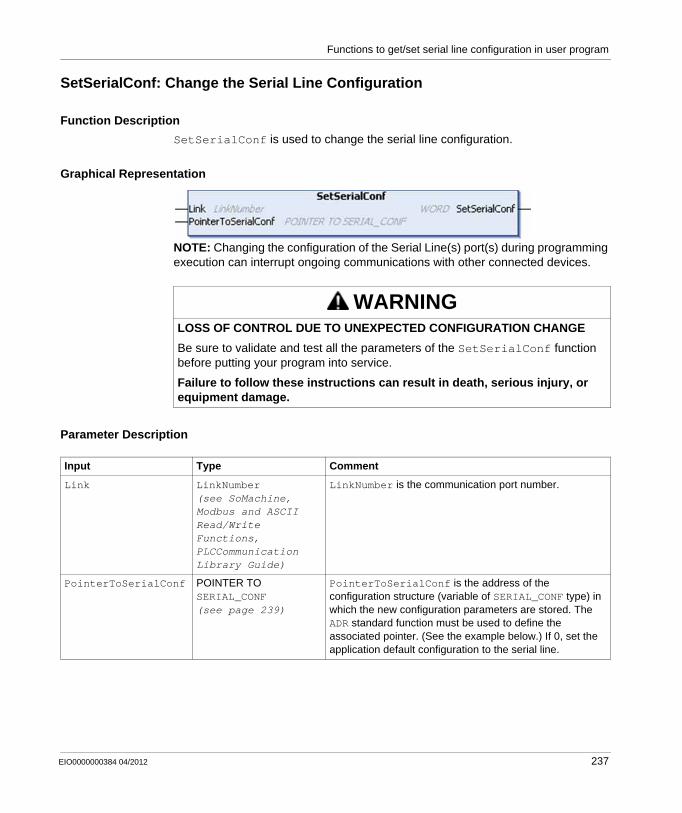
Functions to get/set serial line configuration in user program
SetSerialConf: Change the Serial Line Configuration
Function Description
SetSerialConf is used to change the serial line configuration.
Graphical Representation
NOTE: Changing the configuration of the Serial Line(s) port(s) during programming execution can interrupt ongoing communications with other connected devices.
Parameter Description
WARNINGLOSS OF CONTROL DUE TO UNEXPECTED CONFIGURATION CHANGE
Be sure to validate and test all the parameters of the SetSerialConf function before putting your program into service.
Failure to follow these instructions can result in death, serious injury, or equipment damage.
Input Type Comment
Link LinkNumber (see SoMachine, Modbus and ASCII Read/Write Functions, PLCCommunication Library Guide)
LinkNumber is the communication port number.
PointerToSerialConf POINTER TO SERIAL_CONF (see page 239)
PointerToSerialConf is the address of the configuration structure (variable of SERIAL_CONF type) in which the new configuration parameters are stored. The ADR standard function must be used to define the associated pointer. (See the example below.) If 0, set the application default configuration to the serial line.
EIO0000000384 04/2012 237
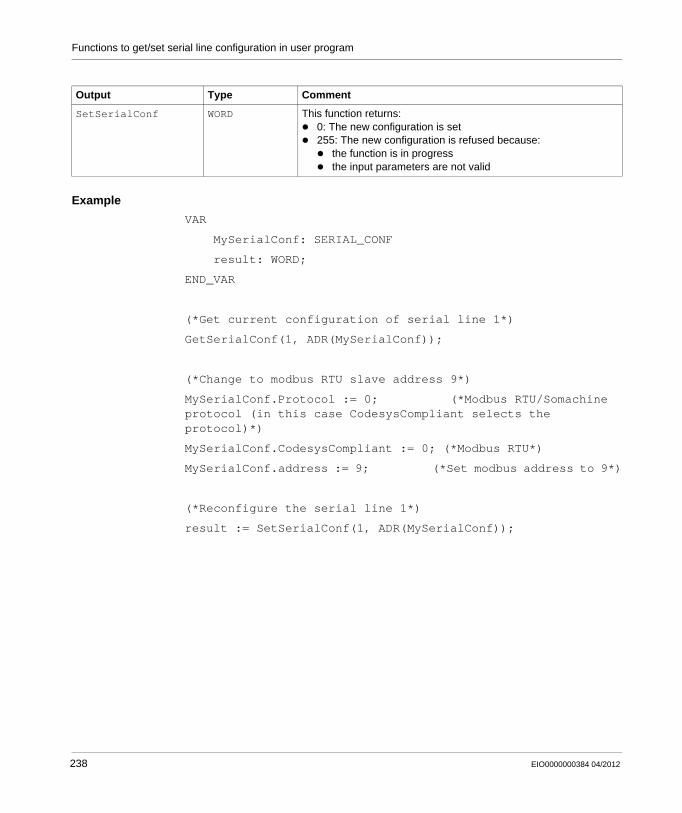
Functions to get/set serial line configuration in user program
Example
VAR
MySerialConf: SERIAL_CONF
result: WORD;
END_VAR
(*Get current configuration of serial line 1*)
GetSerialConf(1, ADR(MySerialConf));
(*Change to modbus RTU slave address 9*)
MySerialConf.Protocol := 0; (*Modbus RTU/Somachine protocol (in this case CodesysCompliant selects the protocol)*)
MySerialConf.CodesysCompliant := 0; (*Modbus RTU*)
MySerialConf.address := 9; (*Set modbus address to 9*)
(*Reconfigure the serial line 1*)
result := SetSerialConf(1, ADR(MySerialConf));
Output Type Comment
SetSerialConf WORD This function returns:0: The new configuration is set255: The new configuration is refused because:
the function is in progressthe input parameters are not valid
238 EIO0000000384 04/2012
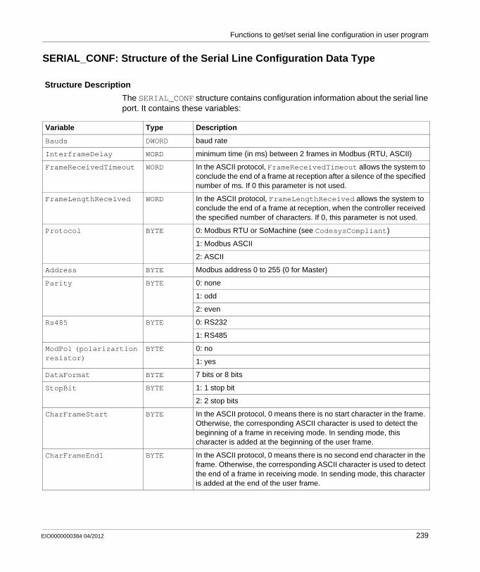
Functions to get/set serial line configuration in user program
SERIAL_CONF: Structure of the Serial Line Configuration Data Type
Structure Description
The SERIAL_CONF structure contains configuration information about the serial line port. It contains these variables:
Variable Type Description
Bauds DWORD baud rate
InterframeDelay WORD minimum time (in ms) between 2 frames in Modbus (RTU, ASCII)
FrameReceivedTimeout WORD In the ASCII protocol, FrameReceivedTimeout allows the system to conclude the end of a frame at reception after a silence of the specified number of ms. If 0 this parameter is not used.
FrameLengthReceived WORD In the ASCII protocol, FrameLengthReceived allows the system to conclude the end of a frame at reception, when the controller received the specified number of characters. If 0, this parameter is not used.
Protocol BYTE 0: Modbus RTU or SoMachine (see CodesysCompliant)
1: Modbus ASCII
2: ASCII
Address BYTE Modbus address 0 to 255 (0 for Master)
Parity BYTE 0: none
1: odd
2: even
Rs485 BYTE 0: RS232
1: RS485
ModPol (polarizartion resistor)
BYTE 0: no
1: yes
DataFormat BYTE 7 bits or 8 bits
StopBit BYTE 1: 1 stop bit
2: 2 stop bits
CharFrameStart BYTE In the ASCII protocol, 0 means there is no start character in the frame. Otherwise, the corresponding ASCII character is used to detect the beginning of a frame in receiving mode. In sending mode, this character is added at the beginning of the user frame.
CharFrameEnd1 BYTE In the ASCII protocol, 0 means there is no second end character in the frame. Otherwise, the corresponding ASCII character is used to detect the end of a frame in receiving mode. In sending mode, this character is added at the end of the user frame.
EIO0000000384 04/2012 239
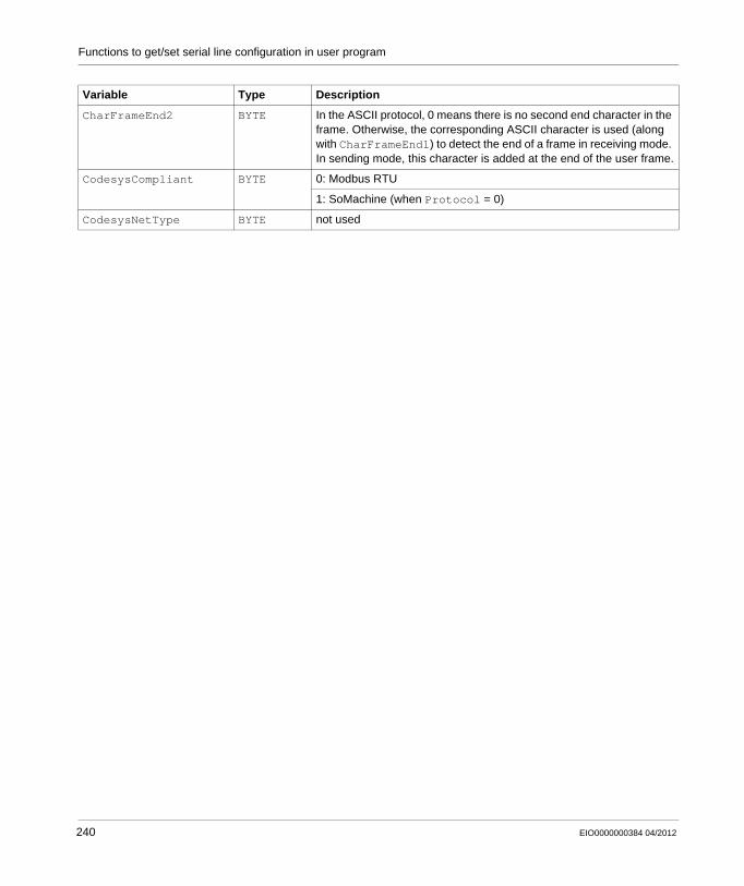
Functions to get/set serial line configuration in user program
CharFrameEnd2 BYTE In the ASCII protocol, 0 means there is no second end character in the frame. Otherwise, the corresponding ASCII character is used (along with CharFrameEnd1) to detect the end of a frame in receiving mode. In sending mode, this character is added at the end of the user frame.
CodesysCompliant BYTE 0: Modbus RTU
1: SoMachine (when Protocol = 0)
CodesysNetType BYTE not used
Variable Type Description
240 EIO0000000384 04/2012
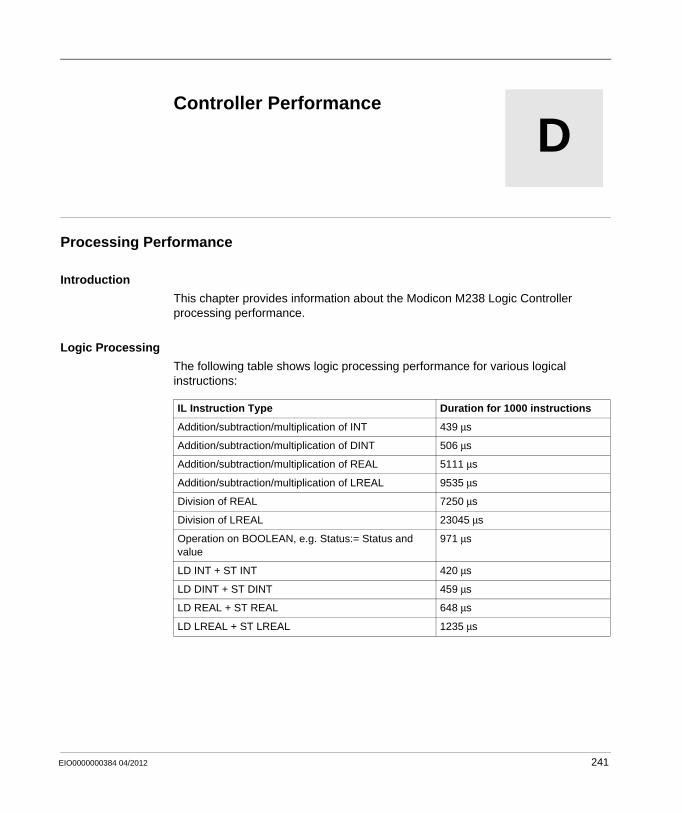
EIO0000000384 04/2012
D
Modicon M238 Logic Controller
M238 - Controller Performance)
EIO0000000384 04/2012
Controller Performance
Processing Performance
Introduction
This chapter provides information about the Modicon M238 Logic Controller processing performance.
Logic Processing
The following table shows logic processing performance for various logical instructions:
IL Instruction Type Duration for 1000 instructions
Addition/subtraction/multiplication of INT 439 μs
Addition/subtraction/multiplication of DINT 506 μs
Addition/subtraction/multiplication of REAL 5111 μs
Addition/subtraction/multiplication of LREAL 9535 μs
Division of REAL 7250 μs
Division of LREAL 23045 μs
Operation on BOOLEAN, e.g. Status:= Status and value
971 μs
LD INT + ST INT 420 μs
LD DINT + ST DINT 459 μs
LD REAL + ST REAL 648 μs
LD LREAL + ST LREAL 1235 μs
241
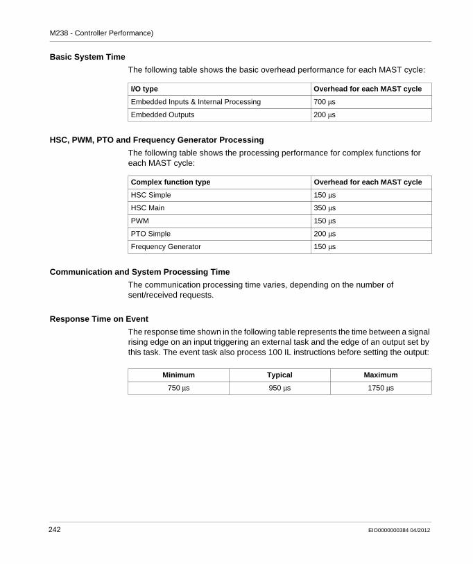
M238 - Controller Performance)
Basic System Time
The following table shows the basic overhead performance for each MAST cycle:
HSC, PWM, PTO and Frequency Generator Processing
The following table shows the processing performance for complex functions for each MAST cycle:
Communication and System Processing Time
The communication processing time varies, depending on the number of sent/received requests.
Response Time on Event
The response time shown in the following table represents the time between a signal rising edge on an input triggering an external task and the edge of an output set by this task. The event task also process 100 IL instructions before setting the output:
I/O type Overhead for each MAST cycle
Embedded Inputs & Internal Processing 700 μs
Embedded Outputs 200 μs
Complex function type Overhead for each MAST cycle
HSC Simple 150 μs
HSC Main 350 μs
PWM 150 μs
PTO Simple 200 μs
Frequency Generator 150 μs
Minimum Typical Maximum
750 μs 950 μs 1750 μs
242 EIO0000000384 04/2012
Modicon M238 Logic Controller
Glossary
EIO0000000384 04/2012
Glossary
A
application sourceThe application source file can be uploaded to the PC to reopen a SoMachine project. This source file can support a full SoMachine project (for example, one that includes HMI application).
ARPThe address resolution protocol is the IP network layer protocol for Ethernet that maps an IP address to a MAC (hardware) address.
ASCIIThe american standard code for information interchange is a communication protocol for representing alphanumeric characters (letters, numbers, and certain graphic and control characters).
B
BOOTPThe bootstrap protocol is a UDP network protocol that can be used by a network client to automatically obtain an IP address (and possibly other data) from a server. The client identifies itself to the server using the client’s MAC address. The server—which maintains a pre-configured table of client device MAC addresses and associated IP addresses—sends the client its pre-configured IP address. BOOTP was originally used as a method that enabled diskless hosts to be remotely booted over a network. The BOOTP process assigns an infinite lease of an IP address. The BOOTP service utilizes UDP ports 67 and 68.
EIO0000000384 04/2012 243
Glossary
C
CANThe controller area network protocol (ISO 11898) for serial bus networks is designed for the interconnection of smart devices (from multiple manufacturers) in smart systems for real-time industrial applications. CAN multi-master systems ensure high data integrity through the implementation of broadcast messaging and advanced diagnostic mechanisms. Originally developed for use in automobiles, CAN is now used in a variety of industrial automation control environments.
CANmotionCANmotion is a CANopen-based motion bus with an additional mechanism that provides synchronization between the motion controller and the drives.
CANopenCANopen is an open industry-standard communication protocol and device profile specification.
CFCThe continuous function chart (an extension of the IEC61131-3 standard) is a graphical programming language that works like a flowchart. By adding simple logicals blocks (AND, OR, etc.), each function or function block in the program is represented in this graphical format. For each block, the inputs are on the left and the outputs on the right. Block outputs can be linked to inputs of other blocks in order to create complex expressions.
CiACAN in automation is a non-profit group of manufacturers and users dedicated to developing and supporting CAN-based higher layer protocols.
CIPWhen the common industrial protocol is implemented in a network’s application layer, it can communicate seamlessly with other CIP-based networks without regard to the protocol. For example, the implementation of CIP in the application layer of an Ethernet TCP/IP network creates an EtherNet/IP environment. Similarly, CIP in the application layer of a CAN network creates a DeviceNet environment. In that case, devices on the EtherNet/IP network can communicate with devices on the DeviceNet network through CIP bridges or routers.
244 EIO0000000384 04/2012
Glossary
controllerA controller (or “programmable logic controller,” or “programmable controller”) is used to automate industrial processes.
cyclic taskThe cyclic scan time has a fixed duration (interval) specified by the user. If the current scan time is shorter than the cyclic scan time, the controller waits until the cyclic scan time has elapsed before starting a new scan.
D
data logThe controller logs events relative to the user application in a data log.
DHCPThe dynamic host configuration protocol is an advanced extension of BOOTP. DHCP is a more advanced, but both DHCP and BOOTP are common. (DHCP can handle BOOTP client requests.)
E
EEPROMElectrically erasable programmable read-only memory is a type of non-volatile memory used to store data that must be saved when power is removed.
EIA rackAn electronic industries alliance rack is a standardized (EIA 310-D, IEC 60297 and DIN 41494 SC48D) system for mounting various electronic modules in a stack or rack that is 19 inches (482.6 mm) wide.
EtherNet/IPThe ethernet industrial protocol is an open communications protocol for manufacturing automation solutions in industrial systems. EtherNet/IP is in a family of networks that implements Common Industrial Protocol at its upper layers. The supporting organization (ODVA) specifies EtherNet/IP to accomplish global adaptability and media independence.
EIO0000000384 04/2012 245
Glossary
expansion busThe expansion bus is an electronic communication bus between expansion modules and a CPU.
expansion I/O moduleAn expansion input or output module is either a digital or analog module that adds additional I/O to the base controller.
expert I/OExpert I/Os are dedicated modules or channels for advanced features. These features are generally embedded in the module in order to not use the resources of the PLC Controller and to allow a fast response time, depending of the feature. Regarding the function, it could be considered as a “stand alone” module, because the function is independent of the Controller processing cycle, it just exchanges some information with the Controller CPU.
F
FAST I/OFAST I/Os are specific I/Os with some electrical features (response time, for example) but the treatment of these channels is done by the Controller CPU.
FBA function block performs a specific automation function, such as speed control, interval control, or counting. A function block comprises configuration data and a set of operating parameters.
FBDA function block diagram is a graphically oriented programming language, compliant with IEC 61131-3. It works with a list of networks whereby each network contains a graphical structure of boxes and connection lines which represents either a logical or arithmetic expression, the call of a function block, a jump, or a return instruction.
FGfrequency generator
firmwareThe firmware represents the operating system on a controller.
246 EIO0000000384 04/2012
Glossary
Flash MemoryFlash memory is nonvolatile memory that can be overwritten. It is stored on a special EEPROM that can be erased and reprogrammed.
FTPFile transfer protocol is a standard network protocol (built on a client-server architecture), to exchange and manipulate files over TCP/IP based networks.
function blockSee FB.
function block diagramSee FBD.
G
GVLThe global variable list manages global variables that are available in every application POU.
H
HSChigh-speed counter
I
ICMPThe internet control message protocol reports errors and provides information related to datagram processing.
EIO0000000384 04/2012 247
Glossary
IEC 61131-3The IEC 61131-3 is an international electrotechnical commission standard for industrial automation equipment (like controllers). IEC 61131-3 deals with controller programming languages and defines 2 graphical and 2 textual programming language standards:
graphical: ladder diagram, function block diagramtextual: structured text, instruction list
ILA program written in the instruction list language is composed of a series of instructions executed sequentially by the controller. Each instruction includes a line number, an instruction code, and an operand. (IL is IEC 61131-3 compliant.)
instruction list languageRefer to IL.
IPThe internet protocol is part of the TCP/IP protocol family that tracks the Internet addresses of devices, routes outgoing messages, and recognizes incoming messages.
IP 20Ingress protection rating according to IEC 60529. IP20 modules are protected against ingress and contact of objects larger than 12.5 mm. The module is not protected against harmful ingress of water.
L
Ladder Diagram LanguageSee LD.
latching inputA latching input module interfaces with devices that transmit messages in short pulses. Incoming pulses are captured and recorded for later examination by the application.
248 EIO0000000384 04/2012
Glossary
LDA program in the ladder diagram language includes a graphical representation of instructions of a controller program with symbols for contacts, coils, and blocks in a series of rungs executed sequentially by a controller. IEC 61131-3 compliant.
located variableA located variable has an address. (See unlocated variable.)
M
MAC addressThe media access control address is a unique 48-bit number associated with a specific piece of hardware. The MAC address is programmed into each network card or device when it is manufactured.
MASTA master (MAST) task is a processor task that is run through its programming software. The MAST task has two sections:
IN: Inputs are copied to the IN section before execution of the MAST task.OUT: Outputs are copied to the OUT section after execution of the MAST task.
master/slaveThe single direction of control in a network that implements the master/slave model is always from a master device or process to one or more slave devices.
MIBThe management information base is an object database that is monitored by a network management system like SNMP. SNMP monitors devices that are defined by their MIBs. Schneider has obtained a private MIB, groupeschneider (3833).
ModbusThe Modbus communication protocol allows communications between many devices connected to the same network.
EIO0000000384 04/2012 249
Glossary
N
NEMAThe national electrical manufacturers association publishes standards for the performance of various classes of electrical enclosures. The NEMA standards cover corrosion resistance, ability to protect from rain and submersion, etc. For IEC member countries, the IEC 60529 standard classifies the ingress protection rating for enclosures.
networkA network includes interconnected devices that share a common data path and protocol for communications.
nodeA node is an addressable device on a communication network.
O
ODVAThe open deviceNet vendors association supports the family of network technologies that are built on CIP (EtherNet/IP, DeviceNet, and CompoNet).
OSOperating system. Can be used for Firmware that can be uploaded/downloaded by the user.
P
PDOA process data object is transmitted as an unconfirmed broadcast message or sent from a producer device to a consumer device in a CAN-based network. The transmit PDO from the producer device has a specific identifier that corresponds to the receive PDO of the consumer devices.
250 EIO0000000384 04/2012
Glossary
periodic executionThe master task is executed either cyclically or periodically. In periodic mode, you determine a specific time (period) in which the master task must be executed. If it is executed under this time, a waiting time is generated before the next cycle. If it is executed over this time, a control system indicates the overrun. If the overrun is too high, the controller is stopped.
persistent dataValue of persistent data that will be used at next application change or cold start. Only get re-initialized at a reboot of the controller or reset origin. Especially they maintain their values after a download.
PLCopenThe PLCopen standard brings efficiency, flexibility, and manufacturer independence to the automation and control industry through the standardization of tools, libraries, and modular approaches to software programming.
post configurationPost-configuration files contain machine-independent parameters, including:
machine namedevice name or IP addressModbus serial line addressrouting table
POUA program organization unit includes a variable declaration in source code and the corresponding instruction set. POUs facilitate the modular reuse of software programs, functions, and function blocks. Once declared, POUs are available to one another. SoMachine programming requires the utilization of POUs.
protocolA protocol is a convention or standard that controls or enables the connection, communication, and data transfer between two computing endpoints.
PTOPulse train outputs are used to control for instance stepper motors in open loop.
EIO0000000384 04/2012 251
Glossary
PWMPulse width modulation is used for regulation processes (e.g. actuators for temperature control) where a pulse signal is modulated in its length. For these kind of signals, transistor outputs are used.
R
real-time clock (RTC)See RTC
reflex outputIn a counting mode, the high speed counter’s current value is measured against its configured thresholds to determine the state of these dedicated outputs.
retained dataA retained data value is used in the next power-on or warm start. The value is retained even after an uncontrolled shutdown of the controller or a normal switch-off of the controller.
RFIDRadio-frequency identification is an automatic identification method that relies on the storage and remote retrieval of data using RFID tags or transponders.
RPDOA receive PDO sends data to a device in a CAN-based network.
RTCThe real-time clock option keeps the time for a limited amount of time even when the controller is not powered.
S
scanA controller’s scanning program performs 3 basic functions: [1] It reads inputs and places these values in memory; [2] it executes the application program 1 instruction at a time and stores results in memory; [3] It uses the results to update outputs.
252 EIO0000000384 04/2012
Glossary
SDOA service data object message is used by the fieldbus master to access (read/write) the object directories of network nodes in CAN-based networks. SDO types include service SDOs (SSDOs) and client SDOs (CSDOs).
sequential function chartSee SFC.
SFCA program written in the sequential function chart language can be used for processes that can be split into steps. SFC is composed of steps with associated actions, transitions with associated logic condition, and directed links between steps and transitions. (The SFC standard is defined in IEC 848. It is IEC 61131-3 compliant.)
SNMPThe simple network management protocol can control a network remotely by polling the devices for their status, performing security tests, and viewing information relating to data transmission. It can also be used to manage software and databases remotely. The protocol also permits active management tasks, such as modifying and applying a new configuration
Structured TextA program written in the structured text (ST) language includes complex statements and nested instructions (such as iteration loops, conditional executions, or functions). ST is compliant with IEC 61131-3.
symbolA symbol is a string of a maximum of 32 alphanumeric characters, of which the first character is alphabetic. It allows you to personalize a controller object to facilitate the maintainability of the application.
system variableA system variable structure provides controller data and diagnostic information and allows sending commands to the controller.
EIO0000000384 04/2012 253
Glossary
T
taskA group of sections and subroutines, executed cyclically or periodically for the MAST task, or periodically for the FAST task.
A task possesses a level of priority and is linked to inputs and outputs of the controller. These I/O are refreshed in consequence.
A controller can have several tasks.
TCPA transmission control protocol is a connection-based transport layer protocol that provides a reliable simultaneous bi-directional transmission of data. TCP is part of the TCP/IP protocol suite.
threshold outputThreshold outputs are controlled directly by the HSC according to the settings established during configuration.
TPDOA transmit PDO reads data from a device in a CAN-based system.
U
UDPThe user datagram protocol is a connectionless mode protocol (defined by IETF RFC 768) in which messages are delivered in a datagram (data telegram) to a destination computer on an IP network. The UDP protocol is typically bundled with the Internet Protocol. UDP/IP messages do not expect a response, and are therefore ideal for applications in which dropped packets do not require retransmission (such as streaming video and networks that demand real-time performance).
unlocated variableAn unlocated variable does not have an address. (See located variable.)
254 EIO0000000384 04/2012
Modicon M238 Logic Controller
Index
EIO0000000384 04/2012
CBA
IndexAAS-Interface Library
ASI_CheckSlaveBit, 208ASI_CmdSetAutoAddressing, 209ASI_CmdSetOfflineMode, 213ASI_MasterStatusCheck, 215ASI_ReadParameterImage, 224ASI_SlaveAddressChange, 217ASI_SlaveParameterUpdate, 220ASI_SlaveStatusCheck, 222
AS-Interface Library ASI_CmdSetDataExchange, 211
AS-Interface V2 FieldbusAdd a Slave with Scan Devices, 103Add an AS-Interface Slave, 100Add an Slave With Catalog, 100Add AS-Interface Module, 95Automatic Slave Addressing, 112Configure an AS-Interface Master, 97Configure an AS-Interface Slave, 109Diagnostic, 116General Functional Description, 91Inoperative Slave, 121Manually Add a Generic Slave, 106Modification of Slave Address, 113Presentation, 90Programming, 120Software Setup Principle, 94
EIO0000000384 04/2012
CController Configuration
Applications, 68PLC Settings, 69Services, 71
DDownload application, 61
EEmbedded Functions Configuration
Embedded HSC Configuration, 74Embedded I/O Configuration, 76Embedded PTO_PWM Configuration, 80
Ethernet Gateway ConfigurationConnection and Configuration of the Ethernet Gateway, 149
Expansion ModuleAdding Expansion Module, 83Configure Expansion Module, 83
255
Index
FFAQ, 203features
key features, 13Firmware Update
ExecLoader Introduction, 187File and Device Properties, 191Settings, 189Transfer Progress, 193Update Through Serial Link, 182Update Through USB, 185Welcome, 188
FunctionsDifferences Between a Function and a Function Block, 228How to Use a Function or a Function Block in IL Language, 229How to Use a Function or a Function Block in ST Language, 232
GGetSerialConf, 236
IInitialization Values, 55
Llibraries, 19
Mmain features, 13Memory Mapping, 23
OOutput Behavior, 55, 55Output Forcing, 55overview, 13
256
Pprogramming languages
IL, ST, FBD, SFC, LD, CFC, 13
RReboot, 60Remanent variables, 64Reset cold, 59Reset origin, 59Reset warm, 58Run command, 57
SSerial Line
Serial Line Configuration, 124SERIAL_CONF, 239SetSerialConf, 237State diagram, 44Stop command, 57
TTask
Cyclic task, 35Event task, 36External Event Task, 37Freewheeling task, 36Types, 35Watchdogs, 38
Troubleshooting, 196
EIO0000000384 04/2012