Embed Size (px)
Citation preview

www.usmotors.com M-41
† All marks shown within this document are properties of their respective owners.
36. Rotor, Standard And Optional Construction
Modifiable TITAN® Horizontal Motors Accessories and Modifications
• Standard rotor construction of 449, 5000 and 5800 frame TITAN® products is typically die-cast aluminum. 720 RPM and slower is typically fabricated aluminum. Optional rotor construction is available as shown below.• Standard rotor construction of the 6800, 8000 and 9600 frame products is fabricated aluminum. Optional rotor construction is shown below.• Nidec Motor Corporation reserves the right to deviate from the above as good engineering practice dictates.• Optional rotor designs will change published performance characteristics.• Fabricated copper bar rotor construction is available. Centrifugally cast end rings are fully brazed to each rotor bar. Rotor bars are swaged, preventing in-slot movement and tight bar construction. Heavy finger plates tightly hold the rotor core together, controlling internal stress and maintaining dimension stability under all loads.
Frame: 449 5000 5800 6800 8000 9600Adder: 15200 18240 20775 22300 25335 28368
Frame: 449 5000 5800 6800 8000 9600Adder: 1375 2250 3685 STD STD STD
Frame: 449 5000 5800 6800 8000 9600Adder: 1750 1750 1750 1750 1750 1750
A. Fabricated Copper Bar Motor
B. Fabricated Aluminum Bar Rotor
C. Rotor Corrosion Protection
37. Screens
Frame: 449 5000 5800 6800 8000 9600Adder: 741 925 1155 1620 N/C N/C
Frame: 449 5000 5800 6800 8000 9600Adder: 1185 1385 1620 2080 2600 2950
A. Standard Material
B. Stainless Steel
Shaft slingers or seals may be installed to prevent the ingress of dirt and liquid. Shaft slingers and/or seals are not available on the opposite drive end of ODP, WPI & WPII motors.
38. Seals
• Usually made of rubber.
• Optional rotor construction is not available on ODP 447/449 Frame and WPI 447/449 Frame.
• Optional rotor construction is not available on ODP 447/449 Frame and WPI 447/449 Frame.
• This is a permanent, metallic, non-contact, non-wearing, radial-axial labyrinth pattern isolator. This design permanently retains the lubricant in the bearing housing and prevents entry of foreign material into the bearing environment.• Not available on Class II Hazardous Location motors.
Frame: 449 5000 5800 6800 8000 9600Adder: 235 235 235 235 235 235
Frame: 449 5000 5800 6800 8000 9600Adder: 1270 1270 1270 1850 1850 1850
A. Shaft Slinger (Price Each) (Ball Bearing & Roller Bearings Motors Only)
B. INPRO/SEAL®† Seals (Price Each) (Ball Bearing & Roller Bearings Motors Only)
M-42 www.usmotors.com
† All marks shown within this document are properties of their respective owners.
38. Seals (continued)
39. Service Factor (Overload)
40. Shaft Extensions
Modifiable TITAN® Horizontal Motors Accessories and Modifications
Frame: 449 5000 5800 6800 8000 9600Adder: 1270 1270 1270 1850 1850 1850
Frame: 449 5000 5800 6800 8000 9600Adder: N/A 1270 N/A N/A N/A N/A
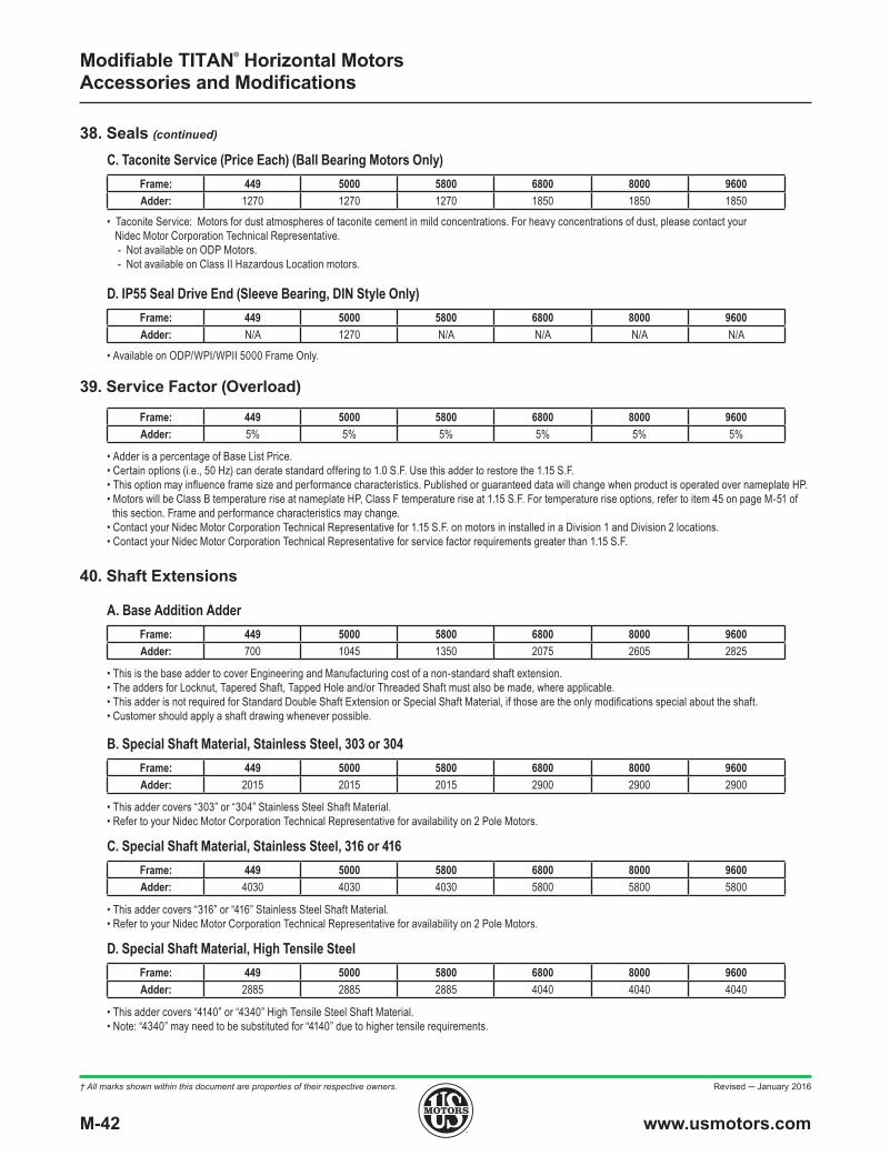
C. Taconite Service (Price Each) (Ball Bearing Motors Only)
D. IP55 Seal Drive End (Sleeve Bearing, DIN Style Only)
• Taconite Service: Motors for dust atmospheres of taconite cement in mild concentrations. For heavy concentrations of dust, please contact your Nidec Motor Corporation Technical Representative. - Not available on ODP Motors. - Not available on Class II Hazardous Location motors.
Frame: 449 5000 5800 6800 8000 9600Adder: 5% 5% 5% 5% 5% 5%
• Adder is a percentage of Base List Price.• Certain options (i.e., 50 Hz) can derate standard offering to 1.0 S.F. Use this adder to restore the 1.15 S.F.• This option may influence frame size and performance characteristics. Published or guaranteed data will change when product is operated over nameplate HP.• Motors will be Class B temperature rise at nameplate HP, Class F temperature rise at 1.15 S.F. For temperature rise options, refer to item 45 on page M-51 of this section. Frame and performance characteristics may change.• Contact your Nidec Motor Corporation Technical Representative for 1.15 S.F. on motors in installed in a Division 1 and Division 2 locations.• Contact your Nidec Motor Corporation Technical Representative for service factor requirements greater than 1.15 S.F.
Frame: 449 5000 5800 6800 8000 9600Adder: 700 1045 1350 2075 2605 2825
Frame: 449 5000 5800 6800 8000 9600Adder: 2015 2015 2015 2900 2900 2900
Frame: 449 5000 5800 6800 8000 9600Adder: 4030 4030 4030 5800 5800 5800
Frame: 449 5000 5800 6800 8000 9600Adder: 2885 2885 2885 4040 4040 4040
A. Base Addition Adder
B. Special Shaft Material, Stainless Steel, 303 or 304
C. Special Shaft Material, Stainless Steel, 316 or 416
D. Special Shaft Material, High Tensile Steel
• This is the base adder to cover Engineering and Manufacturing cost of a non-standard shaft extension.• The adders for Locknut, Tapered Shaft, Tapped Hole and/or Threaded Shaft must also be made, where applicable.• This adder is not required for Standard Double Shaft Extension or Special Shaft Material, if those are the only modifications special about the shaft.• Customer should apply a shaft drawing whenever possible.
• This adder covers “303” or “304” Stainless Steel Shaft Material.• Refer to your Nidec Motor Corporation Technical Representative for availability on 2 Pole Motors.
• Available on ODP/WPI/WPII 5000 Frame Only.
• This adder covers “316” or “416” Stainless Steel Shaft Material.• Refer to your Nidec Motor Corporation Technical Representative for availability on 2 Pole Motors.
• This adder covers “4140” or “4340” High Tensile Steel Shaft Material.• Note: “4340” may need to be substituted for “4140” due to higher tensile requirements.
Revised ─ January 2016

www.usmotors.com M-43
† All marks shown within this document are properties of their respective owners.
40. Shaft Extensions (continued)
41. Space Heaters
Modifiable TITAN® Horizontal Motors Accessories and Modifications
Frame: 449 5000 5800 6800 8000 9600Adder: 925 1155 1155 1385 1735 1735
Frame: 449 5000 5800 6800 8000 9600Adder: 1330 1330 1330 1330 1330 1330
Frame: 449 5000 5800 6800 8000 9600Adder: 235 235 235 235 235 235
Frame: 449 5000 5800 6800 8000 9600Adder: 1735 1735 1735 1735 1735 1735
Frame: 449 5000 5800 6800 8000 9600Adder: 835 855 1040 1180 1250 1455
Frame: 449 5000 5800 6800 8000 9600Adder: 580 695 750 870 985 1100
Frame: 449 5000 5800 6800 8000 9600Adder: 580 695 750 870 985 1100
E. Standard Double End Shaft Extension
A. Standard Silicone Strip Heaters
F. Locknut On End Shaft
G. Special Shaft Runout
H. Tapered Shaft
I. Tapped Hole
J. Threaded Shaft (External Thread)
• Adder includes Standard Double Shaft Extension.• Customer is required to insulate one of the half couplings.• If the Double End Extension is special in anyway, including having a C-Face, the “Special Extensions, Base Adder” must also be made.
Nidec Motor Corporation recommends low-watt, density-type space heaters be used to prevent condensation within the motor during idle periods. Space heaters are silicone rubber “strip-type” wrapped around and bonded to the end turns. Unlike cartridge-type heaters, these provide even heating with 50°C to 100°C temperature rise within the motor and exceptionally long life. Nidec Motor Corporation no longer offers cartridge-type heaters due to concern about life expectancy. Heater leads are brought out to the main conduit box on ratings, 600 volts and below. A single accessory box is included at no charge for motors rated above 600 volts.
• Standard space heaters are single phase, 50 or 60Hz and available in 115V, 230V, 380V & 460V volt ratings. Please specify detail at order entry.• Heaters are included at no charge (when specified at order entry) on all WPII enclosures.• For Div. 1 Hazardous Location or Division 2 applications, double adder above.• For half voltage space heater (rated 240V operated on 120V) on unclassified area motors, double adder above.
• A Locknut can be supplied by Nidec Motor Corporation when an external thread on the shaft extension is requested.
• Standard offering is 0.003 inches measured with rotor turning freely from the opposite end. - Special Runout of 0.0015 inches available with the adder above.
• Customer must supply the length and pitch of the taper shaft at order entry. The pitch can be defined in multiple ways: - Degrees of taper per side, with gauge line location and size (preferred method). - “Rise over Run” - Length, with the starting and ending diameter.
• Customer must specify thread size & depth.
• Customer must specify thread size & depth.
M-44 www.usmotors.com
† All marks shown within this document are properties of their respective owners.
41. Space Heaters (continued)
Modifiable TITAN® Horizontal Motors Accessories and Modifications
FRAMENOMINAL WATTAGE
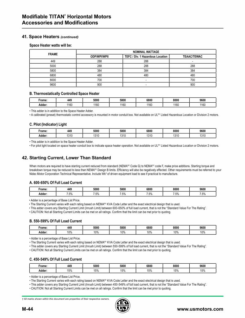
ODP/WPI/WPII TEFC / Div. 1 Hazardous Location TEAAC/TEWAC449 288 288 -5000 288 288 2885800 384 384 3846800 480 480 4808000 700 - 7009600 900 - 900
Space Heater watts will be:
Frame: 449 5000 5800 6800 8000 9600Adder: 1160 1160 1160 1160 1160 1160
Frame: 449 5000 5800 6800 8000 9600Adder: 1310 1310 1310 1310 1310 1310
B. Thermostatically Controlled Space Heater
C. Pilot (Indicator) Light
• This adder is in addition to the Space Heater Adder.• A calibrated (preset) thermostatic control accessory is mounted in motor conduit box. Not available on UL®† Listed Hazardous Location or Division 2 motors.
• This adder is in addition to the Space Heater Adder.• For pilot light located on space heater conduit box to indicate space heater operation. Not available on UL®† Listed Hazardous Location or Division 2 motors.
When motors are required to have starting current reduced from standard (NEMA®† Code G) to NEMA®† code F, make price additions. Starting torque and breakdown torque may be reduced to less than NEMA®† Design B limits. Efficiency will also be negatively effected. Other requirements must be referred to your Nidec Motor Corporation Technical Representative. Include Wk2 of driven equipment load to see if practical to manufacture.
42. Starting Current, Lower Than Standard
Frame: 449 5000 5800 6800 8000 9600Adder: 7.5% 7.5% 7.5% 7.5% 7.5% 7.5%
Frame: 449 5000 5800 6800 8000 9600Adder: 10% 10% 10% 10% 10% 10%
Frame: 449 5000 5800 6800 8000 9600Adder: 15% 15% 15% 15% 15% 15%
A. 600-650% Of Full Load Current
B. 550-599% Of Full Load Current
C. 450-549% Of Full Load Current
• Adder is a percentage of Base List Price.• The Starting Current varies with each rating based on NEMA®† KVA Code Letter and the exact electrical design that is used.• This adder covers any Starting Current Limit (Inrush Limit) between 600-650% of full load current, that is not the “Standard Value For The Rating”.• CAUTION: Not all Starting Current Limits can be met on all ratings. Confirm that the limit can be met prior to quoting.
• Adder is a percentage of Base List Price.• The Starting Current varies with each rating based on NEMA®† KVA Code Letter and the exact electrical design that is used.• This adder covers any Starting Current Limit (Inrush Limit) between 550-599% of full load current, that is not the “Standard Value For The Rating”.• CAUTION: Not all Starting Current Limits can be met on all ratings. Confirm that the limit can be met prior to quoting.
• Adder is a percentage of Base List Price.• The Starting Current varies with each rating based on NEMA®† KVA Code Letter and the exact electrical design that is used.• This adder covers any Starting Current Limit (Inrush Limit) between 450-549% of full load current, that is not the “Standard Value For The Rating”.• CAUTION: Not all Starting Current Limits can be met on all ratings. Confirm that the limit can be met prior to quoting.
www.usmotors.com M-45
† All marks shown within this document are properties of their respective owners.
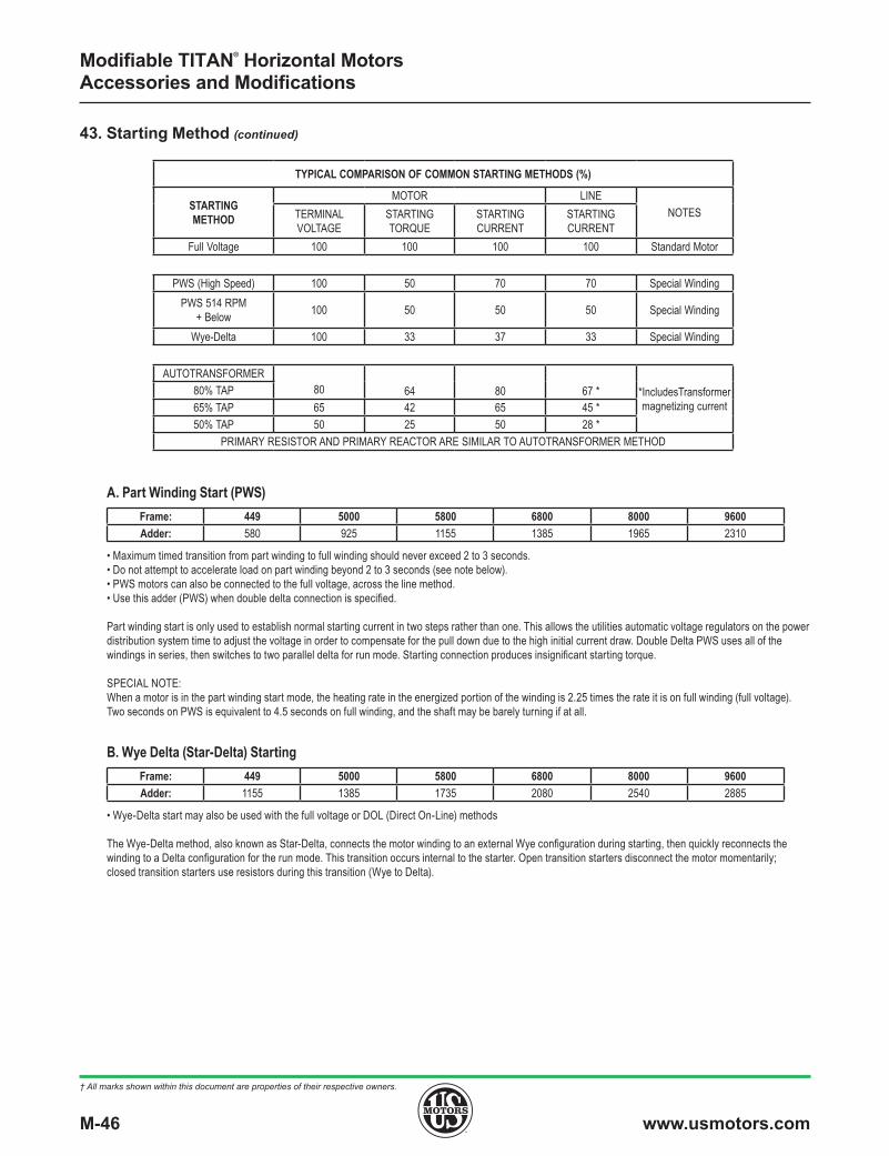
43. Starting Method
Modifiable TITAN® Horizontal Motors Accessories and Modifications
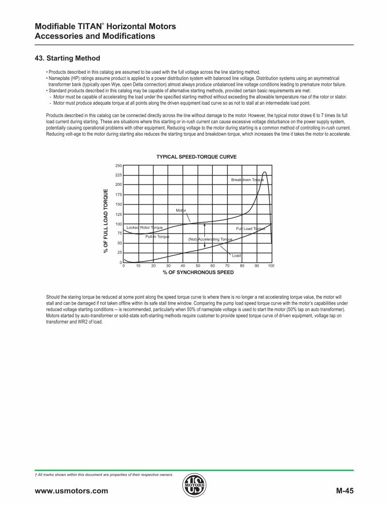
• Products described in this catalog are assumed to be used with the full voltage across the line starting method. • Nameplate (HP) ratings assume product is applied to a power distribution system with balanced line voltage. Distribution systems using an asymmetrical transformer bank (typically open Wye, open Delta connection) almost always produce unbalanced line voltage conditions leading to premature motor failure.• Standard products described in this catalog may be capable of alternative starting methods, provided certain basic requirements are met: - Motor must be capable of accelerating the load under the specified starting method without exceeding the allowable temperature rise of the rotor or stator. - Motor must produce adequate torque at all points along the driven equipment load curve so as not to stall at an intermediate load point.
Products described in this catalog can be connected directly across the line without damage to the motor. However, the typical motor draws 6 to 7 times its full load current during starting. These are situations where this starting or in-rush current can cause excessive voltage disturbance on the power supply system, potentially causing operational problems with other equipment. Reducing voltage to the motor during starting is a common method of controlling in-rush current. Reducing volt-age to the motor during starting also reduces the starting torque and breakdown torque, which increases the time it takes the motor to accelerate.
Should the staring torque be reduced at some point along the speed torque curve to where there is no longer a net accelerating torque value, the motor will stall and can be damaged if not taken offline within its safe stall time window. Comparing the pump load speed torque curve with the motor’s capabilities under reduced voltage starting conditions -- is recommended, particularly when 50% of nameplate voltage is used to start the motor (50% tap on auto transformer). Motors started by auto-transformer or solid-state soft-starting methods require customer to provide speed torque curve of driven equipment, voltage tap on transformer and WR2 of load.
0 10 20 30 40 50 60 70 80 90 1000
25
50
75
100
125
150
175
200
225
250
Motor
Locked Rotor Torque
Pull-in Torque(Not) Accelerating Torque
Load
Full Load Torque
Breakdown Torque
TYPICAL SPEED-TORQUE CURVE
% O
F FU
LL L
OA
D T
OR
QU
E
% OF SYNCHRONOUS SPEED
M-46 www.usmotors.com
† All marks shown within this document are properties of their respective owners.
Modifiable TITAN® Horizontal Motors Accessories and Modifications
Frame: 449 5000 5800 6800 8000 9600Adder: 580 925 1155 1385 1965 2310
Frame: 449 5000 5800 6800 8000 9600Adder: 1155 1385 1735 2080 2540 2885
A. Part Winding Start (PWS)
B. Wye Delta (Star-Delta) Starting
• Maximum timed transition from part winding to full winding should never exceed 2 to 3 seconds. • Do not attempt to accelerate load on part winding beyond 2 to 3 seconds (see note below). • PWS motors can also be connected to the full voltage, across the line method.• Use this adder (PWS) when double delta connection is specified.
Part winding start is only used to establish normal starting current in two steps rather than one. This allows the utilities automatic voltage regulators on the power distribution system time to adjust the voltage in order to compensate for the pull down due to the high initial current draw. Double Delta PWS uses all of the windings in series, then switches to two parallel delta for run mode. Starting connection produces insignificant starting torque.
SPECIAL NOTE: When a motor is in the part winding start mode, the heating rate in the energized portion of the winding is 2.25 times the rate it is on full winding (full voltage). Two seconds on PWS is equivalent to 4.5 seconds on full winding, and the shaft may be barely turning if at all.
• Wye-Delta start may also be used with the full voltage or DOL (Direct On-Line) methods
The Wye-Delta method, also known as Star-Delta, connects the motor winding to an external Wye configuration during starting, then quickly reconnects the winding to a Delta configuration for the run mode. This transition occurs internal to the starter. Open transition starters disconnect the motor momentarily; closed transition starters use resistors during this transition (Wye to Delta).
TYPICAL COMPARISON OF COMMON STARTING METHODS (%)
STARTINGMETHOD
MOTOR LINENOTESTERMINAL
VOLTAGESTARTINGTORQUE
STARTINGCURRENT
STARTINGCURRENT
Full Voltage 100 100 100 100 Standard Motor
PWS (High Speed) 100 50 70 70 Special WindingPWS 514 RPM
+ Below 100 50 50 50 Special Winding
Wye-Delta 100 33 37 33 Special Winding
AUTOTRANSFORMER80 64 80 67 * *IncludesTransformer
magnetizing current80% TAP65% TAP 65 42 65 45 *50% TAP 50 25 50 28 *
PRIMARY RESISTOR AND PRIMARY REACTOR ARE SIMILAR TO AUTOTRANSFORMER METHOD
43. Starting Method (continued)

www.usmotors.com M-47
† All marks shown within this document are properties of their respective owners.
Motor Voltage Surge Capacitors andLightning Arrestors
600V & Below $4,280601-2400V $10,920
2401-4800V $14,1604801-6900V $20,285
44. Surge Protection
45. Temperature Rise, Standard And Optional
• Available as motor mounted. • Do not use this accessory on applications where motor is driven by an inverter. Serious damage to the VFD will result. Consult your drive supplier. • Suitable oversized main conduit box is included in price adders shown.
Surge capacitors and lightning arrestors protect the motor winding from transient voltage spikes and from the incoming distribution system. Distribution system conditions likely to cause turn-to-turn or turn-to-ground winding damage include lightning strikes, capacitor switching, and opening or closing of the system circuit breaker, among others. Should the magnitude of stresses imposed on the winding from system voltage transients exceed the surge limits the motor can withstand, the insulation system will fail.
Lightning arrestors limit the magnitude of the transient voltage spike. This is achieved by the arrestor conducting to ground when the voltage reaches a given value. Surge capacitors limit the rate of rise of the voltage. This is achieved by the capacitor momentarily absorbing the steep wave front.
Surge protection is most effective when it is mounted directly from the main conduit box at the motor leads. Increasing this distance beyond 3 feet significantly reduces its effectiveness. Fusing the capacitors or arrestors is not recommended due to the difficulty in determining if or when the fuse is blown.
• This option may not be available on the maximum HP rating in a given frame size. Consult your Nidec Motor Corporation Technical Representative for availability.• This option may change motor frame size and performance characteristics. Consult your Nidec Motor Corporation Technical Representative for confirmed data. • Combined with other design altering modifications (high ambient, high altitude, VFD use, etc.), this option will significantly change listed product performance described in this catalog. Consult your Nidec Motor Corporation Technical Representative for confirmed frame size, performance data, etc. • The description of this product feature assumes the motor is applied to sine wave power and in accordance with NEMA®† standards (standard ambient, altitude, balanced voltage, etc.).
The standard insulation system supplied on all Nidec Motor Corporation products described in this catalog is Class F. When our Class F system is subjected to insulation life testing as described in IEEE-275TM, it significantly exceeds the thermal capabilities required to classify it as capable of providing 20,000 hours of design life when operated a the Class F thermal limit of 155°C. Chart 44-1 indicates the thermal capabilities of our standard insulation system, which is shown as the diagonal line slightly below Class H.
Modifiable TITAN® Horizontal Motors Accessories and Modifications
Starting Voltage Percent Price Addition69%-65% TAP 12%80%-70% TAP 7.5%
C. Reduced Voltage Starting
If the load inertia is 1/2 of the NEMA®† normal and load torque during acceleration does not exceed 60% of the motor rated torque, no price addition is required down to 75% voltage. Engineering verification of the motor capability is required prior to quotation. If the load inertia is greater than NEMA®†, both the inertia adder and the low voltage adder must be made.
NOTE: Motors designed for low-voltage starting may have higher than the standard in-rush current at full voltage.
Standard motors are capable of accelerating Wk2 loads per the published table as long as the motor terminal voltage does not drop below 80% for NEMA®† or 90% for TITAN® of the nominal motor voltage. For starting at lower than stated guidelines, make the following percentage additions:
43. Starting Method (continued)